EP3702558A1 - Counter lock for an inactive leaf of a double leaf door - Google Patents
Counter lock for an inactive leaf of a double leaf door Download PDFInfo
- Publication number
- EP3702558A1 EP3702558A1 EP19382149.3A EP19382149A EP3702558A1 EP 3702558 A1 EP3702558 A1 EP 3702558A1 EP 19382149 A EP19382149 A EP 19382149A EP 3702558 A1 EP3702558 A1 EP 3702558A1
- Authority
- EP
- European Patent Office
- Prior art keywords
- counter lock
- blocking
- actuating cam
- lock
- neutral position
- Prior art date
- Legal status (The legal status is an assumption and is not a legal conclusion. Google has not performed a legal analysis and makes no representation as to the accuracy of the status listed.)
- Granted
Links
- 230000000903 blocking effect Effects 0.000 claims abstract description 73
- 230000007935 neutral effect Effects 0.000 claims abstract description 32
- 230000008878 coupling Effects 0.000 claims description 20
- 238000010168 coupling process Methods 0.000 claims description 20
- 238000005859 coupling reaction Methods 0.000 claims description 20
- 230000014759 maintenance of location Effects 0.000 claims description 9
- 230000033228 biological regulation Effects 0.000 description 1
- 230000005484 gravity Effects 0.000 description 1
- 238000000034 method Methods 0.000 description 1
- 230000000717 retained effect Effects 0.000 description 1
- 238000012163 sequencing technique Methods 0.000 description 1
Images


Classifications
-
- E—FIXED CONSTRUCTIONS
- E05—LOCKS; KEYS; WINDOW OR DOOR FITTINGS; SAFES
- E05C—BOLTS OR FASTENING DEVICES FOR WINGS, SPECIALLY FOR DOORS OR WINDOWS
- E05C7/00—Fastening devices specially adapted for two wings
- E05C7/04—Fastening devices specially adapted for two wings for wings which abut when closed
-
- E—FIXED CONSTRUCTIONS
- E05—LOCKS; KEYS; WINDOW OR DOOR FITTINGS; SAFES
- E05B—LOCKS; ACCESSORIES THEREFOR; HANDCUFFS
- E05B17/00—Accessories in connection with locks
- E05B17/20—Means independent of the locking mechanism for preventing unauthorised opening, e.g. for securing the bolt in the fastening position
- E05B17/2007—Securing, deadlocking or "dogging" the bolt in the fastening position
- E05B17/203—Securing, deadlocking or "dogging" the bolt in the fastening position not following the movement of the bolt
- E05B17/2034—Securing, deadlocking or "dogging" the bolt in the fastening position not following the movement of the bolt moving pivotally or rotatively
-
- E—FIXED CONSTRUCTIONS
- E05—LOCKS; KEYS; WINDOW OR DOOR FITTINGS; SAFES
- E05B—LOCKS; ACCESSORIES THEREFOR; HANDCUFFS
- E05B63/00—Locks or fastenings with special structural characteristics
- E05B63/24—Arrangements in which the fastening members which engage one another are mounted respectively on the wing and the frame and are both movable, e.g. for release by moving either of them
-
- E—FIXED CONSTRUCTIONS
- E05—LOCKS; KEYS; WINDOW OR DOOR FITTINGS; SAFES
- E05B—LOCKS; ACCESSORIES THEREFOR; HANDCUFFS
- E05B65/00—Locks or fastenings for special use
- E05B65/10—Locks or fastenings for special use for panic or emergency doors
- E05B65/1006—Locks or fastenings for special use for panic or emergency doors of the vertical rod type
-
- E—FIXED CONSTRUCTIONS
- E05—LOCKS; KEYS; WINDOW OR DOOR FITTINGS; SAFES
- E05C—BOLTS OR FASTENING DEVICES FOR WINGS, SPECIALLY FOR DOORS OR WINDOWS
- E05C9/00—Arrangements of simultaneously actuated bolts or other securing devices at well-separated positions on the same wing
- E05C9/04—Arrangements of simultaneously actuated bolts or other securing devices at well-separated positions on the same wing with two sliding bars moved in opposite directions when fastening or unfastening
- E05C9/042—Arrangements of simultaneously actuated bolts or other securing devices at well-separated positions on the same wing with two sliding bars moved in opposite directions when fastening or unfastening with pins engaging slots
-
- E—FIXED CONSTRUCTIONS
- E05—LOCKS; KEYS; WINDOW OR DOOR FITTINGS; SAFES
- E05B—LOCKS; ACCESSORIES THEREFOR; HANDCUFFS
- E05B15/00—Other details of locks; Parts for engagement by bolts of fastening devices
- E05B15/004—Lost motion connections
Definitions
- the present invention relates to a counter lock for an inactive leaf for a double leaf door.
- Emergency doors or fire doors comprising a main leaf in turn comprising a lock and a secondary leaf comprising a counter lock are known.
- the counter lock works together with the lock to block the door.
- These doors are configured to withstand stresses as required by law, where they can only be opened when the user acts on the lock or counter lock. When acting on the lock only the main leaf opens, whereas both leaves open when acting on the counter lock.
- the secondary leaf is blocked at upper and lower blocking points by means of rods that are coupled to the counter lock, particularly to respective sliders housed in the counter lock, and at the ends of which there are arranged bolts which are inserted in respective housings, blocking the secondary leaf.
- the counter lock furthermore includes a central blocking point with the lock such that a latch of the lock is housed in the counter lock when the door is closed.
- EP1524390A2 describes a counter lock comprising sliders which move vertically and have ends coupled to the corresponding rods, a laminar element that can be actuated through a security bar and includes a front which can retain the sliders in the retracted position until the leaf closes completely and a latch of the lock is coupled in the counter lock.
- the selvage includes a pusher which retains the latch of the lock when the door is closed, the pusher including a coupling tooth which engaged a toothed ring rotating with respect to the sliders.
- the object of the invention is to provide a counter lock for an inactive leaf for a double leaf door, as defined in the claims.
- the counter lock comprises an actuating cam coupled to a follower, an upper slider configured for being coupled to an upper rod through which the blocking of the inactive leaf at an upper blocking point is maintained when the counter lock is in a neutral position, a lower slider configured for being coupled to a lower rod through which the blocking of the inactive leaf at a lower blocking point is maintained when the counter lock is in the neutral position, both sliders being movable with respect to one another, the actuating cam being configured for moving at least one of the sliders when the follower is rotated in an opening direction causing the release of the upper and lower blocking points of the inactive leaf, and a pusher configured for actuating a latch of a lock, with the latch being housed at least partially in the counter lock when the counter lock is in the neutral position blocking an active leaf of the double leaf door at a central blocking point.
- the actuating cam is configured for actuating, in a first step, the pusher when the follower is rotated in the opening direction causing the release of the central blocking point, and to then, in a second step, move at least one of the sliders unblocking the upper and lower blocking points of the inactive leaf.
- the counter lock enables the sequential opening of the blocking points of the door.
- the central blocking point is released first, and once said blocking point has been released, the actuating cam acts on one of the sliders causing the release of the upper and lower blocking points. Therefore, the user will have to apply less force to open the door while still complying with the requirements of the existing regulations.
- FIG. 1 shows an emergency door 1 comprising a lock 4.
- the emergency door 1 comprises a main leaf 2 also known as the active leaf comprising the lock 4 and a secondary leaf 3 also known as the inactive leaf comprising a counter lock 5 according to the invention.
- the counter lock 5 When the lock 4 is acted on, only the main leaf 2 opens, whereas when the counter lock 5 is acted on both leaves 2 and 3 open.
- the counter lock 5 When arranged in a blocking position, the counter lock 5 maintains the blocking of the secondary leaf 3 at an upper blocking point A, a lower blocking point B, and a central point C as schematically shown in Figures 1 and 2 .
- Said blocking position is also referred to as the neutral position or the closed-door position.
- the emergency door 1 comprises an upper rod 18 fixed at one end to the counter lock 5 and at the free end of which there is inserted a bolt 13, and a lower rod 19 fixed at one end to the counter lock 5 and at the free end of which there is inserted another bolt 14, such that each bolt 13 and 14 is configured for being housed in a corresponding housing 27 and 28 comprised respectively in the floor and in a frame of a wall in which the emergency door 1 is arranged, with the corresponding bolts 13 and 14 being retained inside the respective housing 27 and 28 defining the lower blocking point B and the upper blocking point A, respectively.
- the blocking at the central point C takes place through a latch 8 of the lock 4 which, in the neutral position, goes through a front 7 of the counter lock 5, being partially housed in the counter lock 5.
- This geometry of the bolts together with the configuration of the counter lock 5 prevents the bolts 13 and 14 from giving way when excessive forces are applied during panic or fire situations, leading to the door 1 becoming overloaded, preventing said door from being able to be open.
- the counter lock 5 shown in the drawings is mainly adapted to emergency doors as shown in Figures 1 and 2 , although it may be used in another type of doors.
- FIGS 3 to 9 and 13 to 14 show an embodiment of the counter lock 5 in which some of the components of said counter lock 5 not relevant for the invention have been eliminated to facilitate understanding thereof.
- the counter lock 5 comprises a lock case 6 housing a follower 10 configured for being operated by a handle (not depicted) or a panic or emergency device 9 depicted in Figures 1 and 2 , an upper slider 12 configured for being coupled to the upper rod 18, a lower slider 15 configured for being coupled to the lower rod 19, and an actuating cam 30 coupled to the follower 10, both sliders 12 and 15 being movable with respect to one another and the actuating cam 30 being configured for moving at least one of the sliders 12 and 15 when it is operated in an opening direction, thereby releasing the upper blocking point A and the lower blocking point B of the secondary leaf 3.
- the counter lock 5 further comprises a pusher 50 which, in the neutral position, is housed in the lock case 6 and partially ejected from the lock case 6, striking the latch 8 of the lock 4 and releasing the central blocking point C when the follower 10 is rotated in the opening direction. Therefore, from the neutral position, the rotation of the actuating cam 30 in the opening direction causes the release of the upper blocking point A and the lower blocking point B of the counter lock 5 and of the central blocking point C of the lock 4 by means of said actuating cam 30 directly actuating one of the sliders 12 and 15 and the pusher 50, respectively.
- the pusher 50 is pivotably coupled to the lock case 6 through the corresponding coupling 51.
- the pusher 50 In the neutral position, the pusher 50 is supported on the actuating cam 30, particularly on a support surface 35 arranged in a projection 34 of the actuating cam 30.
- the support between the pusher 50 and the actuating cam 30 in the neutral position is arranged below the coupling rotating shaft 51, thereby forcing the pusher 50 to remain supported on the actuating cam 30 as a result of gravity.
- the counter lock 5 comprises blocking means 60 configured for maintaining the blocking of the movement of the sliders 12 and 15 in the neutral position of the counter lock 5, the blocking means 60 comprising a swing 20 and a retention surface 36 of the actuating cam 30 which retains the swing 20 in the neutral position preventing the movement of the sliders 12 and 15, the blocking means 60 being unblocked when the follower 10 is rotated in the opening direction.
- the inactive leaf 3 is blocked in the upper blocking point A, lower blocking point B, and central blocking point C. From said neutral position in which the door is blocked, and when pressure is applied on the door, said door can be opened quickly and at any time by rotating the follower 10 in the opening direction.
- the swing 20 comprises a wedge-like projection 23 which, in the neutral position, abuts with the retention surface 36 of the actuating cam 30.
- the retention surface 36 is a curved surface. In the embodiment shown in the drawings, the retention surface 36 is a curved surface substantially concentric to an axis of rotation of the actuating cam 30.
- the swing 20 is pivotably coupled to the lock case 6 of the counter lock 5 through a first coupling 24, said swing 20 furthermore being coupled to the lower slider 15 and the upper slider 12, respectively, through a second coupling 21 and a third coupling 22, said second coupling 21 and third coupling 22 being arranged at opposite ends of the swing 20.
- the first coupling 24 is arranged substantially centered in the swing 20.
- the upper slider 12 and the lower slider 15 move relatively with respect to one another in a substantially vertical manner when they are operated by the actuating cam 30.
- both sliders 12 and 15 move closer to one another, forcing the upper rod 18 and the lower rod 19 to move closer to one another, releasing the corresponding bolts 13 and 14 from the corresponding housings 27 and 28, thereby releasing the upper blocking position A and the lower blocking position B, whereas when the follower 10 returns to its starting position as a result of a spring 55, the sliders 12 and 15 move away from one another as a result of respective return springs 56 and 57, with the upper rod 18 and the lower rod 19 returning to the upper blocking position A and the lower blocking position B.
- the movement of the upper slider 12 and the lower slider 15 is a guided movement, said movement being substantially vertical.
- the actuating cam 30 shown in detail in Figure 11 comprises a hole 33 through which it is concentrically and integrally coupled to the follower 10 and an arm 31 including an actuating surface 32 configured for pushing and moving the lower slider 15 when the follower 10 is rotated in the opening direction.
- the actuating surface 32 acts on a stop 16 arranged at an upper end 15a of the lower slider 15.
- the support surface 35 of the actuating cam 30 is configured for causing the rotation of the pusher 50 in the direction opposite the opening direction of the follower 10 when the follower 10 is operated, causing the partial ejection of said pusher 50 out of the lock case 6 and the corresponding release of the central blocking point C as it strikes the latch 8 of the lock 4, retracting it.
- the actuating cam 30 rotates in the opening direction, rotating the pusher 50 in the direction opposite the direction for opening and releasing the central blocking point C in a first step, before coming into contact with the lower slider 15.
- the actuating cam 30 is rotated in the opening direction from the neutral position (shown in Figures 3 to 5 ) until the actuating surface 32 of said actuating cam 30 contacts the stop 16 arranged at the upper end 15a of the lower slider 15 (shown in Figure 6 ), the retention surface 36 of the actuating cam 30 remains in contact with the end 23b of the projection 23 of the swing 20. During said travel, the swing 20 does not rotate.
- the secondary leaf 3 can be opened by acting directly on the follower 10 of the counter lock 5 or on a pull 40 housed in the lock case 6.
- the pull 40 is pivotably coupled to the lock case 6 through a respective coupling 41.
- the pull 40 comprises a projection 43 going through the front 7 of the counter lock 5, being accessible from outside the secondary leaf 3, and an extension 42 housed inside the lock case 6.
- the pull 40 rotates in the opening direction with respect to the coupling 41, the extension 42 of the pull 40 pushing the actuating cam 30 and causing it to rotate in the opening direction as seen in Figures 13 to 15 .
- the pull 40 directly contacts the actuating cam 30 through the extension 42.
Abstract
Description
- The present invention relates to a counter lock for an inactive leaf for a double leaf door.
- Emergency doors or fire doors comprising a main leaf in turn comprising a lock and a secondary leaf comprising a counter lock are known. The counter lock works together with the lock to block the door. These doors are configured to withstand stresses as required by law, where they can only be opened when the user acts on the lock or counter lock. When acting on the lock only the main leaf opens, whereas both leaves open when acting on the counter lock.
- The secondary leaf is blocked at upper and lower blocking points by means of rods that are coupled to the counter lock, particularly to respective sliders housed in the counter lock, and at the ends of which there are arranged bolts which are inserted in respective housings, blocking the secondary leaf. When the counter lock is actuated, said blocking points are eliminated, making it possible to open the door. The counter lock furthermore includes a central blocking point with the lock such that a latch of the lock is housed in the counter lock when the door is closed.
-
EP1524390A2 describes a counter lock comprising sliders which move vertically and have ends coupled to the corresponding rods, a laminar element that can be actuated through a security bar and includes a front which can retain the sliders in the retracted position until the leaf closes completely and a latch of the lock is coupled in the counter lock. To block the sliders in the position in which the door is open, the selvage includes a pusher which retains the latch of the lock when the door is closed, the pusher including a coupling tooth which engaged a toothed ring rotating with respect to the sliders. - The object of the invention is to provide a counter lock for an inactive leaf for a double leaf door, as defined in the claims.
- The counter lock according to the invention comprises an actuating cam coupled to a follower, an upper slider configured for being coupled to an upper rod through which the blocking of the inactive leaf at an upper blocking point is maintained when the counter lock is in a neutral position, a lower slider configured for being coupled to a lower rod through which the blocking of the inactive leaf at a lower blocking point is maintained when the counter lock is in the neutral position, both sliders being movable with respect to one another, the actuating cam being configured for moving at least one of the sliders when the follower is rotated in an opening direction causing the release of the upper and lower blocking points of the inactive leaf, and a pusher configured for actuating a latch of a lock, with the latch being housed at least partially in the counter lock when the counter lock is in the neutral position blocking an active leaf of the double leaf door at a central blocking point.
- The actuating cam is configured for actuating, in a first step, the pusher when the follower is rotated in the opening direction causing the release of the central blocking point, and to then, in a second step, move at least one of the sliders unblocking the upper and lower blocking points of the inactive leaf.
- The counter lock enables the sequential opening of the blocking points of the door. By acting directly on the follower or on the manual pull, the central blocking point is released first, and once said blocking point has been released, the actuating cam acts on one of the sliders causing the release of the upper and lower blocking points. Therefore, the user will have to apply less force to open the door while still complying with the requirements of the existing regulations.
- These and other advantages and features of the invention will become evident in view of the drawings and detailed description of the invention.
-
-
Figure 1 shows a schematic front view of a double leaf door comprising a counter lock according to the invention. -
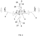
Figure 2 shows an exploded view of the elements comprised in the double leaf door shown inFigure 1 . -
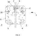
Figure 3 shows in detail the counter lock and a lock of the double leaf door both shown inFigure 1 , arranged in a neutral position. -
Figure 4 shows a front view of the counter lock shown inFigure 1 in the neutral position. -
Figure 5 shows another front view of the counter lock shown inFigure 1 . -
Figure 6 shows a front view of the counter lock shown inFigure 1 in a first position in which the follower is operated. -
Figure 7 shows a front view of the counter lock shown inFigure 1 in a second position in which the follower is operated. -
Figure 8 shows a front view of the counter lock shown inFigure 1 in a position in which the lock is open. -
Figure 9 shows another front view of the counter lock shown inFigure 1 in the position in which the lock is open. -
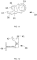
Figure 10 shows a detailed view of the swing comprised in the counter lock shown inFigure 1 . -
Figure 11 shows a detailed view of the actuating cam comprised in the counter lock shown inFigure 1 . -
Figure 12 shows a detailed view of the pull comprised in the counter lock shown inFigure 1 . -
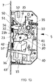
Figure 13 shows a detailed view of the counter lock shown inFigure 1 operated by means of the pull in an initial unblocking position. -
Figure 14 shows a detailed view of the counter lock shown inFigure 1 operated by means of the pull in an intermediate unblocking position. -
Figure 1 shows anemergency door 1 comprising alock 4. Theemergency door 1 comprises amain leaf 2 also known as the active leaf comprising thelock 4 and asecondary leaf 3 also known as the inactive leaf comprising acounter lock 5 according to the invention. - When the
lock 4 is acted on, only themain leaf 2 opens, whereas when thecounter lock 5 is acted on bothleaves counter lock 5 maintains the blocking of thesecondary leaf 3 at an upper blocking point A, a lower blocking point B, and a central point C as schematically shown inFigures 1 and2 . Said blocking position is also referred to as the neutral position or the closed-door position. - The
emergency door 1 comprises anupper rod 18 fixed at one end to thecounter lock 5 and at the free end of which there is inserted abolt 13, and alower rod 19 fixed at one end to thecounter lock 5 and at the free end of which there is inserted anotherbolt 14, such that eachbolt corresponding housing emergency door 1 is arranged, with thecorresponding bolts respective housing latch 8 of thelock 4 which, in the neutral position, goes through afront 7 of thecounter lock 5, being partially housed in thecounter lock 5. This geometry of the bolts together with the configuration of thecounter lock 5 prevents thebolts door 1 becoming overloaded, preventing said door from being able to be open. - The
counter lock 5 shown in the drawings is mainly adapted to emergency doors as shown inFigures 1 and2 , although it may be used in another type of doors. -
Figures 3 to 9 and13 to 14 show an embodiment of thecounter lock 5 in which some of the components of saidcounter lock 5 not relevant for the invention have been eliminated to facilitate understanding thereof. Thecounter lock 5 comprises alock case 6 housing afollower 10 configured for being operated by a handle (not depicted) or a panic oremergency device 9 depicted inFigures 1 and2 , anupper slider 12 configured for being coupled to theupper rod 18, alower slider 15 configured for being coupled to thelower rod 19, and anactuating cam 30 coupled to thefollower 10, bothsliders actuating cam 30 being configured for moving at least one of thesliders secondary leaf 3. - The
counter lock 5 further comprises apusher 50 which, in the neutral position, is housed in thelock case 6 and partially ejected from thelock case 6, striking thelatch 8 of thelock 4 and releasing the central blocking point C when thefollower 10 is rotated in the opening direction. Therefore, from the neutral position, the rotation of the actuatingcam 30 in the opening direction causes the release of the upper blocking point A and the lower blocking point B of thecounter lock 5 and of the central blocking point C of thelock 4 by means of said actuatingcam 30 directly actuating one of thesliders pusher 50, respectively. - The
pusher 50 is pivotably coupled to thelock case 6 through thecorresponding coupling 51. In the neutral position, thepusher 50 is supported on the actuatingcam 30, particularly on asupport surface 35 arranged in aprojection 34 of the actuatingcam 30. In thecounter lock 5, the support between thepusher 50 and the actuatingcam 30 in the neutral position is arranged below thecoupling rotating shaft 51, thereby forcing thepusher 50 to remain supported on the actuatingcam 30 as a result of gravity. - Moreover, the
counter lock 5 comprises blocking means 60 configured for maintaining the blocking of the movement of thesliders counter lock 5, the blocking means 60 comprising aswing 20 and aretention surface 36 of the actuatingcam 30 which retains theswing 20 in the neutral position preventing the movement of thesliders follower 10 is rotated in the opening direction. As described above, in the neutral position, theinactive leaf 3 is blocked in the upper blocking point A, lower blocking point B, and central blocking point C. From said neutral position in which the door is blocked, and when pressure is applied on the door, said door can be opened quickly and at any time by rotating thefollower 10 in the opening direction. - The
swing 20 comprises a wedge-like projection 23 which, in the neutral position, abuts with theretention surface 36 of the actuatingcam 30. Theretention surface 36 is a curved surface. In the embodiment shown in the drawings, theretention surface 36 is a curved surface substantially concentric to an axis of rotation of the actuatingcam 30. - The
swing 20 is pivotably coupled to thelock case 6 of thecounter lock 5 through afirst coupling 24, saidswing 20 furthermore being coupled to thelower slider 15 and theupper slider 12, respectively, through asecond coupling 21 and athird coupling 22, saidsecond coupling 21 andthird coupling 22 being arranged at opposite ends of theswing 20. Thefirst coupling 24 is arranged substantially centered in theswing 20. - Moreover, the
upper slider 12 and thelower slider 15 move relatively with respect to one another in a substantially vertical manner when they are operated by the actuatingcam 30. When thefollower 10 is rotated in the opening direction, bothsliders upper rod 18 and thelower rod 19 to move closer to one another, releasing thecorresponding bolts corresponding housings follower 10 returns to its starting position as a result of aspring 55, thesliders respective return springs upper rod 18 and thelower rod 19 returning to the upper blocking position A and the lower blocking position B. The movement of theupper slider 12 and thelower slider 15 is a guided movement, said movement being substantially vertical. - The actuating
cam 30 shown in detail inFigure 11 comprises ahole 33 through which it is concentrically and integrally coupled to thefollower 10 and anarm 31 including anactuating surface 32 configured for pushing and moving thelower slider 15 when thefollower 10 is rotated in the opening direction. In particular, the actuatingsurface 32 acts on astop 16 arranged at anupper end 15a of thelower slider 15. In addition to blocking the rotation of thepusher 50 in the neutral position, thesupport surface 35 of the actuatingcam 30 is configured for causing the rotation of thepusher 50 in the direction opposite the opening direction of thefollower 10 when thefollower 10 is operated, causing the partial ejection of saidpusher 50 out of thelock case 6 and the corresponding release of the central blocking point C as it strikes thelatch 8 of thelock 4, retracting it. - When the
follower 10 is rotated in the opening direction by means of a handle or a panic oremergency device 9, theactuating cam 30 rotates in the opening direction, rotating thepusher 50 in the direction opposite the direction for opening and releasing the central blocking point C in a first step, before coming into contact with thelower slider 15. When theactuating cam 30 is rotated in the opening direction from the neutral position (shown inFigures 3 to 5 ) until theactuating surface 32 of saidactuating cam 30 contacts thestop 16 arranged at theupper end 15a of the lower slider 15 (shown inFigure 6 ), theretention surface 36 of theactuating cam 30 remains in contact with theend 23b of theprojection 23 of theswing 20. During said travel, theswing 20 does not rotate. From this position (seeFigures 7 to 9 ), when theactuating cam 30 has rotated a specific angle in the opening direction from the neutral position, theactuating cam 30 moves thelower slider 15, theactuating cam 30 no longer contacting theswing 20. When thelower slider 15 is moved vertically, theswing 20 rotates in the opening direction causing the movement of theupper slider 12 due to thecouplings swing 20 with respect to thesliders counter lock 5 which minimizes the force the user must apply on thefollower 10 of thecounter lock 5 to open thedoor 1 is achieved, complying with the safety requirements demanded of locks of this type. - Finally, the
secondary leaf 3 can be opened by acting directly on thefollower 10 of thecounter lock 5 or on apull 40 housed in thelock case 6. Thepull 40 is pivotably coupled to thelock case 6 through arespective coupling 41. Thepull 40 comprises aprojection 43 going through thefront 7 of thecounter lock 5, being accessible from outside thesecondary leaf 3, and anextension 42 housed inside thelock case 6. When thecounter lock 5 is manually operated from the outside through thepull 40 by actuating theprojection 43 outwards, thepull 40 rotates in the opening direction with respect to thecoupling 41, theextension 42 of thepull 40 pushing theactuating cam 30 and causing it to rotate in the opening direction as seen inFigures 13 to 15 . Thepull 40 directly contacts theactuating cam 30 through theextension 42. Once thepull 40 has rotated theactuating cam 30, the unblocking process described for the case in which theactuating cam 30 is rotated through thefollower 10 is repeated upon acting on a handle or safety device, so the entire description above upon rotation of theactuating cam 30 is also applicable herein and it will not be repeated.
Claims (12)
- Counter lock for an inactive leaf of a double leaf door, comprising an actuating cam (30) coupled to a follower (10), an upper slider (12) configured for being coupled to an upper rod (18) through which the blocking of the inactive leaf (3) at an upper blocking point (A) is maintained when the counter lock (5) is in a neutral position, a lower slider (15) configured for being coupled to a lower rod (19) through which the blocking of the inactive leaf (3) at a lower blocking point (B) is maintained when the counter lock (5) is in the neutral position, both sliders (12, 15) being movable with respect to one another, the actuating cam (30) being configured for moving at least one of the sliders (12, 15) when the follower (10) is rotated in an opening direction causing the release of the upper and lower blocking points (A, B) of the inactive leaf (3), and a pusher (50) configured for actuating a latch (8) of a lock (4), with the latch (8) being housed at least partially in the counter lock (5) when the counter lock (5) is in the neutral position, blocking an active leaf (2) of the double leaf door (1) in a central blocking point (C), characterized in that the actuating cam (30) is configured for actuating, in a first step, the pusher (50) when the follower (10) is rotated in the opening direction causing the release of the central blocking point (C), and to then, in a second step, move at least one of the sliders (12, 15) unblocking the upper and lower blocking points (A, B) of the inactive leaf (3).
- Counter lock for an inactive leaf according to the preceding claim, wherein the actuating cam (30) comprises a support surface (35) which, in the neutral position, contacts the pusher (50), blocking the rotation of the pusher (50), said support surface (35) being configured for acting on the pusher (50) rotating it in the direction opposite the opening direction in the first step when the follower (10) is rotated in the opening direction, and an actuating surface (32) configured for contacting the lower slider (15) in the second step when the actuating cam (30) has rotated a specific angle in the opening direction from the neutral position.
- Counter lock for an inactive leaf according to the preceding claim, wherein, in the neutral position, the actuating surface (32) does not contact the lower slider (15).
- Counter lock for an inactive leaf according to claim 2 or 3, wherein the pusher (50) is coupled through a coupling (51), said pusher (50) being pivotable with respect to said coupling (51), the support between the pusher (50) and the actuating cam (30) being arranged in the neutral position below the axis of rotation of the coupling (51), forcing the pusher (50) to remain supported on the actuating cam (30).
- Counter lock for an inactive leaf according to any of the preceding claims, comprising blocking means (60) to maintain the blocking of the movement of the sliders (12, 15) in the neutral position of the counter lock (5), the blocking means (60) comprising a swing (20) coupled to at least one slider (12, 15), the actuating cam (30) in the neutral position blocking the rotation of the swing (20), preventing the sliders (12, 15) from moving, the blocking means (60) being unblocked when the follower (10) is rotated in the opening direction.
- Counter lock for an inactive leaf according to the preceding claim, wherein the swing (20) comprises a wedge-like projection (23) which, in the neutral position, abuts with a retention surface (36) of the actuating cam (30).
- Counter lock for an inactive leaf according to the preceding claim, wherein the retention surface (36) of the actuating cam (30) is a curved surface.
- Counter lock for an inactive leaf according to the preceding claim, wherein the retention surface (36) is a curved surface substantially concentric to an axis of rotation of the actuating cam (30).
- Counter lock for an inactive leaf according to any of claims 6 to 8, wherein an end (23b) of the projection (23) of the swing (20) maintains contact with the retention surface (36) of the actuating cam (30) during rotation of the actuating cam (30) in the opening direction from the neutral position until the actuating surface (32) contacts the lower slider (15), the actuating cam (30) preventing the rotation of the swing (20).
- Counter lock for an inactive leaf according to any of the preceding claims, wherein the swing (20) is pivotably coupled to a lock case (6) of the counter lock (5) through a first coupling (24), said swing (20) furthermore being coupled respectively to the lower slider (15) and the upper slider (12) through a second coupling (21) and a third coupling (22), said second coupling (21) and third coupling (22) being arranged at opposite ends of the swing (20).
- Counter lock for an inactive leaf according to any of the preceding claims, comprising a pull (40) including a projection (43) accessible from outside the counter lock (5), and an extension (42) configured for actuating the actuating cam (30) such that, when the pull (40) is operated through the projection (43), it causes the rotation of the actuating cam (30) and the release of blocking points (A, B) of the inactive leaf (3).
- Counter lock for an inactive leaf according to the preceding claim, wherein the pull (40) directly contacts the actuating cam (30) through the extension (42) when the pull (40) is operated from outside, causing said extension (42) to pivot the actuating cam (30) in the opening direction.
Priority Applications (2)
| Application Number | Priority Date | Filing Date | Title |
|---|---|---|---|
| EP19382149.3A EP3702558B1 (en) | 2019-02-28 | 2019-02-28 | Counter lock for an inactive leaf of a double leaf door |
| ES19382149T ES2906213T3 (en) | 2019-02-28 | 2019-02-28 | Passive leaf counterlock for a double leaf door |
Applications Claiming Priority (1)
| Application Number | Priority Date | Filing Date | Title |
|---|---|---|---|
| EP19382149.3A EP3702558B1 (en) | 2019-02-28 | 2019-02-28 | Counter lock for an inactive leaf of a double leaf door |
Publications (2)
| Publication Number | Publication Date |
|---|---|
| EP3702558A1 true EP3702558A1 (en) | 2020-09-02 |
| EP3702558B1 EP3702558B1 (en) | 2022-01-12 |
Family
ID=65817951
Family Applications (1)
| Application Number | Title | Priority Date | Filing Date |
|---|---|---|---|
| EP19382149.3A Active EP3702558B1 (en) | 2019-02-28 | 2019-02-28 | Counter lock for an inactive leaf of a double leaf door |
Country Status (2)
| Country | Link |
|---|---|
| EP (1) | EP3702558B1 (en) |
| ES (1) | ES2906213T3 (en) |
Citations (3)
| Publication number | Priority date | Publication date | Assignee | Title |
|---|---|---|---|---|
| EP1524390A2 (en) | 2003-10-15 | 2005-04-20 | CISA S.p.A. | Selvage for a secondary wing of fire doors |
| DE202006001383U1 (en) * | 2006-01-27 | 2006-04-13 | Bks Gmbh | Shot-bolt lock |
| EP2264268A2 (en) * | 2009-06-15 | 2010-12-22 | BKS GmbH | Drive bar lock |
-
2019
- 2019-02-28 EP EP19382149.3A patent/EP3702558B1/en active Active
- 2019-02-28 ES ES19382149T patent/ES2906213T3/en active Active
Patent Citations (3)
| Publication number | Priority date | Publication date | Assignee | Title |
|---|---|---|---|---|
| EP1524390A2 (en) | 2003-10-15 | 2005-04-20 | CISA S.p.A. | Selvage for a secondary wing of fire doors |
| DE202006001383U1 (en) * | 2006-01-27 | 2006-04-13 | Bks Gmbh | Shot-bolt lock |
| EP2264268A2 (en) * | 2009-06-15 | 2010-12-22 | BKS GmbH | Drive bar lock |
Also Published As
| Publication number | Publication date |
|---|---|
| EP3702558B1 (en) | 2022-01-12 |
| ES2906213T3 (en) | 2022-04-13 |
Similar Documents
| Publication | Publication Date | Title |
|---|---|---|
| US7677067B2 (en) | Lock | |
| US6174004B1 (en) | Mortise latch and exit device with concealed vertical rods | |
| US8182002B2 (en) | Multipoint door lock system with header and sill lock pins | |
| KR100759713B1 (en) | Automatic close device and system of fire door | |
| AU2012322987A1 (en) | Highly safe control mechanism for a device for the sealed transfer between two closed spaces | |
| EP1521891B1 (en) | Door locking mechanism | |
| KR101887462B1 (en) | Electromagnetic door opener | |
| US1346670A (en) | Panic-bolt mechanism | |
| US9932758B2 (en) | Watertight door or window | |
| US5992100A (en) | Door jamb assembly | |
| DE102011051952A1 (en) | Lock for locking system of door, has coupling device, which remains in closed position, where operative connection between latch actuating unit and latch bolt is realized | |
| US5673948A (en) | Remote lock operation control means | |
| HU223791B1 (en) | Double-wing door, especially a fire protection door | |
| EP3702558A1 (en) | Counter lock for an inactive leaf of a double leaf door | |
| EP3426867B1 (en) | Lock | |
| EP3702557B1 (en) | Counter lock for an inactive leaf of a double door | |
| CN111902593B (en) | Window or door | |
| EP0649958B2 (en) | Lock for the secondary leaf of fire doors | |
| EP1715121A2 (en) | Improvements in and relating to a latch mechanism | |
| EP3911821B1 (en) | Panel closure apparatus | |
| EP2569497B1 (en) | Door having a device for openable latching of the door | |
| CA2299597C (en) | Mortise latch and exit device with concealed vertical rods | |
| CN108222700B (en) | Locking device for a two-leaf door | |
| AU720571B2 (en) | Door jamb assembly | |
| EP1505230A1 (en) | Lock with rotary latch |
Legal Events
| Date | Code | Title | Description |
|---|---|---|---|
| PUAI | Public reference made under article 153(3) epc to a published international application that has entered the european phase |
Free format text: ORIGINAL CODE: 0009012 |
|
| STAA | Information on the status of an ep patent application or granted ep patent |
Free format text: STATUS: THE APPLICATION HAS BEEN PUBLISHED |
|
| AK | Designated contracting states |
Kind code of ref document: A1 Designated state(s): AL AT BE BG CH CY CZ DE DK EE ES FI FR GB GR HR HU IE IS IT LI LT LU LV MC MK MT NL NO PL PT RO RS SE SI SK SM TR |
|
| AX | Request for extension of the european patent |
Extension state: BA ME |
|
| STAA | Information on the status of an ep patent application or granted ep patent |
Free format text: STATUS: REQUEST FOR EXAMINATION WAS MADE |
|
| 17P | Request for examination filed |
Effective date: 20210210 |
|
| RBV | Designated contracting states (corrected) |
Designated state(s): AL AT BE BG CH CY CZ DE DK EE ES FI FR GB GR HR HU IE IS IT LI LT LU LV MC MK MT NL NO PL PT RO RS SE SI SK SM TR |
|
| GRAP | Despatch of communication of intention to grant a patent |
Free format text: ORIGINAL CODE: EPIDOSNIGR1 |
|
| STAA | Information on the status of an ep patent application or granted ep patent |
Free format text: STATUS: GRANT OF PATENT IS INTENDED |
|
| INTG | Intention to grant announced |
Effective date: 20211001 |
|
| GRAS | Grant fee paid |
Free format text: ORIGINAL CODE: EPIDOSNIGR3 |
|
| GRAA | (expected) grant |
Free format text: ORIGINAL CODE: 0009210 |
|
| STAA | Information on the status of an ep patent application or granted ep patent |
Free format text: STATUS: THE PATENT HAS BEEN GRANTED |
|
| AK | Designated contracting states |
Kind code of ref document: B1 Designated state(s): AL AT BE BG CH CY CZ DE DK EE ES FI FR GB GR HR HU IE IS IT LI LT LU LV MC MK MT NL NO PL PT RO RS SE SI SK SM TR |
|
| REG | Reference to a national code |
Ref country code: GB Ref legal event code: FG4D |
|
| REG | Reference to a national code |
Ref country code: CH Ref legal event code: EP |
|
| REG | Reference to a national code |
Ref country code: DE Ref legal event code: R096 Ref document number: 602019010865 Country of ref document: DE |
|
| REG | Reference to a national code |
Ref country code: IE Ref legal event code: FG4D |
|
| REG | Reference to a national code |
Ref country code: AT Ref legal event code: REF Ref document number: 1462495 Country of ref document: AT Kind code of ref document: T Effective date: 20220215 |
|
| REG | Reference to a national code |
Ref country code: ES Ref legal event code: FG2A Ref document number: 2906213 Country of ref document: ES Kind code of ref document: T3 Effective date: 20220413 |
|
| REG | Reference to a national code |
Ref country code: LT Ref legal event code: MG9D |
|
| REG | Reference to a national code |
Ref country code: NL Ref legal event code: MP Effective date: 20220112 |
|
| REG | Reference to a national code |
Ref country code: AT Ref legal event code: MK05 Ref document number: 1462495 Country of ref document: AT Kind code of ref document: T Effective date: 20220112 |
|
| PG25 | Lapsed in a contracting state [announced via postgrant information from national office to epo] |
Ref country code: NL Free format text: LAPSE BECAUSE OF FAILURE TO SUBMIT A TRANSLATION OF THE DESCRIPTION OR TO PAY THE FEE WITHIN THE PRESCRIBED TIME-LIMIT Effective date: 20220112 |
|
| PG25 | Lapsed in a contracting state [announced via postgrant information from national office to epo] |
Ref country code: SE Free format text: LAPSE BECAUSE OF FAILURE TO SUBMIT A TRANSLATION OF THE DESCRIPTION OR TO PAY THE FEE WITHIN THE PRESCRIBED TIME-LIMIT Effective date: 20220112 Ref country code: RS Free format text: LAPSE BECAUSE OF FAILURE TO SUBMIT A TRANSLATION OF THE DESCRIPTION OR TO PAY THE FEE WITHIN THE PRESCRIBED TIME-LIMIT Effective date: 20220112 Ref country code: PT Free format text: LAPSE BECAUSE OF FAILURE TO SUBMIT A TRANSLATION OF THE DESCRIPTION OR TO PAY THE FEE WITHIN THE PRESCRIBED TIME-LIMIT Effective date: 20220512 Ref country code: NO Free format text: LAPSE BECAUSE OF FAILURE TO SUBMIT A TRANSLATION OF THE DESCRIPTION OR TO PAY THE FEE WITHIN THE PRESCRIBED TIME-LIMIT Effective date: 20220412 Ref country code: LT Free format text: LAPSE BECAUSE OF FAILURE TO SUBMIT A TRANSLATION OF THE DESCRIPTION OR TO PAY THE FEE WITHIN THE PRESCRIBED TIME-LIMIT Effective date: 20220112 Ref country code: HR Free format text: LAPSE BECAUSE OF FAILURE TO SUBMIT A TRANSLATION OF THE DESCRIPTION OR TO PAY THE FEE WITHIN THE PRESCRIBED TIME-LIMIT Effective date: 20220112 Ref country code: BG Free format text: LAPSE BECAUSE OF FAILURE TO SUBMIT A TRANSLATION OF THE DESCRIPTION OR TO PAY THE FEE WITHIN THE PRESCRIBED TIME-LIMIT Effective date: 20220412 |
|
| PG25 | Lapsed in a contracting state [announced via postgrant information from national office to epo] |
Ref country code: PL Free format text: LAPSE BECAUSE OF FAILURE TO SUBMIT A TRANSLATION OF THE DESCRIPTION OR TO PAY THE FEE WITHIN THE PRESCRIBED TIME-LIMIT Effective date: 20220112 Ref country code: LV Free format text: LAPSE BECAUSE OF FAILURE TO SUBMIT A TRANSLATION OF THE DESCRIPTION OR TO PAY THE FEE WITHIN THE PRESCRIBED TIME-LIMIT Effective date: 20220112 Ref country code: GR Free format text: LAPSE BECAUSE OF FAILURE TO SUBMIT A TRANSLATION OF THE DESCRIPTION OR TO PAY THE FEE WITHIN THE PRESCRIBED TIME-LIMIT Effective date: 20220413 Ref country code: FI Free format text: LAPSE BECAUSE OF FAILURE TO SUBMIT A TRANSLATION OF THE DESCRIPTION OR TO PAY THE FEE WITHIN THE PRESCRIBED TIME-LIMIT Effective date: 20220112 Ref country code: AT Free format text: LAPSE BECAUSE OF FAILURE TO SUBMIT A TRANSLATION OF THE DESCRIPTION OR TO PAY THE FEE WITHIN THE PRESCRIBED TIME-LIMIT Effective date: 20220112 |
|
| REG | Reference to a national code |
Ref country code: DE Ref legal event code: R119 Ref document number: 602019010865 Country of ref document: DE |
|
| PG25 | Lapsed in a contracting state [announced via postgrant information from national office to epo] |
Ref country code: IS Free format text: LAPSE BECAUSE OF FAILURE TO SUBMIT A TRANSLATION OF THE DESCRIPTION OR TO PAY THE FEE WITHIN THE PRESCRIBED TIME-LIMIT Effective date: 20220512 |
|
| REG | Reference to a national code |
Ref country code: CH Ref legal event code: PL |
|
| REG | Reference to a national code |
Ref country code: BE Ref legal event code: MM Effective date: 20220228 |
|
| PG25 | Lapsed in a contracting state [announced via postgrant information from national office to epo] |
Ref country code: SM Free format text: LAPSE BECAUSE OF FAILURE TO SUBMIT A TRANSLATION OF THE DESCRIPTION OR TO PAY THE FEE WITHIN THE PRESCRIBED TIME-LIMIT Effective date: 20220112 Ref country code: SK Free format text: LAPSE BECAUSE OF FAILURE TO SUBMIT A TRANSLATION OF THE DESCRIPTION OR TO PAY THE FEE WITHIN THE PRESCRIBED TIME-LIMIT Effective date: 20220112 Ref country code: RO Free format text: LAPSE BECAUSE OF FAILURE TO SUBMIT A TRANSLATION OF THE DESCRIPTION OR TO PAY THE FEE WITHIN THE PRESCRIBED TIME-LIMIT Effective date: 20220112 Ref country code: MC Free format text: LAPSE BECAUSE OF FAILURE TO SUBMIT A TRANSLATION OF THE DESCRIPTION OR TO PAY THE FEE WITHIN THE PRESCRIBED TIME-LIMIT Effective date: 20220112 Ref country code: LU Free format text: LAPSE BECAUSE OF NON-PAYMENT OF DUE FEES Effective date: 20220228 Ref country code: EE Free format text: LAPSE BECAUSE OF FAILURE TO SUBMIT A TRANSLATION OF THE DESCRIPTION OR TO PAY THE FEE WITHIN THE PRESCRIBED TIME-LIMIT Effective date: 20220112 Ref country code: DK Free format text: LAPSE BECAUSE OF FAILURE TO SUBMIT A TRANSLATION OF THE DESCRIPTION OR TO PAY THE FEE WITHIN THE PRESCRIBED TIME-LIMIT Effective date: 20220112 Ref country code: CZ Free format text: LAPSE BECAUSE OF FAILURE TO SUBMIT A TRANSLATION OF THE DESCRIPTION OR TO PAY THE FEE WITHIN THE PRESCRIBED TIME-LIMIT Effective date: 20220112 |
|
| PLBE | No opposition filed within time limit |
Free format text: ORIGINAL CODE: 0009261 |
|
| STAA | Information on the status of an ep patent application or granted ep patent |
Free format text: STATUS: NO OPPOSITION FILED WITHIN TIME LIMIT |
|
| PG25 | Lapsed in a contracting state [announced via postgrant information from national office to epo] |
Ref country code: AL Free format text: LAPSE BECAUSE OF FAILURE TO SUBMIT A TRANSLATION OF THE DESCRIPTION OR TO PAY THE FEE WITHIN THE PRESCRIBED TIME-LIMIT Effective date: 20220112 |
|
| 26N | No opposition filed |
Effective date: 20221013 |
|
| PG25 | Lapsed in a contracting state [announced via postgrant information from national office to epo] |
Ref country code: LI Free format text: LAPSE BECAUSE OF NON-PAYMENT OF DUE FEES Effective date: 20220228 Ref country code: IE Free format text: LAPSE BECAUSE OF NON-PAYMENT OF DUE FEES Effective date: 20220228 Ref country code: FR Free format text: LAPSE BECAUSE OF NON-PAYMENT OF DUE FEES Effective date: 20220312 Ref country code: DE Free format text: LAPSE BECAUSE OF NON-PAYMENT OF DUE FEES Effective date: 20220901 Ref country code: CH Free format text: LAPSE BECAUSE OF NON-PAYMENT OF DUE FEES Effective date: 20220228 |
|
| PG25 | Lapsed in a contracting state [announced via postgrant information from national office to epo] |
Ref country code: SI Free format text: LAPSE BECAUSE OF FAILURE TO SUBMIT A TRANSLATION OF THE DESCRIPTION OR TO PAY THE FEE WITHIN THE PRESCRIBED TIME-LIMIT Effective date: 20220112 Ref country code: BE Free format text: LAPSE BECAUSE OF NON-PAYMENT OF DUE FEES Effective date: 20220228 |
|
| PGFP | Annual fee paid to national office [announced via postgrant information from national office to epo] |
Ref country code: ES Payment date: 20230314 Year of fee payment: 5 |
|
| PG25 | Lapsed in a contracting state [announced via postgrant information from national office to epo] |
Ref country code: IT Free format text: LAPSE BECAUSE OF FAILURE TO SUBMIT A TRANSLATION OF THE DESCRIPTION OR TO PAY THE FEE WITHIN THE PRESCRIBED TIME-LIMIT Effective date: 20220112 |
|
| GBPC | Gb: european patent ceased through non-payment of renewal fee |
Effective date: 20230228 |
|
| PG25 | Lapsed in a contracting state [announced via postgrant information from national office to epo] |
Ref country code: GB Free format text: LAPSE BECAUSE OF NON-PAYMENT OF DUE FEES Effective date: 20230228 |
|
| PG25 | Lapsed in a contracting state [announced via postgrant information from national office to epo] |
Ref country code: GB Free format text: LAPSE BECAUSE OF NON-PAYMENT OF DUE FEES Effective date: 20230228 |
|
| PGFP | Annual fee paid to national office [announced via postgrant information from national office to epo] |
Ref country code: ES Payment date: 20240306 Year of fee payment: 6 |