EP3702308A1 - Elevator cabin - Google Patents
Elevator cabin Download PDFInfo
- Publication number
- EP3702308A1 EP3702308A1 EP19160328.1A EP19160328A EP3702308A1 EP 3702308 A1 EP3702308 A1 EP 3702308A1 EP 19160328 A EP19160328 A EP 19160328A EP 3702308 A1 EP3702308 A1 EP 3702308A1
- Authority
- EP
- European Patent Office
- Prior art keywords
- elevator car
- elevator
- opening
- hoistway
- extending
- Prior art date
- Legal status (The legal status is an assumption and is not a legal conclusion. Google has not performed a legal analysis and makes no representation as to the accuracy of the status listed.)
- Granted
Links
Images


Classifications
-
- B—PERFORMING OPERATIONS; TRANSPORTING
- B66—HOISTING; LIFTING; HAULING
- B66B—ELEVATORS; ESCALATORS OR MOVING WALKWAYS
- B66B5/00—Applications of checking, fault-correcting, or safety devices in elevators
- B66B5/0043—Devices enhancing safety during maintenance
- B66B5/005—Safety of maintenance personnel
- B66B5/0056—Safety of maintenance personnel by preventing crushing
- B66B5/0062—Safety of maintenance personnel by preventing crushing by devices, being operable or not, mounted on the elevator car
-
- B—PERFORMING OPERATIONS; TRANSPORTING
- B66—HOISTING; LIFTING; HAULING
- B66B—ELEVATORS; ESCALATORS OR MOVING WALKWAYS
- B66B11/00—Main component parts of lifts in, or associated with, buildings or other structures
- B66B11/02—Cages, i.e. cars
- B66B11/0226—Constructional features, e.g. walls assembly, decorative panels, comfort equipment, thermal or sound insulation
- B66B11/0246—Maintenance features
-
- B—PERFORMING OPERATIONS; TRANSPORTING
- B66—HOISTING; LIFTING; HAULING
- B66B—ELEVATORS; ESCALATORS OR MOVING WALKWAYS
- B66B5/00—Applications of checking, fault-correcting, or safety devices in elevators
- B66B5/02—Applications of checking, fault-correcting, or safety devices in elevators responsive to abnormal operating conditions
-
- B—PERFORMING OPERATIONS; TRANSPORTING
- B66—HOISTING; LIFTING; HAULING
- B66B—ELEVATORS; ESCALATORS OR MOVING WALKWAYS
- B66B1/00—Control systems of elevators in general
- B66B1/34—Details, e.g. call counting devices, data transmission from car to control system, devices giving information to the control system
- B66B1/3415—Control system configuration and the data transmission or communication within the control system
- B66B1/3423—Control system configuration, i.e. lay-out
-
- B—PERFORMING OPERATIONS; TRANSPORTING
- B66—HOISTING; LIFTING; HAULING
- B66B—ELEVATORS; ESCALATORS OR MOVING WALKWAYS
- B66B1/00—Control systems of elevators in general
- B66B1/34—Details, e.g. call counting devices, data transmission from car to control system, devices giving information to the control system
- B66B1/46—Adaptations of switches or switchgear
- B66B1/50—Adaptations of switches or switchgear with operating or control mechanisms mounted in the car or cage or in the lift well or hoistway
-
- B—PERFORMING OPERATIONS; TRANSPORTING
- B66—HOISTING; LIFTING; HAULING
- B66B—ELEVATORS; ESCALATORS OR MOVING WALKWAYS
- B66B11/00—Main component parts of lifts in, or associated with, buildings or other structures
- B66B11/02—Cages, i.e. cars
- B66B11/0226—Constructional features, e.g. walls assembly, decorative panels, comfort equipment, thermal or sound insulation
-
- B—PERFORMING OPERATIONS; TRANSPORTING
- B66—HOISTING; LIFTING; HAULING
- B66B—ELEVATORS; ESCALATORS OR MOVING WALKWAYS
- B66B3/00—Applications of devices for indicating or signalling operating conditions of elevators
- B66B3/002—Indicators
-
- B—PERFORMING OPERATIONS; TRANSPORTING
- B66—HOISTING; LIFTING; HAULING
- B66B—ELEVATORS; ESCALATORS OR MOVING WALKWAYS
- B66B5/00—Applications of checking, fault-correcting, or safety devices in elevators
- B66B5/0006—Monitoring devices or performance analysers
- B66B5/0012—Devices monitoring the users of the elevator system
-
- B—PERFORMING OPERATIONS; TRANSPORTING
- B66—HOISTING; LIFTING; HAULING
- B66B—ELEVATORS; ESCALATORS OR MOVING WALKWAYS
- B66B5/00—Applications of checking, fault-correcting, or safety devices in elevators
- B66B5/0006—Monitoring devices or performance analysers
- B66B5/0018—Devices monitoring the operating condition of the elevator system
-
- B—PERFORMING OPERATIONS; TRANSPORTING
- B66—HOISTING; LIFTING; HAULING
- B66B—ELEVATORS; ESCALATORS OR MOVING WALKWAYS
- B66B5/00—Applications of checking, fault-correcting, or safety devices in elevators
- B66B5/0043—Devices enhancing safety during maintenance
- B66B5/005—Safety of maintenance personnel
-
- B—PERFORMING OPERATIONS; TRANSPORTING
- B66—HOISTING; LIFTING; HAULING
- B66B—ELEVATORS; ESCALATORS OR MOVING WALKWAYS
- B66B5/00—Applications of checking, fault-correcting, or safety devices in elevators
- B66B5/02—Applications of checking, fault-correcting, or safety devices in elevators responsive to abnormal operating conditions
- B66B5/021—Applications of checking, fault-correcting, or safety devices in elevators responsive to abnormal operating conditions the abnormal operating conditions being independent of the system
- B66B5/025—Applications of checking, fault-correcting, or safety devices in elevators responsive to abnormal operating conditions the abnormal operating conditions being independent of the system where the abnormal operating condition is caused by human behaviour or misbehaviour, e.g. forcing the doors
Definitions
- the invention relates to a method of controlling movement of an elevator car within a hoistway of an elevator system.
- the invention further relates to an elevator system comprising an elevator drive which is configured for employing such a method.
- An elevator system comprises an elevator car moving along a hoistway extending between a plurality of landings, and an elevator drive configured for driving the elevator car.
- the elevator system may comprise components arranged within the hoistway outside the elevator car, which need to be accessed for maintenance and/or repair.
- the elevator car may comprise at least one opening allowing a mechanic to access such components by reaching out of the elevator car.
- an elevator car defining an interior space comprises at least one opening providing a passage between the interior space and an exterior of the elevator car allowing a person within the interior space to reach out of the interior space, and at least one sensor configured for detecting any object extending through the at least one opening.
- the at least one sensor may be connected with an alarm device device issuing an acoustical/audible and/or optical/visible alarm when an object extending through the at least one opening is detected.
- the at least one sensor may issue a signal to an elevator drive, in particular to a controller, of the elevator system for preventing any movement of the elevator car when an object extending through the at least one opening is detected.
- the object detected by the sensor in particular may be a part of human body, such as a head, an arm and/or a foot, of a mechanic reaching out of the elevator car.
- Exemplary embodiments of the invention further include an elevator system comprising a hoistway extending between a plurality of landings; at least one elevator car according to an exemplary embodiment of the invention, which is configured for moving along the hoistway between the plurality of landings; and an elevator drive configured for moving the elevator car along the hoistway.
- the at least one sensor of the elevator car may be connected with the elevator drive and configured for preventing any movement of the elevator car when an object extending through the at least one opening is detected.
- Exemplary embodiments of the invention further include a method of moving an elevator car in such an elevator system.
- the method includes providing input to the elevator drive via an input device; moving the elevator car according to said input; and stopping and preventing any movement of the elevator car when the sensor detects an object, in particular a part of a human body, extending through the at least one opening.
- Exemplary embodiments of the invention also include a method of moving an elevator car in such an elevator system, wherein the method includes providing input to the elevator drive via an input device; moving the elevator car according to said input; determining the current position of the elevator car; and stopping and preventing any movement of the elevator, when the sensor detects an object, in particular a part of a human body, extending through the at least one opening, and the determined position of the elevator car is within a predetermined distance from an end of the hoistway and/or the elevator car is moving towards said end of the hoistway reducing the distance between the elevator car and said end of the hoistway.
- Exemplary embodiments of the invention further include a method of maintaining and/or repairing an elevator system according to an exemplary embodiment of the invention, wherein the method includes employing the method according to an exemplary embodiment of the invention for moving the at least one elevator car to a predetermined position within the hoistway, stopping the at least one elevator car at said predetermined position, and accessing a component of the elevator system outside the at least one elevator car by reaching through the at least one opening of the elevator car.
- Exemplary embodiments of the invention allow for safe operation, maintenance and repair of an elevator system, in particular including accessing components of the elevator system within the hoistway, even when a person, in particular a mechanic, is reaching out of the elevator car into the hoistway.
- Exemplary embodiments of the invention allow reducing the clearance between the elevator car and components arranged within the hoistway requested by the safety code (EN81-20).
- the mechanic will be obliged to stay inside the interior space of the elevator car when the elevator car is moving. This avoids all risk of the mechanic being sheared or crushed between the elevator car and components arranged within the hoistway.
- the at least one sensor may include at least one light emitter and at least one light detector, in particular a laser and a laser detector, constituting a light barrier for detecting an object extending through the opening by interrupting the light barrier.
- the at least one sensor may include an ultrasound emitter and a corresponding ultrasound receiver, or a radar wave emitter and a corresponding radar wave receiver for detecting an object extending through the opening due to ultrasound or radar waves reflected by said object.
- the at least one sensor may include an optical camera for detecting an object extending through the opening in at least one picture taken by the camera.
- the elevator car may comprise a platform allowing a person standing on the platform to reach trough the at least one opening.
- the platform may be movable between a storage position, in which it does not interfere with passengers within the elevator car, and a working position, in which it provides access to the at least one opening.
- an opening may be formed within the top (ceiling), bottom (floor) and/or within at least one sidewall of the elevator car.
- an elevator system may comprise an input device provided within or at the elevator car, the input device being configured for receiving and transmitting manual inputs to the elevator drive for controlling the movement of the elevator car.
- Figure 1 schematically depicts an elevator system 2.
- the elevator system 2 includes an elevator car 60 movably arranged within a hoistway 4 extending between a plurality of landings 10.
- the elevator car 60 in particular is movable in a longitudinal (vertical) direction along a plurality of car guide members 14, such as guide rails, extending along the vertical direction of the hoistway 4. Only one of said car guide members 14 is depicted in Figure 1 .
- elevator car 60 Although only one elevator car 60 is shown in Figure 1 , the skilled person understands that exemplary embodiments of the invention may include elevator systems 2 including a plurality of elevator cars 60 moving in one or more hoistways 4.
- the elevator car 60 comprises a top (ceiling) 62, a bottom (floor) 64 and a plurality of sidewalls 65 extending between the top 62 and the bottom 64 of the elevator car 60 defining an interior space 61 of the elevator car 60.
- the elevator car 60 is movably suspended by means of a tension member 3.
- the tension member 3 for example a rope or belt, is connected to an elevator drive 5, which is configured for driving the tension member 3 in order to move the elevator car 60 along the height of the hoistway 4 between the plurality of landings 10, which are located on different floors.
- the exemplary embodiment shown in Figure 1 uses a 1:1 roping for suspending the elevator car 60.
- the skilled person easily understands that the type of the roping is not essential for the invention and that different kinds of roping, e.g. a 2:1 roping or a 4:1 roping may be used as well.
- the tension member 3 may be a rope, e.g. a steel wire rope, or a belt.
- the tension member 3 may be uncoated or may have a coating, e.g. in the form of a polymer jacket.
- the tension member 3 may be a belt comprising a plurality of polymer coated steel cords (not shown).
- the elevator system 2 may have a traction drive including a traction sheave for driving the tension member 3.
- the elevator system 2 may be an elevator system 2 without a tension member 3.
- the elevator system 2 also may comprise e.g. a hydraulic drive or a linear drive.
- the elevator system 2 may have a machine room (not shown) or it may be a machine room-less elevator system 2.
- the elevator system 2 further includes a counterweight 19 attached to the tension member 3 and configured for moving concurrently and in opposite direction with respect to the elevator car 60 along at least one counterweight guide member 15.
- a counterweight 19 attached to the tension member 3 and configured for moving concurrently and in opposite direction with respect to the elevator car 60 along at least one counterweight guide member 15.
- Each landing 10 is provided with a landing door 11, and the elevator car 60 is provided with a corresponding elevator car door 12 for allowing passengers to transfer between a landing 10 and the interior of the elevator car 60 when the elevator car 60 is positioned at the respective landing 10.
- the elevator drive 5 includes an elevator controller 6 which is configured for controlling the elevator drive 5 for moving the elevator car 60 along the hoistway 4 between the different landings 10.
- Input to the elevator drive 5, in particular to the controller 6, may be provided via landing control panels 7a, which are provided on each landing 10 close to the landing doors 11, and/or via an elevator car control panel 7b, which is provided inside the elevator car 60.
- the landing control panels 7a and the elevator car control panel 7b may be connected with the elevator drive 5 by means of electric wires, which are not shown in Figure 1 , in particular by an electric bus, or by means of wireless data connections.
- the elevator car 60 may be equipped with at least one position reference system 20, which is configured for detecting and/or determining the position of the elevator car 60 within the hoistway 4.
- the position reference system 20 may be an absolute position reference system 20, including a position detector 22 configured for interacting with a coded tape 24 extending along the length of the hoistway 4.
- the position reference system 20 may comprise a position detector 22 which is configured for determining the current position of the elevator car 60 within the hoistway 4 by detecting and integrating velocities and/or accelerations of the elevator car 60.
- Figures 2 to 5 depict perspective views of an elevator car 60 according to an exemplary embodiment of the invention during maintenance and/or repair procedures.
- a mechanic 70 within the interior space 61 of the elevator car has opened an opening 66 provided at the top 62 of the elevator car 60 allowing him to reach through the top 62 of the elevator car 60 for accessing the component 76.
- the mechanic 70 may use at least one tool 73 when working on said component 76.
- the opening 66 extends basically completely over the top 62 of the elevator car 60.
- the opening 66 may extend only over a portion of the top 62 of the elevator car 60 and/or the elevator car 60 may comprise two or more openings 66 provided at different positions at the top 62 of the elevator car 60.
- Similar openings may be formed within the bottom 64 and/or within at least one sidewall 65 of the elevator car 60, respectively.
- the elevator car 60 may comprise a movable platform 68, which is movable between a storage position (not shown), e.g. at the top 62 or at the bottom 64 of the interior space 61, and a working position, in which it is depicted in Figures 2 to 5 .
- a mechanic 70 may step onto the platform 68 for reaching through an opening 66 in the upper part of the elevator car 60.
- the platform 68 may be mounted to the elevator car 60 by at least one scissor mechanism 69 extending between the platform 68 and the top 62 of the elevator car 60, as it is exemplarily depicted in Figures 2 to 5 .
- a ladder 72 may be provided for allowing the mechanic 70 to climb conveniently onto the platform 68 when it is arranged in the working position in some distance above the bottom 64 of the elevator car 60.
- the elevator car 2 is equipped with at least one sensor 82 (see Figures 4 and 5 ), which is configured for monitoring an opening 66 of the elevator car 60 and for detecting any object 75, in particular any tools 73 used by the mechanic 70 or parts 71 of a human body, extending through said opening 66.
- a plurality of sensors 82 are provided next to each other establishing a virtual safety curtain 80 extending across the opening 66.
- sensors 82 are provided with reference signs in Figures 4 and 5 .
- the at least one sensor 82 is connected with the elevator drive 5, in particular the controller 6.
- the elevator drive 5 is configured for stopping and/or preventing any movement of the elevator car 60 when the at least one sensor 82 detects any object 75, in particular a tool 73 or a part 71 of a human body, extending through the opening 66.
- the at least one sensor 82 may be connected with the elevator drive 5 by means of electrical wires (not shown), including a bus system, such as a CAN bus, or by a wireless data connection.
- electrical wires including a bus system, such as a CAN bus, or by a wireless data connection.
- the at least one sensor 82 may be implemented creating a light barrier, in particular a light barrier including at least one laser light source, extending over the whole opening 66.
- the sensor 82 may constitute a plurality of light barriers, wherein each of the light barriers monitors a section of the opening 66.
- the at least one sensor 82 may employ ultrasonic or radar waves for detecting any objects 75 extending though the opening 66, or it may comprise least one optical camera, which is configured for monitoring the opening 66 and detecting any objects 75 extending though the opening 66. Combination of different techniques are possible as well.
- the elevator car 60 is allowed to move only when all tools 73 and parts 71 of a human body, in particular of a mechanic 70 being present within the elevator car 60, are completely located within the interior space 61 of the elevator car 60 (see Figures 4 and 5 ), and in particular when no object 75 extends though the opening 66 of the elevator car 60.
- An input device 74 in particular a manual service control device, may be provided within the elevator car 60.
- the input device 74 may be configured for allowing the mechanic 70 being present on the platform 68 to manually control the movement of the elevator car 60, in particular for moving the elevator car 60 to a position within the hoistway 4 which allows convenient access to a desired component 76 of the elevator system 2.
- the input device 74 may be positioned and configured so that the mechanic 70 is able to move the elevator car 60 by operating the input device 74 only when his body is completely within the interior space 61 of the elevator car 60.
- Such a safety measure might be circumvented by two mechanics 70 cooperating with each other, in particular by a first mechanic 70 reaching out of the opening 66 and a second mechanic 70 operating the input device 74.
- the elevator car 60 may be equipped with an alarm device 78 which is configured for issuing an acoustic and/or optical alarm signal in case an object 75 extending through the opening 66 is detected.
- the elevator drive 5 may be configured to allow movement of the elevator car 60 under certain circumstances despite an object 75 extending through the opening is detected.
- the elevator drive 5 may allow the elevator car 60 to move downwards, as in case of a downward motion of the elevator car 60, there is no risk that an object 75 is squeezed between the top 62 of the elevator car 60 and the upper end 41 of the hoistway 4.
- the elevator car 60 even may be allowed to move upwards even if an object 75 extending through an opening 66 formed at the top 62 of the elevator car 60 is detected, as long as a distance D 1 (see Figure 1 ) between the top 62 of the elevator car 60 and the upper end 41 of the hoistway 4 is larger than a predetermined distance providing a sufficiently large safety space between the top 62 of the elevator car 60 and the upper end 41 of the hoistway 4.
- the elevator car 60 may be allowed to move upwards, in case an object 75 is detected as extending though an opening 66 formed within the bottom 64 of the elevator car 60.
- the elevator car 60 even may be allowed to move downwards even if an object 75 extending through an opening 66 formed within the bottom 64 of the elevator car 60 is detected, as long as a distance D2 (see Figure 1 ) between the bottom 64 of the elevator car 60 and the lower end 42 of the hoistway 4 is larger than a predetermined distance providing a sufficiently large safety space between the bottom 64 of the elevator car 60 and the lower end 42 of the hoistway 4.
- the maximum allowable speed of the elevator car 60 may be reduced when the elevator car 60 is allowed to move despite an object 75 extending out of the elevator car 60 into the hoistway 4 is detected.
Landscapes
- Engineering & Computer Science (AREA)
- Automation & Control Theory (AREA)
- Computer Networks & Wireless Communication (AREA)
- Civil Engineering (AREA)
- Mechanical Engineering (AREA)
- Structural Engineering (AREA)
- Maintenance And Inspection Apparatuses For Elevators (AREA)
- Indicating And Signalling Devices For Elevators (AREA)
Abstract
Description
- The invention relates to a method of controlling movement of an elevator car within a hoistway of an elevator system. The invention further relates to an elevator system comprising an elevator drive which is configured for employing such a method.
- An elevator system comprises an elevator car moving along a hoistway extending between a plurality of landings, and an elevator drive configured for driving the elevator car.
- The elevator system may comprise components arranged within the hoistway outside the elevator car, which need to be accessed for maintenance and/or repair. The elevator car may comprise at least one opening allowing a mechanic to access such components by reaching out of the elevator car. When the elevator car moves or starts to move while a mechanic is reaching out of the elevator car, there is a risk that parts of the human body of the mechanic are squeezed between the elevator car and the hoistway.
- It therefore is desirable to prevent the elevator car from moving while a person is reaching out of an elevator car.
- According to an exemplary embodiment of the invention, an elevator car defining an interior space comprises at least one opening providing a passage between the interior space and an exterior of the elevator car allowing a person within the interior space to reach out of the interior space, and at least one sensor configured for detecting any object extending through the at least one opening.
- The at least one sensor may be connected with an alarm device device issuing an acoustical/audible and/or optical/visible alarm when an object extending through the at least one opening is detected. Alternatively or additionally, the at least one sensor may issue a signal to an elevator drive, in particular to a controller, of the elevator system for preventing any movement of the elevator car when an object extending through the at least one opening is detected.
- The object detected by the sensor in particular may be a part of human body, such as a head, an arm and/or a foot, of a mechanic reaching out of the elevator car.
- Exemplary embodiments of the invention further include an elevator system comprising a hoistway extending between a plurality of landings; at least one elevator car according to an exemplary embodiment of the invention, which is configured for moving along the hoistway between the plurality of landings; and an elevator drive configured for moving the elevator car along the hoistway. In such an elevator system, the at least one sensor of the elevator car may be connected with the elevator drive and configured for preventing any movement of the elevator car when an object extending through the at least one opening is detected.
- Exemplary embodiments of the invention further include a method of moving an elevator car in such an elevator system. The method includes providing input to the elevator drive via an input device; moving the elevator car according to said input; and stopping and preventing any movement of the elevator car when the sensor detects an object, in particular a part of a human body, extending through the at least one opening.
- Exemplary embodiments of the invention also include a method of moving an elevator car in such an elevator system, wherein the method includes providing input to the elevator drive via an input device; moving the elevator car according to said input; determining the current position of the elevator car; and stopping and preventing any movement of the elevator, when the sensor detects an object, in particular a part of a human body, extending through the at least one opening, and the determined position of the elevator car is within a predetermined distance from an end of the hoistway and/or the elevator car is moving towards said end of the hoistway reducing the distance between the elevator car and said end of the hoistway.
- Exemplary embodiments of the invention further include a method of maintaining and/or repairing an elevator system according to an exemplary embodiment of the invention, wherein the method includes employing the method according to an exemplary embodiment of the invention for moving the at least one elevator car to a predetermined position within the hoistway, stopping the at least one elevator car at said predetermined position, and accessing a component of the elevator system outside the at least one elevator car by reaching through the at least one opening of the elevator car.
- Exemplary embodiments of the invention allow for safe operation, maintenance and repair of an elevator system, in particular including accessing components of the elevator system within the hoistway, even when a person, in particular a mechanic, is reaching out of the elevator car into the hoistway.
- Exemplary embodiments of the invention allow reducing the clearance between the elevator car and components arranged within the hoistway requested by the safety code (EN81-20). According to exemplary embodiments of the invention, the mechanic will be obliged to stay inside the interior space of the elevator car when the elevator car is moving. This avoids all risk of the mechanic being sheared or crushed between the elevator car and components arranged within the hoistway.
- A number of optional features are set out in the following. These features may be realized in particular embodiments, alone or in combination with any of the other features, unless specified otherwise.
- The at least one sensor may include at least one light emitter and at least one light detector, in particular a laser and a laser detector, constituting a light barrier for detecting an object extending through the opening by interrupting the light barrier.
- The at least one sensor may include an ultrasound emitter and a corresponding ultrasound receiver, or a radar wave emitter and a corresponding radar wave receiver for detecting an object extending through the opening due to ultrasound or radar waves reflected by said object.
- The at least one sensor may include an optical camera for detecting an object extending through the opening in at least one picture taken by the camera.
- For providing safe and convenient access through the at least one opening, the elevator car may comprise a platform allowing a person standing on the platform to reach trough the at least one opening. The platform may be movable between a storage position, in which it does not interfere with passengers within the elevator car, and a working position, in which it provides access to the at least one opening. Depending on the position of the components, which are to be accessed, within the hoistway, an opening may be formed within the top (ceiling), bottom (floor) and/or within at least one sidewall of the elevator car.
- In order to allow a mechanic to move the elevator car to a desired position within the hoistway, an elevator system according to an exemplary embodiment of the invention may comprise an input device provided within or at the elevator car, the input device being configured for receiving and transmitting manual inputs to the elevator drive for controlling the movement of the elevator car.
- In the following, an exemplary embodiment of the invention is described in more detail with reference to the enclosed figures.
-
Figure 1 schematically depicts an elevator system comprising an elevator car configured for moving along a hoistway. -
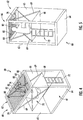
Figures 2 and 3 depict perspective views of an elevator car with a platform arranged in a working position. -
Figures 4 and 5 depict perspective views of an elevator car comprising a platform arranged in a working position and a sensor according to an exemplary embodiment of the invention. -
Figure 1 schematically depicts anelevator system 2. - The
elevator system 2 includes anelevator car 60 movably arranged within ahoistway 4 extending between a plurality oflandings 10. Theelevator car 60 in particular is movable in a longitudinal (vertical) direction along a plurality ofcar guide members 14, such as guide rails, extending along the vertical direction of thehoistway 4. Only one of saidcar guide members 14 is depicted inFigure 1 . - Although only one
elevator car 60 is shown inFigure 1 , the skilled person understands that exemplary embodiments of the invention may includeelevator systems 2 including a plurality ofelevator cars 60 moving in one ormore hoistways 4. - The
elevator car 60 comprises a top (ceiling) 62, a bottom (floor) 64 and a plurality ofsidewalls 65 extending between thetop 62 and thebottom 64 of theelevator car 60 defining aninterior space 61 of theelevator car 60. - The
elevator car 60 is movably suspended by means of atension member 3. Thetension member 3, for example a rope or belt, is connected to anelevator drive 5, which is configured for driving thetension member 3 in order to move theelevator car 60 along the height of thehoistway 4 between the plurality oflandings 10, which are located on different floors. - The exemplary embodiment shown in
Figure 1 uses a 1:1 roping for suspending theelevator car 60. The skilled person, however, easily understands that the type of the roping is not essential for the invention and that different kinds of roping, e.g. a 2:1 roping or a 4:1 roping may be used as well. - The
tension member 3 may be a rope, e.g. a steel wire rope, or a belt. Thetension member 3 may be uncoated or may have a coating, e.g. in the form of a polymer jacket. In a particular embodiment, thetension member 3 may be a belt comprising a plurality of polymer coated steel cords (not shown). Theelevator system 2 may have a traction drive including a traction sheave for driving thetension member 3. In an alternative configuration, which is not shown in the figures, theelevator system 2 may be anelevator system 2 without atension member 3. - The
elevator system 2 also may comprise e.g. a hydraulic drive or a linear drive. Theelevator system 2 may have a machine room (not shown) or it may be a machineroom-less elevator system 2. - The
elevator system 2 further includes acounterweight 19 attached to thetension member 3 and configured for moving concurrently and in opposite direction with respect to theelevator car 60 along at least onecounterweight guide member 15. The skilled person will understand that the invention may be applied also toelevator systems 2 which do not comprise acounterweight 19. - Each
landing 10 is provided with alanding door 11, and theelevator car 60 is provided with a correspondingelevator car door 12 for allowing passengers to transfer between alanding 10 and the interior of theelevator car 60 when theelevator car 60 is positioned at therespective landing 10. - The
elevator drive 5 includes anelevator controller 6 which is configured for controlling theelevator drive 5 for moving theelevator car 60 along thehoistway 4 between thedifferent landings 10. - Input to the
elevator drive 5, in particular to thecontroller 6, may be provided vialanding control panels 7a, which are provided on eachlanding 10 close to thelanding doors 11, and/or via an elevatorcar control panel 7b, which is provided inside theelevator car 60. - The
landing control panels 7a and the elevatorcar control panel 7b may be connected with theelevator drive 5 by means of electric wires, which are not shown inFigure 1 , in particular by an electric bus, or by means of wireless data connections. - The
elevator car 60 may be equipped with at least oneposition reference system 20, which is configured for detecting and/or determining the position of theelevator car 60 within thehoistway 4. - The
position reference system 20 may be an absoluteposition reference system 20, including aposition detector 22 configured for interacting with a codedtape 24 extending along the length of thehoistway 4. Alternatively or additionally, theposition reference system 20 may comprise aposition detector 22 which is configured for determining the current position of theelevator car 60 within thehoistway 4 by detecting and integrating velocities and/or accelerations of theelevator car 60. -
Figures 2 to 5 depict perspective views of anelevator car 60 according to an exemplary embodiment of the invention during maintenance and/or repair procedures. - For accessing a
component 76 of theelevator system 2 located within thehoistway 4 outside theelevator car 60, a mechanic 70 within theinterior space 61 of the elevator car has opened anopening 66 provided at thetop 62 of theelevator car 60 allowing him to reach through thetop 62 of theelevator car 60 for accessing thecomponent 76. Themechanic 70 may use at least one tool 73 when working on saidcomponent 76. - In the exemplary embodiment depicted in
Figures 2 to 5 , the opening 66 extends basically completely over thetop 62 of theelevator car 60. In alternative embodiments, which are not explicitly depicted in the figures, theopening 66 may extend only over a portion of thetop 62 of theelevator car 60 and/or theelevator car 60 may comprise two ormore openings 66 provided at different positions at thetop 62 of theelevator car 60. - Similar openings (not shown) may be formed within the bottom 64 and/or within at least one
sidewall 65 of theelevator car 60, respectively. - The
elevator car 60 may comprise amovable platform 68, which is movable between a storage position (not shown), e.g. at the top 62 or at the bottom 64 of theinterior space 61, and a working position, in which it is depicted inFigures 2 to 5 . When theplatform 68 is arranged in the working position, amechanic 70 may step onto theplatform 68 for reaching through anopening 66 in the upper part of theelevator car 60. - The
platform 68 may be mounted to theelevator car 60 by at least onescissor mechanism 69 extending between theplatform 68 and the top 62 of theelevator car 60, as it is exemplarily depicted inFigures 2 to 5 . Aladder 72 may be provided for allowing the mechanic 70 to climb conveniently onto theplatform 68 when it is arranged in the working position in some distance above the bottom 64 of theelevator car 60. - When the
mechanic 70 is reaching through theopening 66, at least some parts of his body are located within thehoistway 4 outside theinterior space 61 of theelevator car 60. - Thus, in case the
elevator car 60 moves while themechanic 70 is reaching through theopening 66, there is some risk that parts 71 of the mechanic's body are squeezed between theelevator car 60 and the top, walls or bottom of thehoistway 4. - It therefore is desirable to prevent any movement of the
elevator car 60 while themechanic 70 is reaching through anopening 66 of theelevator car 60 into thehoistway 4. - According to an exemplary embodiment of the invention, the
elevator car 2 is equipped with at least one sensor 82 (seeFigures 4 and 5 ), which is configured for monitoring anopening 66 of theelevator car 60 and for detecting any object 75, in particular any tools 73 used by the mechanic 70 or parts 71 of a human body, extending through saidopening 66. - In the embodiment depicted in
Figures 4 and 5 a plurality ofsensors 82 are provided next to each other establishing avirtual safety curtain 80 extending across theopening 66. For clarity of the illustration, not allsensors 82 are provided with reference signs inFigures 4 and 5 . - The at least one
sensor 82 is connected with theelevator drive 5, in particular thecontroller 6. Theelevator drive 5 is configured for stopping and/or preventing any movement of theelevator car 60 when the at least onesensor 82 detects any object 75, in particular a tool 73 or a part 71 of a human body, extending through theopening 66. - The at least one
sensor 82 may be connected with theelevator drive 5 by means of electrical wires (not shown), including a bus system, such as a CAN bus, or by a wireless data connection. - The at least one
sensor 82 may be implemented creating a light barrier, in particular a light barrier including at least one laser light source, extending over thewhole opening 66. Alternatively, thesensor 82 may constitute a plurality of light barriers, wherein each of the light barriers monitors a section of theopening 66. - Instead of creating a light barrier, the at least one
sensor 82 may employ ultrasonic or radar waves for detecting any objects 75 extending though theopening 66, or it may comprise least one optical camera, which is configured for monitoring theopening 66 and detecting any objects 75 extending though theopening 66. Combination of different techniques are possible as well. - In an
elevator system 2 according to an exemplary embodiment of the invention, theelevator car 60 is allowed to move only when all tools 73 and parts 71 of a human body, in particular of a mechanic 70 being present within theelevator car 60, are completely located within theinterior space 61 of the elevator car 60 (seeFigures 4 and 5 ), and in particular when no object 75 extends though theopening 66 of theelevator car 60. - An
input device 74, in particular a manual service control device, may be provided within theelevator car 60. Theinput device 74 may be configured for allowing the mechanic 70 being present on theplatform 68 to manually control the movement of theelevator car 60, in particular for moving theelevator car 60 to a position within thehoistway 4 which allows convenient access to a desiredcomponent 76 of theelevator system 2. - As an additional safety measure, the
input device 74 may be positioned and configured so that themechanic 70 is able to move theelevator car 60 by operating theinput device 74 only when his body is completely within theinterior space 61 of theelevator car 60. - Such a safety measure, however, might be circumvented by two
mechanics 70 cooperating with each other, in particular by afirst mechanic 70 reaching out of theopening 66 and asecond mechanic 70 operating theinput device 74. - In an
elevator system 2 according to an exemplary embodiment of the invention, even such a cooperation of at least twomechanics 70 does not result in an unsafe situation, as any movement of theelevator car 60 is prevented when an object 75, in particular a tool 73 or a part 71 of a human body extends though theopening 66, as it has been described before. - Instead of, or in addition to, stopping and preventing any movement of the
elevator car 60 when an object 75 extending through theopening 66 is detected, theelevator car 60 may be equipped with analarm device 78 which is configured for issuing an acoustic and/or optical alarm signal in case an object 75 extending through theopening 66 is detected. - In a further configuration, the
elevator drive 5 may be configured to allow movement of theelevator car 60 under certain circumstances despite an object 75 extending through the opening is detected. - For example, in case an object 75 extending through an
opening 66 formed at the top 62 of theelevator car 60 is detected, theelevator drive 5 may allow theelevator car 60 to move downwards, as in case of a downward motion of theelevator car 60, there is no risk that an object 75 is squeezed between the top 62 of theelevator car 60 and theupper end 41 of thehoistway 4. - The
elevator car 60 even may be allowed to move upwards even if an object 75 extending through anopening 66 formed at the top 62 of theelevator car 60 is detected, as long as a distance D1 (seeFigure 1 ) between the top 62 of theelevator car 60 and theupper end 41 of thehoistway 4 is larger than a predetermined distance providing a sufficiently large safety space between the top 62 of theelevator car 60 and theupper end 41 of thehoistway 4. - Similarly, the
elevator car 60 may be allowed to move upwards, in case an object 75 is detected as extending though anopening 66 formed within the bottom 64 of theelevator car 60. - The
elevator car 60 even may be allowed to move downwards even if an object 75 extending through anopening 66 formed within the bottom 64 of theelevator car 60 is detected, as long as a distance D2 (seeFigure 1 ) between the bottom 64 of theelevator car 60 and thelower end 42 of thehoistway 4 is larger than a predetermined distance providing a sufficiently large safety space between the bottom 64 of theelevator car 60 and thelower end 42 of thehoistway 4. - Optionally, the maximum allowable speed of the
elevator car 60 may be reduced when theelevator car 60 is allowed to move despite an object 75 extending out of theelevator car 60 into thehoistway 4 is detected. - While the invention has been described with reference to exemplary embodiments, it will be understood by those skilled in the art that various changes may be made and equivalents may be substituted for elements thereof without departing from the scope of the invention. In addition, many modifications may be made to adopt a particular situation or material to the teachings of the invention without departing from the essential scope thereof. Therefore, it is intended that the invention shall not be limited to the particular embodiment disclosed, but that the invention includes all embodiments falling within the scope of the dependent claims.
-
- 2
- elevator system
- 3
- tension member
- 4
- hoistway
- 5
- elevator drive
- 6
- elevator controller
- 7a
- landing control panel
- 7b
- elevator car control panel
- 10
- landing
- 11
- landing door
- 12
- elevator car door
- 14
- car guide member
- 15
- counterweight guide member
- 19
- counterweight
- 20
- position reference system
- 22
- position detector
- 24
- coded tape
- 41
- upper end of the hoistway
- 42
- lower end of the hoistway
- 60
- elevator car
- 61
- interior space
- 62
- top of the elevator car
- 64
- bottom of the elevator car
- 65
- sidewall
- 66
- opening
- 68
- platform
- 69
- scissor mechanism
- 70
- mechanic
- 71
- part of a human body
- 72
- ladder
- 73
- tool
- 74
- input device
- 75
- object
- 76
- component of the elevator system
- 78
- alarm device
- 80
- safety curtain
- 82
- sensor
- D1
- distance between the top of the elevator car and the upper end of the hoistway
- D2
- distance between the bottom of the elevator car and the lower end of the hoistway
Claims (15)
- Elevator car (60) defining an interior space (61) comprising:at least one opening (66) providing a passage between the interior space (61) and the exterior of the elevator car (60); andat least one sensor (82) configured for detecting any object (75) extending through the at least one opening (66).
- Elevator car (60) according to claim 1, wherein the object (75) is a part (71) of a human body or a tool (73) used by a mechanic (70).
- Elevator car (60) according to claim 1 or 2, wherein the at least one sensor (82) is configured for establishing a virtual safety curtain (80) extending across the at least one opening (66).
- Elevator car (60) according to any of the preceding claims, wherein the at least one sensor (82) includes at least one of a light emitter, in particular a laser emitter, a light detector, in particular a laser detector, an ultrasound emitter, an ultrasound receiver, a radar wave emitter, a radar wave receiver and an optical camera, or any combination thereof.
- Elevator car (60) according to any of the preceding claims, further comprising a platform (68) allowing a mechanic (70) standing on the platform (68) to reach through the at least one opening (66).
- Elevator car (60) according to any of the preceding claims, wherein the at least one opening (66) is formed at or in a top (62) of the elevator car (60).
- Elevator car (60) according to any of the preceding claims, wherein the at least one opening (66) is formed in a bottom (64) of the elevator car (60).
- Elevator car (60) according to any of the preceding claims, wherein the at least one opening (66) is formed in a sidewall (65) of the elevator car (60).
- Elevator car (60) according to any of the preceding claims, wherein the at least one sensor (82) is configured for issuing an alarm signal when detecting an object (75) extending through the at least one opening (66).
- Elevator system (2) comprising
a hoistway (4) extending between a plurality of landings (10);
at least one elevator car (60) according to any of the preceding claims configured for moving along the hoistway (4) between the plurality of landings (10); and
an elevator drive (5) configured for moving the elevator car (60) along the hoistway (4). - Elevator system (2) according to claim 10 further wherein the elevator drive (5) is configured for preventing any movement of the elevator car (60) when the sensor (82) detects an object (75) extending through the at least one opening (66).
- Elevator system (2) according to claim 11 comprising an input device (74) provided within or at the elevator car (60), the input device (74) being configured for receiving and transmitting manual inputs to the elevator drive (5) for controlling the movement of the elevator car (60).
- Method of moving an elevator car (60) in an elevator system (2) according to claim 12, wherein the method includes:providing input to the elevator drive (5) via the input device (74);moving the elevator car (60) according to said input; andstopping and preventing any movement of the elevator car (60) when the sensor (82) detects an object (75), in particular a part (71) of a human body or a tool (73), extending through the at least one opening (66).
- Method of moving an elevator car (60) in an elevator system (2) according to claim 12, wherein the method includes:providing input to the elevator drive (5) via the input device (74);moving the elevator car (60) according to said input;determining the current position of the elevator car (60); andstopping and preventing any movement of the elevator car (60), when the sensor (82) detects an object (75), in particular a part (71) of a human body or a tool (73), extending through the at least one opening (66) and the determined position of the elevator car (60) is within a predetermined distance from an end of the hoistway (4) and/or the elevator car (60) is moving towards said end (41, 42) of the hoistway (4) reducing the distance between the elevator car (60) and the end (41, 42) of the hoistway (4) even further.
- Method of maintaining and/or repairing an elevator system (2) according to claim 11, wherein the method includes employing the method according to claim 13 or 14 for moving the at least one elevator car (60) to a predetermined position within the hoistway (4), stopping the at least one elevator car (60) at said predetermined position, and accessing a component (76) of the elevator system (2) outside the at least one elevator car (60) by reaching through the at least one opening (66).
Priority Applications (3)
| Application Number | Priority Date | Filing Date | Title |
|---|---|---|---|
| EP19160328.1A EP3702308B1 (en) | 2019-03-01 | 2019-03-01 | Elevator cabin |
| US16/721,400 US20200277163A1 (en) | 2019-03-01 | 2019-12-19 | Controlling movement of an elevator car |
| CN201911410378.8A CN111634780A (en) | 2019-03-01 | 2019-12-31 | Control the movement of the elevator car |
Applications Claiming Priority (1)
| Application Number | Priority Date | Filing Date | Title |
|---|---|---|---|
| EP19160328.1A EP3702308B1 (en) | 2019-03-01 | 2019-03-01 | Elevator cabin |
Publications (2)
| Publication Number | Publication Date |
|---|---|
| EP3702308A1 true EP3702308A1 (en) | 2020-09-02 |
| EP3702308B1 EP3702308B1 (en) | 2025-07-23 |
Family
ID=65685152
Family Applications (1)
| Application Number | Title | Priority Date | Filing Date |
|---|---|---|---|
| EP19160328.1A Active EP3702308B1 (en) | 2019-03-01 | 2019-03-01 | Elevator cabin |
Country Status (3)
| Country | Link |
|---|---|
| US (1) | US20200277163A1 (en) |
| EP (1) | EP3702308B1 (en) |
| CN (1) | CN111634780A (en) |
Cited By (2)
| Publication number | Priority date | Publication date | Assignee | Title |
|---|---|---|---|---|
| US20200277163A1 (en) * | 2019-03-01 | 2020-09-03 | Otis Elevator Company | Controlling movement of an elevator car |
| US20250353704A1 (en) * | 2024-05-16 | 2025-11-20 | Otis Elevator Company | Method of providing access to at least one component of an elevator system and elevator system |
Families Citing this family (9)
| Publication number | Priority date | Publication date | Assignee | Title |
|---|---|---|---|---|
| EP3760564B1 (en) * | 2019-07-05 | 2023-05-17 | Otis Elevator Company | Elevator car with working platform stabilisation |
| EP3782947B1 (en) * | 2019-08-21 | 2023-02-22 | KONE Corporation | Elevator car shiftable between single and double-decker states |
| ES2941919T3 (en) * | 2019-11-26 | 2023-05-26 | Otis Elevator Co | Elevator cabin with mechanical assistance for work platform |
| US11427441B2 (en) | 2020-07-23 | 2022-08-30 | Otis Elevator Company | Elevator car with foldable working platform |
| ES3058369T3 (en) * | 2022-07-04 | 2026-03-10 | Otis Elevator Co | Elevator cabin with folding work platform |
| EP4332040B1 (en) * | 2022-08-29 | 2025-02-19 | OTIS Elevator Company | An elevator safety device and a method of performing an elevator maintenance and inspection |
| ES3035760T3 (en) * | 2022-09-30 | 2025-09-08 | Otis Elevator Co | Elevator safety system |
| EP4506291A1 (en) * | 2023-08-10 | 2025-02-12 | Otis Elevator Company | Elevator car with stowable working platform |
| US20260084926A1 (en) * | 2024-09-25 | 2026-03-26 | Otis Elevator Company | Exception tool for virtual safety net system |
Citations (4)
| Publication number | Priority date | Publication date | Assignee | Title |
|---|---|---|---|---|
| US20030015378A1 (en) * | 1999-12-27 | 2003-01-23 | Hans Elsener | Inspection opening in an elevator car |
| DE102006023920A1 (en) * | 2006-05-19 | 2007-11-22 | TÜV Rheinland Industrie Service GmbH | Elevator car for elevator system, comprises front surface arranged in surface area, where car is confined to outer edge in shaft direction, and protective chamber is formed between surface area and outer edge |
| US20140231182A1 (en) * | 2011-11-07 | 2014-08-21 | Kone Corporation | Pivoting arrangement, roof element and elevator |
| US20150314991A1 (en) * | 2012-10-30 | 2015-11-05 | Inventio Ag | Elevator with maintenance opening in the car floor |
Family Cites Families (18)
| Publication number | Priority date | Publication date | Assignee | Title |
|---|---|---|---|---|
| JP4397559B2 (en) * | 2000-02-09 | 2010-01-13 | 三菱電機株式会社 | Work safety device on elevator car |
| FR2811971B1 (en) * | 2000-07-21 | 2002-12-13 | Sodimas | ELEVATOR INSTALLATION WITH A REDUCED HEIGHT UPPER LEVEL |
| WO2006067542A1 (en) * | 2004-12-21 | 2006-06-29 | Otis Elevator Company | Elevator safety systems |
| FI121423B (en) * | 2009-04-23 | 2010-11-15 | Kone Corp | Safety arrangement for a lift |
| CN201896017U (en) * | 2010-12-01 | 2011-07-13 | 汪信良 | Car top inspection box |
| WO2016006056A1 (en) * | 2014-07-09 | 2016-01-14 | 三菱電機株式会社 | Elevator system |
| EP3365260B1 (en) * | 2015-10-22 | 2020-09-23 | Kone Corporation | Elevator with a safety arrangement and method for creating a safe working space in the upper part of the elevator shaft |
| WO2018011458A1 (en) * | 2016-07-15 | 2018-01-18 | Kone Corporation | Elevator arrangement to open the roof of an elevator car |
| EP3484804A1 (en) * | 2016-07-15 | 2019-05-22 | KONE Corporation | Elevator arrangement |
| CN109476456B (en) * | 2016-07-15 | 2022-09-09 | 通力股份公司 | Elevator device and elevator |
| CN109476461A (en) * | 2016-07-15 | 2019-03-15 | 通力股份公司 | Elevator installation with low headroom |
| EP3484807B1 (en) * | 2016-07-15 | 2020-07-15 | Kone Corporation | Elevator arrangement for safe maintenance work |
| EP3281904B1 (en) * | 2016-08-09 | 2020-03-25 | Otis Elevator Company | Control systems and methods for elevators |
| US20180170710A1 (en) * | 2016-12-21 | 2018-06-21 | Otis Elevator Company | Elevator hover mode operation using sensor-based potential load change detection |
| CN106966247B (en) * | 2017-02-23 | 2019-03-26 | 上海富士电梯有限公司 | Elevator with human testing defencive function |
| WO2020008099A1 (en) * | 2018-07-02 | 2020-01-09 | Kone Corporation | Elevator car with an openable roof |
| EP3686146B1 (en) * | 2019-01-25 | 2022-05-11 | Otis Elevator Company | Controlling movement of an elevator car |
| EP3702308B1 (en) * | 2019-03-01 | 2025-07-23 | Otis Elevator Company | Elevator cabin |
-
2019
- 2019-03-01 EP EP19160328.1A patent/EP3702308B1/en active Active
- 2019-12-19 US US16/721,400 patent/US20200277163A1/en not_active Abandoned
- 2019-12-31 CN CN201911410378.8A patent/CN111634780A/en active Pending
Patent Citations (4)
| Publication number | Priority date | Publication date | Assignee | Title |
|---|---|---|---|---|
| US20030015378A1 (en) * | 1999-12-27 | 2003-01-23 | Hans Elsener | Inspection opening in an elevator car |
| DE102006023920A1 (en) * | 2006-05-19 | 2007-11-22 | TÜV Rheinland Industrie Service GmbH | Elevator car for elevator system, comprises front surface arranged in surface area, where car is confined to outer edge in shaft direction, and protective chamber is formed between surface area and outer edge |
| US20140231182A1 (en) * | 2011-11-07 | 2014-08-21 | Kone Corporation | Pivoting arrangement, roof element and elevator |
| US20150314991A1 (en) * | 2012-10-30 | 2015-11-05 | Inventio Ag | Elevator with maintenance opening in the car floor |
Cited By (2)
| Publication number | Priority date | Publication date | Assignee | Title |
|---|---|---|---|---|
| US20200277163A1 (en) * | 2019-03-01 | 2020-09-03 | Otis Elevator Company | Controlling movement of an elevator car |
| US20250353704A1 (en) * | 2024-05-16 | 2025-11-20 | Otis Elevator Company | Method of providing access to at least one component of an elevator system and elevator system |
Also Published As
| Publication number | Publication date |
|---|---|
| CN111634780A (en) | 2020-09-08 |
| US20200277163A1 (en) | 2020-09-03 |
| EP3702308B1 (en) | 2025-07-23 |
Similar Documents
| Publication | Publication Date | Title |
|---|---|---|
| EP3702308B1 (en) | Elevator cabin | |
| EP3686146B1 (en) | Controlling movement of an elevator car | |
| US11505427B2 (en) | Elevator with a safety arrangement and method for creating a safe working space in the upper part of the elevator shaft | |
| EP3587323A1 (en) | Elevator system | |
| CN101628676B (en) | Safety device for maintenance of elevator | |
| US11286132B2 (en) | Enhancing the transport capacity of an elevator system | |
| EP3798172B1 (en) | Controlling movement of an elevator car of an elevator system | |
| US20190389695A1 (en) | Elevator system | |
| EP3366626A1 (en) | Elevator safety system and method of monitoring an elevator system | |
| EP3511278A1 (en) | Elevator system and method of positioning an elevator car with high accuracy | |
| EP3434634B2 (en) | Elevator safety device | |
| US20180237260A1 (en) | Elevator safety system and method of monitoring an elevator system | |
| EP3628620B1 (en) | Elevator system | |
| CN110775790A (en) | Elevator door control for passenger exit in a multi-door elevator | |
| EP3560870B1 (en) | Automatic cognitive analysis of elevators to reduce passenger wait time | |
| EP1195346B1 (en) | Elevator device | |
| EP4400466B1 (en) | Emergency stop system for elevator | |
| EP4650312A1 (en) | Method of providing access to at least one component of an elevator system and elevator system | |
| EP0841279A1 (en) | Deceleration time for an elevator car | |
| EP4477602A1 (en) | Elevator system including pit safety interface | |
| JP2610346B2 (en) | Elevator side rescue operation device | |
| JP2015151266A (en) | Elevator escape device and elevator device | |
| CN122071347A (en) | Full-top lowering platform for maintenance from inside the car. | |
| JPH02182685A (en) | Safety device for construction elevator |
Legal Events
| Date | Code | Title | Description |
|---|---|---|---|
| PUAI | Public reference made under article 153(3) epc to a published international application that has entered the european phase |
Free format text: ORIGINAL CODE: 0009012 |
|
| STAA | Information on the status of an ep patent application or granted ep patent |
Free format text: STATUS: THE APPLICATION HAS BEEN PUBLISHED |
|
| AK | Designated contracting states |
Kind code of ref document: A1 Designated state(s): AL AT BE BG CH CY CZ DE DK EE ES FI FR GB GR HR HU IE IS IT LI LT LU LV MC MK MT NL NO PL PT RO RS SE SI SK SM TR |
|
| AX | Request for extension of the european patent |
Extension state: BA ME |
|
| STAA | Information on the status of an ep patent application or granted ep patent |
Free format text: STATUS: REQUEST FOR EXAMINATION WAS MADE |
|
| 17P | Request for examination filed |
Effective date: 20210219 |
|
| RBV | Designated contracting states (corrected) |
Designated state(s): AL AT BE BG CH CY CZ DE DK EE ES FI FR GB GR HR HU IE IS IT LI LT LU LV MC MK MT NL NO PL PT RO RS SE SI SK SM TR |
|
| STAA | Information on the status of an ep patent application or granted ep patent |
Free format text: STATUS: EXAMINATION IS IN PROGRESS |
|
| 17Q | First examination report despatched |
Effective date: 20221130 |
|
| GRAP | Despatch of communication of intention to grant a patent |
Free format text: ORIGINAL CODE: EPIDOSNIGR1 |
|
| STAA | Information on the status of an ep patent application or granted ep patent |
Free format text: STATUS: GRANT OF PATENT IS INTENDED |
|
| RIC1 | Information provided on ipc code assigned before grant |
Ipc: B66B 11/02 20060101ALN20250210BHEP Ipc: B66B 5/00 20060101AFI20250210BHEP |
|
| INTG | Intention to grant announced |
Effective date: 20250304 |
|
| GRAS | Grant fee paid |
Free format text: ORIGINAL CODE: EPIDOSNIGR3 |
|
| GRAA | (expected) grant |
Free format text: ORIGINAL CODE: 0009210 |
|
| STAA | Information on the status of an ep patent application or granted ep patent |
Free format text: STATUS: THE PATENT HAS BEEN GRANTED |
|
| AK | Designated contracting states |
Kind code of ref document: B1 Designated state(s): AL AT BE BG CH CY CZ DE DK EE ES FI FR GB GR HR HU IE IS IT LI LT LU LV MC MK MT NL NO PL PT RO RS SE SI SK SM TR |
|
| REG | Reference to a national code |
Ref country code: GB Ref legal event code: FG4D |
|
| REG | Reference to a national code |
Ref country code: CH Ref legal event code: EP |
|
| REG | Reference to a national code |
Ref country code: DE Ref legal event code: R096 Ref document number: 602019072807 Country of ref document: DE |
|
| REG | Reference to a national code |
Ref country code: IE Ref legal event code: FG4D |
|
| REG | Reference to a national code |
Ref country code: NL Ref legal event code: MP Effective date: 20250723 |
|
| PG25 | Lapsed in a contracting state [announced via postgrant information from national office to epo] |
Ref country code: PT Free format text: LAPSE BECAUSE OF FAILURE TO SUBMIT A TRANSLATION OF THE DESCRIPTION OR TO PAY THE FEE WITHIN THE PRESCRIBED TIME-LIMIT Effective date: 20251124 |
|
| PG25 | Lapsed in a contracting state [announced via postgrant information from national office to epo] |
Ref country code: NL Free format text: LAPSE BECAUSE OF FAILURE TO SUBMIT A TRANSLATION OF THE DESCRIPTION OR TO PAY THE FEE WITHIN THE PRESCRIBED TIME-LIMIT Effective date: 20250723 |
|
| REG | Reference to a national code |
Ref country code: AT Ref legal event code: MK05 Ref document number: 1816266 Country of ref document: AT Kind code of ref document: T Effective date: 20250723 |
|
| PG25 | Lapsed in a contracting state [announced via postgrant information from national office to epo] |
Ref country code: IS Free format text: LAPSE BECAUSE OF FAILURE TO SUBMIT A TRANSLATION OF THE DESCRIPTION OR TO PAY THE FEE WITHIN THE PRESCRIBED TIME-LIMIT Effective date: 20251123 |
|
| PG25 | Lapsed in a contracting state [announced via postgrant information from national office to epo] |
Ref country code: NO Free format text: LAPSE BECAUSE OF FAILURE TO SUBMIT A TRANSLATION OF THE DESCRIPTION OR TO PAY THE FEE WITHIN THE PRESCRIBED TIME-LIMIT Effective date: 20251023 |
|
| REG | Reference to a national code |
Ref country code: LT Ref legal event code: MG9D |
|
| PG25 | Lapsed in a contracting state [announced via postgrant information from national office to epo] |
Ref country code: AT Free format text: LAPSE BECAUSE OF FAILURE TO SUBMIT A TRANSLATION OF THE DESCRIPTION OR TO PAY THE FEE WITHIN THE PRESCRIBED TIME-LIMIT Effective date: 20250723 |
|
| PG25 | Lapsed in a contracting state [announced via postgrant information from national office to epo] |
Ref country code: FI Free format text: LAPSE BECAUSE OF FAILURE TO SUBMIT A TRANSLATION OF THE DESCRIPTION OR TO PAY THE FEE WITHIN THE PRESCRIBED TIME-LIMIT Effective date: 20250723 |
|
| PG25 | Lapsed in a contracting state [announced via postgrant information from national office to epo] |
Ref country code: HR Free format text: LAPSE BECAUSE OF FAILURE TO SUBMIT A TRANSLATION OF THE DESCRIPTION OR TO PAY THE FEE WITHIN THE PRESCRIBED TIME-LIMIT Effective date: 20250723 |
|
| PG25 | Lapsed in a contracting state [announced via postgrant information from national office to epo] |
Ref country code: GR Free format text: LAPSE BECAUSE OF FAILURE TO SUBMIT A TRANSLATION OF THE DESCRIPTION OR TO PAY THE FEE WITHIN THE PRESCRIBED TIME-LIMIT Effective date: 20251024 |
|
| PG25 | Lapsed in a contracting state [announced via postgrant information from national office to epo] |
Ref country code: SE Free format text: LAPSE BECAUSE OF FAILURE TO SUBMIT A TRANSLATION OF THE DESCRIPTION OR TO PAY THE FEE WITHIN THE PRESCRIBED TIME-LIMIT Effective date: 20250723 |
|
| PG25 | Lapsed in a contracting state [announced via postgrant information from national office to epo] |
Ref country code: LV Free format text: LAPSE BECAUSE OF FAILURE TO SUBMIT A TRANSLATION OF THE DESCRIPTION OR TO PAY THE FEE WITHIN THE PRESCRIBED TIME-LIMIT Effective date: 20250723 |
|
| PG25 | Lapsed in a contracting state [announced via postgrant information from national office to epo] |
Ref country code: PL Free format text: LAPSE BECAUSE OF FAILURE TO SUBMIT A TRANSLATION OF THE DESCRIPTION OR TO PAY THE FEE WITHIN THE PRESCRIBED TIME-LIMIT Effective date: 20250723 Ref country code: BG Free format text: LAPSE BECAUSE OF FAILURE TO SUBMIT A TRANSLATION OF THE DESCRIPTION OR TO PAY THE FEE WITHIN THE PRESCRIBED TIME-LIMIT Effective date: 20250723 |
|
| PG25 | Lapsed in a contracting state [announced via postgrant information from national office to epo] |
Ref country code: RS Free format text: LAPSE BECAUSE OF FAILURE TO SUBMIT A TRANSLATION OF THE DESCRIPTION OR TO PAY THE FEE WITHIN THE PRESCRIBED TIME-LIMIT Effective date: 20251023 |
|
| PG25 | Lapsed in a contracting state [announced via postgrant information from national office to epo] |
Ref country code: ES Free format text: LAPSE BECAUSE OF FAILURE TO SUBMIT A TRANSLATION OF THE DESCRIPTION OR TO PAY THE FEE WITHIN THE PRESCRIBED TIME-LIMIT Effective date: 20250723 |
|
| PG25 | Lapsed in a contracting state [announced via postgrant information from national office to epo] |
Ref country code: SM Free format text: LAPSE BECAUSE OF FAILURE TO SUBMIT A TRANSLATION OF THE DESCRIPTION OR TO PAY THE FEE WITHIN THE PRESCRIBED TIME-LIMIT Effective date: 20250723 |
|
| PG25 | Lapsed in a contracting state [announced via postgrant information from national office to epo] |
Ref country code: DK Free format text: LAPSE BECAUSE OF FAILURE TO SUBMIT A TRANSLATION OF THE DESCRIPTION OR TO PAY THE FEE WITHIN THE PRESCRIBED TIME-LIMIT Effective date: 20250723 |
|
| PGFP | Annual fee paid to national office [announced via postgrant information from national office to epo] |
Ref country code: DE Payment date: 20260219 Year of fee payment: 8 |
|
| PG25 | Lapsed in a contracting state [announced via postgrant information from national office to epo] |
Ref country code: IT Free format text: LAPSE BECAUSE OF FAILURE TO SUBMIT A TRANSLATION OF THE DESCRIPTION OR TO PAY THE FEE WITHIN THE PRESCRIBED TIME-LIMIT Effective date: 20250723 |
|
| PGFP | Annual fee paid to national office [announced via postgrant information from national office to epo] |
Ref country code: FR Payment date: 20260220 Year of fee payment: 8 |
|
| PG25 | Lapsed in a contracting state [announced via postgrant information from national office to epo] |
Ref country code: CZ Free format text: LAPSE BECAUSE OF FAILURE TO SUBMIT A TRANSLATION OF THE DESCRIPTION OR TO PAY THE FEE WITHIN THE PRESCRIBED TIME-LIMIT Effective date: 20250723 |
|
| PG25 | Lapsed in a contracting state [announced via postgrant information from national office to epo] |
Ref country code: EE Free format text: LAPSE BECAUSE OF FAILURE TO SUBMIT A TRANSLATION OF THE DESCRIPTION OR TO PAY THE FEE WITHIN THE PRESCRIBED TIME-LIMIT Effective date: 20250723 Ref country code: SK Free format text: LAPSE BECAUSE OF FAILURE TO SUBMIT A TRANSLATION OF THE DESCRIPTION OR TO PAY THE FEE WITHIN THE PRESCRIBED TIME-LIMIT Effective date: 20250723 |