EP3702283A1 - Head stabilizing headrest - Google Patents
Head stabilizing headrest Download PDFInfo
- Publication number
- EP3702283A1 EP3702283A1 EP20159114.6A EP20159114A EP3702283A1 EP 3702283 A1 EP3702283 A1 EP 3702283A1 EP 20159114 A EP20159114 A EP 20159114A EP 3702283 A1 EP3702283 A1 EP 3702283A1
- Authority
- EP
- European Patent Office
- Prior art keywords
- lateral stabilizer
- main body
- headrest
- central main
- lateral
- Prior art date
- Legal status (The legal status is an assumption and is not a legal conclusion. Google has not performed a legal analysis and makes no representation as to the accuracy of the status listed.)
- Granted
Links
Images




Classifications
-
- B—PERFORMING OPERATIONS; TRANSPORTING
- B64—AIRCRAFT; AVIATION; COSMONAUTICS
- B64D—EQUIPMENT FOR FITTING IN OR TO AIRCRAFT; FLIGHT SUITS; PARACHUTES; ARRANGEMENT OR MOUNTING OF POWER PLANTS OR PROPULSION TRANSMISSIONS IN AIRCRAFT
- B64D11/00—Passenger or crew accommodation; Flight-deck installations not otherwise provided for
- B64D11/06—Arrangements of seats, or adaptations or details specially adapted for aircraft seats
- B64D11/0639—Arrangements of seats, or adaptations or details specially adapted for aircraft seats with features for adjustment or converting of seats
- B64D11/0642—Adjustable headrests
-
- B—PERFORMING OPERATIONS; TRANSPORTING
- B60—VEHICLES IN GENERAL
- B60N—SEATS SPECIALLY ADAPTED FOR VEHICLES; VEHICLE PASSENGER ACCOMMODATION NOT OTHERWISE PROVIDED FOR
- B60N2/00—Seats specially adapted for vehicles; Arrangement or mounting of seats in vehicles
- B60N2/80—Head-rests
- B60N2/885—Head-rests provided with side-rests
-
- B—PERFORMING OPERATIONS; TRANSPORTING
- B64—AIRCRAFT; AVIATION; COSMONAUTICS
- B64D—EQUIPMENT FOR FITTING IN OR TO AIRCRAFT; FLIGHT SUITS; PARACHUTES; ARRANGEMENT OR MOUNTING OF POWER PLANTS OR PROPULSION TRANSMISSIONS IN AIRCRAFT
- B64D11/00—Passenger or crew accommodation; Flight-deck installations not otherwise provided for
- B64D11/06—Arrangements of seats, or adaptations or details specially adapted for aircraft seats
- B64D11/0606—Arrangements of seats, or adaptations or details specially adapted for aircraft seats with privacy shells, screens, separators or the like
-
- B—PERFORMING OPERATIONS; TRANSPORTING
- B60—VEHICLES IN GENERAL
- B60N—SEATS SPECIALLY ADAPTED FOR VEHICLES; VEHICLE PASSENGER ACCOMMODATION NOT OTHERWISE PROVIDED FOR
- B60N2/00—Seats specially adapted for vehicles; Arrangement or mounting of seats in vehicles
- B60N2/80—Head-rests
- B60N2/806—Head-rests movable or adjustable
- B60N2/838—Tiltable
- B60N2/841—Tiltable characterised by their locking devices
Definitions
- Embodiments of the present disclosure generally relate to seat assemblies, and more particularly to headrests of seat assemblies that are configured to provide increased comfort and stability to an individual.
- a typical seat assembly within an internal cabin includes a headrest.
- a passenger may decide to rest and/or sleep during a flight.
- the headrest may not be capable of maintaining the head in a stable position. For example, a passenger's head may slump to a side, which may awaken the passenger, who is trying to sleep.
- Certain headrests on seats of a commercial aircraft include side flaps.
- the side flaps typically do not remain in position.
- a head of a passenger in a seated position trying to rest may slide off or otherwise disengage from the headrest as the side flap moves to an undesirable position.
- side flaps may be moved into a desired position by a passenger.
- the side flap typically flattens, which may cause a passenger's neck to kink and jar the passenger awake.
- finding a comfortable resting position during a flight may prove a challenge to many individuals.
- a headrest for a seat assembly In a first aspect, a headrest according to claim 1 is provided.
- the headrest includes a central main body having a first side and a second side that is opposite from the first side.
- a first lateral stabilizer is moveably coupled to the first side of the central main body.
- the first lateral stabilizer is distinct from the central main body.
- a second lateral stabilizer is moveably coupled to the second side of the central main body.
- the second lateral stabilizer is distinct from the central main body.
- the first lateral stabilizer and the second lateral stabilizer are movable between retracted positions and stabilizing positions.
- front surfaces of the first lateral stabilizer and the second lateral stabilizer are coplanar with a front surface of the central main body when the first lateral stabilizer and the second lateral stabilizer are in the retracted positions. At least portions of the first lateral stabilizer and the second lateral stabilizer are outwardly away from and in front of a plane of the front surface of the central main body when the first lateral stabilizer and the second lateral stabilizer are in the stabilizing positions.
- first lateral stabilizer and the second lateral stabilizer are pivotally coupled to the central main body.
- first lateral stabilizer and the second lateral stabilizer are pivotally coupled to the central main through one or more pivot axles.
- the first lateral stabilizer and the second lateral stabilizer rotate downwardly into the stabilizing positions to provide lateral barriers on the first side and the second side of the central main body.
- the central main body may be fixed in position in relation to a backrest.
- the central main body may angle upwardly and outwardly on the first side and the second side from a bottom to a top.
- Each of the first lateral stabilizer and the second lateral stabilizer may have a wide bottom that outwardly recedes to a narrow top.
- the central main body may expand from a front surface towards a rear surface.
- Each of the first lateral stabilizer and the second lateral stabilizer may recede from a front surface towards a rear surface. Inner surfaces of the first lateral stabilizer and the second lateral stabilizer may outwardly cant from front surfaces towards rear surfaces.
- the central main body may include a notch proximate a central lateral plane at a top.
- the headrest may include a collapsible shade.
- the collapsible shade may be secured to a top of the central main body.
- the collapsible shade may be secured to one of the first lateral stabilizer or the second lateral stabilizer.
- One or both of the first lateral stabilizer or the second lateral stabilizer may include a retractable chin rest.
- a seat assembly that includes a base, a seat cushion coupled to the base, a backrest coupled to one or both of the base and the seat cushion, and a headrest coupled to the backrest.
- the headrest includes a central main body, a first lateral stabilizer, and a second lateral stabilizer, as described herein.
- the headrest includes a central main body having a first side and a second side that is opposite from the first side.
- a first lateral stabilizer is moveably coupled to the first side of the central main body.
- a second lateral stabilizer is moveably coupled to the second side of the central main body.
- the first lateral stabilizer and the second lateral stabilizer are configured to move between retracted positions, in which front surfaces of the first lateral stabilizer and the second lateral stabilizer are generally flush or otherwise coplanar with a front surface of the central main body, and stabilizing positions, in which at least portions of the first lateral stabilizer and the second lateral stabilizer are moved outwardly away from and in front of a plane of the front surface of the central main body.
- the first lateral stabilizer and the second lateral stabilizer are pivotally coupled to the central main body.
- the first and second lateral stabilizers are configured to rotate downwardly into the stabilizing positions to provide lateral barriers on sides of the central main body.
- the lateral barriers provide resting surfaces for a head of an individual. As such, the central main body supports the back of the head, and the lateral barriers limit lateral movement of the head.
- Figure 1 illustrates a side view of a seat assembly 100, according to an embodiment of the present disclosure.
- the seat assembly 100 is configured to be secured within an interior cabin of a vehicle, such as a commercial aircraft.
- the seat assembly 100 is configured to be positioned within a fixed structure, such as a commercial building or residence.
- the seat assembly 100 includes a base 102, which may include legs 104 that may be secured to tracks 106 within an interior cabin of a vehicle.
- the legs 104 may include fittings, fasteners, or the like that are configured to securely connect the legs 104 to the tracks 106.
- the base 102 supports a seat cushion 108 and a backrest 110, which includes or is otherwise coupled to a headrest 120. Armrests 112 may be pivotally secured to the backrest 110 and/or the base 102.
- the seat assembly 100 may be sized and shaped differently than shown.
- the legs 104 of the seat assembly 100 may not be configured to be secured to tracks within an interior cabin of a vehicle.
- the seat assembly 100 may include wheels or casters positioned at lower ends of the legs 104.
- the seat assembly 100 does not include the legs.
- the seat assembly 100 may include a single support structure extending downwardly from the seat cushion 108.
- the base 102 may be secured to a structure, such as a wall, bench, or the like, without legs or a support structure.
- the seat assembly 100 may not include the armrests 112.
- Figure 2 illustrates a perspective front view of the headrest 120, according to an embodiment of the present disclosure.
- the headrest 120 is coupled to, or otherwise forms part of, the backrest 110 shown and described with respect to Figure 1 .
- the headrest 120 includes a central main body 130, a first lateral stabilizer 132 moveably coupled to the central main body 130, and a second lateral stabilizer 134 moveably coupled to the central main body 130.
- the first lateral stabilizer 132 and the second lateral stabilizer 134 are distinct from the central main body 130. That is, the first lateral stabilizer 132 and the second lateral stabilizer 134 are split or otherwise separated from the central main body 130.
- the central main body 130 is fixed in position.
- the central main body may be fixed in position in relation to the backrest 110 (or form a fixed upper portion of the backrest 110).
- the first lateral stabilizer 132 is distinct from the central main body 130 and is positioned to a first side 133 of the central main body 130, such as a right side of the central main body 130.
- the second lateral stabilizer 134 is also distinct from the central main body 130 and is positioned to a second side 135 of the central main body 130, such as a left side of the central main body 130, opposite from the first lateral stabilizer 132.
- the central main body 130 includes a front surface 136 that is configured to support a rear portion of a head of an individual.
- the first lateral stabilizer 132 and the second lateral stabilizer 134 are in retracted positions. In the retracted positions, the first lateral stabilizer 132 and the second lateral stabilizer 134 include respective front surfaces 138 and 140 that are also configured to support a rear portion of head of an individual.
- the front surfaces 136, 138, and 140 may be cushioned to provide comfort to the individual.
- Figure 3 illustrates a perspective front view of the headrest 120 of Figure 2 having the first lateral stabilizer 132 in a stabilizing position.
- the first lateral stabilizer 132 is moveably coupled to the central main body 130, such as via a pivot axle 150.
- the second lateral stabilizer 134 is moveably coupled to the central main body 130, such as via a pivot axle 152.
- the pivot axles 150 and 152 may be coaxial.
- a single pivot axle extends through the central main body 130 and pivotally couples both the first lateral stabilizer 132 and the second lateral stabilizer 134 to the central main body 130.
- the pivot axles 150 and 152 extend outwardly from a lower portion of the central main body 130 and are pivotally retained within reciprocal bearings of the first lateral stabilizer 132 and the second lateral stabilizer 134, respectively.
- the pivot axles 150 and 152 may inwardly extend from the first lateral stabilizer 132 and the second lateral stabilizer 134, respectively, and be pivotally retained within reciprocal bearings on opposite sides 133 and 135 of the central main body 130.
- Each of the first lateral stabilizer 132 and the second lateral stabilizer 134 are configured to pivot about the respective pivot axles 150 and 152 in the directions of arc A between the retracted positions, shown in Figure 2 , and stabilizing positions (the first lateral stabilizer 132 is shown in the stabilizing position in Figure 3 ).
- the front surfaces 138 and 140 of the respective first lateral stabilizer and the second lateral stabilizer 134 are oriented towards a downward direction.
- inner surfaces 153 and 154 of the respective first lateral stabilizer 132 and the second lateral stabilizer 134 are configured to provide lateral barriers that limit side-to-side motion of a head of an individual, thereby laterally stabilizing the head.
- the inner surfaces 153 and 154 may also be cushioned for comfort.
- the first lateral stabilizer 132 and the second lateral stabilizer 134 are configured to move between the retracted positions, in which the front surfaces 138 and 140 of the respective first lateral stabilizer 132 and the second lateral stabilizer 134 are generally flush or otherwise coplanar with the front surface 136 of the central main body 130, and the stabilizing positions, in which respective top portions 160 and 164 and respective intermediate portions 162 and 166 of the first lateral stabilizer 132 and the second lateral stabilizer 134 are moved outwardly away and in front of a plane 170 in which the front surface 136 of the central main body 130 resides.
- the first and second lateral stabilizers 132 and 134 are configured to rotate downwardly into the stabilizing positions to provide lateral barriers on respective sides 133 and 135 of the central main body 130.
- the lateral barriers provide resting surfaces for a head of an individual.
- the central main body 130 supports the back of the head, and the lateral barriers defined by the first and second lateral stabilizers 132 and 134 in the stabilizing positions limit lateral movement of the head.
- Figure 4 illustrates a front view of the seat assembly 100, according to an embodiment of the present disclosure.
- the central main body 130 angles upwardly and outwardly on both sides 133 and 135 from a bottom 180 to a top 182. That is, the bottom 180 is narrower than the top 182.
- each of the first lateral stabilizer 132 and the second lateral stabilizer 134 have a wide bottom 184 and 186 that outwardly recedes to a narrow top 188 and 190, respectively.
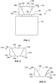
- Figure 5 illustrates a top view of the headrest 120 of Figure 4 , according to an embodiment of the present disclosure.
- the central main body 130 may expand from the front surface 136 towards a rear surface 192.
- each of the first lateral stabilizer 132 and the second lateral stabilizer 134 may recede from respective front surfaces 138 and 140 towards respective rear surfaces 194 and 196.
- Figure 6 illustrates a front view of the headrest of Figures 4 and 5 .
- the first lateral stabilizer 132 is in the retracted position
- the second lateral stabilizer 134 is in the stabilizing position.
- the angled configurations of the first lateral stabilizer 132 and the second lateral stabilizer 134 as shown in Figures 4-6 for example, provide ergonomic, comfortable resting positions when the first lateral stabilizer 132 and the second lateral stabilizer 134 are in stabilizing positions.
- the inner surfaces 153 and 154 outwardly cant from the front surfaces 138 and 140 (as shown in Figure 6 , the second lateral stabilizer 134 is in the stabilizing position and therefore the front surface 140 is oriented downwardly) towards the rear surfaces 194 and 196, which provides an ergonomic contour for resting a head and/or neck against.
- the inner surfaces 153 and 154 may be curved and contoured for additional comfort.
- the ergonomic surfaces shown in Figures 4-6 may be used with any of the embodiments of the present disclosure.
- the ergonomic surfaces shown in Figures 4-6 may be used with respect to the seat assembly 100 shown in Figures 1 and the headrest 120 shown in Figures 2 and 3 .
- Figure 7 illustrates a front view of the central main body 130 of the headrest 120, according to an embodiment of the present disclosure.
- a notch 200 may extend into the central main body 130 proximate a central lateral plane at the top 182.
- the notch 200 is configured to receive and retain portions of a passenger's hair (such as a pony tail). In this manner, the notch 200 is configured to allow the passenger to rest in an ergonomically comfortably position without the head of the passenger being propped forward, such as by portions of hair, for example.
- the notch 200 shown in Figure 7 may be used with respect to any of the embodiments of the present disclosure.
- the central main body 130 shown in Figures 2-6 may include the notch 200.
- Figure 8 illustrates a side view of the headrest 120, according to an embodiment of the present disclosure.
- a collapsible shade 220 may be secured to a top of the headrest 120, such as a top of the central main body 130, the first lateral stabilizer 132, or the second lateral stabilizer 134. In the collapsed position, the shade 220 may be collapsed and retained within a sleeve 222, for example.
- the shade 220 may be accordion-like having a collapsible insert 224 (such as a wire frame or mesh) that is configured to collapse and extend and maintain a desired shape.
- a cover 226 (which may be formed of fabric) is positioned over the insert 224.
- Figure 9 illustrates a side view of the headrest 120 of Figure 8 having the shade 220 in an extended, shading position.
- An individual may grasp the shade 220 and pull the shade 220 into the shading position.
- the shade 220 provides shade for the individual, which may be desired when a seat assembly having the headrest 120 is in an aircraft, for example.
- the shade 220 shown and described with respect to Figures 8 and 9 may be used with any of the embodiments of the present disclosure.
- the headrest 120 shown in Figures 2-7 may include the shade 220 shown and described with respect to Figures 8 and 9 .
- Figure 10 illustrates a top view of the headrest 120, according to an embodiment of the present disclosure.
- lateral shades 240 may be configured to moveably retract and extend from surfaces of the first lateral stabilizer 132 and the second lateral stabilizer 134. As such, lateral shades may be moved to shading positions to provide shade and or privacy.
- the lateral shades 240 may be used with any of the embodiments of the present disclosure.
- Figure 11 illustrates a front view of the headrest 120, according to an embodiment of the present disclosure.
- the first lateral stabilizer 132 and the second lateral stabilizer 134 may include a retractable chin rest 250 which is moveably coupled to inner surfaces thereof.
- the chin rest 250 may be moved to a chin-supporting position when the first lateral stabilizer 132 and/or the second lateral stabilizer 134 is in the stabilizing position.
- the chin rest 250 may telescope or articulate outwardly into the chin-supporting position.
- the chin rest 250 may pivot between a retracted position and the chin-supporting position.
- the chin rest 250 may be a cushioned beam or beams, for example.
- the chin rest 250 may be used with any of the embodiments of the present disclosure.
- Figure 12 illustrates a front perspective view of an aircraft 300.
- the aircraft 300 includes a propulsion system 312 that may include two turbofan engines 314, for example.
- the propulsion system 312 may include more engines 314 than shown.
- the engines 314 are carried by wings 316 of the aircraft 300.
- the engines 314 may be carried by a fuselage 318 and/or an empennage 320.
- the empennage 320 may also support horizontal stabilizers 322 and a vertical stabilizer 324.
- the fuselage 318 of the aircraft 300 defines an internal cabin, which may include a cockpit 330.
- the seat assembly 100 shown in Figure 1 including any of the headrests 120 shown and described in the present application may be used within the aircraft 300, or various other vehicles. Passengers are seated on seat assemblies, such as the seat assembly 100 shown in Figure 1 , within the internal cabin. The passengers may be supported by the headrests 120 of the seat assemblies 100, as shown and described with respect to Figures 1-11 .
- the aircraft 300 may be sized, shaped, and configured other than shown in Figure 12 .
- Embodiments of the present disclosure may be used with various other vehicles other than aircraft.
- the headrests 120 may be used with seat assemblies of land-based vehicles, water-based vehicles, or space-based vehicles.
- embodiments of the present disclosure may be used in settings other than with vehicles.
- individuals may use the headrests 120 with respect to seats, couches, beds, or the like in fixed structures (such as residences, office buildings, and/or the like).
- embodiments of the present disclosure provide headrests that are configured to allow a passenger to be supported in a stable, comfortable position, such as during a flight of a commercial aircraft. Further, embodiments of the present disclosure provide headrests that increase comfort and restfulness of an individual.
- a structure, limitation, or element that is "configured to” perform a task or operation is particularly structurally formed, constructed, or adapted in a manner corresponding to the task or operation.
- an object that is merely capable of being modified to perform the task or operation is not “configured to” perform the task or operation as used herein.
Landscapes
- Engineering & Computer Science (AREA)
- Aviation & Aerospace Engineering (AREA)
- Transportation (AREA)
- Mechanical Engineering (AREA)
- Chair Legs, Seat Parts, And Backrests (AREA)
- Seats For Vehicles (AREA)
Abstract
Description
- Embodiments of the present disclosure generally relate to seat assemblies, and more particularly to headrests of seat assemblies that are configured to provide increased comfort and stability to an individual.
- Commercial aircraft transport passengers between locations. During a flight, passengers within an aircraft are seated. A typical seat assembly within an internal cabin includes a headrest. A passenger may decide to rest and/or sleep during a flight. When passengers rest their heads on the headrest in an upright, seated position, the headrest may not be capable of maintaining the head in a stable position. For example, a passenger's head may slump to a side, which may awaken the passenger, who is trying to sleep.
- Certain headrests on seats of a commercial aircraft include side flaps. However, the side flaps typically do not remain in position. As such, a head of a passenger in a seated position trying to rest may slide off or otherwise disengage from the headrest as the side flap moves to an undesirable position. For example, side flaps may be moved into a desired position by a passenger. However, as a head of a passenger leans on a side flap, the side flap typically flattens, which may cause a passenger's neck to kink and jar the passenger awake. In general, finding a comfortable resting position during a flight may prove a challenge to many individuals.
- A need exists for a headrest of a seat assembly that is configured to allow a passenger to be supported in a stable, comfortable position, such as during a flight of a commercial aircraft. Further, a need exists for a headrest that increases comfort and restfulness of an individual.
- With those needs in mind, certain embodiments of the present disclosure provide a headrest for a seat assembly. In a first aspect, a headrest according to claim 1 is provided.
- The headrest includes a central main body having a first side and a second side that is opposite from the first side. A first lateral stabilizer is moveably coupled to the first side of the central main body. The first lateral stabilizer is distinct from the central main body. A second lateral stabilizer is moveably coupled to the second side of the central main body. The second lateral stabilizer is distinct from the central main body. The first lateral stabilizer and the second lateral stabilizer are movable between retracted positions and stabilizing positions.
- In at least one embodiment, front surfaces of the first lateral stabilizer and the second lateral stabilizer are coplanar with a front surface of the central main body when the first lateral stabilizer and the second lateral stabilizer are in the retracted positions. At least portions of the first lateral stabilizer and the second lateral stabilizer are outwardly away from and in front of a plane of the front surface of the central main body when the first lateral stabilizer and the second lateral stabilizer are in the stabilizing positions.
- In at least one embodiment, the first lateral stabilizer and the second lateral stabilizer are pivotally coupled to the central main body. For example, the first lateral stabilizer and the second lateral stabilizer are pivotally coupled to the central main through one or more pivot axles.
- In at least one embodiment, the first lateral stabilizer and the second lateral stabilizer rotate downwardly into the stabilizing positions to provide lateral barriers on the first side and the second side of the central main body.
- The central main body may be fixed in position in relation to a backrest. In at least one embodiment, the central main body may angle upwardly and outwardly on the first side and the second side from a bottom to a top. Each of the first lateral stabilizer and the second lateral stabilizer may have a wide bottom that outwardly recedes to a narrow top. The central main body may expand from a front surface towards a rear surface. Each of the first lateral stabilizer and the second lateral stabilizer may recede from a front surface towards a rear surface. Inner surfaces of the first lateral stabilizer and the second lateral stabilizer may outwardly cant from front surfaces towards rear surfaces.
- The central main body may include a notch proximate a central lateral plane at a top.
- The headrest may include a collapsible shade. The collapsible shade may be secured to a top of the central main body. The collapsible shade may be secured to one of the first lateral stabilizer or the second lateral stabilizer. One or both of the first lateral stabilizer or the second lateral stabilizer may include a retractable chin rest.
- Further optional features are described in the dependent claims.
- Certain embodiments of the present disclosure provide a seat assembly that includes a base, a seat cushion coupled to the base, a backrest coupled to one or both of the base and the seat cushion, and a headrest coupled to the backrest. The headrest includes a central main body, a first lateral stabilizer, and a second lateral stabilizer, as described herein.
-
-
Figure 1 illustrates a side view of a seat assembly, according to an embodiment of the present disclosure. -
Figure 2 illustrates a perspective front view of a headrest, according to an embodiment of the present disclosure. -
Figure 3 illustrates a perspective front view of the headrest ofFigure 2 having a first lateral stabilizer in a stabilizing position. -
Figure 4 illustrates a front view of the seat assembly, according to an embodiment of the present disclosure. -
Figure 5 illustrates a top view of the headrest ofFigure 4 , according to an embodiment of the present disclosure. -
Figure 6 illustrates a front view of the headrest ofFigures 4 and 5 . -
Figure 7 illustrates a front view of a central main body of the headrest, according to an embodiment of the present disclosure. -
Figure 8 illustrates a side view of the headrest, according to an embodiment of the present disclosure. -
Figure 9 illustrates a side view of the headrest ofFigure 8 having a shade in an extended, shading position. -
Figure 10 illustrates a top view of the headrest, according to an embodiment of the present disclosure. -
Figure 11 illustrates a front view of the headrest, according to an embodiment of the present disclosure. -
Figure 12 illustrates a front perspective view of an aircraft. - The foregoing summary, as well as the following detailed description of certain embodiments will be better understood when read in conjunction with the appended drawings. As used herein, an element or step recited in the singular and preceded by the word "a" or "an" should be understood as not necessarily excluding the plural of the elements or steps. Further, references to "one embodiment" are not intended to be interpreted as excluding the existence of additional embodiments that also incorporate the recited features. Moreover, unless explicitly stated to the contrary, embodiments "comprising" or "having" an element or a plurality of elements having a particular condition may include additional elements not having that condition.
- Certain embodiments of the present disclosure provide a headrest for a seat assembly. The headrest includes a central main body having a first side and a second side that is opposite from the first side. A first lateral stabilizer is moveably coupled to the first side of the central main body. A second lateral stabilizer is moveably coupled to the second side of the central main body. The first lateral stabilizer and the second lateral stabilizer are configured to move between retracted positions, in which front surfaces of the first lateral stabilizer and the second lateral stabilizer are generally flush or otherwise coplanar with a front surface of the central main body, and stabilizing positions, in which at least portions of the first lateral stabilizer and the second lateral stabilizer are moved outwardly away from and in front of a plane of the front surface of the central main body. In at least one embodiment, the first lateral stabilizer and the second lateral stabilizer are pivotally coupled to the central main body.
- In at least one embodiment, the first and second lateral stabilizers are configured to rotate downwardly into the stabilizing positions to provide lateral barriers on sides of the central main body. The lateral barriers provide resting surfaces for a head of an individual. As such, the central main body supports the back of the head, and the lateral barriers limit lateral movement of the head.
-
Figure 1 illustrates a side view of aseat assembly 100, according to an embodiment of the present disclosure. In at least one embodiment, theseat assembly 100 is configured to be secured within an interior cabin of a vehicle, such as a commercial aircraft. In at least one other embodiment, theseat assembly 100 is configured to be positioned within a fixed structure, such as a commercial building or residence. - The
seat assembly 100 includes abase 102, which may includelegs 104 that may be secured totracks 106 within an interior cabin of a vehicle. Thelegs 104 may include fittings, fasteners, or the like that are configured to securely connect thelegs 104 to thetracks 106. Thebase 102 supports aseat cushion 108 and abackrest 110, which includes or is otherwise coupled to aheadrest 120.Armrests 112 may be pivotally secured to thebackrest 110 and/or thebase 102. - The
seat assembly 100 may be sized and shaped differently than shown. For example, thelegs 104 of theseat assembly 100 may not be configured to be secured to tracks within an interior cabin of a vehicle. In at least one embodiment, theseat assembly 100 may include wheels or casters positioned at lower ends of thelegs 104. In at least one embodiment, theseat assembly 100 does not include the legs. For example, theseat assembly 100 may include a single support structure extending downwardly from theseat cushion 108. In at least one other embodiment, thebase 102 may be secured to a structure, such as a wall, bench, or the like, without legs or a support structure. As another example, theseat assembly 100 may not include thearmrests 112. -
Figure 2 illustrates a perspective front view of theheadrest 120, according to an embodiment of the present disclosure. Theheadrest 120 is coupled to, or otherwise forms part of, thebackrest 110 shown and described with respect toFigure 1 . - The
headrest 120 includes a centralmain body 130, a firstlateral stabilizer 132 moveably coupled to the centralmain body 130, and a secondlateral stabilizer 134 moveably coupled to the centralmain body 130. The firstlateral stabilizer 132 and the secondlateral stabilizer 134 are distinct from the centralmain body 130. That is, the firstlateral stabilizer 132 and the secondlateral stabilizer 134 are split or otherwise separated from the centralmain body 130. The centralmain body 130 is fixed in position. For example, the central main body may be fixed in position in relation to the backrest 110 (or form a fixed upper portion of the backrest 110). The firstlateral stabilizer 132 is distinct from the centralmain body 130 and is positioned to afirst side 133 of the centralmain body 130, such as a right side of the centralmain body 130. The secondlateral stabilizer 134 is also distinct from the centralmain body 130 and is positioned to asecond side 135 of the centralmain body 130, such as a left side of the centralmain body 130, opposite from the firstlateral stabilizer 132. - The central
main body 130 includes afront surface 136 that is configured to support a rear portion of a head of an individual. As shown inFigure 2 , the firstlateral stabilizer 132 and the secondlateral stabilizer 134 are in retracted positions. In the retracted positions, the firstlateral stabilizer 132 and the secondlateral stabilizer 134 include respectivefront surfaces -
Figure 3 illustrates a perspective front view of theheadrest 120 ofFigure 2 having the firstlateral stabilizer 132 in a stabilizing position. The firstlateral stabilizer 132 is moveably coupled to the centralmain body 130, such as via apivot axle 150. Similarly, the secondlateral stabilizer 134 is moveably coupled to the centralmain body 130, such as via apivot axle 152. The pivot axles 150 and 152 may be coaxial. In at least one embodiment, a single pivot axle extends through the centralmain body 130 and pivotally couples both the firstlateral stabilizer 132 and the secondlateral stabilizer 134 to the centralmain body 130. - As shown, the
pivot axles main body 130 and are pivotally retained within reciprocal bearings of the firstlateral stabilizer 132 and the secondlateral stabilizer 134, respectively. Optionally, thepivot axles lateral stabilizer 132 and the secondlateral stabilizer 134, respectively, and be pivotally retained within reciprocal bearings onopposite sides main body 130. - Each of the first
lateral stabilizer 132 and the secondlateral stabilizer 134 are configured to pivot about therespective pivot axles Figure 2 , and stabilizing positions (the firstlateral stabilizer 132 is shown in the stabilizing position inFigure 3 ). In the stabilizing positions, thefront surfaces lateral stabilizer 134 are oriented towards a downward direction. In the stabilizing positions,inner surfaces lateral stabilizer 132 and the secondlateral stabilizer 134 are configured to provide lateral barriers that limit side-to-side motion of a head of an individual, thereby laterally stabilizing the head. Theinner surfaces - Referring to
Figures 2, and 3 , the firstlateral stabilizer 132 and the secondlateral stabilizer 134 are configured to move between the retracted positions, in which thefront surfaces lateral stabilizer 132 and the secondlateral stabilizer 134 are generally flush or otherwise coplanar with thefront surface 136 of the centralmain body 130, and the stabilizing positions, in which respectivetop portions intermediate portions lateral stabilizer 132 and the secondlateral stabilizer 134 are moved outwardly away and in front of aplane 170 in which thefront surface 136 of the centralmain body 130 resides. - As shown, the first and second
lateral stabilizers respective sides main body 130. The lateral barriers provide resting surfaces for a head of an individual. As such, the centralmain body 130 supports the back of the head, and the lateral barriers defined by the first and secondlateral stabilizers -
Figure 4 illustrates a front view of theseat assembly 100, according to an embodiment of the present disclosure. As shown, the centralmain body 130 angles upwardly and outwardly on bothsides lateral stabilizer 132 and the secondlateral stabilizer 134 have awide bottom narrow top -
Figure 5 illustrates a top view of theheadrest 120 ofFigure 4 , according to an embodiment of the present disclosure. The centralmain body 130 may expand from thefront surface 136 towards arear surface 192. Conversely, each of the firstlateral stabilizer 132 and the secondlateral stabilizer 134 may recede from respectivefront surfaces rear surfaces -
Figure 6 illustrates a front view of the headrest ofFigures 4 and 5 . As shown inFigure 6 , the firstlateral stabilizer 132 is in the retracted position, and the secondlateral stabilizer 134 is in the stabilizing position. The angled configurations of the firstlateral stabilizer 132 and the secondlateral stabilizer 134 as shown inFigures 4-6 , for example, provide ergonomic, comfortable resting positions when the firstlateral stabilizer 132 and the secondlateral stabilizer 134 are in stabilizing positions. For example, as shown, theinner surfaces front surfaces 138 and 140 (as shown inFigure 6 , the secondlateral stabilizer 134 is in the stabilizing position and therefore thefront surface 140 is oriented downwardly) towards therear surfaces inner surfaces - The ergonomic surfaces shown in
Figures 4-6 may be used with any of the embodiments of the present disclosure. For example, the ergonomic surfaces shown inFigures 4-6 may be used with respect to theseat assembly 100 shown inFigures 1 and theheadrest 120 shown inFigures 2 and 3 . -
Figure 7 illustrates a front view of the centralmain body 130 of theheadrest 120, according to an embodiment of the present disclosure. Anotch 200 may extend into the centralmain body 130 proximate a central lateral plane at the top 182. Thenotch 200 is configured to receive and retain portions of a passenger's hair (such as a pony tail). In this manner, thenotch 200 is configured to allow the passenger to rest in an ergonomically comfortably position without the head of the passenger being propped forward, such as by portions of hair, for example. - The
notch 200 shown inFigure 7 may be used with respect to any of the embodiments of the present disclosure. For example, the centralmain body 130 shown inFigures 2-6 may include thenotch 200. -
Figure 8 illustrates a side view of theheadrest 120, according to an embodiment of the present disclosure. Acollapsible shade 220 may be secured to a top of theheadrest 120, such as a top of the centralmain body 130, the firstlateral stabilizer 132, or the secondlateral stabilizer 134. In the collapsed position, theshade 220 may be collapsed and retained within asleeve 222, for example. - The
shade 220 may be accordion-like having a collapsible insert 224 (such as a wire frame or mesh) that is configured to collapse and extend and maintain a desired shape. A cover 226 (which may be formed of fabric) is positioned over theinsert 224. -
Figure 9 illustrates a side view of theheadrest 120 ofFigure 8 having theshade 220 in an extended, shading position. An individual may grasp theshade 220 and pull theshade 220 into the shading position. In the shading position, theshade 220 provides shade for the individual, which may be desired when a seat assembly having theheadrest 120 is in an aircraft, for example. - The
shade 220 shown and described with respect toFigures 8 and 9 may be used with any of the embodiments of the present disclosure. For example, theheadrest 120 shown inFigures 2-7 may include theshade 220 shown and described with respect toFigures 8 and 9 . -
Figure 10 illustrates a top view of theheadrest 120, according to an embodiment of the present disclosure. As shown,lateral shades 240 may be configured to moveably retract and extend from surfaces of the firstlateral stabilizer 132 and the secondlateral stabilizer 134. As such, lateral shades may be moved to shading positions to provide shade and or privacy. The lateral shades 240 may be used with any of the embodiments of the present disclosure. -
Figure 11 illustrates a front view of theheadrest 120, according to an embodiment of the present disclosure. In this embodiment, one or both of the firstlateral stabilizer 132 and the secondlateral stabilizer 134 may include aretractable chin rest 250 which is moveably coupled to inner surfaces thereof. Thechin rest 250 may be moved to a chin-supporting position when the firstlateral stabilizer 132 and/or the secondlateral stabilizer 134 is in the stabilizing position. Thechin rest 250 may telescope or articulate outwardly into the chin-supporting position. As another option, thechin rest 250 may pivot between a retracted position and the chin-supporting position. Thechin rest 250 may be a cushioned beam or beams, for example. Thechin rest 250 may be used with any of the embodiments of the present disclosure. -
Figure 12 illustrates a front perspective view of anaircraft 300. Theaircraft 300 includes apropulsion system 312 that may include twoturbofan engines 314, for example. Optionally, thepropulsion system 312 may includemore engines 314 than shown. Theengines 314 are carried bywings 316 of theaircraft 300. In other embodiments, theengines 314 may be carried by afuselage 318 and/or anempennage 320. Theempennage 320 may also supporthorizontal stabilizers 322 and avertical stabilizer 324. Thefuselage 318 of theaircraft 300 defines an internal cabin, which may include acockpit 330. - The
seat assembly 100 shown inFigure 1 including any of theheadrests 120 shown and described in the present application may be used within theaircraft 300, or various other vehicles. Passengers are seated on seat assemblies, such as theseat assembly 100 shown inFigure 1 , within the internal cabin. The passengers may be supported by theheadrests 120 of theseat assemblies 100, as shown and described with respect toFigures 1-11 . Theaircraft 300 may be sized, shaped, and configured other than shown inFigure 12 . - Embodiments of the present disclosure may be used with various other vehicles other than aircraft. For example, the
headrests 120 may be used with seat assemblies of land-based vehicles, water-based vehicles, or space-based vehicles. Further, embodiments of the present disclosure may be used in settings other than with vehicles. For example, individuals may use theheadrests 120 with respect to seats, couches, beds, or the like in fixed structures (such as residences, office buildings, and/or the like). - As described herein, embodiments of the present disclosure provide headrests that are configured to allow a passenger to be supported in a stable, comfortable position, such as during a flight of a commercial aircraft. Further, embodiments of the present disclosure provide headrests that increase comfort and restfulness of an individual.
- While various spatial and directional terms, such as top, bottom, lower, mid, lateral, horizontal, vertical, front and the like may be used to describe embodiments of the present disclosure, it is understood that such terms are merely used with respect to the orientations shown in the drawings. The orientations may be inverted, rotated, or otherwise changed, such that an upper portion is a lower portion, and vice versa, horizontal becomes vertical, and the like.
- As used herein, a structure, limitation, or element that is "configured to" perform a task or operation is particularly structurally formed, constructed, or adapted in a manner corresponding to the task or operation. For purposes of clarity and the avoidance of doubt, an object that is merely capable of being modified to perform the task or operation is not "configured to" perform the task or operation as used herein.
- It is to be understood that the above description is intended to be illustrative, and not restrictive. For example, the above-described embodiments (and/or aspects thereof) may be used in combination with each other. In addition, many modifications may be made to adapt a particular situation or material to the teachings of the various embodiments of the disclosure without departing from their scope. While the dimensions and types of materials described herein are intended to define the parameters of the various embodiments of the disclosure, the embodiments are by no means limiting and are exemplary embodiments. Many other embodiments will be apparent to those of skill in the art upon reviewing the above description. The scope of the various embodiments of the disclosure should, therefore, be determined with reference to the appended claims, along with the full scope of equivalents to which such claims are entitled. In the appended claims, the terms "including" and "in which" are used as the plain-English equivalents of the respective terms "comprising" and "wherein." Moreover, the terms "first," "second," and "third," etc. are used merely as labels, and are not intended to impose numerical requirements on their objects. Further, the limitations of the following claims are not written in means-plus-function format and are not intended to be interpreted based on 35 U.S.C. § 112(f), unless and until such claim limitations expressly use the phrase "means for" followed by a statement of function void of further structure.
- Further, the disclosure comprises embodiments according to the following clauses:
- Clause 1. A headrest for a seat assembly, the headrest comprising:
- a central main body having a first side and a second side that is opposite from the first side;
- a first lateral stabilizer moveably coupled to the first side of the central main body, wherein the first lateral stabilizer is distinct from the central main body; and
- a second lateral stabilizer moveably coupled to the second side of the central main body, wherein the second lateral stabilizer is distinct from the central main body,
- wherein the first lateral stabilizer and the second lateral stabilizer are movable between retracted positions and stabilizing positions.
- Clause 2. The headrest of clause 1, wherein front surfaces of the first lateral stabilizer and the second lateral stabilizer are coplanar with a front surface of the central main body when the first lateral stabilizer and the second lateral stabilizer are in the retracted positions.
- Clause 3. The headrest of clause 2, wherein at least portions of the first lateral stabilizer and the second lateral stabilizer are outwardly away from and in front of a plane of the front surface of the central main body when the first lateral stabilizer and the second lateral stabilizer are in the stabilizing positions.
- Clause 4. The headrest of any of clauses 1-3, wherein the first lateral stabilizer and the second lateral stabilizer are pivotally coupled to the central main body.
- Clause 5. The headrest of any of clauses 1-4, wherein the first lateral stabilizer and the second lateral stabilizer are pivotally coupled to the central main through one or more pivot axles.
- Clause 6. The headrest of any of clauses 1-5, wherein the first lateral stabilizer and the second lateral stabilizer rotate downwardly into the stabilizing positions to provide lateral barriers on the first side and the second side of the central main body.
- Clause 7. The headrest of any of clauses 1-6, wherein the central main body is fixed in position in relation to a backrest.
- Clause 8. The headrest of any of clauses 1-7, wherein the central main body angles upwardly and outwardly on the first side and the second side from a bottom to a top, and wherein each of the first lateral stabilizer and the second lateral stabilizer has a wide bottom that outwardly recedes to a narrow top.
- Clause 9. The headrest of any of clauses 1-8, wherein the central main body expands from a front surface towards a rear surface, and wherein each of the first lateral stabilizer and the second lateral stabilizer recedes from a front surface towards a rear surface.
- Clause 10. The headrest of any of clauses 1-9, wherein inner surfaces of the first lateral stabilizer and the second lateral stabilizer outwardly cant from front surfaces towards rear surfaces.
- Clause 11. The headrest of any of clauses 1-10, wherein the central main body comprises a notch proximate a central lateral plane at a top.
- Clause 12. The headrest of any of clauses 1-11, further comprising a collapsible shade.
- Clause 13. The headrest of clause 12, wherein the collapsible shade is secured to a top of the central main body.
- Clause 14. The headrest of any of clauses 12-13, wherein the collapsible shade is secured to one of the first lateral stabilizer or the second lateral stabilizer.
- Clause 15. The headrest of any of clauses 1-14, wherein one or both of the first lateral stabilizer or the second lateral stabilizer comprise a retractable chin rest.
- Clause 16. A seat assembly comprising:
- a base;
- a seat cushion coupled to the base;
- a backrest coupled to one or both of the base and the seat cushion; and
- a headrest coupled to the backrest, wherein the headrest comprises:
- a central main body having a first side and a second side that is opposite from the first side, wherein the central main body is fixed in position in relation to a backrest;
- a first lateral stabilizer pivotally coupled to the first side of the central main body, wherein the first lateral stabilizer is distinct from the central main body; and
- a second lateral stabilizer pivotally coupled to the second side of the central main body, wherein the second lateral stabilizer is distinct from the central main body,
- wherein the first lateral stabilizer and the second lateral stabilizer are movable between retracted positions and stabilizing positions,
- wherein front surfaces of the first lateral stabilizer and the second lateral stabilizer are coplanar with a front surface of the central main body when the first lateral stabilizer and the second lateral stabilizer are in the retracted positions,
- wherein at least portions of the first lateral stabilizer and the second lateral stabilizer are outwardly away from and in front of a plane of the front surface of the central main body when the first lateral stabilizer and the second lateral stabilizer are in the stabilizing positions,
- wherein the first lateral stabilizer and the second lateral stabilizer rotate downwardly into the stabilizing positions to provide lateral barriers on the first side and the second side of the central main body.
- Clause 17. The seat assembly of clause 16, wherein the central main body angles upwardly and outwardly on the first side and the second side from a bottom to a top, wherein each of the first lateral stabilizer and the second lateral stabilizer has a wide bottom that outwardly recedes to a narrow top, wherein the central main body expands from a front surface towards a rear surface, wherein each of the first lateral stabilizer and the second lateral stabilizer recedes from a front surface towards a rear surface.
- Clause 18. The seat assembly of any of clauses 16-17, wherein the central main body comprises a notch proximate a central lateral plane at a top.
- Clause 19. The seat assembly of any of clauses 16-18, wherein the headrest further comprises a collapsible shade.
- Clause 20. The seat assembly of any of clauses 16-19, wherein one or both of the first lateral stabilizer or the second lateral stabilizer comprise a retractable chin rest.
- This written description uses examples to disclose the various embodiments of the disclosure, including the best mode, and also to enable any person skilled in the art to practice the various embodiments of the disclosure, including making and using any devices or systems and performing any incorporated methods. The patentable scope of the various embodiments of the disclosure is defined by the claims, and may include other examples that occur to those skilled in the art. Such other examples are intended to be within the scope of the claims if the examples have structural elements that do not differ from the literal language of the claims, or if the examples include equivalent structural elements with insubstantial differences from the literal language of the claims.
Claims (15)
- A headrest (120) for a seat assembly (100), the headrest (120) comprising:a central main body (130) having a first side (133) and a second side (135) that is opposite from the first side (133);a first lateral stabilizer (132) moveably coupled to the first side (133) of the central main body (130), wherein the first lateral stabilizer (132) is distinct from the central main body (130); anda second lateral stabilizer (134) moveably coupled to the second side (135) of the central main body (130), wherein the second lateral stabilizer (134) is distinct from the central main body (130),wherein the first lateral stabilizer (132) and the second lateral stabilizer (134) are movable between retracted positions and stabilizing positions.
- The headrest (120) of claim 1, wherein front surfaces (138, 140) of the first lateral stabilizer (132) and the second lateral stabilizer (134) are coplanar with a front surface (136) of the central main body (130) when the first lateral stabilizer (132) and the second lateral stabilizer (134) are in the retracted positions.
- The headrest (120) of claim 2, wherein at least portions of the first lateral stabilizer (132) and the second lateral stabilizer (134) are outwardly away from and in front of a plane (170) of the front surface (136) of the central main body (130) when the first lateral stabilizer (132) and the second lateral stabilizer (134) are in the stabilizing positions.
- The headrest (120) of any of claims 1-3, wherein the first lateral stabilizer (132) and the second lateral stabilizer (134) are pivotally coupled to the central main body (130).
- The headrest (120) of any of claims 1-4, wherein the first lateral stabilizer (132) and the second lateral stabilizer (134) are pivotally coupled to the central main through one or more pivot axles (150, 152).
- The headrest (120) of any of claims 1-5, wherein the first lateral stabilizer (132) and the second lateral stabilizer (134) rotate downwardly into the stabilizing positions to provide lateral barriers on the first side (133) and the second side (135) of the central main body (130).
- The headrest (120) of any of claims 1-6, wherein the central main body (130) is fixed in position in relation to a backrest (110).
- The headrest (120) of any of claims 1-7, wherein the central main body (130) angles upwardly and outwardly on the first side (133) and the second side (135) from a bottom (180) to a top (182), and wherein each of the first lateral stabilizer (132) and the second lateral stabilizer (134) has a wide bottom (184, 186, 180) that outwardly recedes to a narrow top (182, 188, 190).
- The headrest (120) of any of claims 1-8, wherein the central main body (130) expands from a front surface (136) towards a rear surface (192), and wherein each of the first lateral stabilizer (132) and the second lateral stabilizer (134) recedes from a front surface (138, 140) towards a rear surface (194, 196).
- The headrest (120) of any of claims 1-9, wherein inner surfaces (153, 154) of the first lateral stabilizer (132) and the second lateral stabilizer (134) outwardly cant from front surfaces (138, 140) towards rear surfaces (194, 196).
- The headrest (120) of any of claims 1-10, wherein the central main body (130) comprises a notch (200) proximate a central lateral plane (170) at a top (182).
- The headrest (12) of any of claims 1-11, further comprising a collapsible shade (220), wherein the collapsible shade (220) is secured to a top (182) of the central main body (130).
- The headrest (120) of claim 12, wherein the collapsible shade (220) is secured to one of the first lateral stabilizer (132) or the second lateral stabilizer (134).
- The headrest (120) of any of claims 1-13, wherein one or both of the first lateral stabilizer (132) or the second lateral stabilizer (134) comprise a retractable chin rest (250).
- The headrest (120) of any of claims 1-14 within a seat assembly (100), the seat assembly (100) comprising:a base (102);a seat cushion (108) coupled to the base (102);a backrest (110) coupled to one or both of the base (102) and the seat cushion (108); andthe headrest (120) coupled to the backrest (110).
Applications Claiming Priority (1)
| Application Number | Priority Date | Filing Date | Title |
|---|---|---|---|
| US16/289,736 US10953988B2 (en) | 2019-03-01 | 2019-03-01 | Head stabilizing headrest |
Publications (2)
| Publication Number | Publication Date |
|---|---|
| EP3702283A1 true EP3702283A1 (en) | 2020-09-02 |
| EP3702283B1 EP3702283B1 (en) | 2022-06-22 |
Family
ID=69726511
Family Applications (1)
| Application Number | Title | Priority Date | Filing Date |
|---|---|---|---|
| EP20159114.6A Active EP3702283B1 (en) | 2019-03-01 | 2020-02-24 | Head stabilizing headrest |
Country Status (3)
| Country | Link |
|---|---|
| US (1) | US10953988B2 (en) |
| EP (1) | EP3702283B1 (en) |
| BR (1) | BR102020003588A2 (en) |
Families Citing this family (1)
| Publication number | Priority date | Publication date | Assignee | Title |
|---|---|---|---|---|
| US12434842B2 (en) * | 2023-10-18 | 2025-10-07 | B/E Aerospace, Inc. | Headrest with deployable oblique supports |
Citations (5)
| Publication number | Priority date | Publication date | Assignee | Title |
|---|---|---|---|---|
| GB2302268A (en) * | 1995-06-14 | 1997-01-15 | Autoliv Dev | Head rest with lateral restraint |
| DE202009005915U1 (en) * | 2009-04-21 | 2009-09-10 | Kieslich Industries Administration Gmbh | Headrest for passenger seats in passenger cars and / or trucks with integrated comfort head rest |
| KR20120058011A (en) * | 2010-11-29 | 2012-06-07 | 김원배 | A head rest with hair insert space |
| DE102013001336A1 (en) * | 2013-01-26 | 2014-07-31 | Joachim Bofinger | Headrest for vehicle seat that is arranged in e.g. motor car, has opposite support pads supporting head of person in side regions, arranged at front ends of neck pad and secured at carrier element |
| DE102017107153A1 (en) * | 2017-04-03 | 2018-10-04 | Recaro Aircraft Seating Gmbh & Co. Kg | Seat device, in particular aircraft seat device |
Family Cites Families (14)
| Publication number | Priority date | Publication date | Assignee | Title |
|---|---|---|---|---|
| US4205878A (en) * | 1978-08-02 | 1980-06-03 | Wooten James D | Pull out headrest |
| JPH0638703U (en) * | 1992-11-09 | 1994-05-24 | 三菱自動車工業株式会社 | Vehicle seat |
| US5370446A (en) * | 1993-12-10 | 1994-12-06 | Bancod; Ludovico E. | Headrest with side supports |
| JPH09254690A (en) * | 1996-03-21 | 1997-09-30 | Delta Kogyo Co Ltd | Shading device for automobile |
| DE29712497U1 (en) * | 1997-07-15 | 1997-09-11 | Kiddy GmbH Autokindersitze, 07356 Thimmendorf | Child seat to be placed on a vehicle seat |
| US6942297B2 (en) | 2001-08-17 | 2005-09-13 | Eric Eugene Johnson | Portable lateral-support headrest |
| DE10349929A1 (en) * | 2002-10-26 | 2004-07-29 | Christian Beer | Neck support for attachment to a seat heat rest, especially for motor vehicle travel, comprises two side arm cushions that can be lowered from the head rest and can incorporate a microphone for a hands-free speech system |
| US20040158924A1 (en) * | 2003-01-31 | 2004-08-19 | Frandsen-Anderson Sherl Frances | Methods and systems for deploying a fire safety blanket |
| US8096613B2 (en) * | 2009-07-15 | 2012-01-17 | Meeker R&D | Head retaining foam liner for car seat |
| EP3122632B1 (en) * | 2014-03-28 | 2022-07-20 | B/E Aerospace, Inc. | Aircraft seat with segmented seatback for achieving in-bed lounge sitting position |
| US9481277B1 (en) * | 2015-09-23 | 2016-11-01 | Ford Global Technologies, Llc | Adjustable headrest |
| WO2017118868A1 (en) * | 2016-01-07 | 2017-07-13 | Mueller Thomas R A | Passenger seat comprising tiltable sections of its headrest |
| FR3047157A1 (en) * | 2016-02-01 | 2017-08-04 | Turrilot Manuel | ARMCHAIR WITH HOLES FOR THE HEAD |
| US10399475B2 (en) * | 2017-12-07 | 2019-09-03 | Ford Global Technologies, Llc | Headrest with deployable neck pillow feature |
-
2019
- 2019-03-01 US US16/289,736 patent/US10953988B2/en not_active Expired - Fee Related
-
2020
- 2020-02-20 BR BR102020003588-6A patent/BR102020003588A2/en active Search and Examination
- 2020-02-24 EP EP20159114.6A patent/EP3702283B1/en active Active
Patent Citations (5)
| Publication number | Priority date | Publication date | Assignee | Title |
|---|---|---|---|---|
| GB2302268A (en) * | 1995-06-14 | 1997-01-15 | Autoliv Dev | Head rest with lateral restraint |
| DE202009005915U1 (en) * | 2009-04-21 | 2009-09-10 | Kieslich Industries Administration Gmbh | Headrest for passenger seats in passenger cars and / or trucks with integrated comfort head rest |
| KR20120058011A (en) * | 2010-11-29 | 2012-06-07 | 김원배 | A head rest with hair insert space |
| DE102013001336A1 (en) * | 2013-01-26 | 2014-07-31 | Joachim Bofinger | Headrest for vehicle seat that is arranged in e.g. motor car, has opposite support pads supporting head of person in side regions, arranged at front ends of neck pad and secured at carrier element |
| DE102017107153A1 (en) * | 2017-04-03 | 2018-10-04 | Recaro Aircraft Seating Gmbh & Co. Kg | Seat device, in particular aircraft seat device |
Also Published As
| Publication number | Publication date |
|---|---|
| US20200277060A1 (en) | 2020-09-03 |
| US10953988B2 (en) | 2021-03-23 |
| EP3702283B1 (en) | 2022-06-22 |
| BR102020003588A2 (en) | 2020-10-27 |
Similar Documents
| Publication | Publication Date | Title |
|---|---|---|
| EP3572325B1 (en) | Deployable partition systems and methods for seat assemblies | |
| US11021255B2 (en) | Work-and-dine aircraft seat with tilt and shift articulation | |
| EP3060472B1 (en) | Linearly deployable aircraft seat legrest | |
| US10773626B2 (en) | Adjustable headrest enabling sideward leaning and seclusion | |
| US10696410B2 (en) | Seat assembly having a deployable headrest | |
| US10525858B2 (en) | Deployable neck support disposed within an interior of a headrest | |
| EP3702283A1 (en) | Head stabilizing headrest | |
| US20200307806A1 (en) | Seat adjustment system and method | |
| US12071244B2 (en) | Reconfigurable seat assembly | |
| US10450072B2 (en) | Seatback articulation assembly and method | |
| US11312495B2 (en) | Compact seat assembly for a vehicle | |
| US20230234709A1 (en) | Seat assembly having stablization system | |
| US20230111420A1 (en) | Reclinable seat with multiple configurations | |
| US10926881B2 (en) | Seat adjustment system and method | |
| US20240253789A1 (en) | Transformable seat systems and methods for an internal cabin of an aircraft | |
| US20240051665A1 (en) | Adjustable width passenger seat | |
| US11866176B2 (en) | Variable reclination backrest for a seat assembly | |
| US11254434B2 (en) | Headrest for a seat | |
| CA3093168C (en) | Headrest for a seat |
Legal Events
| Date | Code | Title | Description |
|---|---|---|---|
| PUAI | Public reference made under article 153(3) epc to a published international application that has entered the european phase |
Free format text: ORIGINAL CODE: 0009012 |
|
| STAA | Information on the status of an ep patent application or granted ep patent |
Free format text: STATUS: THE APPLICATION HAS BEEN PUBLISHED |
|
| AK | Designated contracting states |
Kind code of ref document: A1 Designated state(s): AL AT BE BG CH CY CZ DE DK EE ES FI FR GB GR HR HU IE IS IT LI LT LU LV MC MK MT NL NO PL PT RO RS SE SI SK SM TR |
|
| AX | Request for extension of the european patent |
Extension state: BA ME |
|
| STAA | Information on the status of an ep patent application or granted ep patent |
Free format text: STATUS: REQUEST FOR EXAMINATION WAS MADE |
|
| 17P | Request for examination filed |
Effective date: 20210226 |
|
| RBV | Designated contracting states (corrected) |
Designated state(s): AL AT BE BG CH CY CZ DE DK EE ES FI FR GB GR HR HU IE IS IT LI LT LU LV MC MK MT NL NO PL PT RO RS SE SI SK SM TR |
|
| GRAP | Despatch of communication of intention to grant a patent |
Free format text: ORIGINAL CODE: EPIDOSNIGR1 |
|
| STAA | Information on the status of an ep patent application or granted ep patent |
Free format text: STATUS: GRANT OF PATENT IS INTENDED |
|
| INTG | Intention to grant announced |
Effective date: 20211122 |
|
| GRAJ | Information related to disapproval of communication of intention to grant by the applicant or resumption of examination proceedings by the epo deleted |
Free format text: ORIGINAL CODE: EPIDOSDIGR1 |
|
| STAA | Information on the status of an ep patent application or granted ep patent |
Free format text: STATUS: REQUEST FOR EXAMINATION WAS MADE |
|
| GRAP | Despatch of communication of intention to grant a patent |
Free format text: ORIGINAL CODE: EPIDOSNIGR1 |
|
| STAA | Information on the status of an ep patent application or granted ep patent |
Free format text: STATUS: GRANT OF PATENT IS INTENDED |
|
| INTC | Intention to grant announced (deleted) | ||
| INTG | Intention to grant announced |
Effective date: 20220321 |
|
| GRAS | Grant fee paid |
Free format text: ORIGINAL CODE: EPIDOSNIGR3 |
|
| GRAA | (expected) grant |
Free format text: ORIGINAL CODE: 0009210 |
|
| STAA | Information on the status of an ep patent application or granted ep patent |
Free format text: STATUS: THE PATENT HAS BEEN GRANTED |
|
| AK | Designated contracting states |
Kind code of ref document: B1 Designated state(s): AL AT BE BG CH CY CZ DE DK EE ES FI FR GB GR HR HU IE IS IT LI LT LU LV MC MK MT NL NO PL PT RO RS SE SI SK SM TR |
|
| REG | Reference to a national code |
Ref country code: GB Ref legal event code: FG4D |
|
| REG | Reference to a national code |
Ref country code: CH Ref legal event code: EP |
|
| REG | Reference to a national code |
Ref country code: DE Ref legal event code: R096 Ref document number: 602020003599 Country of ref document: DE |
|
| REG | Reference to a national code |
Ref country code: AT Ref legal event code: REF Ref document number: 1499639 Country of ref document: AT Kind code of ref document: T Effective date: 20220715 |
|
| REG | Reference to a national code |
Ref country code: IE Ref legal event code: FG4D |
|
| REG | Reference to a national code |
Ref country code: LT Ref legal event code: MG9D |
|
| REG | Reference to a national code |
Ref country code: NL Ref legal event code: MP Effective date: 20220622 |
|
| PG25 | Lapsed in a contracting state [announced via postgrant information from national office to epo] |
Ref country code: SE Free format text: LAPSE BECAUSE OF FAILURE TO SUBMIT A TRANSLATION OF THE DESCRIPTION OR TO PAY THE FEE WITHIN THE PRESCRIBED TIME-LIMIT Effective date: 20220622 Ref country code: NO Free format text: LAPSE BECAUSE OF FAILURE TO SUBMIT A TRANSLATION OF THE DESCRIPTION OR TO PAY THE FEE WITHIN THE PRESCRIBED TIME-LIMIT Effective date: 20220922 Ref country code: LT Free format text: LAPSE BECAUSE OF FAILURE TO SUBMIT A TRANSLATION OF THE DESCRIPTION OR TO PAY THE FEE WITHIN THE PRESCRIBED TIME-LIMIT Effective date: 20220622 Ref country code: HR Free format text: LAPSE BECAUSE OF FAILURE TO SUBMIT A TRANSLATION OF THE DESCRIPTION OR TO PAY THE FEE WITHIN THE PRESCRIBED TIME-LIMIT Effective date: 20220622 Ref country code: GR Free format text: LAPSE BECAUSE OF FAILURE TO SUBMIT A TRANSLATION OF THE DESCRIPTION OR TO PAY THE FEE WITHIN THE PRESCRIBED TIME-LIMIT Effective date: 20220923 Ref country code: FI Free format text: LAPSE BECAUSE OF FAILURE TO SUBMIT A TRANSLATION OF THE DESCRIPTION OR TO PAY THE FEE WITHIN THE PRESCRIBED TIME-LIMIT Effective date: 20220622 Ref country code: BG Free format text: LAPSE BECAUSE OF FAILURE TO SUBMIT A TRANSLATION OF THE DESCRIPTION OR TO PAY THE FEE WITHIN THE PRESCRIBED TIME-LIMIT Effective date: 20220922 |
|
| REG | Reference to a national code |
Ref country code: AT Ref legal event code: MK05 Ref document number: 1499639 Country of ref document: AT Kind code of ref document: T Effective date: 20220622 |
|
| PG25 | Lapsed in a contracting state [announced via postgrant information from national office to epo] |
Ref country code: RS Free format text: LAPSE BECAUSE OF FAILURE TO SUBMIT A TRANSLATION OF THE DESCRIPTION OR TO PAY THE FEE WITHIN THE PRESCRIBED TIME-LIMIT Effective date: 20220622 Ref country code: LV Free format text: LAPSE BECAUSE OF FAILURE TO SUBMIT A TRANSLATION OF THE DESCRIPTION OR TO PAY THE FEE WITHIN THE PRESCRIBED TIME-LIMIT Effective date: 20220622 |
|
| PG25 | Lapsed in a contracting state [announced via postgrant information from national office to epo] |
Ref country code: NL Free format text: LAPSE BECAUSE OF FAILURE TO SUBMIT A TRANSLATION OF THE DESCRIPTION OR TO PAY THE FEE WITHIN THE PRESCRIBED TIME-LIMIT Effective date: 20220622 |
|
| PG25 | Lapsed in a contracting state [announced via postgrant information from national office to epo] |
Ref country code: SM Free format text: LAPSE BECAUSE OF FAILURE TO SUBMIT A TRANSLATION OF THE DESCRIPTION OR TO PAY THE FEE WITHIN THE PRESCRIBED TIME-LIMIT Effective date: 20220622 Ref country code: SK Free format text: LAPSE BECAUSE OF FAILURE TO SUBMIT A TRANSLATION OF THE DESCRIPTION OR TO PAY THE FEE WITHIN THE PRESCRIBED TIME-LIMIT Effective date: 20220622 Ref country code: RO Free format text: LAPSE BECAUSE OF FAILURE TO SUBMIT A TRANSLATION OF THE DESCRIPTION OR TO PAY THE FEE WITHIN THE PRESCRIBED TIME-LIMIT Effective date: 20220622 Ref country code: PT Free format text: LAPSE BECAUSE OF FAILURE TO SUBMIT A TRANSLATION OF THE DESCRIPTION OR TO PAY THE FEE WITHIN THE PRESCRIBED TIME-LIMIT Effective date: 20221024 Ref country code: ES Free format text: LAPSE BECAUSE OF FAILURE TO SUBMIT A TRANSLATION OF THE DESCRIPTION OR TO PAY THE FEE WITHIN THE PRESCRIBED TIME-LIMIT Effective date: 20220622 Ref country code: EE Free format text: LAPSE BECAUSE OF FAILURE TO SUBMIT A TRANSLATION OF THE DESCRIPTION OR TO PAY THE FEE WITHIN THE PRESCRIBED TIME-LIMIT Effective date: 20220622 Ref country code: CZ Free format text: LAPSE BECAUSE OF FAILURE TO SUBMIT A TRANSLATION OF THE DESCRIPTION OR TO PAY THE FEE WITHIN THE PRESCRIBED TIME-LIMIT Effective date: 20220622 Ref country code: AT Free format text: LAPSE BECAUSE OF FAILURE TO SUBMIT A TRANSLATION OF THE DESCRIPTION OR TO PAY THE FEE WITHIN THE PRESCRIBED TIME-LIMIT Effective date: 20220622 |
|
| PG25 | Lapsed in a contracting state [announced via postgrant information from national office to epo] |
Ref country code: PL Free format text: LAPSE BECAUSE OF FAILURE TO SUBMIT A TRANSLATION OF THE DESCRIPTION OR TO PAY THE FEE WITHIN THE PRESCRIBED TIME-LIMIT Effective date: 20220622 Ref country code: IS Free format text: LAPSE BECAUSE OF FAILURE TO SUBMIT A TRANSLATION OF THE DESCRIPTION OR TO PAY THE FEE WITHIN THE PRESCRIBED TIME-LIMIT Effective date: 20221022 |
|
| RAP4 | Party data changed (patent owner data changed or rights of a patent transferred) |
Owner name: THE BOEING COMPANY |
|
| REG | Reference to a national code |
Ref country code: DE Ref legal event code: R097 Ref document number: 602020003599 Country of ref document: DE |
|
| PG25 | Lapsed in a contracting state [announced via postgrant information from national office to epo] |
Ref country code: AL Free format text: LAPSE BECAUSE OF FAILURE TO SUBMIT A TRANSLATION OF THE DESCRIPTION OR TO PAY THE FEE WITHIN THE PRESCRIBED TIME-LIMIT Effective date: 20220622 |
|
| PG25 | Lapsed in a contracting state [announced via postgrant information from national office to epo] |
Ref country code: DK Free format text: LAPSE BECAUSE OF FAILURE TO SUBMIT A TRANSLATION OF THE DESCRIPTION OR TO PAY THE FEE WITHIN THE PRESCRIBED TIME-LIMIT Effective date: 20220622 |
|
| PLBE | No opposition filed within time limit |
Free format text: ORIGINAL CODE: 0009261 |
|
| STAA | Information on the status of an ep patent application or granted ep patent |
Free format text: STATUS: NO OPPOSITION FILED WITHIN TIME LIMIT |
|
| 26N | No opposition filed |
Effective date: 20230323 |
|
| P01 | Opt-out of the competence of the unified patent court (upc) registered |
Effective date: 20230516 |
|
| PG25 | Lapsed in a contracting state [announced via postgrant information from national office to epo] |
Ref country code: SI Free format text: LAPSE BECAUSE OF FAILURE TO SUBMIT A TRANSLATION OF THE DESCRIPTION OR TO PAY THE FEE WITHIN THE PRESCRIBED TIME-LIMIT Effective date: 20220622 |
|
| PG25 | Lapsed in a contracting state [announced via postgrant information from national office to epo] |
Ref country code: MC Free format text: LAPSE BECAUSE OF FAILURE TO SUBMIT A TRANSLATION OF THE DESCRIPTION OR TO PAY THE FEE WITHIN THE PRESCRIBED TIME-LIMIT Effective date: 20220622 |
|
| REG | Reference to a national code |
Ref country code: CH Ref legal event code: PL |
|
| REG | Reference to a national code |
Ref country code: BE Ref legal event code: MM Effective date: 20230228 |
|
| PG25 | Lapsed in a contracting state [announced via postgrant information from national office to epo] |
Ref country code: LU Free format text: LAPSE BECAUSE OF NON-PAYMENT OF DUE FEES Effective date: 20230224 Ref country code: LI Free format text: LAPSE BECAUSE OF NON-PAYMENT OF DUE FEES Effective date: 20230228 Ref country code: CH Free format text: LAPSE BECAUSE OF NON-PAYMENT OF DUE FEES Effective date: 20230228 |
|
| REG | Reference to a national code |
Ref country code: IE Ref legal event code: MM4A |
|
| PG25 | Lapsed in a contracting state [announced via postgrant information from national office to epo] |
Ref country code: IT Free format text: LAPSE BECAUSE OF FAILURE TO SUBMIT A TRANSLATION OF THE DESCRIPTION OR TO PAY THE FEE WITHIN THE PRESCRIBED TIME-LIMIT Effective date: 20220622 Ref country code: IE Free format text: LAPSE BECAUSE OF NON-PAYMENT OF DUE FEES Effective date: 20230224 |
|
| PG25 | Lapsed in a contracting state [announced via postgrant information from national office to epo] |
Ref country code: BE Free format text: LAPSE BECAUSE OF NON-PAYMENT OF DUE FEES Effective date: 20230228 |
|
| PGFP | Annual fee paid to national office [announced via postgrant information from national office to epo] |
Ref country code: DE Payment date: 20240228 Year of fee payment: 5 Ref country code: GB Payment date: 20240227 Year of fee payment: 5 |
|
| PGFP | Annual fee paid to national office [announced via postgrant information from national office to epo] |
Ref country code: FR Payment date: 20240226 Year of fee payment: 5 |
|
| PG25 | Lapsed in a contracting state [announced via postgrant information from national office to epo] |
Ref country code: BG Free format text: LAPSE BECAUSE OF FAILURE TO SUBMIT A TRANSLATION OF THE DESCRIPTION OR TO PAY THE FEE WITHIN THE PRESCRIBED TIME-LIMIT Effective date: 20220622 |
|
| PG25 | Lapsed in a contracting state [announced via postgrant information from national office to epo] |
Ref country code: BG Free format text: LAPSE BECAUSE OF FAILURE TO SUBMIT A TRANSLATION OF THE DESCRIPTION OR TO PAY THE FEE WITHIN THE PRESCRIBED TIME-LIMIT Effective date: 20220622 |
|
| PG25 | Lapsed in a contracting state [announced via postgrant information from national office to epo] |
Ref country code: CY Free format text: LAPSE BECAUSE OF FAILURE TO SUBMIT A TRANSLATION OF THE DESCRIPTION OR TO PAY THE FEE WITHIN THE PRESCRIBED TIME-LIMIT; INVALID AB INITIO Effective date: 20200224 |
|
| PG25 | Lapsed in a contracting state [announced via postgrant information from national office to epo] |
Ref country code: HU Free format text: LAPSE BECAUSE OF FAILURE TO SUBMIT A TRANSLATION OF THE DESCRIPTION OR TO PAY THE FEE WITHIN THE PRESCRIBED TIME-LIMIT; INVALID AB INITIO Effective date: 20200224 |
|
| REG | Reference to a national code |
Ref country code: DE Ref legal event code: R119 Ref document number: 602020003599 Country of ref document: DE |
|
| GBPC | Gb: european patent ceased through non-payment of renewal fee |
Effective date: 20250224 |
|
| PG25 | Lapsed in a contracting state [announced via postgrant information from national office to epo] |
Ref country code: TR Free format text: LAPSE BECAUSE OF FAILURE TO SUBMIT A TRANSLATION OF THE DESCRIPTION OR TO PAY THE FEE WITHIN THE PRESCRIBED TIME-LIMIT Effective date: 20220622 |
|
| PG25 | Lapsed in a contracting state [announced via postgrant information from national office to epo] |
Ref country code: DE Free format text: LAPSE BECAUSE OF NON-PAYMENT OF DUE FEES Effective date: 20250902 |
|
| PG25 | Lapsed in a contracting state [announced via postgrant information from national office to epo] |
Ref country code: GB Free format text: LAPSE BECAUSE OF NON-PAYMENT OF DUE FEES Effective date: 20250224 |
|
| PG25 | Lapsed in a contracting state [announced via postgrant information from national office to epo] |
Ref country code: FR Free format text: LAPSE BECAUSE OF NON-PAYMENT OF DUE FEES Effective date: 20250228 |