EP3702275B1 - Roue d'aéronef pourvue d'écrans thermiques - Google Patents
Roue d'aéronef pourvue d'écrans thermiques Download PDFInfo
- Publication number
- EP3702275B1 EP3702275B1 EP20159649.1A EP20159649A EP3702275B1 EP 3702275 B1 EP3702275 B1 EP 3702275B1 EP 20159649 A EP20159649 A EP 20159649A EP 3702275 B1 EP3702275 B1 EP 3702275B1
- Authority
- EP
- European Patent Office
- Prior art keywords
- heat shield
- rim
- wheel
- abutment
- bars
- Prior art date
- Legal status (The legal status is an assumption and is not a legal conclusion. Google has not performed a legal analysis and makes no representation as to the accuracy of the status listed.)
- Active
Links
- 230000002093 peripheral effect Effects 0.000 claims description 3
- 238000009434 installation Methods 0.000 description 4
- 238000000605 extraction Methods 0.000 description 2
- 230000014759 maintenance of location Effects 0.000 description 2
- 230000005489 elastic deformation Effects 0.000 description 1
- 238000005516 engineering process Methods 0.000 description 1
- 238000003780 insertion Methods 0.000 description 1
- 230000037431 insertion Effects 0.000 description 1
- 238000000034 method Methods 0.000 description 1
- 238000011084 recovery Methods 0.000 description 1
Images


Classifications
-
- F—MECHANICAL ENGINEERING; LIGHTING; HEATING; WEAPONS; BLASTING
- F16—ENGINEERING ELEMENTS AND UNITS; GENERAL MEASURES FOR PRODUCING AND MAINTAINING EFFECTIVE FUNCTIONING OF MACHINES OR INSTALLATIONS; THERMAL INSULATION IN GENERAL
- F16D—COUPLINGS FOR TRANSMITTING ROTATION; CLUTCHES; BRAKES
- F16D65/00—Parts or details
- F16D65/78—Features relating to cooling
- F16D65/84—Features relating to cooling for disc brakes
- F16D65/847—Features relating to cooling for disc brakes with open cooling system, e.g. cooled by air
-
- B—PERFORMING OPERATIONS; TRANSPORTING
- B64—AIRCRAFT; AVIATION; COSMONAUTICS
- B64C—AEROPLANES; HELICOPTERS
- B64C25/00—Alighting gear
- B64C25/32—Alighting gear characterised by elements which contact the ground or similar surface
- B64C25/42—Arrangement or adaptation of brakes
-
- B—PERFORMING OPERATIONS; TRANSPORTING
- B64—AIRCRAFT; AVIATION; COSMONAUTICS
- B64C—AEROPLANES; HELICOPTERS
- B64C25/00—Alighting gear
- B64C25/32—Alighting gear characterised by elements which contact the ground or similar surface
- B64C25/34—Alighting gear characterised by elements which contact the ground or similar surface wheeled type, e.g. multi-wheeled bogies
- B64C25/36—Arrangements or adaptations of wheels, tyres or axles in general
-
- B—PERFORMING OPERATIONS; TRANSPORTING
- B60—VEHICLES IN GENERAL
- B60B—VEHICLE WHEELS; CASTORS; AXLES FOR WHEELS OR CASTORS; INCREASING WHEEL ADHESION
- B60B27/00—Hubs
- B60B27/0047—Hubs characterised by functional integration of other elements
- B60B27/0052—Hubs characterised by functional integration of other elements the element being a brake disc
-
- F—MECHANICAL ENGINEERING; LIGHTING; HEATING; WEAPONS; BLASTING
- F16—ENGINEERING ELEMENTS AND UNITS; GENERAL MEASURES FOR PRODUCING AND MAINTAINING EFFECTIVE FUNCTIONING OF MACHINES OR INSTALLATIONS; THERMAL INSULATION IN GENERAL
- F16D—COUPLINGS FOR TRANSMITTING ROTATION; CLUTCHES; BRAKES
- F16D55/00—Brakes with substantially-radial braking surfaces pressed together in axial direction, e.g. disc brakes
- F16D55/24—Brakes with substantially-radial braking surfaces pressed together in axial direction, e.g. disc brakes with a plurality of axially-movable discs, lamellae, or pads, pressed from one side towards an axially-located member
- F16D55/26—Brakes with substantially-radial braking surfaces pressed together in axial direction, e.g. disc brakes with a plurality of axially-movable discs, lamellae, or pads, pressed from one side towards an axially-located member without self-tightening action
- F16D55/36—Brakes with a plurality of rotating discs all lying side by side
-
- F—MECHANICAL ENGINEERING; LIGHTING; HEATING; WEAPONS; BLASTING
- F16—ENGINEERING ELEMENTS AND UNITS; GENERAL MEASURES FOR PRODUCING AND MAINTAINING EFFECTIVE FUNCTIONING OF MACHINES OR INSTALLATIONS; THERMAL INSULATION IN GENERAL
- F16D—COUPLINGS FOR TRANSMITTING ROTATION; CLUTCHES; BRAKES
- F16D65/00—Parts or details
- F16D65/78—Features relating to cooling
- F16D2065/785—Heat insulation or reflection
Definitions
- the present invention relates to the field of vehicles and more particularly aircraft provided with a wheeled landing gear.
- An aircraft wheel usually comprises a hub connected by a web to a rim provided with a tire.
- the hub has an external surface which extends opposite an internal surface of the rim and which defines therewith an annular space receiving a stack of brake discs.
- the stack comprises brake discs, called rotor discs, comprising axial peripheral notches receiving a portion of axial bars each secured to a wheel tenon extending projecting from the internal surface of the rim to connect the wheel in rotation. stack of brake discs and rim.
- Each of the bars is in the shape of a gutter and is engaged on the wheel stud and fixed by screws engaged in the wheel stud through the bar. Between the bars of each pair of adjacent bars is mounted a heat shield in the form of an annular segment which is fixed to the rim by means of screws engaged in threads provided in the ends of the bars.
- One of the aims of the invention is to facilitate the fixing of heat shields.
- an aircraft wheel according to claim 1 is provided.
- the fixing of the thermal screens is ensured by elastic holding means, formed by the holding portion and the holding stop which can be arranged to be implemented without requiring an operator to act directly on them.
- the holding portion and the first stop are arranged to be engaged during a substantially radial movement of the heat shield relative to the rim.
- the wheel comprises second stops, each arranged in the vicinity of one of the ends of each bar opposite the first stop and on at least one side of said bar, to form a support for one edge of the Thermal screen.
- the second stop is arranged to allow pivoting of the opposite edge of the heat shield between a mounting position in which the heat shield is inclined relative to the rim and a position of use in which the heat shield extends parallel to the rim and has its holding portion cooperating with the first stop, the holding portion and the first stop being arranged to allow the pivoting of the heat shield from the mounting position towards the position of use and prevent the heat shield from pivoting from the use position to the mounting position.
- the heat shield is therefore put in place by tilting the heat shield to bring its rear part to rest against the second stop then by rotating the heat shield until it is held parallel to the rim by the elastic means.
- the heat shield is provided with an elastically deformable tab forming the holding portion, the tab being arranged to retract elastically into contact with the first stop during pivoting of the heat shield from its mounting position towards its position of use.
- the wheel comprises a third stop to oppose a movement of each second heat shield parallel to the bars when the heat screen is in the use position and, preferably, the heat screen and the rim are provided with homologous reliefs which are in relative engagement when the heat shield is in the use position so as to form the third stop.
- the elastically deformable tab ensures the retention of the heat shield in a radial direction of the rim while the corresponding reliefs ensure the retention of the heat shield in an axial direction of the rim.
- the heat shield is provided with at least one elastically deformable pad bearing on the rim.
- the invention relates to an aircraft wheel, generally designated 1, comprising a hub, not visible in the figures, connected by a web 2 to a rim 3 intended to be provided with a tire 100.
- the rim 3 comprises an interior surface 4 of cylindrical shape which extends opposite an external surface of the hub to define therewith an annular space intended to receive, in a manner known in itself, a stack of brake discs .
- Said annular space has one end closed by the veil 2 and an open end allowing the introduction of the stack of discs into the annular space.
- wheel studs 5 Projecting from the interior surface 4, wheel studs 5 extend parallel to a central axis of the rim 3. These wheel studs 5 are of substantially parallelepiped shape with a first end 5.1 opposite the web 2 and a second end 5.2 on the side of the veil 2.
- the aircraft wheel 1 comprises bars 10 each fixed on one of the wheel pins 5.
- the bars 10 serve in a manner known in itself to guide rotor disks which have axial peripheral notches each receiving a section of one of the bars 10.
- the bars 10 are arranged to ensure torque recovery between the rotor disks and the wheel studs 5 of the rim 3.
- the bars 10 here have a gutter shape having a first end 10.1 opposite the web 2 and a second end 10.2 on the side of the web 2.
- Each bar 10 comprises two side walls 11 connected to each other by a bottom wall 12.
- the bottom wall 12 is provided, on the side of the first end 10.1 of a hole 13 allowing the passage of a screw 14 engaged in a thread made in the wheel stud 5 in a radial direction of the rim 3.
- the aircraft wheel 1 further comprises heat shields 20 each mounted between the bars 10 of each pair of adjacent bars 10.
- the heat shields 20 are in the form of an annular segment having two main surfaces 21.1, 21.2 which are curved around an axis corresponding to the central axis of the wheel 1 when the heat shields 20 are in position in the rim 3.
- the surface main surface 21.2 faces the inner surface 4 of the rim 3 while the main surface 21.1 faces the hub.
- the main surfaces 21.1, 21.2 are connected to each other, on the one hand, by two first edges 22 opposite each other and parallel to the bars 10 and, on the other hand, by two edges 23 (or second edge and third edge), opposite each other, which are curved around said axis and which extend in a circumferential direction of the rim 3.
- each heat shield 20 comprises two convex plates joined by the edges 22, 23 and whose exterior faces form the main surfaces 21.1, 21.2.
- the main surface 21.2 facing the interior surface 4 of the rim 3 is provided with elastically deformable pads 24 extending projecting from said main surface 21.2 to bear against the interior surface 4 so as to compensate for mounting clearances and avoid heat transfer by conduction of the heat shield 20 towards the interior surface 4 of the rim 3.
- Each heat shield 20 has portions bearing against stops integral with the rim 3 so as to elastically hold the heat shields 20 in position on the rim 3.
- each bar 10 defines, along each of the two sides of the wheel stud 5 which it equips, at least one groove portion receiving one of the edges 22 of one of the heat shields 20. More precisely, each of the side walls 11 has here a free edge 15 extending opposite the interior surface 4 of the rim 3 and defining therewith a groove 50 (visible on the figures 1 And 6 ).
- the groove 50 has an open end delimited by a mustache-shaped rim 17 extending projecting from the first end 10.1 opposite the bottom wall 12 and towards the outside of the bar 10.
- Each rim 17 has a surface 18 extending parallel to the bottom wall 12 and facing an end portion of the edge 15 to delimit, parallel to the wheel stud 5, an entry corridor into the groove 50 for the edge 22 of the thermal screen 20.
- a stop 19 extends projecting from the surface 18 leaving with the edge 15 a passage for the edge 22 of the heat screen 20.
- each thermal screen 20 includes, in the vicinity of the front edge 23.1, a projection 25, visible on the figure 4 , formed by a curvature around an axis parallel to a circumferential direction of the rim 3, in such a way that the front edge 23.1 in the vicinity of the projections 25 bears against the stops 19 to prevent extraction of the screen thermal 20 outside the groove 50 and that the projection 25 is elastically deformable towards a flattened state in which the front edge 23.1 escapes the stop 19.
- the front edge 23.1 has at least portions neighboring the edges 22 which are offset, in one direction normal to the main surfaces 21.1, 21.2, relative to the rear edge 23.2. In the flattened state, this offset of the front edge 23.1, relative to the rear edge 23.2, is less or even zero.
- the groove 50 comprises, opposite the rim 17 defining the open end of the groove 50, an end at least partially closed by a rim 16 of the bar 10 forming a second, axial, stop for the rear edge 23.2 of the heat shield 20.
- each bar 10 is arranged astride one of the wheel studs 5 and the screw 14 is screwed through the bottom wall 12 in the wheel pin 5 to hold the bar 10 in position.
- Each of the heat shields 20 is then engaged between the bars 10 of each pair of adjacent bars 10. To do this, the two edges 22 are introduced between the edges 17, in the passage left free by the stops 19, and the heat shield 20 is slid into the groove 50 until it abuts against the edge 16. When this movement, it is necessary to force to elastically deform the projection 25 in order to flatten it and make it pass the stop 19. As soon as the stop 19 has passed, the projection 25 elastically resumes its shape so that the front edge 23.1 passes behind the stop 19 which prevents extraction of the heat shield 20 from its housing formed by the bars 10.
- the heat shield 20 extends between the rim 16 and the stop 19 which oppose an axial movement of the heat screen 20 and between the edges 15 and the interior surface 4 of the rim 3 which oppose a radial movement of the heat shield 20.
- the wheel 1 comprises stops, each arranged in the vicinity of one of the ends 10.2 of each bar 10, to form a support for the rear edge 23.2 of the heat shield 20.
- said stops are each formed by a rim 116 (or second stop) which extends projecting from the edge 15 of the end 10.2 and is curved towards the end 10.1.
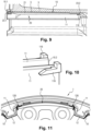
- Each rim 116 is arranged to allow pivoting of the front edge 23.1 of the heat shield 20 between a mounting position in which the heat shield 20 is inclined relative to the rim 3 ( figure 8 ) and a position of use in which the heat shield 20 extends parallel to the rim 3 ( Figure 9 ).
- Each heat shield 20 is provided with an elastically deformable tab 125, presented on the figures 12 and 13 , forming the holding portion and intended to cooperate with a rim 119 (forming the first stop in this embodiment) extending from the free edge 15 of each side wall 11 projecting laterally towards the outside of each bar 10.
- the tab 125 is here formed of a tongue cut from a triangular clip 126 having a base fixed on the surface 21.2 facing the interior surface 4 of the rim 3.
- the tab 125 is arranged to retract elastically in contact with the rim 119 during the pivoting of the heat shield 20 from its mounting position towards its position of use and to oppose the pivoting of the heat shield 20 from the position of use towards the mounting position.
- the tab 125 here has a curved terminal portion 125.1 to rest against a rear face of the rim 119 when the heat shield 20 is in its use position ( Figure 12 ) and an inclined portion 125.2 connecting to the clip 126 which forms a ramp on which a front face of the rim 119 rests and slides during the pivoting of the heat screen 20 from its mounting position to its position of use, causing the elastic deformation of the tab 125 until the rim 119 passes.
- the wheel 1 includes third stops to prevent movement of each heat shield 20 parallel to the wheel pins 5 when the heat shield 20 is in the use position.
- each thermal screen 20 and each strip 10 are provided with corresponding reliefs which are in relative engagement when the thermal screen 20 is in the use position.
- the structure and shape of the strip 10 and/or the structure and shape of the heat shield 20 may be different from those described and/or shown.
- the wheel studs may have a shape different from that described and be in one piece with the rim or attached to it. The bar and the wheel stud can be one and the same part.
- All or part of the stops can be formed by reliefs of the rim 3 including the wheel studs 5.
- the stop 19 is formed by a rim of the bar 10
- the stop could be formed by a projection of the rim 3. It is the same for the stops 16, 116 and 119. It is nevertheless more advantageous to provide these stops on the bars 10 because this limits the contacts between the thermal screens 20 and the rim 3 and therefore heat transfer by conduction.
- the fixing of the thermal screens 20 can be ensured by more than two clips 126, for example four clips arranged at the four corners of each thermal screen 20, the two edges 23 of the thermal screen 20 then being approached to the interior surface 4 of the rim 3 in substantially radial directions of the rim 3.
- each heat shield 20 is here ensured by identical means on both sides of the heat screen 20, it is possible to have different means.
- the heat shield can for example have an edge 22 received in a groove formed along the bar 10 on the right and an edge 22 provided with a clip 126 to cooperate with stops 119 arranged on the bar 10 on the left.
- the fixing means of the two embodiments can for example also be mixed for the same rim 3.
- the bar 10 defines the groove 50 with part of the rim 3, the groove 50 could be formed entirely by the bar 10 by grooving each of the side walls 11.
- Each heat shield 20 can be provided with one or more elastically deformable pads 24 bearing on the rim 3, or be devoid of them.
- the radial positioning means of the heat shields 20 will be positioned so that they are spaced from the lower surface of the rim 3 in order to limit heat transfer by conduction.
- a third stop can be associated, in addition, with homologous reliefs to oppose a movement of each heat shield 20 parallel to the bars 10.
- the rim 3 can be in one or more parts.
Landscapes
- Engineering & Computer Science (AREA)
- Mechanical Engineering (AREA)
- General Engineering & Computer Science (AREA)
- Aviation & Aerospace Engineering (AREA)
- Braking Arrangements (AREA)
Applications Claiming Priority (1)
| Application Number | Priority Date | Filing Date | Title |
|---|---|---|---|
| FR1902060A FR3093321B1 (fr) | 2019-02-28 | 2019-02-28 | Roue d’aéronef pourvue d’écrans thermiques |
Publications (2)
| Publication Number | Publication Date |
|---|---|
| EP3702275A1 EP3702275A1 (fr) | 2020-09-02 |
| EP3702275B1 true EP3702275B1 (fr) | 2024-02-14 |
Family
ID=67810679
Family Applications (1)
| Application Number | Title | Priority Date | Filing Date |
|---|---|---|---|
| EP20159649.1A Active EP3702275B1 (fr) | 2019-02-28 | 2020-02-26 | Roue d'aéronef pourvue d'écrans thermiques |
Country Status (4)
| Country | Link |
|---|---|
| US (1) | US11668363B2 (zh) |
| EP (1) | EP3702275B1 (zh) |
| CN (1) | CN111619793B (zh) |
| FR (1) | FR3093321B1 (zh) |
Families Citing this family (2)
| Publication number | Priority date | Publication date | Assignee | Title |
|---|---|---|---|---|
| FR3117999B1 (fr) | 2020-12-21 | 2022-11-11 | Safran Landing Systems | Dispositif de freinage d’une roue d’aéronef ; roue, train d’atterrissage et aéronef équipés d’un tel dispositif. |
| WO2022235849A1 (en) * | 2021-05-04 | 2022-11-10 | Meggitt Aircraft Braking Systems Corporation | Reinforced torque tubes |
Family Cites Families (15)
| Publication number | Priority date | Publication date | Assignee | Title |
|---|---|---|---|---|
| US3051528A (en) * | 1960-08-15 | 1962-08-28 | Bendix Corp | Segmented heat shield for wheels |
| US4017123A (en) * | 1976-04-02 | 1977-04-12 | The Bendix Corporation | Dual layer heat shield for wheels |
| US4856619A (en) * | 1988-06-06 | 1989-08-15 | Loral Corporation | Aircraft wheel drive key and heatshield assembly |
| EP1516754B1 (en) * | 2001-10-10 | 2007-02-21 | Goodrich Corporation | Heat shield assembly for an aircraft wheel and brake assembly |
| DE60202421T2 (de) * | 2001-10-10 | 2006-01-05 | Goodrich Corp. | Bremsanordnung mit einem Hitzeschild in einem Flugzeugreifen |
| WO2008097386A2 (en) * | 2006-10-23 | 2008-08-14 | Goodrich Corporation | Segmented heat shield assembly |
| FR3022216B1 (fr) | 2014-06-13 | 2018-01-26 | Safran Landing Systems | Roue d'aeronef equipee de moyens de son entrainement en rotation par un actionneur d'entrainement. |
| US9718317B2 (en) * | 2015-10-15 | 2017-08-01 | Goodrich Corporation | Short trapezoidal wheel gasket |
| US9908375B2 (en) * | 2015-10-20 | 2018-03-06 | Goodrich Corporation | Ventilated key-slot full circle heat shield |
| US20170291696A1 (en) * | 2016-04-08 | 2017-10-12 | Goodrich Corporation | Heat-insulated wheel |
| FR3055379B1 (fr) * | 2016-08-24 | 2018-08-10 | Safran Landing Systems | Roue d'aeronef a boitier a roulements separable |
| FR3059270B1 (fr) * | 2016-11-30 | 2019-05-10 | Safran Landing Systems | Roue d'aeronef a talon amovible |
| CN206579836U (zh) * | 2017-02-17 | 2017-10-24 | 西安航空制动科技有限公司 | 一种单片式航空刹车机轮隔热屏 |
| CN107878737A (zh) * | 2017-12-01 | 2018-04-06 | 北京北摩高科摩擦材料股份有限公司 | 一种飞机刹车机轮 |
| US11346418B2 (en) * | 2019-03-19 | 2022-05-31 | Goodrich Corporation | Covered retainer for segmented annular heat shield |
-
2019
- 2019-02-28 FR FR1902060A patent/FR3093321B1/fr active Active
-
2020
- 2020-02-26 CN CN202010119487.0A patent/CN111619793B/zh active Active
- 2020-02-26 EP EP20159649.1A patent/EP3702275B1/fr active Active
- 2020-02-27 US US16/802,911 patent/US11668363B2/en active Active
Also Published As
| Publication number | Publication date |
|---|---|
| CN111619793A (zh) | 2020-09-04 |
| US20200278005A1 (en) | 2020-09-03 |
| CN111619793B (zh) | 2023-12-26 |
| US11668363B2 (en) | 2023-06-06 |
| FR3093321A1 (fr) | 2020-09-04 |
| FR3093321B1 (fr) | 2021-06-18 |
| EP3702275A1 (fr) | 2020-09-02 |
Similar Documents
| Publication | Publication Date | Title |
|---|---|---|
| EP1439282B1 (fr) | Dispositif pour retenir un flasque annulaire contre une face radiale d'un disque | |
| EP0488874B1 (fr) | Rotor de soufflante avec aubes sans plates-formes et sabots reconstituant le profil de veine | |
| EP3702275B1 (fr) | Roue d'aéronef pourvue d'écrans thermiques | |
| EP2839181A1 (fr) | Dispositif d'amortissement pendulaire, en particulier pour une transmission de véhicule automobile | |
| CA2634942A1 (fr) | Perfectionnement a une cale intercalee entre un pied d'aube et le fond de l'alveole du disque dans laquelle il est monte | |
| CA2640003A1 (fr) | Clinquant pour aube de turbomachine | |
| EP2932051A1 (fr) | Panneaux acoustiques amovibles pour carter de turboreacteur | |
| FR2577291A1 (fr) | Butee d'embrayage autocentreuse, notamment pour vehicule automobile, a assemblage compact simplifie | |
| FR2774221A1 (fr) | Boitier a encastrer dans une quelconque paroi, notamment pour appareil electrique | |
| EP0080949B1 (fr) | Frein à disque et patin pour un tel frein | |
| EP2816251B1 (fr) | Frein pour roue d'aéronef, en particulier pour un hélicoptère. | |
| WO2018046813A1 (fr) | Platine support avec filtrage de vibrations d'un ventilateur, échangeur de chaleur, condenseur sur un élément structurel du corps d'un appareil ou véhicule a moteur et procédé de fabrication | |
| FR2732425A1 (fr) | Dispositif amortisseur de torsion a sieges basculants de structure composite pour les ressorts, notamment pour vehicule automobile | |
| EP0196966A1 (fr) | Butée de débrayage, notamment pour véhicule automobile | |
| EP0031338B1 (fr) | Butee de debrayage | |
| FR3073020B1 (fr) | Ecrou autofixant et vehicule automobile comportant un tel ecrou | |
| FR2717543A1 (fr) | Fixation de segments de ressort de garniture sur le disque d'entraînement d'un disque d'embrayage. | |
| EP0677152A1 (fr) | Module d'embrayage a vis de fixation integrees, notamment pour vehicules automobiles | |
| FR3069973A1 (fr) | Rotor de machine electrique tournante muni d'un flasque ayant une fonction de maintien d'aimants permanents | |
| FR3062702A1 (fr) | Dispositif pour l'accouplement de deux tubes avec pre-montage | |
| EP0200633A1 (fr) | Amortisseur de torsion, notamment friction d'embrayage pour véhicule automobile | |
| WO1990004902A1 (fr) | Façade de poste de television | |
| FR2763624A1 (fr) | Verrou de vehicule automobile comportant une barrette perfectionnee de retenue des paillettes | |
| FR2901304A1 (fr) | Volet roulant ou similaire | |
| EP3795877B1 (fr) | Collier de serrage |
Legal Events
| Date | Code | Title | Description |
|---|---|---|---|
| PUAI | Public reference made under article 153(3) epc to a published international application that has entered the european phase |
Free format text: ORIGINAL CODE: 0009012 |
|
| STAA | Information on the status of an ep patent application or granted ep patent |
Free format text: STATUS: THE APPLICATION HAS BEEN PUBLISHED |
|
| AK | Designated contracting states |
Kind code of ref document: A1 Designated state(s): AL AT BE BG CH CY CZ DE DK EE ES FI FR GB GR HR HU IE IS IT LI LT LU LV MC MK MT NL NO PL PT RO RS SE SI SK SM TR |
|
| AX | Request for extension of the european patent |
Extension state: BA ME |
|
| STAA | Information on the status of an ep patent application or granted ep patent |
Free format text: STATUS: REQUEST FOR EXAMINATION WAS MADE |
|
| 17P | Request for examination filed |
Effective date: 20210302 |
|
| RBV | Designated contracting states (corrected) |
Designated state(s): AL AT BE BG CH CY CZ DE DK EE ES FI FR GB GR HR HU IE IS IT LI LT LU LV MC MK MT NL NO PL PT RO RS SE SI SK SM TR |
|
| STAA | Information on the status of an ep patent application or granted ep patent |
Free format text: STATUS: EXAMINATION IS IN PROGRESS |
|
| 17Q | First examination report despatched |
Effective date: 20220408 |
|
| GRAP | Despatch of communication of intention to grant a patent |
Free format text: ORIGINAL CODE: EPIDOSNIGR1 |
|
| STAA | Information on the status of an ep patent application or granted ep patent |
Free format text: STATUS: GRANT OF PATENT IS INTENDED |
|
| RIC1 | Information provided on ipc code assigned before grant |
Ipc: B64C 25/36 20060101ALN20230712BHEP Ipc: B64C 25/42 20060101AFI20230712BHEP |
|
| RIC1 | Information provided on ipc code assigned before grant |
Ipc: B64C 25/36 20060101ALN20230719BHEP Ipc: B64C 25/42 20060101AFI20230719BHEP |
|
| INTG | Intention to grant announced |
Effective date: 20230802 |
|
| GRAS | Grant fee paid |
Free format text: ORIGINAL CODE: EPIDOSNIGR3 |
|
| GRAA | (expected) grant |
Free format text: ORIGINAL CODE: 0009210 |
|
| STAA | Information on the status of an ep patent application or granted ep patent |
Free format text: STATUS: THE PATENT HAS BEEN GRANTED |
|
| AK | Designated contracting states |
Kind code of ref document: B1 Designated state(s): AL AT BE BG CH CY CZ DE DK EE ES FI FR GB GR HR HU IE IS IT LI LT LU LV MC MK MT NL NO PL PT RO RS SE SI SK SM TR |
|
| REG | Reference to a national code |
Ref country code: GB Ref legal event code: FG4D Free format text: NOT ENGLISH |
|
| REG | Reference to a national code |
Ref country code: CH Ref legal event code: EP |
|
| REG | Reference to a national code |
Ref country code: DE Ref legal event code: R096 Ref document number: 602020025509 Country of ref document: DE |
|
| REG | Reference to a national code |
Ref country code: IE Ref legal event code: FG4D Free format text: LANGUAGE OF EP DOCUMENT: FRENCH |
|
| PGFP | Annual fee paid to national office [announced via postgrant information from national office to epo] |
Ref country code: DE Payment date: 20240229 Year of fee payment: 5 Ref country code: GB Payment date: 20240320 Year of fee payment: 5 |
|
| PGFP | Annual fee paid to national office [announced via postgrant information from national office to epo] |
Ref country code: FR Payment date: 20240320 Year of fee payment: 5 |
|
| REG | Reference to a national code |
Ref country code: LT Ref legal event code: MG9D |
|
| REG | Reference to a national code |
Ref country code: NL Ref legal event code: MP Effective date: 20240214 |
|
| PG25 | Lapsed in a contracting state [announced via postgrant information from national office to epo] |
Ref country code: IS Free format text: LAPSE BECAUSE OF FAILURE TO SUBMIT A TRANSLATION OF THE DESCRIPTION OR TO PAY THE FEE WITHIN THE PRESCRIBED TIME-LIMIT Effective date: 20240614 |
|
| PG25 | Lapsed in a contracting state [announced via postgrant information from national office to epo] |
Ref country code: LT Free format text: LAPSE BECAUSE OF FAILURE TO SUBMIT A TRANSLATION OF THE DESCRIPTION OR TO PAY THE FEE WITHIN THE PRESCRIBED TIME-LIMIT Effective date: 20240214 |
|
| PG25 | Lapsed in a contracting state [announced via postgrant information from national office to epo] |
Ref country code: GR Free format text: LAPSE BECAUSE OF FAILURE TO SUBMIT A TRANSLATION OF THE DESCRIPTION OR TO PAY THE FEE WITHIN THE PRESCRIBED TIME-LIMIT Effective date: 20240515 |
|
| REG | Reference to a national code |
Ref country code: AT Ref legal event code: MK05 Ref document number: 1656853 Country of ref document: AT Kind code of ref document: T Effective date: 20240214 |
|
| PG25 | Lapsed in a contracting state [announced via postgrant information from national office to epo] |
Ref country code: HR Free format text: LAPSE BECAUSE OF FAILURE TO SUBMIT A TRANSLATION OF THE DESCRIPTION OR TO PAY THE FEE WITHIN THE PRESCRIBED TIME-LIMIT Effective date: 20240214 Ref country code: RS Free format text: LAPSE BECAUSE OF FAILURE TO SUBMIT A TRANSLATION OF THE DESCRIPTION OR TO PAY THE FEE WITHIN THE PRESCRIBED TIME-LIMIT Effective date: 20240514 Ref country code: NL Free format text: LAPSE BECAUSE OF FAILURE TO SUBMIT A TRANSLATION OF THE DESCRIPTION OR TO PAY THE FEE WITHIN THE PRESCRIBED TIME-LIMIT Effective date: 20240214 |
|
| PG25 | Lapsed in a contracting state [announced via postgrant information from national office to epo] |
Ref country code: ES Free format text: LAPSE BECAUSE OF FAILURE TO SUBMIT A TRANSLATION OF THE DESCRIPTION OR TO PAY THE FEE WITHIN THE PRESCRIBED TIME-LIMIT Effective date: 20240214 |
|
| PG25 | Lapsed in a contracting state [announced via postgrant information from national office to epo] |
Ref country code: AT Free format text: LAPSE BECAUSE OF FAILURE TO SUBMIT A TRANSLATION OF THE DESCRIPTION OR TO PAY THE FEE WITHIN THE PRESCRIBED TIME-LIMIT Effective date: 20240214 |
|
| PG25 | Lapsed in a contracting state [announced via postgrant information from national office to epo] |
Ref country code: RS Free format text: LAPSE BECAUSE OF FAILURE TO SUBMIT A TRANSLATION OF THE DESCRIPTION OR TO PAY THE FEE WITHIN THE PRESCRIBED TIME-LIMIT Effective date: 20240514 Ref country code: NO Free format text: LAPSE BECAUSE OF FAILURE TO SUBMIT A TRANSLATION OF THE DESCRIPTION OR TO PAY THE FEE WITHIN THE PRESCRIBED TIME-LIMIT Effective date: 20240514 Ref country code: NL Free format text: LAPSE BECAUSE OF FAILURE TO SUBMIT A TRANSLATION OF THE DESCRIPTION OR TO PAY THE FEE WITHIN THE PRESCRIBED TIME-LIMIT Effective date: 20240214 Ref country code: LT Free format text: LAPSE BECAUSE OF FAILURE TO SUBMIT A TRANSLATION OF THE DESCRIPTION OR TO PAY THE FEE WITHIN THE PRESCRIBED TIME-LIMIT Effective date: 20240214 Ref country code: IS Free format text: LAPSE BECAUSE OF FAILURE TO SUBMIT A TRANSLATION OF THE DESCRIPTION OR TO PAY THE FEE WITHIN THE PRESCRIBED TIME-LIMIT Effective date: 20240614 Ref country code: HR Free format text: LAPSE BECAUSE OF FAILURE TO SUBMIT A TRANSLATION OF THE DESCRIPTION OR TO PAY THE FEE WITHIN THE PRESCRIBED TIME-LIMIT Effective date: 20240214 Ref country code: GR Free format text: LAPSE BECAUSE OF FAILURE TO SUBMIT A TRANSLATION OF THE DESCRIPTION OR TO PAY THE FEE WITHIN THE PRESCRIBED TIME-LIMIT Effective date: 20240515 Ref country code: FI Free format text: LAPSE BECAUSE OF FAILURE TO SUBMIT A TRANSLATION OF THE DESCRIPTION OR TO PAY THE FEE WITHIN THE PRESCRIBED TIME-LIMIT Effective date: 20240214 Ref country code: ES Free format text: LAPSE BECAUSE OF FAILURE TO SUBMIT A TRANSLATION OF THE DESCRIPTION OR TO PAY THE FEE WITHIN THE PRESCRIBED TIME-LIMIT Effective date: 20240214 Ref country code: BG Free format text: LAPSE BECAUSE OF FAILURE TO SUBMIT A TRANSLATION OF THE DESCRIPTION OR TO PAY THE FEE WITHIN THE PRESCRIBED TIME-LIMIT Effective date: 20240214 Ref country code: AT Free format text: LAPSE BECAUSE OF FAILURE TO SUBMIT A TRANSLATION OF THE DESCRIPTION OR TO PAY THE FEE WITHIN THE PRESCRIBED TIME-LIMIT Effective date: 20240214 |
|
| PG25 | Lapsed in a contracting state [announced via postgrant information from national office to epo] |
Ref country code: PT Free format text: LAPSE BECAUSE OF FAILURE TO SUBMIT A TRANSLATION OF THE DESCRIPTION OR TO PAY THE FEE WITHIN THE PRESCRIBED TIME-LIMIT Effective date: 20240614 Ref country code: PL Free format text: LAPSE BECAUSE OF FAILURE TO SUBMIT A TRANSLATION OF THE DESCRIPTION OR TO PAY THE FEE WITHIN THE PRESCRIBED TIME-LIMIT Effective date: 20240214 |
|
| PG25 | Lapsed in a contracting state [announced via postgrant information from national office to epo] |
Ref country code: SE Free format text: LAPSE BECAUSE OF FAILURE TO SUBMIT A TRANSLATION OF THE DESCRIPTION OR TO PAY THE FEE WITHIN THE PRESCRIBED TIME-LIMIT Effective date: 20240214 Ref country code: PT Free format text: LAPSE BECAUSE OF FAILURE TO SUBMIT A TRANSLATION OF THE DESCRIPTION OR TO PAY THE FEE WITHIN THE PRESCRIBED TIME-LIMIT Effective date: 20240614 Ref country code: PL Free format text: LAPSE BECAUSE OF FAILURE TO SUBMIT A TRANSLATION OF THE DESCRIPTION OR TO PAY THE FEE WITHIN THE PRESCRIBED TIME-LIMIT Effective date: 20240214 Ref country code: LV Free format text: LAPSE BECAUSE OF FAILURE TO SUBMIT A TRANSLATION OF THE DESCRIPTION OR TO PAY THE FEE WITHIN THE PRESCRIBED TIME-LIMIT Effective date: 20240214 |