EP3702274B1 - Drehflügler und verfahren zur steuerung des drehflüglers - Google Patents
Drehflügler und verfahren zur steuerung des drehflüglers Download PDFInfo
- Publication number
- EP3702274B1 EP3702274B1 EP19219919.8A EP19219919A EP3702274B1 EP 3702274 B1 EP3702274 B1 EP 3702274B1 EP 19219919 A EP19219919 A EP 19219919A EP 3702274 B1 EP3702274 B1 EP 3702274B1
- Authority
- EP
- European Patent Office
- Prior art keywords
- rotorcraft
- load
- rotors
- rods
- values
- Prior art date
- Legal status (The legal status is an assumption and is not a legal conclusion. Google has not performed a legal analysis and makes no representation as to the accuracy of the status listed.)
- Active
Links
Images


Classifications
-
- G—PHYSICS
- G05—CONTROLLING; REGULATING
- G05D—SYSTEMS FOR CONTROLLING OR REGULATING NON-ELECTRIC VARIABLES
- G05D1/00—Control of position, course, altitude or attitude of land, water, air or space vehicles, e.g. using automatic pilots
- G05D1/08—Control of attitude, i.e. control of roll, pitch, or yaw
- G05D1/0808—Control of attitude, i.e. control of roll, pitch, or yaw specially adapted for aircraft
- G05D1/0816—Control of attitude, i.e. control of roll, pitch, or yaw specially adapted for aircraft to ensure stability
-
- B—PERFORMING OPERATIONS; TRANSPORTING
- B64—AIRCRAFT; AVIATION; COSMONAUTICS
- B64C—AEROPLANES; HELICOPTERS
- B64C25/00—Alighting gear
- B64C25/32—Alighting gear characterised by elements which contact the ground or similar surface
-
- B—PERFORMING OPERATIONS; TRANSPORTING
- B64—AIRCRAFT; AVIATION; COSMONAUTICS
- B64C—AEROPLANES; HELICOPTERS
- B64C27/00—Rotorcraft; Rotors peculiar thereto
- B64C27/32—Rotors
-
- B—PERFORMING OPERATIONS; TRANSPORTING
- B64—AIRCRAFT; AVIATION; COSMONAUTICS
- B64U—UNMANNED AERIAL VEHICLES [UAV]; EQUIPMENT THEREFOR
- B64U20/00—Constructional aspects of UAVs
- B64U20/60—UAVs characterised by the material
- B64U20/65—Composite materials
-
- B—PERFORMING OPERATIONS; TRANSPORTING
- B64—AIRCRAFT; AVIATION; COSMONAUTICS
- B64U—UNMANNED AERIAL VEHICLES [UAV]; EQUIPMENT THEREFOR
- B64U30/00—Means for producing lift; Empennages; Arrangements thereof
- B64U30/20—Rotors; Rotor supports
- B64U30/29—Constructional aspects of rotors or rotor supports; Arrangements thereof
- B64U30/296—Rotors with variable spatial positions relative to the UAV body
- B64U30/297—Tilting rotors
-
- B—PERFORMING OPERATIONS; TRANSPORTING
- B64—AIRCRAFT; AVIATION; COSMONAUTICS
- B64U—UNMANNED AERIAL VEHICLES [UAV]; EQUIPMENT THEREFOR
- B64U60/00—Undercarriages
- B64U60/10—Undercarriages specially adapted for use on water
-
- B—PERFORMING OPERATIONS; TRANSPORTING
- B64—AIRCRAFT; AVIATION; COSMONAUTICS
- B64U—UNMANNED AERIAL VEHICLES [UAV]; EQUIPMENT THEREFOR
- B64U60/00—Undercarriages
- B64U60/20—Undercarriages specially adapted for uneven terrain
-
- B—PERFORMING OPERATIONS; TRANSPORTING
- B64—AIRCRAFT; AVIATION; COSMONAUTICS
- B64U—UNMANNED AERIAL VEHICLES [UAV]; EQUIPMENT THEREFOR
- B64U60/00—Undercarriages
- B64U60/40—Undercarriages foldable or retractable
-
- B—PERFORMING OPERATIONS; TRANSPORTING
- B64—AIRCRAFT; AVIATION; COSMONAUTICS
- B64U—UNMANNED AERIAL VEHICLES [UAV]; EQUIPMENT THEREFOR
- B64U60/00—Undercarriages
- B64U60/50—Undercarriages with landing legs
-
- G—PHYSICS
- G05—CONTROLLING; REGULATING
- G05D—SYSTEMS FOR CONTROLLING OR REGULATING NON-ELECTRIC VARIABLES
- G05D1/00—Control of position, course, altitude or attitude of land, water, air or space vehicles, e.g. using automatic pilots
- G05D1/04—Control of altitude or depth
- G05D1/06—Rate of change of altitude or depth
- G05D1/0607—Rate of change of altitude or depth specially adapted for aircraft
- G05D1/0653—Rate of change of altitude or depth specially adapted for aircraft during a phase of take-off or landing
- G05D1/0661—Rate of change of altitude or depth specially adapted for aircraft during a phase of take-off or landing specially adapted for take-off
- G05D1/0669—Rate of change of altitude or depth specially adapted for aircraft during a phase of take-off or landing specially adapted for take-off specially adapted for vertical take-off
-
- G—PHYSICS
- G05—CONTROLLING; REGULATING
- G05D—SYSTEMS FOR CONTROLLING OR REGULATING NON-ELECTRIC VARIABLES
- G05D1/00—Control of position, course, altitude or attitude of land, water, air or space vehicles, e.g. using automatic pilots
- G05D1/08—Control of attitude, i.e. control of roll, pitch, or yaw
- G05D1/0808—Control of attitude, i.e. control of roll, pitch, or yaw specially adapted for aircraft
- G05D1/0858—Control of attitude, i.e. control of roll, pitch, or yaw specially adapted for aircraft specially adapted for vertical take-off of aircraft
-
- B—PERFORMING OPERATIONS; TRANSPORTING
- B64—AIRCRAFT; AVIATION; COSMONAUTICS
- B64C—AEROPLANES; HELICOPTERS
- B64C25/00—Alighting gear
- B64C25/001—Devices not provided for in the groups B64C25/02 - B64C25/68
- B64C2025/008—Comprising means for modifying their length, e.g. for kneeling, for jumping, or for leveling the aircraft
-
- B—PERFORMING OPERATIONS; TRANSPORTING
- B64—AIRCRAFT; AVIATION; COSMONAUTICS
- B64C—AEROPLANES; HELICOPTERS
- B64C25/00—Alighting gear
- B64C25/32—Alighting gear characterised by elements which contact the ground or similar surface
- B64C2025/325—Alighting gear characterised by elements which contact the ground or similar surface specially adapted for helicopters
-
- B—PERFORMING OPERATIONS; TRANSPORTING
- B64—AIRCRAFT; AVIATION; COSMONAUTICS
- B64U—UNMANNED AERIAL VEHICLES [UAV]; EQUIPMENT THEREFOR
- B64U10/00—Type of UAV
- B64U10/10—Rotorcrafts
-
- B—PERFORMING OPERATIONS; TRANSPORTING
- B64—AIRCRAFT; AVIATION; COSMONAUTICS
- B64U—UNMANNED AERIAL VEHICLES [UAV]; EQUIPMENT THEREFOR
- B64U2201/00—UAVs characterised by their flight controls
-
- G—PHYSICS
- G01—MEASURING; TESTING
- G01L—MEASURING FORCE, STRESS, TORQUE, WORK, MECHANICAL POWER, MECHANICAL EFFICIENCY, OR FLUID PRESSURE
- G01L1/00—Measuring force or stress, in general
- G01L1/20—Measuring force or stress, in general by measuring variations in ohmic resistance of solid materials or of electrically-conductive fluids; by making use of electrokinetic cells, i.e. liquid-containing cells wherein an electrical potential is produced or varied upon the application of stress
- G01L1/22—Measuring force or stress, in general by measuring variations in ohmic resistance of solid materials or of electrically-conductive fluids; by making use of electrokinetic cells, i.e. liquid-containing cells wherein an electrical potential is produced or varied upon the application of stress using resistance strain gauges
Definitions
- Embodiments described herein relate generally to a rotorcraft and a method of controlling a rotorcraft.
- a rotorcraft having a plurality of rotors is known.
- a rotorcraft having not less than three rotors is also called a multicopter.
- attitude control of a rotorcraft mounting rotors is performed by detecting the attitude of the rotorcraft using a gyroscope sensor or the like (for example, refer to Japanese Patent Application Publication JP 2006-051841 A ).
- control command signals for changing thrust are output to rotors after the attitude changed. Therefore, control directions and responses of an attitude are delayed, which causes instability of the attitude at the time of a takeoff of a rotorcraft.
- an attitude of a rotorcraft becomes unstable, the risk of falling increases.
- an object of the present invention is to improve the safety at the time of a takeoff of a rotorcraft having rotors.
- Patent document US 201 6/272308 A1 relates to an unmanned aerial vehicle landing gear assembly that includes adjustable landing gear extension that may be extended or contracted so that the body of the UAV is contained in a horizontal plane when the UAV is landed, even on sloping surfaces.
- a rotorcraft is disclosed as defined in claim 1.
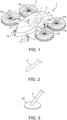
- FIG. 1 is a perspective view showing structure of a rotorcraft according to the first embodiment of the present invention.
- a rotorcraft 1 is composed of a fuselage 2, rotors 3 and rods 4. The rotors 3 and the rods 4 are attached to the fuselage 2.
- the rotorcraft 1 having not less than three rotors 3 is called a multicopter.
- the rotorcraft 1 may be a helicopter which has two rotors 3.
- the rotorcraft 1 may be not only a UAV (unmanned aerial vehicle) on which people do not board but also an OPV (optionally piloted vehicle) on which people board.
- An OPV is an unmanned aerial vehicle which a pilot can also board and drive, i.e., a hybrid aircraft of a manned aircraft and an unmanned aircraft.
- a UAV is also called a drone and typical UAVs include an unmanned multicopter and helicopter.
- the rotors 3 are rotary wings for obtaining lifts at different positions. Each rotor 3 may have a tilt function so that thrust can be obtained by tilting each rotor 3 after a takeoff of the rotorcraft 1.
- a rotor having a purpose other than the purpose of obtaining a lift such as a tail rotor, may be coupled to the fuselage 2 besides the rotors 3 for obtaining lifts.
- the rods 4 are landing gears, which support the fuselage 2, by respectively contacting their tips to a surface on which the rotorcraft 1 lands while the rotorcraft 1 has landed. That is, the rotorcraft 1 does not necessarily have wheels and can land with the tips of the rods 4 as exemplified in FIG. 1 . As a matter of course, wheels may be attached to the tips of the rods 4 for landing with the wheels, regardless of an example shown in FIG. 1 .
- a load sensor 5 is attached to each rod 4. Therefore, a load F1, a load F2, a load F3 and a load F4 applied on the respective rods 4 due to the weight of the rotorcraft 1 except the rods 4 their selves can be detected by the load sensors 5 respectively before a takeoff of the rotorcraft 1.
- Each load sensor 5 can be composed of at least one known sensor, such as a strain gauge or a piezo element. Therefore, an attachment position of the load sensor 5 to each rod 4 is determined to an appropriate position, such as a middle portion or a root portion of each rod 4, according to a shape of each rod 4 and a kind of the load sensor 5.
- FIG. 2 shows the first example of a shape of the rod 4 shown in FIG. 1 .
- the rods 4 each having a linear shape without curvature, can be attached to the fuselage 2 so as to open outward.
- a shape of each rod 4 is linear, design and production of each rod 4 becomes easy.
- the material of each rod 4 is flexible and may be a metal or a composite material as long as the metal has the strength which can support a load of the rotorcraft 1.
- material cost can be reduced.
- weight saving can be attained with keeping high strength.
- a composite material is also called an FRP (fiber reinforced plastic), and a GFRP (glass fiber reinforced plastic) and a CFRP (carbon fiber reinforced plastics) are typical.
- FIG. 3 shows the second example of a shape of the rod 4 shown in FIG. 1 .
- a disk member 4A may be attached to the tip of each rod 4.
- the rotorcraft 1 becomes possible to land on a place of which surface is not rigid, such as a place on the water, marshes, a liquefied land or a place covered with plant.
- FIG. 4 shows the third example of a shape of the rod 4 shown in FIG. 1 .
- the rods 4, each having a curved shape may be attached to the fuselage 2.
- the disk member 4A exemplified in FIG. 3 may also be attached to the tip of each rod 4 having a curved shape.
- each rod 4 having a curved shape is made of an FRP, it becomes easy to give desirable anisotropy to the mechanical characteristic.
- FIG. 5 is a graph explaining an example of a mechanical property given to the rod 4 shown in FIG. 1 .
- the horizontal axis shows displacement of the rod 4 while the vertical axis shows rigidity of the rod 4.
- a nonlinear mechanical characteristic that the rigidity of the rod 4 increases more as the displacement amount caused by bending deformation becomes larger can be given to the rod 4.
- the bending amount of the rod 4 can be made large immediately after landing of the rotorcraft 1 while the bending amount of the rod 4 can be made small gradually. Thereby, the shock at the time of landing of the rotorcraft 1 can be softened.
- Such a mechanical property can also be given to the rod 4 having a linear shape exemplified in FIG. 2 to a certain extent.
- each rod 4 when the rods 4 are attached to the fuselage 2 so that the length directions may not become parallel to the landing direction, each rod 4 can be bent in a case where the load F1, the load F2, the load F3 and the load F4 are applied on the rods 4 respectively. Thereby, the load F1, the load F2, the load F3 and the load F4 can be detected by measuring bending amounts of the rods 4 with strain gauges.
- each load sensor 5 can be composed of strain gauges or the like which detect forces and moments in three axis directions orthogonal to each other so that the bending amounts of the respective rods 4 can be measured.
- the load F1, the load F2, the load F3 and the load F4 applied on the rods 4 respectively can be calculated by known load calculations.
- the fuselage 2 or the like of the rotorcraft 1 houses a control device 6 of the rotorcraft 1, a storage 7 for storing information necessary for controlling the rotorcraft 1 and the like, an input device 8 for inputting information necessary for controlling the rotorcraft 1 and the like into the control device 6, the storage 7, or the like, and a display 9 for displaying information necessary for a flight including a taking off and landing of the rotorcraft 1.
- the input device 8 and the display 9 may be placed outside the fuselage 2 or the like so that the rotorcraft 1 can be remotely operated.
- the control device 6, the storage 7 and the input device 8 can be composed of electric circuits.
- the control device 6 can be built by reading a control program of the rotorcraft 1 into electronic circuitry, such as a computer.
- the control device 6 can control targets to be controlled, including the respective rotation numbers and the respective pitch angles of the rotors 3.
- a pitch angle is an attachment angle of blades which composes each rotor 3, and a lift by the rotor 3 can be adjusted by changing the pitch angle of the rotor 3.
- control device 6 has a function to automatically control the rotors 3 based on the load F1, the load F2, the load F3 and the load F4 applied on the rods 4 respectively, detected by the load sensors 5, at the time of a takeoff of the rotorcraft 1 so that the fuselage 2 of the rotorcraft 1 may be stabilized.
- the fuselage 2 of the rotorcraft 1 is stabilized when the load F1, the load F2, the load F3 and the load F4 applied on the rods 4 respectively are the balanced ideal loads.
- the control device 6 has a function to set targeted values of the load F1, the load F2, the load F3 and the load F4, applied on the rods 4 respectively before a takeoff of the rotorcraft 1, to desirable values which can balance the weight, and a function to control the rotation number and the pitch angle of each rotor 3 so that a state where the rotorcraft 1 does not take off while the load F1, the load F2, the load F3 and the load F4 are applied on the rods 4 respectively is made.
- the control device 6 is configured so as to automatically control outputs P1, P2, P3 and P4 of the rotors 3 so that measured values of the load F1, the load F2, the load F3 and the load F4 applied on the rods 4, detected by the load sensors 5 respectively, before the takeoff become targeted values.
- the lifts obtained as the output P1, the output P2, the output P3 and the output P4 of the rotors 3 can be variably controlled by parameterizing the rotation numbers and the pitch angles of the rotors 3. Therefore, the control device 6 can automatically control the output P1, the output P2, the output P3 and the output P4 of the rotors 3 by automatically setting up controlling values of at least one of the rotation numbers and the pitch angles of the rotors 3.
- the control device 6 can perform feedback control which changes at least one of the rotation numbers and the pitch angles of the rotors 3 so that the measured values of the load F1, the load F2, the load F3 and the load F4 applied on the rods 4 may approximate targeted values.
- feedback control which brings the measured values of the load F1, the load F2, the load F3 and the load F4, applied on the rods 4, close to targeted values can be performed by changing at least one of the rotation number and the pitch angle of each rotor 3 by a predetermined constant increase and decrease amount.
- a change amount of at least one of the rotation number and the pitch angle of each rotor 3 can be set to an appropriate amount based on the measured values of the load F1, the load F2, the load F3 and the load F4 applied on the rods 4, a control response speed can be improved.
- information such as tables or functions, directly or indirectly expressing a relation between sets of the measured values of the load F1, the load F2, the load F3 and the load F4 applied on the rods 4 respectively before a takeoff, and sets of control values of at least one of the rotation numbers and the pitch angles of the rotors 3 for bringing the measured values of the load F1, the load F2, the load F3 and the load F4 close to targeted values
- the obtained information such as tables or functions can be stored in the storage 7.
- control device 6 becomes possible to automatically set up control values of at least one of the rotation numbers and the pitch angles of the rotors 3, corresponding to the measured values of the load F1, the load F2, the load F3 and the load F4 applied on the rods 4 respectively, with reference to the information stored in the storage 7.
- FIG. 6 is a graph showing an example of a function for automatically setting up the outputs P1, P2, P3, and P4 of the respective rotors 3 based on the loads F1, F2, F3, and F4 respectively applied on the rods 4 of the rotorcraft 1 shown in FIG. 1 .
- the horizontal axis shows a load F applied on each rod 4 of the rotorcraft 1 while the vertical axis shows an output P from each rotor 3.
- information showing a relation between measured values Fm of a load F applied on a certain rod 4 and targeted values Pt of an output P of the corresponding rotor 3, as exemplified in FIG. 6 can be stored in the storage 7 as a piece of information indirectly showing a relation between the loads F applied on the respective rods 4 before a takeoff and control values of at least one of the rotation numbers and the pitch angles of the rotors 3.
- the output P of each rotor 3 is set to an initial value Pi so that the load F applied to the corresponding rod 4 before a takeoff may be a targeted value Ft
- the measured value Fm of the load F measured by the load sensor 5 does not necessarily coincide with the targeted value Ft due to a disturbance, such as a wind.
- the targeted value Pt of the output P from each rotor 3 which should be re-set in order to bring the measured value Fm of the load F close to the targeted value Ft can be set with reference to the information, such as functions or tables.
- information for obtaining the targeted value Pt of the output P from a certain rotor 3, based on the measured value Fm of the load F applied on the corresponding rod 4, is a linear function.
- At least one value or a combination of measured values Fm of the load F1, the load F2, the load F3 and the load F4 applied on at least one of the rods 4 before a takeoff may be related to at least one value or a combination of targeted values Pt of the output P1, the output P2, the output P3 and the output P4 from at least one of the rotors 3, with at least one function or table.
- the control device 6 can specify a lift balance expressed by a combination of lifts which should be generated by the rotors 3, based on a load balance expressed by a combination of the measured values Fm of the load F1, the load F2, the load F3 and the load F4 applied to the rods 4 and detected by the load sensors 5.
- the control device 6 can automatically set up the control values of at least one of the rotation numbers and the pitch angles of the rotors 3, based on the targeted values Pt of the outputs P1, P2, P3 and P4 of the rotors 3.
- information directly showing a relation between sets of the measured values Fm of the load F1, the load F2, the load F3 and the load F4 applied on the rods 4 respectively before a takeoff and sets of the control values of at least one of the rotation numbers and the pitch angles of the rotors 3 may be prepared as functions or tables, and stored in the storage 7.
- conversion information in which the vertical axis of FIG. 6 is replaced with control values of the rotation number or the pitch angle of the rotor 3 may be previously obtained by examinations, simulations or the like, and stored as reference information in the storage 7.
- the control value of the rotation number or the pitch angle of the rotor 3 can be specified directly by referring to the reference information stored in the storage 7.
- the force acting on each rod 4 by a disturbance may change temporally. Therefore, feedback control which dynamically repeats measurement of the measured values Fm of the load F1, the load F2, the load F3 and the load F4 applied on the rods 4 respectively, and an automatic setting of the control values of the rotation numbers or the pitch angles of the rotors 3, based on the reference information stored in the storage 7 may be performed.
- the output P1, the output P2, the output P3 and the output P4 of the rotors 3 are increased under control by the control device 6 so that a lift necessary for a takeoff of the rotorcraft 1 can be generated. Thereby, the rotorcraft 1 can take off.
- control device 6 can control to stop a takeoff of the rotorcraft 1 in a case where the body of the rotorcraft 1 excessively vibrates by a disturbance, such as a wind.
- the scale of a vibration which generated on the body including the fuselage 2 of the rotorcraft 1 can be detected based on time variations of the load F1, the load F2, the load F3 and the load F4 detected by the load sensors 5.
- the vibration scale can be expressed by desired parameters, such as amplitudes and frequencies of time changes of the load F1, the load F2, the load F3 and the load F4 detected by the load sensors 5. Specifically, it can be determined that the vibration scale is large when temporal variation amounts or variation amounts per unit time of the load F1, the load F2, the load F3 and the load F4 applied on the rods 4 respectively are large.
- control device 6 can be provided with a function to detect parameters showing the vibration scale of the fuselage 2, based on time changes of the measured values Fm of the load F1, the load F2, the load F3 and the load F4 detected by the load sensors 5 and to perform processing in order to stop a takeoff when it was automatically determined that at least one detected parameter was out of an allowable range.
- Examples of processing in order to stop a takeoff of the rotorcraft 1 include control processing which automatically stops the takeoff of the rotorcraft 1 by automatically stop rotations of the rotors 3 under control by the control device 6.
- warning information to stop a takeoff may be indicated on the display 9 so that a pilot in the rotorcraft 1 or a manipulator who remotely controls the rotorcraft 1 can manually stop rotations of the rotors 3.
- Such information processing allows a judgment whether the rotorcraft 1 can take off safely, before a takeoff.
- FIG. 7 is a flow chart showing a flow of control at the time of a takeoff of the rotorcraft 1 shown in FIG. 1 .
- step S1 the control device 6 sets the targeted values Ft of the load F1, the load F2, the load F3 and the load F4 applied on the rods 4 which function as a landing gear of the rotorcraft 1.
- the targeted values Ft of the load F1, the load F2, the load F3 and the load F4 applied on the rods 4 respectively may be set as fixed values in advance, or may be variably set by operation of the input device 8.
- step S2 the values of the output P1, the output P2, the output P3 and the output P4 of the rotors 3, which should be set in order to make the load F1, the load F2, the load F3 and the load F4, applied on the rods 4 respectively, be the targeted values Ft, in a case where a force by a disturbance, such as a wind, does not act on the rotorcraft 1, are set to the initial values Pi by the control device 6.
- step S3 the control device 6 automatically controls the rotation numbers and the pitch angles of the rotors 3 so that the output P 1, the output P2, the output P3 and the output P4 of the rotors 3 may be the initial values Pi. Then, a lift by which the rotorcraft 1 cannot take off is generated by rotating the rotors 3. Consequently, the load F1, the load F2, the load F3 and the load F4 applied on the rods 4 respectively decrease compared with those before starting the rotations of the rotors 3.
- step S4 the measured values Fm of the load F1, the load F2, the load F3 and the load F4 applied on the rods 4 respectively are detected by the load sensors 5.
- the detected measured values Fm of the load F1, the load F2, the load F3 and the load F4 are output from the load sensors 5 to the control device 6.
- step S5 the measured values Fm of the load F1, the load F2, the load F3 and the load F4 applied on the rods 4 respectively are compared with the targeted values Ft respectively in the control device 6. Thereby, respective deviation amounts of the measured values Fm from the targeted values Ft are obtained. For example, the differences or ratios between the targeted values Ft and the measured values Fm can be calculated as the deviation amounts of the measured values Fm respectively.
- the control device 6 automatically determines whether the deviation amounts of the measured values Fm of the load F1, the load F2, the load F3 and the load F4 applied on the rods 4 respectively are each within an allowable range.
- it is automatically determined by threshold processing whether the measured values Fm of the load F1, the load F2, the load F3 and the load F4 applied on the rods 4 respectively are each within an allowable range which is specified by an upper limit value and a lower limit value, such as ⁇ 10 [N], set experientially.
- the measured value Fm of the load F applied on a certain rod 4 exceeds an allowable range and becomes excessive as exemplified in FIG. 6 .
- the control value of the output P of at least one corresponding rotor 3 is corrected to the targeted value Pt, in step S6.
- the targeted value Pt of the output P of the at least one corresponding rotor 3 can be automatically set in the control device 6, based on the reference information expressed as a function or a table as exemplified in FIG. 6 .
- control device 6 refers to the reference information, such as a linear function, stored in the storage 7 and automatically set the targeted values Pt of the output P 1, the output P2, the output P3 and the output P4 of the rotors 3, corresponding to the measured values Fm of the load F 1, the load F2, the load F3 and the load F4 applied on the rods 4 respectively.
- reference information such as a linear function
- step S7 the control device 6 automatically controls the rotation numbers and the pitch angles of the rotors so that the output P 1, the output P2, the output P3 and the output P4 of the rotors 3 may be the targeted values Pt.
- the measured values Fm of the load F 1, the load F2, the load F3 and the load F4 applied on the rods 4 respectively can be brought close to the targeted values Ft. That is, the rotors 3 can be automatically controlled so that the body including the fuselage 2 can be stabilized.
- step S4 After at least one of the rotation number and the pitch angle of at least one rotor 3 has been changed, the measurement of the measured values Fm of the load F1, the load F2, the load F3 and the load F4 in step S4 and the determination in step S5 are performed again.
- step S6 the correction of the targeted value Pt or the targeted values Pt of the output P1, the output P2, the output P3 and/or the output P4 of a rotor 3 or rotors 3 in step S6 and the control of the rotation number and the pitch angle of each rotor 3 in step S7 are repeated until it is determined that all of the deviation amounts from the targeted values Ft, of the measured values Fm of the load F 1, the load F2, the load F3 and the load F4 applied on the rods 4 are each within an allowable range in the determination in step S5.
- the measured values Fm of the load F 1, the load F2, the load F3 and the load F4 applied on the rods 4 can be brought close to the targeted values Ft respectively.
- step S5 takeoff control of the rotorcraft 1 is performed in step S8. That is, the control device 6 increases the output P1, the output P2, the output P3 and the output P4 of the rotors 3.
- the measured values Fm of the load F1, the load F2, the load F3 and the load F4 applied on the rods 4 decrease gradually, and the rotorcraft 1 takes off at the time when each of the measured values Fm of the load F1, the load F2, the load F3 and the load F4 becomes zero.
- the vibration scale of the rotorcraft 1 may be detected based on time changes of the load F1, the load F2, the load F3 and the load F4 detected by the load sensors 5 in advance of the flow shown in FIG. 7 , and a takeoff can be stopped when a vibration has become excessive.
- the load sensors 5 attached to the rods 4 which are landing devices of the rotorcraft 1 measures the measured values Fm of the loads F, and the outputs P of the necessary rotors 3 out of the rotors 3 are corrected so that the rotorcraft 1 takes off after the load F applied to each rod 4 has become the targeted value Ft.
- the instability of the body at the time of a takeoff can be suppressed.
- stability and safety can be improved.
- the attitude of the body of the rotorcraft 1 can be stabilized since the rotorcraft 1 can take off after uniforming the load F1, the load F2, the load F3 and the load F4 applied on the rods 4, composing a landing gear, just before a takeoff of the rotorcraft 1.
- FIG. 8 is a front view showing structure of a rotorcraft according to the second embodiment of the present invention.
- a rotorcraft 1A in the second embodiment shown in FIG. 8 is different from the rotorcraft 1 in the first embodiment in a structure by which the attitude of the body can be horizontal even when the rotorcraft 1A lands on a sloping surface 10.
- Other configurations and actions of the rotorcraft 1A in the second embodiment are not substantially different from those of the rotorcraft 1 in the first embodiment. Therefore, only a schematic front view of the rotorcraft 1A is shown, and the same signs are attached to the same elements or the corresponding elements while explanation thereof is omitted.
- the rotorcraft 1A in the second embodiment includes an angle sensor 11, expansion mechanisms 12 and a rod control device 13 in addition to elements similar to those in the first embodiment.
- the angle sensor 11 detects an inclined angle of the body including the fuselage 2, relative to the horizontal direction.
- the expansion mechanisms 12 expand and contract the rods 4 respectively.
- the rod control device 13 expands and contracts the rods 4 by controlling the expansion mechanisms 12 respectively.
- the angle sensor 11 can be disposed at a desired position as long as a spatial inclined angle of the body can be measured.
- Examples of the expansion mechanism 12 which expands and contracts the rod 4 include known mechanisms, such as a rack and pinion which is a kind of gears, a ball screw and a cylinder mechanism having a piston.
- the rod control device 13 can be composed of electronic circuitry, such as a computer, which has read a program, similarly to the control device 6 of the rotorcraft 1A. Accordingly, the rod control device 13 may be integrated with the control device 6 of the rotorcraft 1A.
- the attitude may become unstable since a lift generated by each rotor 3 is not in the vertical direction. Accordingly, the inclination of the rotorcraft 1A can be detected by the angle sensor 11, and the attitude of the rotorcraft 1A can be horizontal by expanding and contracting the necessary rods 4 by the expansion mechanisms 12 when the rotorcraft 1A is inclined.
- the inclined angle to the horizontal direction of the rotorcraft 1A detected by the angle sensor 11 can be output to the rod control device 13. Then, the rod control device 13 can determine whether the inclined angle of the rotorcraft 1A is within an allowable range, by threshold processing.
- the rod control device 13 can control the expansion mechanisms 12 to expand and contract at least one of the rods 4 so that the inclined angle of the rotorcraft 1A detected by the angle sensor 11 may become within the allowable range.
- FIG. 9 is a front view showing a state where the attitude of the rotorcraft 1A shown in FIG. 8 is horizontal.
- the rods 4 can be expanded and contracted according to an inclined angle of the sloping surface 10.
- the body of the rotorcraft 1A can be made horizontal and a lift obtained by rotation of each rotor 3 can be directed in the vertical direction.
- stabilization control including setting the targeted values Ft of the load F1, the load F2, the load F3 and the load F4 applied to the rods 4 and setting the targeted values Pt of the output P1, the output P2, the output P3 and the output P4 of the rotors 3, similarly to the first embodiment.
- the protruding length of the rod 4 or the length itself of the rod 4 is changed depending on a structure of the rod 4.
- the tip of the rod 4 may be bent and deformed with a different deformation amount even when the load F applied on the rod 4 is constant.
- each load sensor 5 can be configured to detect the load F applied on the rod 4, based on an expansion amount and a deformation amount of the rod 4.
- a stable takeoff can be realized by avoiding generation of a lift in a direction oblique to the vertical direction even when the rotorcraft 1A takes off from the sloping surface 10 oblique to the horizontal direction.
Landscapes
- Engineering & Computer Science (AREA)
- Aviation & Aerospace Engineering (AREA)
- Remote Sensing (AREA)
- Mechanical Engineering (AREA)
- General Physics & Mathematics (AREA)
- Radar, Positioning & Navigation (AREA)
- Physics & Mathematics (AREA)
- Automation & Control Theory (AREA)
- Composite Materials (AREA)
- Materials Engineering (AREA)
- Chemical & Material Sciences (AREA)
- Testing Of Devices, Machine Parts, Or Other Structures Thereof (AREA)
- Toys (AREA)
Claims (10)
- Drehflügler (1), der das Folgende aufweist:- Rotoren (3) zum Erhalten von Auftrieb an verschiedenen Positionen;- einen Rumpf (2), der mit den Rotoren (3) verbunden ist;- mindestens drei Stäbe (4), die den Rumpf (2) tragen;- einen Lastsensor (5), der an dem jeweiligen der mindestens drei Stäbe (4) angebracht ist und dazu konfiguriert ist, Lasten (F1, F2, F3, F4) zu detektieren, die vor einem Abheben des Drehflüglers (1) auf die mindestens drei Stäbe (4) einwirken; und- eine Steuervorrichtung (6), die dazu konfiguriert ist, die Rotoren (3) automatisch so zu steuern, dass Messwerte (Fm) der Lasten (F1, F2, F3, F4), die von dem mindestens einen Lastsensor (5) detektiert worden sind, auf Sollwerte (Ft) der Lasten (F1, F2, F3, F4) gebracht werden, dadurch gekennzeichnet,dass die Steuervorrichtung (6) dazu konfiguriert ist,die Sollwerte (Ft) der Lasten (F1, F2, F3, F4) vor dem Abheben des Drehflüglers (1) vorzugeben,die Drehzahlen und Anstellwinkel der Rotoren (3) automatisch so zu steuern, dass die Leistungen (P1, P2, P3, P4) der Rotoren (3) zu Initialwerten (Pi) werden und dadurch einen Auftrieb erzeugen, durch den der Drehflügler (1) durch Drehen der Rotoren (3) nicht abheben kann,eine Rückkopplungssteuerung durchzuführen, die die Drehzahlen und/oder Anstellwinkel der Rotoren (3) so ändert, dass die Messwerte der Lasten (F1, F2, F3, F4) nahe an die Sollwerte (Ft) der Lasten (F1, F2, F3, F4) gebracht werden, unddie Leistungen (P1, P2, P3, P4) der Rotoren (3) so zu erhöhen, dass der Drehflügler (1) abhebt, wenn alle Abweichungsbeträge der Messwerte (Fm) von den Sollwerten (Ft) jeweils innerhalb eines zulässigen Bereichs liegen.
- Drehflügler (1) nach Anspruch 1,
der ferner das Folgende aufweist:einen Speicher, der dazu konfiguriert ist, Informationen zu speichern, die direkt oder indirekt eine Relation zwischen den Lasten (F1, F2, F3, F4), die auf die mindestens drei Stäbe (4) vor einem Abheben des Drehflüglers (1) einwirken, und Steuerwerten von den Drehzahlen und/oder Anstellwinkeln der Rotoren (3) ausdrücken,wobei die Steuervorrichtung (6) dazu konfiguriert ist, die Steuerwerte für zumindest einen von den Drehzahlen und/oder den Neigungswinkeln unter Bezugnahme auf die Informationen automatisch vorzugeben, die von dem Speicher gespeichert sind. - Drehflügler (1) nach Anspruch 2,wobei Informationen, die eine Relation zwischen den Messwerten der Lasten (F1, F2, F3, F4), die auf die mindestens drei Stäbe (4) vor dem Abheben einwirken, und Sollwerten von Leistungen der Rotoren (3) ausdrücken, in dem Speicher gespeichert werden, wobei die Informationen indirekt die Relation zwischen den Lasten (F1, F2, F3, F4) und den Steuerwerten ausdrücken, undwobei die Steuervorrichtung (6) dazu konfiguriert ist, die Steuerwerte automatisch basierend auf den Zielwerten der Leistungen der Rotoren (3) vorzugeben.
- Drehflügler (1) nach einem der Ansprüche 1 bis 3,
wobei die Steuervorrichtung (6) dazu konfiguriert ist, einen Parameter zu detektieren, der ein Vibrationsausmaß des Rumpfes (2) ausdrückt, basierend auf Änderungen der Lasten (F1, F2, F3, F4), die von den Lastsensoren (5) detektiert worden sind, über die Zeit, und eine Verarbeitung zum Stoppen eines Abhebens des Drehflüglers (1) durchzuführen, wenn die Steuervorrichtung (6) automatisch festgestellt hat, dass der detektierte Parameter außerhalb eines zulässigen Bereichs liegt. - Drehflügler (1A) nach einem der Ansprüche 1 bis 4,
der ferner das Folgende aufweist:- einen Winkelsensor (11), der dazu konfiguriert ist, einen Neigungswinkel des Rumpfes (2) zu einer horizontalen Richtung zu detektieren;- einen Expansionsmechanismus (12), der dazu konfiguriert ist, die mindestens drei Stäbe (4) zu expandieren und zu kontrahieren; und- eine Stabsteuervorrichtung (6), die dazu konfiguriert ist, mindestens einen von den mindestens drei Stäben (4) zu expandieren und zu kontrahieren, indem sie den Expansionsmechanismus (12) steuert, wenn der Neigungswinkel, der von dem Winkelsensor (11) detektiert worden ist, außerhalb eines zulässigen Winkelbereichs liegt, sodass der Neigungswinkel in den zulässigen Winkelbereich gebracht wird. - Drehflügler (1A) nach Anspruch 5,
wobei die Lastsensoren (5) dazu konfiguriert sind, die Lasten (F1, F2, F3, F4) basierend auf Expansions- und Kontraktionsbeträgen der mindestens drei Stäbe (4) und Verformungsbeträgen der mindestens drei Stäbe (4) zu detektieren. - Drehflügler (1, 1A) nach einem der Ansprüche 1 bis 6,
wobei die Längsrichtungen der mindestens drei Stäbe (4) nicht parallel zueinander sind, sodass sich die mindestens drei Stäbe (4) biegen, wenn die Lasten (F1, F2, F3, F4) auf die mindestens drei Stäbe (4) einwirken, und wobei die Lastsensoren (5) dazu konfiguriert sind, die Lasten (F1, F2, F3, F4) zu detektieren, indem sie mit Dehnungsmessgeräten die Biegungsverformungsbeträge der mindestens drei Stäbe (4) messen. - Drehflügler (1, 1A) nach einem der Ansprüche 1 bis 7,
wobei die mindestens drei Stäbe (4) nicht gekrümmt sind, lineare Formen aufweisen und nach außen hin offen sind. - Drehflügler (1, 1A) nach einem der Ansprüche 1 bis 8,
wobei ein Scheibenelement (4A) an einer Spitze von mindestens einem der mindestens drei Stäbe (4) angebracht ist. - Verfahren zum Steuern eines Drehflüglers (1, 1A), der das Folgede aufweist: Rotoren (3) zum Erhalten von Auftrieb an verschiedenen Positionen, einen Rumpf (2), der mit den Rotoren (3) verbunden ist, und mindestens drei Stäbe (4), die den Rumpf (2) tragen,
wobei das Verfahren die folgenden Schritte umfasst:- Detektieren von Lasten (F1, F2, F3, F4), die auf die mindestens drei Stäbe (4) vor einem Abheben des Drehflüglers einwirken; und- automatisches Steuern der Rotoren (3), sodass Messwerte der detektierten Lasten (F1, F2, F3, F4) auf Sollwerte der Lasten (F1, F2, F3, F4) gebracht werden,gekennzeichnet durch:- Vorgeben der Sollwerte (Ft) der Lasten (F1, F2, F3, F4) vor dem Abheben des Drehflüglers (1),- automatisches Steuern der Drehzahlen und Anstellwinkel der Rotoren (3), sodass die Leistungen (P1, P2, P3, P4) der Rotoren (3) zu Initialwerten (Pi) werden und dadurch einen Auftrieb erzeugen, durch den der Drehflügler (1) durch Drehen der Rotoren (3) nicht abheben kann,- Durchführen einer Rückkopplungssteuerung, welche die Drehzahl und/oder die Anstellwinkel der Rotoren so ändert, dass die Messwerte der Lasten nahe an die Sollwerte der Lasten gebracht werden, und- Erhöhen der Leistungen (P1, P2, P3, P4) der Rotoren (3), sodass der Drehflügler (1) abhebt, wenn alle Abweichungsbeträge der Messwerte (Fm) von den Sollwerten (Ft) jeweils innerhalb eines zulässigen Bereichs liegen.
Applications Claiming Priority (1)
| Application Number | Priority Date | Filing Date | Title |
|---|---|---|---|
| JP2019038075A JP7269033B2 (ja) | 2019-03-01 | 2019-03-01 | 回転翼航空機 |
Publications (2)
| Publication Number | Publication Date |
|---|---|
| EP3702274A1 EP3702274A1 (de) | 2020-09-02 |
| EP3702274B1 true EP3702274B1 (de) | 2023-06-07 |
Family
ID=69055708
Family Applications (1)
| Application Number | Title | Priority Date | Filing Date |
|---|---|---|---|
| EP19219919.8A Active EP3702274B1 (de) | 2019-03-01 | 2019-12-27 | Drehflügler und verfahren zur steuerung des drehflüglers |
Country Status (3)
| Country | Link |
|---|---|
| US (1) | US11320840B2 (de) |
| EP (1) | EP3702274B1 (de) |
| JP (1) | JP7269033B2 (de) |
Families Citing this family (11)
| Publication number | Priority date | Publication date | Assignee | Title |
|---|---|---|---|---|
| JP7371586B2 (ja) * | 2020-07-28 | 2023-10-31 | トヨタ自動車株式会社 | 飛行体離陸制御システム |
| JP7638289B2 (ja) * | 2020-09-03 | 2025-03-03 | Thk株式会社 | 飛行ロボット |
| WO2022160175A1 (zh) * | 2021-01-28 | 2022-08-04 | 深圳市大疆创新科技有限公司 | 控制方法和无人飞行器 |
| JP2024533484A (ja) * | 2021-09-13 | 2024-09-12 | オーソドローン・ゲゼルシャフト・ミット・ベシュレンクテル・ハフツング | 航空機 |
| CN114194382B (zh) * | 2022-01-21 | 2024-02-27 | 东营航空产业技术研究院 | 一种无人机自动配平装置及方法 |
| JP7745497B2 (ja) * | 2022-03-30 | 2025-09-29 | 本田技研工業株式会社 | 飛行体の着陸脚 |
| CN114906318A (zh) * | 2022-06-10 | 2022-08-16 | 清华大学 | 旋翼无人机被动式自适应起落架和旋翼无人机 |
| JP2024068590A (ja) | 2022-11-08 | 2024-05-20 | 株式会社Subaru | 回転翼航空機 |
| CN116166036B (zh) * | 2022-12-12 | 2025-10-21 | 浙江华飞智能科技有限公司 | 一种飞行器降落方法、装置和飞行器 |
| JP2024092568A (ja) * | 2022-12-26 | 2024-07-08 | Thk株式会社 | 移動ロボット |
| JP2024092496A (ja) * | 2022-12-26 | 2024-07-08 | Thk株式会社 | 移動ロボット |
Family Cites Families (24)
| Publication number | Priority date | Publication date | Assignee | Title |
|---|---|---|---|---|
| WO1988008391A1 (en) | 1987-04-29 | 1988-11-03 | Bell Helicopter Textron Inc. | Landing gear load transducer |
| JP2739957B2 (ja) | 1988-06-08 | 1998-04-15 | 松下電器産業株式会社 | 電動送風機 |
| JPH11310199A (ja) * | 1998-04-28 | 1999-11-09 | Hiroyoshi Mori | ヘリコプタ |
| JP2006051841A (ja) | 2004-08-09 | 2006-02-23 | Ishikawajima Harima Heavy Ind Co Ltd | 小型飛行装置 |
| US9354635B2 (en) | 2012-06-05 | 2016-05-31 | Textron Innovations Inc. | Takeoff/landing touchdown protection management system |
| EP2672238A1 (de) * | 2012-06-06 | 2013-12-11 | Eurocopter Deutschland GmbH | System zur Detektion der Grundbelastung und Verfahren zum Betrieb des besagten Systems |
| US9540121B2 (en) * | 2015-02-25 | 2017-01-10 | Cisco Technology, Inc. | Pre-flight self test for unmanned aerial vehicles (UAVs) |
| US9592908B2 (en) | 2015-03-18 | 2017-03-14 | Amazon Technologies, Inc. | Adjustable landing gear assembly for unmanned aerial vehicles |
| FR3035978A1 (fr) * | 2015-05-04 | 2016-11-11 | Airbus Helicopters | Systeme de commande de giravion, giravion associe et methode de commande correspondante |
| JP6662121B2 (ja) | 2016-03-11 | 2020-03-11 | 株式会社富士通アドバンストエンジニアリング | 飛行体の重心位置表示方法および飛行体の重心位置表示システム |
| US9994307B2 (en) * | 2016-03-25 | 2018-06-12 | The United States Of America As Represented By Secretary Of The Navy | Vertical take-off-and-landing unmanned aerial vehicle system capable of landing on uneven or sloped terrain |
| KR101800662B1 (ko) * | 2016-05-09 | 2017-11-23 | 유콘시스템 주식회사 | 자체적으로 무게 중심을 조정하는 드론 |
| KR20170138797A (ko) | 2016-06-08 | 2017-12-18 | 엘지전자 주식회사 | 드론 |
| US10514690B1 (en) * | 2016-11-15 | 2019-12-24 | Amazon Technologies, Inc. | Cooperative autonomous aerial and ground vehicles for item delivery |
| CA3052304A1 (en) * | 2017-03-04 | 2018-09-13 | Electrafly, LLC | Multi-rotor aircraft and related systems and methods |
| CN107069538A (zh) | 2017-03-15 | 2017-08-18 | 王忠阳 | 基于多旋翼无人机技术的导线走行式线路巡检装置 |
| DE102017118335A1 (de) * | 2017-08-11 | 2019-02-14 | Airbus Defence and Space GmbH | Schwebeflugfähiges Luftfahrzeug |
| US10281913B2 (en) * | 2017-08-14 | 2019-05-07 | The Boeing Company | Methods and systems for intelligent predictive aircraft takeoff rejection decision making |
| WO2019037100A1 (en) * | 2017-08-25 | 2019-02-28 | SZ DJI Technology Co., Ltd. | ALTITUDE ESTIMATION FOR AERIAL VEHICLES |
| CN107972862B (zh) * | 2017-11-21 | 2020-11-17 | 歌尔科技有限公司 | 基于无人机的载重控制方法、设备及无人机 |
| JP6448071B2 (ja) | 2018-02-23 | 2019-01-09 | 株式会社佐竹技研 | ドローン |
| GB2576787B (en) * | 2018-09-03 | 2022-05-11 | Ge Aviat Systems Ltd | Measuring weight and balance and optimizing center of gravity |
| US11352131B2 (en) * | 2018-10-18 | 2022-06-07 | Aurora Flight Sciences Corporation | Multi-point contact, flexed landing gear |
| US12134461B2 (en) * | 2018-12-18 | 2024-11-05 | The Boeing Company | Apparatus for controlling multi-rotor vehicle vibrations and related methods |
-
2019
- 2019-03-01 JP JP2019038075A patent/JP7269033B2/ja active Active
- 2019-12-17 US US16/716,996 patent/US11320840B2/en active Active
- 2019-12-27 EP EP19219919.8A patent/EP3702274B1/de active Active
Also Published As
| Publication number | Publication date |
|---|---|
| US11320840B2 (en) | 2022-05-03 |
| US20200278699A1 (en) | 2020-09-03 |
| JP2020138713A (ja) | 2020-09-03 |
| EP3702274A1 (de) | 2020-09-02 |
| JP7269033B2 (ja) | 2023-05-08 |
Similar Documents
| Publication | Publication Date | Title |
|---|---|---|
| US11320840B2 (en) | Rotorcraft and method of controlling rotorcraft | |
| EP3453609B1 (de) | Aktiver verwindungsmechanismus und steuerungssystem | |
| US8056865B2 (en) | Mechanism for changing the shape of a control surface | |
| US10279891B2 (en) | Software controlled stiffening of flexible aircraft | |
| CN105468009B (zh) | 应用于微小型飞行器的多动力融合飞控系统以及方法 | |
| Ma et al. | Design and fabrication of an insect-scale flying robot for control autonomy | |
| JP4984591B2 (ja) | 自動姿勢制御装置、自動姿勢制御方法及び自動姿勢制御プログラム | |
| CN113039122B (zh) | 用于控制航空器的方法和航空器(变型) | |
| Hrishikeshavan et al. | Design, performance and testing of a quad rotor biplane micro air vehicle for multi role missions | |
| CN105083536A (zh) | 用于优化水平尾翼载荷的系统和方法 | |
| EP3476722B1 (de) | Kipprotorklappenwirbelstabilitätsregelung mit nabenscherrückmeldung für hochgeschwindigkeitsflugzeug | |
| CN109715494B (zh) | 驱动飞机空气动力学操纵面的致动器的开环和闭环控制 | |
| CN115285343A (zh) | 一种高抗风性系留无人机 | |
| CN110015443A (zh) | 具有主动支撑件的飞行器 | |
| WO2021148338A1 (en) | Load control for an aircraft wing | |
| US20240391597A1 (en) | Damping unit as a secondary load path for a movable element with actuator | |
| US20240010326A1 (en) | Vehicle based optimization system and method therefor | |
| Loxton et al. | An investigation of fixed and rotary wing MAV flight in replicated atmospheric turbulence | |
| Higashino et al. | Automatic microgravity flight system and flight testing using a small unmanned aerial vehicle | |
| RU2774495C1 (ru) | Способ пилотирования гибридного вертолета, имеющего планер, удерживаемый с постоянным углом атаки посредством регулирования положения по меньшей мере одной подвижной плоскости оперения | |
| Rohde-Brandenburger | Inflight Measurements of Rudder Deflections in Circling Flight | |
| Lonkar et al. | Development of a Fixed-Wing VTOL UAV for Cargo Delivery Using Additive Manufacturing | |
| CN117075622A (zh) | 一种纵列双旋翼飞行器及其飞行控制方法 | |
| KR20260035830A (ko) | 항공기 비행 제어를 위한 시스템 및 방법 | |
| HK40055586B (zh) | 用於控制航空器的方法和航空器(变型) |
Legal Events
| Date | Code | Title | Description |
|---|---|---|---|
| PUAI | Public reference made under article 153(3) epc to a published international application that has entered the european phase |
Free format text: ORIGINAL CODE: 0009012 |
|
| STAA | Information on the status of an ep patent application or granted ep patent |
Free format text: STATUS: THE APPLICATION HAS BEEN PUBLISHED |
|
| AK | Designated contracting states |
Kind code of ref document: A1 Designated state(s): AL AT BE BG CH CY CZ DE DK EE ES FI FR GB GR HR HU IE IS IT LI LT LU LV MC MK MT NL NO PL PT RO RS SE SI SK SM TR |
|
| AX | Request for extension of the european patent |
Extension state: BA ME |
|
| STAA | Information on the status of an ep patent application or granted ep patent |
Free format text: STATUS: REQUEST FOR EXAMINATION WAS MADE |
|
| 17P | Request for examination filed |
Effective date: 20210225 |
|
| RBV | Designated contracting states (corrected) |
Designated state(s): AL AT BE BG CH CY CZ DE DK EE ES FI FR GB GR HR HU IE IS IT LI LT LU LV MC MK MT NL NO PL PT RO RS SE SI SK SM TR |
|
| STAA | Information on the status of an ep patent application or granted ep patent |
Free format text: STATUS: EXAMINATION IS IN PROGRESS |
|
| 17Q | First examination report despatched |
Effective date: 20210622 |
|
| RIC1 | Information provided on ipc code assigned before grant |
Ipc: G05D 1/10 20060101ALN20220721BHEP Ipc: B64C 25/00 20060101ALN20220721BHEP Ipc: G05D 1/06 20060101ALI20220721BHEP Ipc: B64C 25/32 20060101AFI20220721BHEP |
|
| RIC1 | Information provided on ipc code assigned before grant |
Ipc: G05D 1/10 20060101ALN20220824BHEP Ipc: B64C 25/00 20060101ALN20220824BHEP Ipc: G05D 1/06 20060101ALI20220824BHEP Ipc: B64C 25/32 20060101AFI20220824BHEP |
|
| GRAP | Despatch of communication of intention to grant a patent |
Free format text: ORIGINAL CODE: EPIDOSNIGR1 |
|
| STAA | Information on the status of an ep patent application or granted ep patent |
Free format text: STATUS: GRANT OF PATENT IS INTENDED |
|
| RIC1 | Information provided on ipc code assigned before grant |
Ipc: G05D 1/10 20060101ALN20220921BHEP Ipc: B64C 25/00 20060101ALN20220921BHEP Ipc: G05D 1/06 20060101ALI20220921BHEP Ipc: B64C 25/32 20060101AFI20220921BHEP |
|
| INTG | Intention to grant announced |
Effective date: 20221007 |
|
| GRAJ | Information related to disapproval of communication of intention to grant by the applicant or resumption of examination proceedings by the epo deleted |
Free format text: ORIGINAL CODE: EPIDOSDIGR1 |
|
| STAA | Information on the status of an ep patent application or granted ep patent |
Free format text: STATUS: EXAMINATION IS IN PROGRESS |
|
| GRAP | Despatch of communication of intention to grant a patent |
Free format text: ORIGINAL CODE: EPIDOSNIGR1 |
|
| STAA | Information on the status of an ep patent application or granted ep patent |
Free format text: STATUS: GRANT OF PATENT IS INTENDED |
|
| INTC | Intention to grant announced (deleted) | ||
| RIC1 | Information provided on ipc code assigned before grant |
Ipc: G05D 1/10 20060101ALN20221129BHEP Ipc: B64C 25/00 20060101ALN20221129BHEP Ipc: G05D 1/06 20060101ALI20221129BHEP Ipc: B64C 25/32 20060101AFI20221129BHEP |
|
| INTG | Intention to grant announced |
Effective date: 20221214 |
|
| GRAS | Grant fee paid |
Free format text: ORIGINAL CODE: EPIDOSNIGR3 |
|
| GRAA | (expected) grant |
Free format text: ORIGINAL CODE: 0009210 |
|
| STAA | Information on the status of an ep patent application or granted ep patent |
Free format text: STATUS: THE PATENT HAS BEEN GRANTED |
|
| AK | Designated contracting states |
Kind code of ref document: B1 Designated state(s): AL AT BE BG CH CY CZ DE DK EE ES FI FR GB GR HR HU IE IS IT LI LT LU LV MC MK MT NL NO PL PT RO RS SE SI SK SM TR |
|
| REG | Reference to a national code |
Ref country code: GB Ref legal event code: FG4D |
|
| REG | Reference to a national code |
Ref country code: CH Ref legal event code: EP Ref country code: AT Ref legal event code: REF Ref document number: 1574263 Country of ref document: AT Kind code of ref document: T Effective date: 20230615 Ref country code: DE Ref legal event code: R096 Ref document number: 602019029979 Country of ref document: DE |
|
| REG | Reference to a national code |
Ref country code: LT Ref legal event code: MG9D |
|
| REG | Reference to a national code |
Ref country code: NL Ref legal event code: MP Effective date: 20230607 |
|
| PG25 | Lapsed in a contracting state [announced via postgrant information from national office to epo] |
Ref country code: SE Free format text: LAPSE BECAUSE OF FAILURE TO SUBMIT A TRANSLATION OF THE DESCRIPTION OR TO PAY THE FEE WITHIN THE PRESCRIBED TIME-LIMIT Effective date: 20230607 Ref country code: NO Free format text: LAPSE BECAUSE OF FAILURE TO SUBMIT A TRANSLATION OF THE DESCRIPTION OR TO PAY THE FEE WITHIN THE PRESCRIBED TIME-LIMIT Effective date: 20230907 Ref country code: ES Free format text: LAPSE BECAUSE OF FAILURE TO SUBMIT A TRANSLATION OF THE DESCRIPTION OR TO PAY THE FEE WITHIN THE PRESCRIBED TIME-LIMIT Effective date: 20230607 |
|
| REG | Reference to a national code |
Ref country code: AT Ref legal event code: MK05 Ref document number: 1574263 Country of ref document: AT Kind code of ref document: T Effective date: 20230607 |
|
| PG25 | Lapsed in a contracting state [announced via postgrant information from national office to epo] |
Ref country code: RS Free format text: LAPSE BECAUSE OF FAILURE TO SUBMIT A TRANSLATION OF THE DESCRIPTION OR TO PAY THE FEE WITHIN THE PRESCRIBED TIME-LIMIT Effective date: 20230607 Ref country code: NL Free format text: LAPSE BECAUSE OF FAILURE TO SUBMIT A TRANSLATION OF THE DESCRIPTION OR TO PAY THE FEE WITHIN THE PRESCRIBED TIME-LIMIT Effective date: 20230607 Ref country code: LV Free format text: LAPSE BECAUSE OF FAILURE TO SUBMIT A TRANSLATION OF THE DESCRIPTION OR TO PAY THE FEE WITHIN THE PRESCRIBED TIME-LIMIT Effective date: 20230607 Ref country code: LT Free format text: LAPSE BECAUSE OF FAILURE TO SUBMIT A TRANSLATION OF THE DESCRIPTION OR TO PAY THE FEE WITHIN THE PRESCRIBED TIME-LIMIT Effective date: 20230607 Ref country code: HR Free format text: LAPSE BECAUSE OF FAILURE TO SUBMIT A TRANSLATION OF THE DESCRIPTION OR TO PAY THE FEE WITHIN THE PRESCRIBED TIME-LIMIT Effective date: 20230607 Ref country code: GR Free format text: LAPSE BECAUSE OF FAILURE TO SUBMIT A TRANSLATION OF THE DESCRIPTION OR TO PAY THE FEE WITHIN THE PRESCRIBED TIME-LIMIT Effective date: 20230908 |
|
| PG25 | Lapsed in a contracting state [announced via postgrant information from national office to epo] |
Ref country code: FI Free format text: LAPSE BECAUSE OF FAILURE TO SUBMIT A TRANSLATION OF THE DESCRIPTION OR TO PAY THE FEE WITHIN THE PRESCRIBED TIME-LIMIT Effective date: 20230607 |
|
| PG25 | Lapsed in a contracting state [announced via postgrant information from national office to epo] |
Ref country code: SK Free format text: LAPSE BECAUSE OF FAILURE TO SUBMIT A TRANSLATION OF THE DESCRIPTION OR TO PAY THE FEE WITHIN THE PRESCRIBED TIME-LIMIT Effective date: 20230607 |
|
| PG25 | Lapsed in a contracting state [announced via postgrant information from national office to epo] |
Ref country code: IS Free format text: LAPSE BECAUSE OF FAILURE TO SUBMIT A TRANSLATION OF THE DESCRIPTION OR TO PAY THE FEE WITHIN THE PRESCRIBED TIME-LIMIT Effective date: 20231007 |
|
| PG25 | Lapsed in a contracting state [announced via postgrant information from national office to epo] |
Ref country code: SM Free format text: LAPSE BECAUSE OF FAILURE TO SUBMIT A TRANSLATION OF THE DESCRIPTION OR TO PAY THE FEE WITHIN THE PRESCRIBED TIME-LIMIT Effective date: 20230607 Ref country code: SK Free format text: LAPSE BECAUSE OF FAILURE TO SUBMIT A TRANSLATION OF THE DESCRIPTION OR TO PAY THE FEE WITHIN THE PRESCRIBED TIME-LIMIT Effective date: 20230607 Ref country code: RO Free format text: LAPSE BECAUSE OF FAILURE TO SUBMIT A TRANSLATION OF THE DESCRIPTION OR TO PAY THE FEE WITHIN THE PRESCRIBED TIME-LIMIT Effective date: 20230607 Ref country code: PT Free format text: LAPSE BECAUSE OF FAILURE TO SUBMIT A TRANSLATION OF THE DESCRIPTION OR TO PAY THE FEE WITHIN THE PRESCRIBED TIME-LIMIT Effective date: 20231009 Ref country code: IS Free format text: LAPSE BECAUSE OF FAILURE TO SUBMIT A TRANSLATION OF THE DESCRIPTION OR TO PAY THE FEE WITHIN THE PRESCRIBED TIME-LIMIT Effective date: 20231007 Ref country code: EE Free format text: LAPSE BECAUSE OF FAILURE TO SUBMIT A TRANSLATION OF THE DESCRIPTION OR TO PAY THE FEE WITHIN THE PRESCRIBED TIME-LIMIT Effective date: 20230607 Ref country code: CZ Free format text: LAPSE BECAUSE OF FAILURE TO SUBMIT A TRANSLATION OF THE DESCRIPTION OR TO PAY THE FEE WITHIN THE PRESCRIBED TIME-LIMIT Effective date: 20230607 Ref country code: AT Free format text: LAPSE BECAUSE OF FAILURE TO SUBMIT A TRANSLATION OF THE DESCRIPTION OR TO PAY THE FEE WITHIN THE PRESCRIBED TIME-LIMIT Effective date: 20230607 |
|
| PG25 | Lapsed in a contracting state [announced via postgrant information from national office to epo] |
Ref country code: PL Free format text: LAPSE BECAUSE OF FAILURE TO SUBMIT A TRANSLATION OF THE DESCRIPTION OR TO PAY THE FEE WITHIN THE PRESCRIBED TIME-LIMIT Effective date: 20230607 |
|
| REG | Reference to a national code |
Ref country code: DE Ref legal event code: R097 Ref document number: 602019029979 Country of ref document: DE |
|
| PLBE | No opposition filed within time limit |
Free format text: ORIGINAL CODE: 0009261 |
|
| STAA | Information on the status of an ep patent application or granted ep patent |
Free format text: STATUS: NO OPPOSITION FILED WITHIN TIME LIMIT |
|
| PG25 | Lapsed in a contracting state [announced via postgrant information from national office to epo] |
Ref country code: DK Free format text: LAPSE BECAUSE OF FAILURE TO SUBMIT A TRANSLATION OF THE DESCRIPTION OR TO PAY THE FEE WITHIN THE PRESCRIBED TIME-LIMIT Effective date: 20230607 |
|
| PG25 | Lapsed in a contracting state [announced via postgrant information from national office to epo] |
Ref country code: SI Free format text: LAPSE BECAUSE OF FAILURE TO SUBMIT A TRANSLATION OF THE DESCRIPTION OR TO PAY THE FEE WITHIN THE PRESCRIBED TIME-LIMIT Effective date: 20230607 |
|
| 26N | No opposition filed |
Effective date: 20240308 |
|
| PG25 | Lapsed in a contracting state [announced via postgrant information from national office to epo] |
Ref country code: SI Free format text: LAPSE BECAUSE OF FAILURE TO SUBMIT A TRANSLATION OF THE DESCRIPTION OR TO PAY THE FEE WITHIN THE PRESCRIBED TIME-LIMIT Effective date: 20230607 Ref country code: IT Free format text: LAPSE BECAUSE OF FAILURE TO SUBMIT A TRANSLATION OF THE DESCRIPTION OR TO PAY THE FEE WITHIN THE PRESCRIBED TIME-LIMIT Effective date: 20230607 |
|
| REG | Reference to a national code |
Ref country code: CH Ref legal event code: PL |
|
| PG25 | Lapsed in a contracting state [announced via postgrant information from national office to epo] |
Ref country code: LU Free format text: LAPSE BECAUSE OF NON-PAYMENT OF DUE FEES Effective date: 20231227 |
|
| PG25 | Lapsed in a contracting state [announced via postgrant information from national office to epo] |
Ref country code: MC Free format text: LAPSE BECAUSE OF FAILURE TO SUBMIT A TRANSLATION OF THE DESCRIPTION OR TO PAY THE FEE WITHIN THE PRESCRIBED TIME-LIMIT Effective date: 20230607 |
|
| GBPC | Gb: european patent ceased through non-payment of renewal fee |
Effective date: 20231227 |
|
| REG | Reference to a national code |
Ref country code: BE Ref legal event code: MM Effective date: 20231231 |
|
| PG25 | Lapsed in a contracting state [announced via postgrant information from national office to epo] |
Ref country code: MC Free format text: LAPSE BECAUSE OF FAILURE TO SUBMIT A TRANSLATION OF THE DESCRIPTION OR TO PAY THE FEE WITHIN THE PRESCRIBED TIME-LIMIT Effective date: 20230607 Ref country code: LU Free format text: LAPSE BECAUSE OF NON-PAYMENT OF DUE FEES Effective date: 20231227 |
|
| REG | Reference to a national code |
Ref country code: IE Ref legal event code: MM4A |
|
| PG25 | Lapsed in a contracting state [announced via postgrant information from national office to epo] |
Ref country code: IE Free format text: LAPSE BECAUSE OF NON-PAYMENT OF DUE FEES Effective date: 20231227 |
|
| PG25 | Lapsed in a contracting state [announced via postgrant information from national office to epo] |
Ref country code: GB Free format text: LAPSE BECAUSE OF NON-PAYMENT OF DUE FEES Effective date: 20231227 |
|
| PG25 | Lapsed in a contracting state [announced via postgrant information from national office to epo] |
Ref country code: BE Free format text: LAPSE BECAUSE OF NON-PAYMENT OF DUE FEES Effective date: 20231231 |
|
| PG25 | Lapsed in a contracting state [announced via postgrant information from national office to epo] |
Ref country code: CH Free format text: LAPSE BECAUSE OF NON-PAYMENT OF DUE FEES Effective date: 20231231 |
|
| PG25 | Lapsed in a contracting state [announced via postgrant information from national office to epo] |
Ref country code: IE Free format text: LAPSE BECAUSE OF NON-PAYMENT OF DUE FEES Effective date: 20231227 Ref country code: GB Free format text: LAPSE BECAUSE OF NON-PAYMENT OF DUE FEES Effective date: 20231227 Ref country code: CH Free format text: LAPSE BECAUSE OF NON-PAYMENT OF DUE FEES Effective date: 20231231 Ref country code: BE Free format text: LAPSE BECAUSE OF NON-PAYMENT OF DUE FEES Effective date: 20231231 |
|
| PG25 | Lapsed in a contracting state [announced via postgrant information from national office to epo] |
Ref country code: BG Free format text: LAPSE BECAUSE OF FAILURE TO SUBMIT A TRANSLATION OF THE DESCRIPTION OR TO PAY THE FEE WITHIN THE PRESCRIBED TIME-LIMIT Effective date: 20230607 |
|
| PG25 | Lapsed in a contracting state [announced via postgrant information from national office to epo] |
Ref country code: BG Free format text: LAPSE BECAUSE OF FAILURE TO SUBMIT A TRANSLATION OF THE DESCRIPTION OR TO PAY THE FEE WITHIN THE PRESCRIBED TIME-LIMIT Effective date: 20230607 |
|
| PG25 | Lapsed in a contracting state [announced via postgrant information from national office to epo] |
Ref country code: CY Free format text: LAPSE BECAUSE OF FAILURE TO SUBMIT A TRANSLATION OF THE DESCRIPTION OR TO PAY THE FEE WITHIN THE PRESCRIBED TIME-LIMIT; INVALID AB INITIO Effective date: 20191227 |
|
| PG25 | Lapsed in a contracting state [announced via postgrant information from national office to epo] |
Ref country code: HU Free format text: LAPSE BECAUSE OF FAILURE TO SUBMIT A TRANSLATION OF THE DESCRIPTION OR TO PAY THE FEE WITHIN THE PRESCRIBED TIME-LIMIT; INVALID AB INITIO Effective date: 20191227 |
|
| PG25 | Lapsed in a contracting state [announced via postgrant information from national office to epo] |
Ref country code: TR Free format text: LAPSE BECAUSE OF FAILURE TO SUBMIT A TRANSLATION OF THE DESCRIPTION OR TO PAY THE FEE WITHIN THE PRESCRIBED TIME-LIMIT Effective date: 20230607 |
|
| PGFP | Annual fee paid to national office [announced via postgrant information from national office to epo] |
Ref country code: DE Payment date: 20251211 Year of fee payment: 7 |
|
| PGFP | Annual fee paid to national office [announced via postgrant information from national office to epo] |
Ref country code: FR Payment date: 20251229 Year of fee payment: 7 |