EP3702255A1 - Deflector structure for automobile, and automobile - Google Patents
Deflector structure for automobile, and automobile Download PDFInfo
- Publication number
- EP3702255A1 EP3702255A1 EP19216620.5A EP19216620A EP3702255A1 EP 3702255 A1 EP3702255 A1 EP 3702255A1 EP 19216620 A EP19216620 A EP 19216620A EP 3702255 A1 EP3702255 A1 EP 3702255A1
- Authority
- EP
- European Patent Office
- Prior art keywords
- automobile
- inclined portion
- vehicle
- deflector
- front wheel
- Prior art date
- Legal status (The legal status is an assumption and is not a legal conclusion. Google has not performed a legal analysis and makes no representation as to the accuracy of the status listed.)
- Granted
Links
Images



Classifications
-
- B—PERFORMING OPERATIONS; TRANSPORTING
- B62—LAND VEHICLES FOR TRAVELLING OTHERWISE THAN ON RAILS
- B62D—MOTOR VEHICLES; TRAILERS
- B62D35/00—Vehicle bodies characterised by streamlining
- B62D35/005—Front spoilers
-
- B—PERFORMING OPERATIONS; TRANSPORTING
- B62—LAND VEHICLES FOR TRAVELLING OTHERWISE THAN ON RAILS
- B62D—MOTOR VEHICLES; TRAILERS
- B62D35/00—Vehicle bodies characterised by streamlining
- B62D35/02—Streamlining the undersurfaces
Definitions
- the present invention belongs to a technical field relating to a deflector structure for an automobile and an automobile.
- the turbulence of the air flow caused by front wheels has been suppressed in order to improve fuel efficiency of an automobile.
- the turbulence of the air flow is caused when traveling air that flows under the floor of the front portion of the automobile and reaches the front wheels when the automobile travels forward is disturbed by the rotation of the front wheels.
- a deflector is installed on a lower surface ahead of a front wheel well in an automobile so that the traveling air caused when the automobile travels forward does not come into contact with a front wheel as much as possible.
- the deflector includes a wall portion that extends in the up-down direction so as to protrude downward from the lower surface ahead of the front wheel well in the automobile. The traveling air is caused to hit the wall portion.
- an end surface of the front wheel on the vehicle-width-direction outer side thereof is generally located on the vehicle-width-direction outer side than an end of the wall portion of the deflector on the vehicle-width-direction outer side thereof, and hence the traveling air that has passed through the vehicle-width-direction outer side with respect to the wall portion extending in the up-down direction of the deflector hits a portion of the front wheel on the vehicle-width-direction outer side thereof.
- the pressure of an outer-side space portion located immediately in front of the portion of the front wheel on the vehicle-width-direction outer side thereof becomes higher than the pressure of the center space portion located immediately in front of a central portion of the front wheel in the vehicle width direction.
- the traveling air avoids the outer-side space portion and flows toward the rear side and the vehicle-width-direction outer side so as to be spaced apart from the outer-side space portion.
- the traveling air flowing as above is spaced apart from the end surface and flows to the rear side without flowing along the end surface of the front wheel on the vehicle-width-direction outer side thereof.
- a separating flow (swirl) is easily generated in the vicinity of the end surface of the front wheel on the vehicle-width-direction outer side thereof, and there is room for improvement for more reduction of the air resistance of the automobile.
- the present invention has been made in view of the points as above, and an object thereof is to properly improve in reducing air resistance of the automobile by causing traveling air caused when the automobile travels forward to flow along an end surface of a front wheel on a vehicle-width-direction outer side thereof.
- a deflector mounted on a lower surface ahead of a front wheel well in the automobile, particularly in a vehicle front-rear direction, so as to be spaced apart from a front wheel at a position ahead of the front wheel.
- a protruding portion protruding downward and having an end surface on an automobile front side of the protruding portion is provided on a lower surface of the deflector, the end surface is configured to be hit by traveling air caused when the automobile travels forward is provided on a lower surface of the deflector.
- the end surface of the protruding portion on the automobile front side of the protruding portion includes: a first inclined portion provided on a portion including an end portion of the end surface on a vehicle-width-direction outer side of the end surface and inclined upward toward the automobile front side; and a second inclined portion located on a vehicle-width-direction inner side than the first inclined portion and inclined upward toward the automobile front side.
- An angle of inclination of the second inclined portion on an acute angle side of the second inclined portion with respect to a horizontal direction is set to be smaller than an angle of inclination of the first inclined portion on an acute angle side of the first inclined portion with respect to the horizontal direction.
- the deflector structure is configured to guide traveling air that hits the first inclined portion and the second inclined portion to a lower side of the protruding portion along the first inclined portion and the second inclined portion, respectively, such that traveling air can head toward an automobile rear side of the protruding portion through the lower side of the protruding portion.
- traveling air may flow to the lower side along the first inclined portion and the second inclined portion, and then head toward the automobile rear side of the protruding portion through the lower side of the protruding portion.
- the traveling air that has passed the first inclined portion can be basically caused to hit the portion of the front wheel on the vehicle-width-direction outer side thereof and the traveling air that has passed the second inclined portion can be basically caused to hit the central portion of the front wheel in the vehicle width direction.
- the deflector structure is configured to set a flow rate of the traveling air that hits a central portion of the front wheel in a vehicle width direction after passing the second inclined portion to be faster than a flow rate of the traveling air that hits a portion of the front wheel on the vehicle-width-direction outer side thereof after passing the first inclined portion.
- the flow rate of the traveling air that hits the central portion of the front wheel in the vehicle width direction after passing the second inclined portion of which inclination is gentler than the first inclined portion may be faster than the flow rate of the traveling air that hits the portion of the front wheel on the vehicle-width-direction outer side thereof after passing the first inclined portion.
- the pressure of the center space portion located immediately in front of the central portion of the front wheel in the vehicle width direction becomes higher than the pressure of the outer-side space portion located immediately in front of the portion of the front wheel on the vehicle-width-direction outer side thereof.
- the traveling air avoids the center space portion of which pressure is high and easily flows to the outer-side space portion of which pressure is low.
- the traveling air flows toward the rear side and the vehicle-width-direction outer side so as to head toward the outer-side space portion side from the center space portion side.
- the traveling air flowing from the center space portion side toward the outer-side space portion side flows to the rear side along the end surface of the front wheel on the vehicle-width-direction outer side thereof. Therefore, it is difficult for a separating flow (swirl) to be generated in the vicinity of the end surface of the front wheel on the vehicle-width-direction outer side thereof.
- a separating flow shield
- the second inclined portion may be located on the vehicle-width-direction inner side than a center of the front wheel in a vehicle width direction.
- the traveling air that hits the second inclined portion generally flows toward the automobile rear side and the vehicle-width-direction outer side by the round shape of the corner portion on the end portion of the front bumper in the vehicle width direction before hitting the second inclined portion.
- the traveling air that has passed the second inclined portion basically hits the central portion of the front wheel in the vehicle width direction.
- the deflector When the second inclined portion is located on the vehicle-width-direction inner side than the center of the front wheel in the vehicle width direction, the deflector may be mounted at least partially on a lower surface of a corner portion on an end portion of a front bumper of the automobile in the vehicle width direction, and the corner portion may be formed in a round shape so as to be positioned rearward toward the vehicle-width-direction outer side in a bottom view of the automobile.
- the traveling air that has passed the second inclined portion hits the central portion of the front wheel in the vehicle width direction in a more secured manner.
- the deflector structure is configured to guide traveling air that hits the end surface of the protruding portion on the automobile front side thereof toward an automobile rear side of the protruding portion and the vehicle-width-direction outer side before hitting the end surface.
- the second inclined portion includes an upper-side inclined portion and a lower-side inclined portion of which angles of inclination are different from each other.
- an angle of inclination of the upper-side inclined portion on the acute angle side thereof with respect to the horizontal direction is set to be smaller than an angle of inclination of the lower-side inclined portion on the acute angle side thereof with respect to the horizontal direction.
- the end surface of the protruding portion on an automobile rear side of the protruding portion thereof is formed by a longitudinal wall portion.
- the deflector is formed by two members including an upper member and a lower member that are an upper-side member and a lower-side member.
- the upper-side member is formed by a metal plate material, and/or the lower-side member is formed by soft synthetic resin.
- an automobile includes a deflector structure for an automobile.
- the automobile further includes a left and right of deflectors provided on a lower surface of the front portion of the automobile in a vehicle front-rear direction.
- left and right deflectors are attached to substantially symmetrical positions with respect to the center of the automobile in a vehicle width direction and are formed in substantially symmetrical shapes with respect to the center of the automobile in the vehicle width direction.
- the deflector structure for the automobile causes, at the height position that is below the lower end of the protruding portion of the deflector and at which the traveling air that has passed the first inclined portion and the second inclined portion hits the front wheel, the pressure of the outer-side space portion located immediately in front of the portion of the front wheel on the vehicle-width-direction outer side thereof to become lower than the pressure of the center space portion located immediately in front of the central portion of the front wheel in the vehicle width direction.
- the traveling air caused when the automobile travels forward flows toward the rear side and the vehicle-width-direction outer side so as to head toward the outer-side space portion side from the center space portion side, and the traveling air flowing from the center space portion side toward the outer-side space portion side flows along the end surface of the front wheel on the vehicle-width-direction outer side thereof.
- the air resistance of the automobile can be reduced.
- FIG. 1 to FIG. 3 illustrate a part (left-front-side portion) of a front portion 2 of an automobile 1 in which a deflector structure according to the embodiment of the present invention is employed.
- "Front”, “rear”, “left”, “right”, “upper”, and “lower” with respect to the automobile 1 are simply referred to as “front”, “rear”, “left”, “right”, “upper”, and “lower” below.
- arrow Fr indicates a direction ahead of the automobile 1 (the same applies to FIG. 3 to FIG. 6 , FIG. 7A, and FIG. 7B ).
- the front portion 2 of the automobile 1 is a portion anterior to a passenger compartment which a driver of the automobile 1 gets into, and includes a mounting space (including an engine compartment) in which components relating to the traveling of the automobile 1 such as an engine, a transmission, a cooling apparatus, a suspension apparatus, a steering apparatus, and the left-and-right pair of the front wheels 3 are mounted, and lights toward ahead or sides of the automobile 1 such as headlights 4 and fog lamps.
- a mounting space including an engine compartment
- components relating to the traveling of the automobile 1 such as an engine, a transmission, a cooling apparatus, a suspension apparatus, a steering apparatus, and the left-and-right pair of the front wheels 3 are mounted, and lights toward ahead or sides of the automobile 1 such as headlights 4 and fog lamps.
- the front portion 2 of the automobile 1 includes a left-and-right pair of front fenders 5 forming the side surfaces on both of left and right sides of the front portion 2, a front bumper 6 disposed on the front ends of the left-and-right pair of front fenders 5 (the front end of the automobile 1), and a hood 7 covering an upward opening of the mounting space (engine compartment) described above surrounded by the left-and-right pair of front fenders 5 and the front bumper 6.
- Both end portions of the front bumper 6 in the vehicle width direction are corner portions 6a that go around the sides on both of left and right sides from the front end of the automobile 1.
- the left and right corner portions 6a are each formed in a round shape so as to be positioned rearward toward the vehicle-width-direction outer sides in a bottom view of the automobile 1 (see FIG. 3 ).
- a left-and-right pair of front wheel wells 8 in which the left and right front wheels 3 are accommodated are provided in the lower sides of the left and right front fenders 5.
- the front wheel wells 8 are covered with mud guards 9, and the mud guards 9 prevent mud, pebbles, and water drops splashed by the front wheels 3 from entering the mounting space described above.
- the mud guards 9 are made of hard synthetic resin such as polypropylene, and are formed in a substantially arc shape so as to extend along the upper-side portions of the front wheels 3 in a side view of the automobile 1.
- a front-side under cover 21, and a rear-side under cover 22 located on the rear side thereof are provided on the lower surface (bottom surface) in the front portion 2 of the automobile 1.
- the rear-side under cover 22 is located on the front side of a suspension cross member (not shown) that extends in the vehicle width direction, and covers the lower side of the engine described above.
- a left-and-right pair of deflectors 30 may be provided on the lower surface of the front portion 2 of the automobile 1 in a vehicle front-rear direction.
- Each of the deflectors 30 are provided in a portion surrounded by the front end of the front wheel well 8 (the front end of the mud guard 9), the front bumper 6, and the front-side under cover 21.
- the deflector 30 is provided on the lower surface ahead of the front wheel well 8 in the automobile 1, particularly in a vehicle front-rear direction, so as to be spaced apart from a front wheel 3 at a position ahead of the front wheel 3.
- the deflectors 30 reduce the air resistance of the automobile 1 by controlling the flow of the traveling air caused when the automobile 1 travels forward.
- the left and right deflectors 30 may be attached to substantially symmetrical positions with respect to the center of the automobile 1 in the vehicle width direction and may be formed in substantially symmetrical shapes with respect to the center of the automobile 1 in the vehicle width direction.
- the configurations of the left and right deflectors 30 are basically the same, and hence the deflector 30 on the left side is described in detail below.
- the deflector 30 on the left side (hereinafter referred to as the deflector 30) is formed by two members including an upper member and a lower member that are an upper-side member 31 and a lower-side member 32.
- the upper-side member 31 may be formed by a metal plate material, and/or the lower-side member 32 may be formed by soft synthetic resin such as synthetic rubber having flexibility.
- the upper-side member 31 includes a curved edge portion 31a from the front end to the end on the vehicle-width-direction outer side formed in a shape (round shape) similar to the corner portion 6a of the front bumper 6 in a bottom view of the automobile 1 (see FIG. 3 and FIG. 4 ).
- the curved edge portion 31a is mounted and fixed on the lower surface of the corner portion 6a by bolts 37 at a plurality of places.
- the rear end edge portion of the upper-side member 31 is a bent portion 31b (see FIG. 5 and FIG. 6 ) that is bent upward.
- the lower-side member 32 includes a curved edge portion 32a (see FIG. 3 and FIG. 4 ) formed in a round shape as with the curved edge portion 31a and located on the inner side of the curved edge portion 31a of the upper-side member 31.
- the curved edge portion 32a is mounted and fixed to the upper-side member 31 by clips 38 at a plurality of places.
- An end edge portion of the lower-side member 32 on the vehicle-width-direction inner side thereof vertically overlaps with an end edge portion of the upper-side member 31 on the vehicle-width-direction inner side thereof, and is mounted and fixed on the upper-side member 31 by bolts 39 at a plurality of places.
- the end edge portions of the upper-side member 31 and the lower-side member 32 on the vehicle-width-direction inner side thereof are supported on the front-side under cover 21 and the rear-side under cover 22.
- the rear end edge portion of the lower-side member 32 is a vertical wall portion 32b (see FIG. 5 and FIG. 6 ) rising to the upper side, and the vertical wall portion 32b is mounted and fixed on the bent portion 31b of the upper-side member 31 by clips (not shown) at a plurality of places in the vehicle width direction.
- a front end portion of the mud guard 9 is also mounted and fixed on the bent portion 31b together with the vertical wall portion 32b by the clips.
- a protruding portion 32c that protrudes downward and has an end surface on the front side thereof to which the traveling air caused when the automobile 1 travels forward hits is provided.
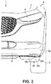
- An end of the protruding portion 32c on the vehicle-width-direction outer side thereof is located on the vehicle-width-direction inner side than the end surface of the front wheel 3 (the front wheel 3 on the left side here) on the vehicle-width-direction outer side thereof (see FIG. 2 and FIG. 3 ).
- the end surface of the protruding portion 32c on the rear side thereof may be formed by the longitudinal wall portion 32b (see FIG. 5 and FIG. 6 ).
- the distance between the lower end of the protruding portion 32c and the horizontal ground may be about 20 mm to about 300 mm or about 90 mm to about 200 mm, particularly about 110 mm.
- the end surface of the protruding portion 32c on the front side thereof to be hit by the traveling air includes a first inclined portion 32d provided in a portion including an end portion of the end surface on the vehicle-width-direction outer side thereof and inclined upward toward the front side, and a second inclined portion 32e located on the vehicle-width-direction inner side than the first inclined portion 32d and inclined upward toward the front side.
- the second inclined portion 32e may include an upper-side inclined portion 32f and a lower-side inclined portion 32g of which angles of inclination may be different from each other.
- An angle of inclination ⁇ 2 of the upper-side inclined portion 32f on the acute angle side thereof with respect to the horizontal direction may be set to be smaller than an angle of inclination ⁇ 3 of the lower-side inclined portion 32g on the acute angle side thereof with respect to the horizontal direction.
- the angles of inclination ⁇ 2 and ⁇ 3 of the second inclined portion 32e (the upper-side inclined portion 32f and the lower-side inclined portion 32g) on the acute angle side thereof with respect to the horizontal direction are set to be smaller than an angle of inclination ⁇ 1 of the first inclined portion 32d on the acute angle side thereof with respect to the horizontal direction.
- the second inclined portion 32e is located on the vehicle-width-direction inner side than the center of the front wheel 3 in the vehicle width direction.
- traveling air that has hit the first inclined portion 32d and traveling air that has hit the second inclined portion 32e may pass the first inclined portion 32d and the second inclined portion 32e, respectively, and head toward the rear side.
- traveling air that has hit the first inclined portion 32d and traveling air that has hit the second inclined portion 32e may flow to a lower side of the protruding portion 32c along the first inclined portion 32d and the second inclined portion 32e, respectively, and then head toward the rear side through the lower side of the protruding portion 32c.
- the traveling air that hits the end surface (the first inclined portion 32d and the second inclined portion 32e) of the protruding portion 32c on the front side thereof may flow toward the rear side and the vehicle-width-direction outer side before hitting the end surface.
- the traveling air that has hit the second inclined portion 32e basically hits the central portion of the front wheel 3 in the vehicle width direction after passing the second inclined portion 32e (see the flow of the traveling air indicated by an arrow F2).
- the traveling air that hits the first inclined portion 32d by flowing to the vehicle-width-direction outer side than the traveling air that hits the second inclined portion 32e also flows toward the rear side and the vehicle-width-direction outer side before hitting the first inclined portion 32d.
- the traveling air that has hit the first inclined portion 32d basically hits the portion of the front wheel 3 on the vehicle-width-direction outer side thereof after passing the first inclined portion 32d (see the flow of the traveling air indicated by an arrow Fl).
- the flow rate of the traveling air that hits the central portion of the front wheel 3 in the vehicle width direction after passing the second inclined portion 32e of which inclination is gentler than the first inclined portion 32d may be faster than the flow rate of the traveling air that hits the portion of the front wheel 3 on the vehicle-width-direction outer side thereof after passing the first inclined portion 32d.
- the pressure of the center space portion located immediately in front of the central portion of the front wheel 3 (the front wheel 3 on the left side here) in the vehicle width direction becomes higher than the pressure of the outer-side space portion located immediately in front of the portion of the front wheel 3 on the vehicle-width-direction outer side thereof.
- FIG. 7A illustrates a schematic pressure distribution in the vehicle width direction (the width direction of the front wheel 3) in the space portion immediately in front of the front wheel 3 at a height position, which is below the lower end of the protruding portion 32c of the deflector 30 and at which the traveling air that has passed the first inclined portion 32d and the second inclined portion 32e hits the front wheel 3, and the flow of the traveling air caused when the automobile 1 travels forward in this embodiment.
- FIG. 7A illustrates a schematic pressure distribution in the vehicle width direction (the width direction of the front wheel 3) in the space portion immediately in front of the front wheel 3 at a height position, which is below the lower end of the protruding portion 32c of the deflector 30 and at which the traveling air that has passed the first inclined portion 32d and the second inclined portion 32e hits the front wheel 3, and the flow of the traveling air caused when the automobile 1 travels forward in this embodiment.
- FIG. 7B illustrates a schematic pressure distribution in the vehicle width direction in the space portion immediately in front of the front wheel 3 at a height position, which is below the lower end of the wall portion of the deflector and at which the traveling air that has passed a wall portion that extends in the up-down direction hits the front wheel 3, and the flow of the traveling air caused when the automobile 1 travels forward in a related-art example using a deflector (see Japanese Patent Laid-Open No. 2017-77846 ) including the wall portion described above instead of the deflector 30.
- the pressure increases as the length of the arrow in the pressure distribution increases.
- the outlined arrows indicate the flow of the traveling air.
- the traveling air that has passed through the vehicle-width-direction outer side with respect to the wall portion of the deflector hits the portion of the front wheel 3 on the vehicle-width-direction outer side thereof. Therefore, as illustrated in FIG. 7B , at the height position, which is below the lower end of the wall portion of the deflector and at which the traveling air that has passed the wall portion hits the front wheel 3, the pressure of the outer-side space portion becomes higher than the pressure of the center space portion.
- the traveling air avoids the outer-side space portion, and flows toward the rear side and the vehicle-width-direction outer side so as to be spaced apart from the outer-side space portion.
- the traveling air flowing as above does not flow along the end surface of the front wheel 3 on the vehicle-width-direction outer side thereof, and flows to the rear side so as to be spaced apart from the end surface. Therefore, a separating flow (swirl) is easily generated in the vicinity of the end surface of the front wheel 3 on the vehicle-width-direction outer side thereof with the deflector of the related-art example.
- the pressure of the outer-side space portion is lower than the pressure of the center space portion.
- the traveling air avoids the center space portion of which pressure is high and easily flows to the outer-side space portion of which pressure is low. Therefore, in the space portion on the front side of the front wheel 3, the traveling air flows toward the rear side and the vehicle-width-direction outer side so as to flow from the center space portion side toward the outer-side space portion side.
- the traveling air flowing from the center space portion side toward the outer-side space portion side flows to the rear side along the end surface of the front wheel 3 on the vehicle-width-direction outer side thereof. Therefore, it is difficult for a separating flow (swirl) to be generated in the vicinity of the end surface of the front wheel 3 on the vehicle-width-direction outer side thereof. Thus, the air resistance of the automobile 1 can be reduced.
- the pressure of the inner-side space portion located immediately in front of the portion of the front wheel 3 on the vehicle-width-direction inner side thereof is also lower than the pressure of the center space portion, but the pressure of the inner-side space portion may be higher than the pressure of the center space portion.
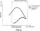
- FIG. 8 shows results obtained by measuring the pressure distribution in the vehicle width direction in the space portion immediately in front of the front wheel 3 at the height position (the height position in the center between the lower end of the protruding portion 32c and the ground here), which is below the lower end of the protruding portion 32c of the deflector 30 and at which the traveling air that has passed the first inclined portion 32d and the second inclined portion 32e hits the front wheel 3, in this embodiment, and the pressure distribution in the vehicle width direction in the space portion immediately in front of the front wheel 3 at the height position (the height position in the center between the lower end of the wall portion described above and the ground here), which is below the lower end of the wall portion of the deflector and at which the traveling air that has passed the wall portion hits the front wheel 3, in the related-art example described above.
- the speed of the automobile at the time of measurement is about 100 km/h for both cases. It can be understood that the results of the measurement are substantially the same as the schematic pressure distributions illustrated in FIG. 7A and FIG. 7B . Note that the pressure is basically higher in this embodiment than in the related-art example due to the following reason. In the related-art example, the flow rate of the traveling air considerably decreases by the wall portion. Meanwhile, in this embodiment, the traveling air easily passes the first inclined portion 32d and the second inclined portion 32e, and the flow rate of the traveling air does not decrease as in the related-art example.
- the angles of inclination ⁇ 2 and ⁇ 3 of the second inclined portion 32e (the upper-side inclined portion 32f and the lower-side inclined portion 32g) of the protruding portion 32c described above are smaller than the angle of inclination ⁇ 1 of the first inclined portion 32d described above, and hence the pressure of the outer-side space portion becomes lower than the pressure of the center space portion at the height position, which is below the lower end of the protruding portion 32c of the deflector 30 and at which the traveling air that has passed the first inclined portion 32d and the second inclined portion 32e hits the front wheel 3.
- the traveling air flows toward the rear side and the vehicle-width-direction outer side so as to head toward the outer-side space portion side from the center space portion side, and the traveling air flowing from the center space portion side toward the outer-side space portion side flows along the end surface of the front wheel 3 on the vehicle-width-direction outer side thereof. Therefore, the air resistance of the automobile 1 can be reduced.
- the present invention is useful as a deflector structure for an automobile including a deflector mounted on a lower surface ahead of a front wheel well in the automobile, particularly in a vehicle front-rear direction, so as to be spaced apart from a front wheel at a position ahead of the front wheel.
Landscapes
- Engineering & Computer Science (AREA)
- Chemical & Material Sciences (AREA)
- Combustion & Propulsion (AREA)
- Transportation (AREA)
- Mechanical Engineering (AREA)
- Body Structure For Vehicles (AREA)
Abstract
Description
- The present invention belongs to a technical field relating to a deflector structure for an automobile and an automobile.
- Hitherto, the turbulence of the air flow caused by front wheels has been suppressed in order to improve fuel efficiency of an automobile. The turbulence of the air flow is caused when traveling air that flows under the floor of the front portion of the automobile and reaches the front wheels when the automobile travels forward is disturbed by the rotation of the front wheels.
- For example, in Japanese Patent Laid-Open No.
2017-77846 - The inventors of the present invention have performed eager analysis for further improvement of aerodynamic characteristics. As a result, the following matter has become clear. Even when the deflector as that in Japanese Patent Laid-Open No.
2017-77846 - The present invention has been made in view of the points as above, and an object thereof is to properly improve in reducing air resistance of the automobile by causing traveling air caused when the automobile travels forward to flow along an end surface of a front wheel on a vehicle-width-direction outer side thereof.
- The invention is defined by the independent claims. Particular embodiments are defined in the dependent claims. In particular, there is provided a deflector mounted on a lower surface ahead of a front wheel well in the automobile, particularly in a vehicle front-rear direction, so as to be spaced apart from a front wheel at a position ahead of the front wheel. A protruding portion protruding downward and having an end surface on an automobile front side of the protruding portion is provided on a lower surface of the deflector, the end surface is configured to be hit by traveling air caused when the automobile travels forward is provided on a lower surface of the deflector. The end surface of the protruding portion on the automobile front side of the protruding portion includes: a first inclined portion provided on a portion including an end portion of the end surface on a vehicle-width-direction outer side of the end surface and inclined upward toward the automobile front side; and a second inclined portion located on a vehicle-width-direction inner side than the first inclined portion and inclined upward toward the automobile front side. An angle of inclination of the second inclined portion on an acute angle side of the second inclined portion with respect to a horizontal direction is set to be smaller than an angle of inclination of the first inclined portion on an acute angle side of the first inclined portion with respect to the horizontal direction.
- Particularly, the deflector structure is configured to guide traveling air that hits the first inclined portion and the second inclined portion to a lower side of the protruding portion along the first inclined portion and the second inclined portion, respectively, such that traveling air can head toward an automobile rear side of the protruding portion through the lower side of the protruding portion. In other words, traveling air may flow to the lower side along the first inclined portion and the second inclined portion, and then head toward the automobile rear side of the protruding portion through the lower side of the protruding portion. The traveling air that has passed the first inclined portion can be basically caused to hit the portion of the front wheel on the vehicle-width-direction outer side thereof and the traveling air that has passed the second inclined portion can be basically caused to hit the central portion of the front wheel in the vehicle width direction. Further particularly, the deflector structure is configured to set a flow rate of the traveling air that hits a central portion of the front wheel in a vehicle width direction after passing the second inclined portion to be faster than a flow rate of the traveling air that hits a portion of the front wheel on the vehicle-width-direction outer side thereof after passing the first inclined portion. In other words, the flow rate of the traveling air that hits the central portion of the front wheel in the vehicle width direction after passing the second inclined portion of which inclination is gentler than the first inclined portion may be faster than the flow rate of the traveling air that hits the portion of the front wheel on the vehicle-width-direction outer side thereof after passing the first inclined portion. As a result, at the height position, which is below the lower end of the protruding portion of the deflector and at which the traveling air that has passed the first inclined portion and the second inclined portion hits the front wheel, the pressure of the center space portion located immediately in front of the central portion of the front wheel in the vehicle width direction becomes higher than the pressure of the outer-side space portion located immediately in front of the portion of the front wheel on the vehicle-width-direction outer side thereof. When a pressure distribution as above is formed, the traveling air avoids the center space portion of which pressure is high and easily flows to the outer-side space portion of which pressure is low. Therefore, in the space portion on the front side of the front wheel, the traveling air flows toward the rear side and the vehicle-width-direction outer side so as to head toward the outer-side space portion side from the center space portion side. The traveling air flowing from the center space portion side toward the outer-side space portion side flows to the rear side along the end surface of the front wheel on the vehicle-width-direction outer side thereof. Therefore, it is difficult for a separating flow (swirl) to be generated in the vicinity of the end surface of the front wheel on the vehicle-width-direction outer side thereof. Thus, the air resistance of the automobile can be reduced.
- In one embodiment of the deflector structure for the automobile described above, the second inclined portion may be located on the vehicle-width-direction inner side than a center of the front wheel in a vehicle width direction.
- In other words, the traveling air that hits the second inclined portion generally flows toward the automobile rear side and the vehicle-width-direction outer side by the round shape of the corner portion on the end portion of the front bumper in the vehicle width direction before hitting the second inclined portion. As a result, since the second inclined portion is located on the vehicle-width-direction inner side than the center of the front wheel in the vehicle width direction, the traveling air that has passed the second inclined portion basically hits the central portion of the front wheel in the vehicle width direction.
- When the second inclined portion is located on the vehicle-width-direction inner side than the center of the front wheel in the vehicle width direction, the deflector may be mounted at least partially on a lower surface of a corner portion on an end portion of a front bumper of the automobile in the vehicle width direction, and the corner portion may be formed in a round shape so as to be positioned rearward toward the vehicle-width-direction outer side in a bottom view of the automobile.
- As a result, the traveling air that has passed the second inclined portion hits the central portion of the front wheel in the vehicle width direction in a more secured manner.
- Particularly, the deflector structure is configured to guide traveling air that hits the end surface of the protruding portion on the automobile front side thereof toward an automobile rear side of the protruding portion and the vehicle-width-direction outer side before hitting the end surface.
- Further particularly, the second inclined portion includes an upper-side inclined portion and a lower-side inclined portion of which angles of inclination are different from each other.
- Further particularly, an angle of inclination of the upper-side inclined portion on the acute angle side thereof with respect to the horizontal direction is set to be smaller than an angle of inclination of the lower-side inclined portion on the acute angle side thereof with respect to the horizontal direction.
- Further particularly, the end surface of the protruding portion on an automobile rear side of the protruding portion thereof is formed by a longitudinal wall portion.
- Further particularly, the deflector is formed by two members including an upper member and a lower member that are an upper-side member and a lower-side member.
- Further particularly, the upper-side member is formed by a metal plate material, and/or the lower-side member is formed by soft synthetic resin.
- Further particularly, an automobile includes a deflector structure for an automobile.
- Further particularly, the automobile further includes a left and right of deflectors provided on a lower surface of the front portion of the automobile in a vehicle front-rear direction.
- Further particularly, the left and right deflectors are attached to substantially symmetrical positions with respect to the center of the automobile in a vehicle width direction and are formed in substantially symmetrical shapes with respect to the center of the automobile in the vehicle width direction.
- As described above, the deflector structure for the automobile according to the aspect of the present invention causes, at the height position that is below the lower end of the protruding portion of the deflector and at which the traveling air that has passed the first inclined portion and the second inclined portion hits the front wheel, the pressure of the outer-side space portion located immediately in front of the portion of the front wheel on the vehicle-width-direction outer side thereof to become lower than the pressure of the center space portion located immediately in front of the central portion of the front wheel in the vehicle width direction. Thus, in the space portion on the front side of the front wheel, the traveling air caused when the automobile travels forward flows toward the rear side and the vehicle-width-direction outer side so as to head toward the outer-side space portion side from the center space portion side, and the traveling air flowing from the center space portion side toward the outer-side space portion side flows along the end surface of the front wheel on the vehicle-width-direction outer side thereof. As a result, the air resistance of the automobile can be reduced.
-
-
FIG. 1 is a perspective view illustrating a part (left-front-side portion) of a front portion of an automobile in which a deflector structure according to an embodiment of the present invention is employed; -
FIG. 2 is a front view of the left-front-side portion of the automobile described above; -
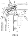
FIG. 3 is a bottom view of the left-front-side portion of the automobile described above; -
FIG. 4 is a bottom view illustrating a lower-side member in the deflector on the left side; -
FIG. 5 is a cross-sectional view taken along line V-V inFIG. 4 ; -
FIG. 6 is a cross-sectional view taken along line VI-VI inFIG. 4 ; -
FIG. 7A illustrates a schematic pressure distribution in the vehicle width direction in a space portion immediately in front of a front wheel at a height position, which is below a lower end of a protruding portion of the deflector and at which traveling air that has passed a first inclined portion and a second inclined portion hits the front wheel, and the flow of the traveling air caused when the automobile travels forward in this embodiment; -
FIG. 7B illustrates a schematic pressure distribution in the vehicle width direction in a space portion immediately in front of a front wheel at a height position, which is below a lower end of a wall portion of a deflector of the related art and at which traveling air that has passed the wall portion hits the front wheel, and the flow of the traveling air caused when the automobile travels forward in a related-art example using the deflector of the related art instead of the deflector of this embodiment; and -
FIG. 8 is a graph showing results obtained by measuring the pressure distribution in the vehicle width direction in the space portion immediately in front of the front wheel at the height position, which is below the lower end of the protruding portion of the deflector and at which the traveling air that has passed the first inclined portion and the second inclined portion hits the front wheel, in this embodiment, and the pressure distribution in the vehicle width direction in the space portion immediately in front of the front wheel at the height position, which is below the lower end of the wall portion of the deflector of the related art and at which the traveling air that has passed the wall portion hits the front wheel, in the related-art example described above. - An embodiment of the present invention is described in detail below on the basis of the drawings.
-
FIG. 1 to FIG. 3 illustrate a part (left-front-side portion) of afront portion 2 of an automobile 1 in which a deflector structure according to the embodiment of the present invention is employed. "Front", "rear", "left", "right", "upper", and "lower" with respect to the automobile 1 are simply referred to as "front", "rear", "left", "right", "upper", and "lower" below. In the description below, only the left side is illustrated for components that form a left-and-right pair (for example, front wheels 3). Note that, inFIG. 1 , arrow Fr indicates a direction ahead of the automobile 1 (the same applies toFIG. 3 to FIG. 6 ,FIG. 7A, and FIG. 7B ). - The
front portion 2 of the automobile 1 is a portion anterior to a passenger compartment which a driver of the automobile 1 gets into, and includes a mounting space (including an engine compartment) in which components relating to the traveling of the automobile 1 such as an engine, a transmission, a cooling apparatus, a suspension apparatus, a steering apparatus, and the left-and-right pair of thefront wheels 3 are mounted, and lights toward ahead or sides of the automobile 1 such asheadlights 4 and fog lamps. - The
front portion 2 of the automobile 1 includes a left-and-right pair of front fenders 5 forming the side surfaces on both of left and right sides of thefront portion 2, afront bumper 6 disposed on the front ends of the left-and-right pair of front fenders 5 (the front end of the automobile 1), and a hood 7 covering an upward opening of the mounting space (engine compartment) described above surrounded by the left-and-right pair of front fenders 5 and thefront bumper 6. - Both end portions of the
front bumper 6 in the vehicle width direction (left and right direction) arecorner portions 6a that go around the sides on both of left and right sides from the front end of the automobile 1. The left andright corner portions 6a are each formed in a round shape so as to be positioned rearward toward the vehicle-width-direction outer sides in a bottom view of the automobile 1 (seeFIG. 3 ). - A left-and-right pair of
front wheel wells 8 in which the left and rightfront wheels 3 are accommodated are provided in the lower sides of the left and right front fenders 5. Thefront wheel wells 8 are covered withmud guards 9, and themud guards 9 prevent mud, pebbles, and water drops splashed by thefront wheels 3 from entering the mounting space described above. For example, themud guards 9 are made of hard synthetic resin such as polypropylene, and are formed in a substantially arc shape so as to extend along the upper-side portions of thefront wheels 3 in a side view of the automobile 1. - On the lower surface (bottom surface) in the
front portion 2 of the automobile 1, a front-side undercover 21, and a rear-side undercover 22 located on the rear side thereof are provided. The rear-side undercover 22 is located on the front side of a suspension cross member (not shown) that extends in the vehicle width direction, and covers the lower side of the engine described above. - As illustrated in
FIG. 1 to FIG. 3 , a left-and-right pair of deflectors 30 (left and right deflectors) may be provided on the lower surface of thefront portion 2 of the automobile 1 in a vehicle front-rear direction. Each of thedeflectors 30 are provided in a portion surrounded by the front end of the front wheel well 8 (the front end of the mud guard 9), thefront bumper 6, and the front-side undercover 21. In other words, thedeflector 30 is provided on the lower surface ahead of the front wheel well 8 in the automobile 1, particularly in a vehicle front-rear direction, so as to be spaced apart from afront wheel 3 at a position ahead of thefront wheel 3. Thedeflectors 30 reduce the air resistance of the automobile 1 by controlling the flow of the traveling air caused when the automobile 1 travels forward. - The left and
right deflectors 30 may be attached to substantially symmetrical positions with respect to the center of the automobile 1 in the vehicle width direction and may be formed in substantially symmetrical shapes with respect to the center of the automobile 1 in the vehicle width direction. The configurations of the left andright deflectors 30 are basically the same, and hence thedeflector 30 on the left side is described in detail below. The expressions of "front", "rear", "left", "right", "upper", and "lower" with respect to thedeflector 30 on the left side described below are "front", "rear", "left", "right", "upper", and "lower" in a state in which thedeflector 30 on the left side is provided on the automobile 1, and are the same as "front", "rear", "left", "right", "upper", and "lower" with respect to the automobile 1. - In this embodiment, the
deflector 30 on the left side (hereinafter referred to as the deflector 30) is formed by two members including an upper member and a lower member that are an upper-side member 31 and a lower-side member 32. The upper-side member 31 may be formed by a metal plate material, and/or the lower-side member 32 may be formed by soft synthetic resin such as synthetic rubber having flexibility. - The upper-
side member 31 includes acurved edge portion 31a from the front end to the end on the vehicle-width-direction outer side formed in a shape (round shape) similar to thecorner portion 6a of thefront bumper 6 in a bottom view of the automobile 1 (seeFIG. 3 andFIG. 4 ). Thecurved edge portion 31a is mounted and fixed on the lower surface of thecorner portion 6a bybolts 37 at a plurality of places. The rear end edge portion of the upper-side member 31 is abent portion 31b (seeFIG. 5 andFIG. 6 ) that is bent upward. - The lower-
side member 32 includes acurved edge portion 32a (seeFIG. 3 andFIG. 4 ) formed in a round shape as with thecurved edge portion 31a and located on the inner side of thecurved edge portion 31a of the upper-side member 31. Thecurved edge portion 32a is mounted and fixed to the upper-side member 31 byclips 38 at a plurality of places. - An end edge portion of the lower-
side member 32 on the vehicle-width-direction inner side thereof vertically overlaps with an end edge portion of the upper-side member 31 on the vehicle-width-direction inner side thereof, and is mounted and fixed on the upper-side member 31 bybolts 39 at a plurality of places. The end edge portions of the upper-side member 31 and the lower-side member 32 on the vehicle-width-direction inner side thereof are supported on the front-side undercover 21 and the rear-side undercover 22. - The rear end edge portion of the lower-
side member 32 is avertical wall portion 32b (seeFIG. 5 andFIG. 6 ) rising to the upper side, and thevertical wall portion 32b is mounted and fixed on thebent portion 31b of the upper-side member 31 by clips (not shown) at a plurality of places in the vehicle width direction. A front end portion of themud guard 9 is also mounted and fixed on thebent portion 31b together with thevertical wall portion 32b by the clips. - On a portion that is a rear-side end portion of the lower surface of the deflector 30 (the lower surface of the lower-side member 32) and is on the vehicle-width-direction outer side, a protruding
portion 32c that protrudes downward and has an end surface on the front side thereof to which the traveling air caused when the automobile 1 travels forward hits is provided. An end of the protrudingportion 32c on the vehicle-width-direction outer side thereof is located on the vehicle-width-direction inner side than the end surface of the front wheel 3 (thefront wheel 3 on the left side here) on the vehicle-width-direction outer side thereof (seeFIG. 2 andFIG. 3 ). The end surface of the protrudingportion 32c on the rear side thereof may be formed by thelongitudinal wall portion 32b (seeFIG. 5 andFIG. 6 ). Note that, in this embodiment, the distance between the lower end of the protrudingportion 32c and the horizontal ground may be about 20 mm to about 300 mm or about 90 mm to about 200 mm, particularly about 110 mm. - In this embodiment, as illustrated in
FIG. 5 andFIG. 6 , the end surface of the protrudingportion 32c on the front side thereof to be hit by the traveling air includes a firstinclined portion 32d provided in a portion including an end portion of the end surface on the vehicle-width-direction outer side thereof and inclined upward toward the front side, and a secondinclined portion 32e located on the vehicle-width-direction inner side than the firstinclined portion 32d and inclined upward toward the front side. The secondinclined portion 32e may include an upper-sideinclined portion 32f and a lower-sideinclined portion 32g of which angles of inclination may be different from each other. An angle of inclination θ2 of the upper-sideinclined portion 32f on the acute angle side thereof with respect to the horizontal direction may be set to be smaller than an angle of inclination θ3 of the lower-sideinclined portion 32g on the acute angle side thereof with respect to the horizontal direction. The angles of inclination θ2 and θ3 of the secondinclined portion 32e (the upper-sideinclined portion 32f and the lower-sideinclined portion 32g) on the acute angle side thereof with respect to the horizontal direction are set to be smaller than an angle of inclination θ1 of the firstinclined portion 32d on the acute angle side thereof with respect to the horizontal direction. In this embodiment, the secondinclined portion 32e is located on the vehicle-width-direction inner side than the center of thefront wheel 3 in the vehicle width direction. - Traveling air that has hit the first
inclined portion 32d and traveling air that has hit the secondinclined portion 32e may pass the firstinclined portion 32d and the secondinclined portion 32e, respectively, and head toward the rear side. In other words, traveling air that has hit the firstinclined portion 32d and traveling air that has hit the secondinclined portion 32e may flow to a lower side of the protrudingportion 32c along the firstinclined portion 32d and the secondinclined portion 32e, respectively, and then head toward the rear side through the lower side of the protrudingportion 32c. - By the round shape of the
corner portion 6a on the end portion of thefront bumper 6 in the vehicle width direction, the traveling air that hits the end surface (the firstinclined portion 32d and the secondinclined portion 32e) of the protrudingportion 32c on the front side thereof may flow toward the rear side and the vehicle-width-direction outer side before hitting the end surface. As a result, since the secondinclined portion 32e is located on the vehicle-width-direction inner side than the center of thefront wheel 3 in the vehicle width direction, the traveling air that has hit the secondinclined portion 32e basically hits the central portion of thefront wheel 3 in the vehicle width direction after passing the secondinclined portion 32e (see the flow of the traveling air indicated by an arrow F2). - Meanwhile, the traveling air that hits the first
inclined portion 32d by flowing to the vehicle-width-direction outer side than the traveling air that hits the secondinclined portion 32e also flows toward the rear side and the vehicle-width-direction outer side before hitting the firstinclined portion 32d. As a result, the traveling air that has hit the firstinclined portion 32d basically hits the portion of thefront wheel 3 on the vehicle-width-direction outer side thereof after passing the firstinclined portion 32d (see the flow of the traveling air indicated by an arrow Fl). - The flow rate of the traveling air that hits the central portion of the
front wheel 3 in the vehicle width direction after passing the secondinclined portion 32e of which inclination is gentler than the firstinclined portion 32d may be faster than the flow rate of the traveling air that hits the portion of thefront wheel 3 on the vehicle-width-direction outer side thereof after passing the firstinclined portion 32d. As a result, at a height position (for example, the height position near the center between the lower end of the protrudingportion 32c and the ground), which is below the lower end of the protrudingportion 32c of thedeflector 30 and at which the traveling air that has passed the firstinclined portion 32d and the secondinclined portion 32e hits thefront wheel 3, the pressure of the center space portion located immediately in front of the central portion of the front wheel 3 (thefront wheel 3 on the left side here) in the vehicle width direction becomes higher than the pressure of the outer-side space portion located immediately in front of the portion of thefront wheel 3 on the vehicle-width-direction outer side thereof. -
FIG. 7A illustrates a schematic pressure distribution in the vehicle width direction (the width direction of the front wheel 3) in the space portion immediately in front of thefront wheel 3 at a height position, which is below the lower end of the protrudingportion 32c of thedeflector 30 and at which the traveling air that has passed the firstinclined portion 32d and the secondinclined portion 32e hits thefront wheel 3, and the flow of the traveling air caused when the automobile 1 travels forward in this embodiment.FIG. 7B illustrates a schematic pressure distribution in the vehicle width direction in the space portion immediately in front of thefront wheel 3 at a height position, which is below the lower end of the wall portion of the deflector and at which the traveling air that has passed a wall portion that extends in the up-down direction hits thefront wheel 3, and the flow of the traveling air caused when the automobile 1 travels forward in a related-art example using a deflector (see Japanese Patent Laid-Open No.2017-77846 deflector 30. InFIG. 7A and FIG. 7B , the pressure increases as the length of the arrow in the pressure distribution increases. InFIG. 7A and FIG. 7B , the outlined arrows indicate the flow of the traveling air. - In the related-art example described above, the traveling air that has passed through the vehicle-width-direction outer side with respect to the wall portion of the deflector hits the portion of the
front wheel 3 on the vehicle-width-direction outer side thereof. Therefore, as illustrated inFIG. 7B , at the height position, which is below the lower end of the wall portion of the deflector and at which the traveling air that has passed the wall portion hits thefront wheel 3, the pressure of the outer-side space portion becomes higher than the pressure of the center space portion. When a pressure distribution as above is formed, the traveling air avoids the outer-side space portion, and flows toward the rear side and the vehicle-width-direction outer side so as to be spaced apart from the outer-side space portion. The traveling air flowing as above does not flow along the end surface of thefront wheel 3 on the vehicle-width-direction outer side thereof, and flows to the rear side so as to be spaced apart from the end surface. Therefore, a separating flow (swirl) is easily generated in the vicinity of the end surface of thefront wheel 3 on the vehicle-width-direction outer side thereof with the deflector of the related-art example. - Meanwhile, in this embodiment, as illustrated in
FIG. 7A , at the height position, which is below the lower end of the protrudingportion 32c of thedeflector 30 and at which the traveling air that has passed the firstinclined portion 32d and the secondinclined portion 32e hits thefront wheel 3, the pressure of the outer-side space portion is lower than the pressure of the center space portion. When the pressure distribution as above is formed, the traveling air avoids the center space portion of which pressure is high and easily flows to the outer-side space portion of which pressure is low. Therefore, in the space portion on the front side of thefront wheel 3, the traveling air flows toward the rear side and the vehicle-width-direction outer side so as to flow from the center space portion side toward the outer-side space portion side. The traveling air flowing from the center space portion side toward the outer-side space portion side flows to the rear side along the end surface of thefront wheel 3 on the vehicle-width-direction outer side thereof. Therefore, it is difficult for a separating flow (swirl) to be generated in the vicinity of the end surface of thefront wheel 3 on the vehicle-width-direction outer side thereof. Thus, the air resistance of the automobile 1 can be reduced. Note that, in this embodiment, the pressure of the inner-side space portion located immediately in front of the portion of thefront wheel 3 on the vehicle-width-direction inner side thereof is also lower than the pressure of the center space portion, but the pressure of the inner-side space portion may be higher than the pressure of the center space portion. -
FIG. 8 shows results obtained by measuring the pressure distribution in the vehicle width direction in the space portion immediately in front of thefront wheel 3 at the height position (the height position in the center between the lower end of the protrudingportion 32c and the ground here), which is below the lower end of the protrudingportion 32c of thedeflector 30 and at which the traveling air that has passed the firstinclined portion 32d and the secondinclined portion 32e hits thefront wheel 3, in this embodiment, and the pressure distribution in the vehicle width direction in the space portion immediately in front of thefront wheel 3 at the height position (the height position in the center between the lower end of the wall portion described above and the ground here), which is below the lower end of the wall portion of the deflector and at which the traveling air that has passed the wall portion hits thefront wheel 3, in the related-art example described above. The speed of the automobile at the time of measurement is about 100 km/h for both cases. It can be understood that the results of the measurement are substantially the same as the schematic pressure distributions illustrated inFIG. 7A and FIG. 7B . Note that the pressure is basically higher in this embodiment than in the related-art example due to the following reason. In the related-art example, the flow rate of the traveling air considerably decreases by the wall portion. Meanwhile, in this embodiment, the traveling air easily passes the firstinclined portion 32d and the secondinclined portion 32e, and the flow rate of the traveling air does not decrease as in the related-art example. - Therefore, in this embodiment, the angles of inclination θ2 and θ3 of the second
inclined portion 32e (the upper-sideinclined portion 32f and the lower-sideinclined portion 32g) of the protrudingportion 32c described above are smaller than the angle of inclination θ1 of the firstinclined portion 32d described above, and hence the pressure of the outer-side space portion becomes lower than the pressure of the center space portion at the height position, which is below the lower end of the protrudingportion 32c of thedeflector 30 and at which the traveling air that has passed the firstinclined portion 32d and the secondinclined portion 32e hits thefront wheel 3. As a result, in the space portion on the front side of thefront wheel 3, the traveling air flows toward the rear side and the vehicle-width-direction outer side so as to head toward the outer-side space portion side from the center space portion side, and the traveling air flowing from the center space portion side toward the outer-side space portion side flows along the end surface of thefront wheel 3 on the vehicle-width-direction outer side thereof. Therefore, the air resistance of the automobile 1 can be reduced. - The present invention is not limited to the embodiment described above, and substitution is possible without departing from the gist of the claims.
- The embodiment described above is merely an example, and the scope of the invention is not to be interpreted in a limited manner. The scope of the present invention is defined by the independent claims.
- The present invention is useful as a deflector structure for an automobile including a deflector mounted on a lower surface ahead of a front wheel well in the automobile, particularly in a vehicle front-rear direction, so as to be spaced apart from a front wheel at a position ahead of the front wheel.
-
- 1
- automobile
- 3
- front wheel
- 6
- front bumper
- 6a
- corner portion
- 8
- front wheel well
- 30
- deflector
- 32c
- protruding portion
- 32d
- first inclined portion
- 32e
- second inclined portion
Claims (14)
- A deflector structure for an automobile (1), the deflector structure comprising a deflector (30) mounted on a lower surface ahead of a front wheel well (8) in the automobile (1) so as to be spaced apart from a front wheel (3) at a position ahead of the front wheel (3), wherein:a protruding portion (32c) protruding downward and having an end surface on an automobile front side of the protruding portion (32c) is provided on a lower surface of the deflector (30), the end surface is configured to be hit by traveling air caused when the automobile (1) travels forward;the end surface of the protruding portion (32c) on the automobile front side of the protruding portion (32c) comprises:a first inclined portion (32d) provided on a portion comprising an end portion of the end surface on a vehicle-width-direction outer side of the end surface and inclined upward toward the automobile front side; anda second inclined portion (32e) located on a vehicle-width-direction inner side than the first inclined portion (32d) and inclined upward toward the automobile front side; andan angle of inclination of the second inclined portion (32e) on an acute angle side of the second inclined portion (32e) with respect to a horizontal direction is set to be smaller than an angle of inclination of the first inclined portion (32d) on an acute angle side of the first inclined portion (32d) with respect to the horizontal direction.
- The deflector structure for the automobile (1) according to claim 1, wherein
the second inclined portion (32e) is located on the vehicle-width-direction inner side than a center of the front wheel (3) in a vehicle width direction. - The deflector structure for the automobile (1) according to any one of the preceding claims, wherein
the deflector structure is configured to guide traveling air that hits the first inclined portion (32d) and the second inclined portion (32e) to a lower side of the protruding portion (32c) along the first inclined portion (32d) and the second inclined portion (32e), respectively, such that traveling air can head toward an automobile rear side of the protruding portion (32c) through the lower side of the protruding portion (32c). - The deflector structure for the automobile (1) according to any one of the preceding claims, wherein:the deflector (30) is mounted at least partially on a lower surface of a corner portion (6a) on an end portion of a front bumper (6) of the automobile (1) in the vehicle width direction; andthe corner portion (6a) is formed in a round shape so as to be positioned rearward toward the vehicle-width-direction outer side in a bottom view of the automobile (1) .
- The deflector structure for the automobile (1) according to any one of the preceding claims, wherein
the deflector structure is configured to guide traveling air that hits the end surface of the protruding portion (32c) on the automobile front side thereof toward an automobile rear side of the protruding portion (32c) and the vehicle-width-direction outer side before hitting the end surface. - The deflector structure for the automobile (1) according to any one of the preceding claims, wherein
the deflector structure is configured to set a flow rate of the traveling air that hits a central portion of the front wheel (3) in a vehicle width direction after passing the second inclined portion (32e) to be faster than a flow rate of the traveling air that hits a portion of the front wheel (3) on the vehicle-width-direction outer side thereof after passing the first inclined portion (32d). - The deflector structure for the automobile (1) according to any one of the preceding claims, wherein
the second inclined portion (32e) includes an upper-side inclined portion (32f) and a lower-side inclined portion (32g) of which angles of inclination are different from each other. - The deflector structure for the automobile (1) according to claim 7, wherein
an angle of inclination of the upper-side inclined portion (32f) on the acute angle side thereof with respect to the horizontal direction is set to be smaller than an angle of inclination of the lower-side inclined portion (32g) on the acute angle side thereof with respect to the horizontal direction. - The deflector structure for the automobile (1) according to any one of the preceding claims, wherein
the end surface of the protruding portion (32c) on an automobile rear side of the protruding portion (32c) thereof is formed by a longitudinal wall portion (32b). - The deflector structure for the automobile (1) according to any one of the preceding claims, wherein
the deflector (30) is formed by two members including an upper member and a lower member that are an upper-side member (31) and a lower-side member (32). - The deflector structure for the automobile (1) according to claim 10, wherein
the upper-side member (31) is formed by a metal plate material, and/or the lower-side member (32) is formed by soft synthetic resin. - An automobile comprising:
a deflector structure for an automobile of any one of the preceding claims. - The automobile according to claim 12, the automobile further comprising:
a left and right of deflectors (30) provided on a lower surface of the front portion (2) of the automobile (1) in a vehicle front-rear direction. - The automobile according to claim 13, wherein
the left and right deflectors (30) are attached to substantially symmetrical positions with respect to a center of the automobile (1) in a vehicle width direction and are formed in substantially symmetrical shapes with respect to the center of the automobile (1) in the vehicle width direction.
Applications Claiming Priority (1)
| Application Number | Priority Date | Filing Date | Title |
|---|---|---|---|
| JP2018242859A JP7176404B2 (en) | 2018-12-26 | 2018-12-26 | automobile deflector structure |
Publications (2)
| Publication Number | Publication Date |
|---|---|
| EP3702255A1 true EP3702255A1 (en) | 2020-09-02 |
| EP3702255B1 EP3702255B1 (en) | 2022-09-28 |
Family
ID=68917662
Family Applications (1)
| Application Number | Title | Priority Date | Filing Date |
|---|---|---|---|
| EP19216620.5A Active EP3702255B1 (en) | 2018-12-26 | 2019-12-16 | Deflector structure for automobile, and automobile |
Country Status (4)
| Country | Link |
|---|---|
| US (1) | US11077893B2 (en) |
| EP (1) | EP3702255B1 (en) |
| JP (1) | JP7176404B2 (en) |
| CN (1) | CN111376999B (en) |
Families Citing this family (6)
| Publication number | Priority date | Publication date | Assignee | Title |
|---|---|---|---|---|
| EP3578446B1 (en) * | 2017-03-06 | 2022-08-10 | Mazda Motor Corporation | Tire deflector device |
| JP6477762B2 (en) * | 2017-03-28 | 2019-03-06 | マツダ株式会社 | Front body structure of the vehicle |
| DE102020007450B4 (en) * | 2020-12-07 | 2024-09-05 | Mercedes-Benz Group AG | Air guiding device for a motor vehicle, in particular for a passenger car, and motor vehicles |
| JP7647270B2 (en) * | 2021-04-13 | 2025-03-18 | マツダ株式会社 | Vehicle front structure |
| USD1041371S1 (en) * | 2022-06-30 | 2024-09-10 | Randy Helmick | Car spoiler device |
| CN116039781B (en) * | 2023-01-18 | 2024-05-14 | 重庆赛力斯新能源汽车设计院有限公司 | A spoiler for a front wheel cover of a car capable of reducing wind resistance and a car |
Citations (5)
| Publication number | Priority date | Publication date | Assignee | Title |
|---|---|---|---|---|
| WO2016083682A1 (en) * | 2014-11-26 | 2016-06-02 | Peugeot Citroen Automobiles Sa | Vehicle with air deflector for wheel |
| US20170057567A1 (en) * | 2015-08-25 | 2017-03-02 | Honda Motor Co., Ltd. | Resistance reduction member |
| JP2017077846A (en) | 2015-10-22 | 2017-04-27 | マツダ株式会社 | Car deflector structure |
| WO2018163803A1 (en) * | 2017-03-06 | 2018-09-13 | マツダ株式会社 | Tire deflector device |
| WO2018180026A1 (en) * | 2017-03-28 | 2018-10-04 | マツダ株式会社 | Front body structure of vehicle |
Family Cites Families (10)
| Publication number | Priority date | Publication date | Assignee | Title |
|---|---|---|---|---|
| DE10213188A1 (en) * | 2002-03-23 | 2003-10-02 | Porsche Ag | Motor vehicle has air outlet opening located in one of transverse wall of wheel arch allocated to front wheel and to which is connected air guiding channel leading out to open air |
| DE102004061835A1 (en) | 2004-12-22 | 2006-07-06 | Bayerische Motoren Werke Ag | spoiler device |
| CN102822043B (en) * | 2010-04-08 | 2015-04-01 | 日产自动车株式会社 | Front underfloor structure of vehicle |
| JP5516724B2 (en) * | 2010-04-08 | 2014-06-11 | 日産自動車株式会社 | Vehicle front underfloor structure |
| FR2975964B1 (en) * | 2011-05-31 | 2013-07-05 | Peugeot Citroen Automobiles Sa | MOTOR VEHICLE COMPRISING AERODYNAMIC MEANS POSITIONED IN FRONT OF A WHEEL AND ITS BRAKING DEVICE |
| JP5712994B2 (en) * | 2012-12-11 | 2015-05-07 | トヨタ自動車株式会社 | Vehicle lower structure |
| JP6060916B2 (en) * | 2014-02-12 | 2017-01-18 | マツダ株式会社 | Car front rectification structure |
| DE102014215732A1 (en) | 2014-08-08 | 2016-02-11 | Bayerische Motoren Werke Aktiengesellschaft | Air guide arrangement and vehicle with at least one air guide arrangement |
| JP6164249B2 (en) * | 2015-05-19 | 2017-07-19 | マツダ株式会社 | Car front under floor rectification structure |
| JP6485473B2 (en) | 2017-03-06 | 2019-03-20 | マツダ株式会社 | Tire deflector device |
-
2018
- 2018-12-26 JP JP2018242859A patent/JP7176404B2/en active Active
-
2019
- 2019-12-16 EP EP19216620.5A patent/EP3702255B1/en active Active
- 2019-12-18 CN CN201911311714.3A patent/CN111376999B/en active Active
- 2019-12-20 US US16/722,532 patent/US11077893B2/en active Active
Patent Citations (5)
| Publication number | Priority date | Publication date | Assignee | Title |
|---|---|---|---|---|
| WO2016083682A1 (en) * | 2014-11-26 | 2016-06-02 | Peugeot Citroen Automobiles Sa | Vehicle with air deflector for wheel |
| US20170057567A1 (en) * | 2015-08-25 | 2017-03-02 | Honda Motor Co., Ltd. | Resistance reduction member |
| JP2017077846A (en) | 2015-10-22 | 2017-04-27 | マツダ株式会社 | Car deflector structure |
| WO2018163803A1 (en) * | 2017-03-06 | 2018-09-13 | マツダ株式会社 | Tire deflector device |
| WO2018180026A1 (en) * | 2017-03-28 | 2018-10-04 | マツダ株式会社 | Front body structure of vehicle |
Also Published As
| Publication number | Publication date |
|---|---|
| JP7176404B2 (en) | 2022-11-22 |
| CN111376999B (en) | 2022-06-28 |
| JP2020104577A (en) | 2020-07-09 |
| US11077893B2 (en) | 2021-08-03 |
| CN111376999A (en) | 2020-07-07 |
| EP3702255B1 (en) | 2022-09-28 |
| US20200207427A1 (en) | 2020-07-02 |
Similar Documents
| Publication | Publication Date | Title |
|---|---|---|
| EP3702255B1 (en) | Deflector structure for automobile, and automobile | |
| EP2172389B1 (en) | Fender liner structure | |
| US9573634B2 (en) | Front air-flow streamlining structure of automotive vehicle | |
| US10933927B2 (en) | Airflow deflector for a vehicle | |
| US11084544B2 (en) | Front body structure of vehicle | |
| US11136074B2 (en) | Front deflector | |
| JP6485472B2 (en) | Tire deflector device | |
| US11731711B2 (en) | Vehicle front structure | |
| US20200010129A1 (en) | Tire deflector device | |
| JP2011042352A (en) | Vehicular side view mirror boundary airflow control device | |
| CN111114659B (en) | Automobile flow guiding plate structure | |
| JP5263376B2 (en) | Air flow control device around side mirror of vehicle | |
| JP6485473B2 (en) | Tire deflector device | |
| JP2015150914A (en) | Front rectification structure of automobile | |
| JP2856085B2 (en) | Automotive outside air introduction device | |
| CN111216664B (en) | Front structure of vehicle | |
| JP6428812B2 (en) | Tire deflector device | |
| JP2016055751A (en) | Undercover structure of vehicle | |
| JP2018144637A (en) | Vehicle rectification structure | |
| JP7127533B2 (en) | vehicle front structure | |
| JP5186812B2 (en) | Automotive front structure | |
| CN115103796A (en) | Engine under cover for motor vehicle |
Legal Events
| Date | Code | Title | Description |
|---|---|---|---|
| PUAI | Public reference made under article 153(3) epc to a published international application that has entered the european phase |
Free format text: ORIGINAL CODE: 0009012 |
|
| STAA | Information on the status of an ep patent application or granted ep patent |
Free format text: STATUS: THE APPLICATION HAS BEEN PUBLISHED |
|
| AK | Designated contracting states |
Kind code of ref document: A1 Designated state(s): AL AT BE BG CH CY CZ DE DK EE ES FI FR GB GR HR HU IE IS IT LI LT LU LV MC MK MT NL NO PL PT RO RS SE SI SK SM TR |
|
| AX | Request for extension of the european patent |
Extension state: BA ME |
|
| STAA | Information on the status of an ep patent application or granted ep patent |
Free format text: STATUS: REQUEST FOR EXAMINATION WAS MADE |
|
| 17P | Request for examination filed |
Effective date: 20210130 |
|
| RBV | Designated contracting states (corrected) |
Designated state(s): AL AT BE BG CH CY CZ DE DK EE ES FI FR GB GR HR HU IE IS IT LI LT LU LV MC MK MT NL NO PL PT RO RS SE SI SK SM TR |
|
| GRAP | Despatch of communication of intention to grant a patent |
Free format text: ORIGINAL CODE: EPIDOSNIGR1 |
|
| STAA | Information on the status of an ep patent application or granted ep patent |
Free format text: STATUS: GRANT OF PATENT IS INTENDED |
|
| RIC1 | Information provided on ipc code assigned before grant |
Ipc: B62D 35/02 20060101ALI20220403BHEP Ipc: B62D 35/00 20060101AFI20220403BHEP |
|
| INTG | Intention to grant announced |
Effective date: 20220506 |
|
| GRAS | Grant fee paid |
Free format text: ORIGINAL CODE: EPIDOSNIGR3 |
|
| GRAA | (expected) grant |
Free format text: ORIGINAL CODE: 0009210 |
|
| STAA | Information on the status of an ep patent application or granted ep patent |
Free format text: STATUS: THE PATENT HAS BEEN GRANTED |
|
| AK | Designated contracting states |
Kind code of ref document: B1 Designated state(s): AL AT BE BG CH CY CZ DE DK EE ES FI FR GB GR HR HU IE IS IT LI LT LU LV MC MK MT NL NO PL PT RO RS SE SI SK SM TR |
|
| REG | Reference to a national code |
Ref country code: GB Ref legal event code: FG4D |
|
| REG | Reference to a national code |
Ref country code: CH Ref legal event code: EP |
|
| REG | Reference to a national code |
Ref country code: DE Ref legal event code: R096 Ref document number: 602019020002 Country of ref document: DE |
|
| REG | Reference to a national code |
Ref country code: AT Ref legal event code: REF Ref document number: 1521085 Country of ref document: AT Kind code of ref document: T Effective date: 20221015 |
|
| REG | Reference to a national code |
Ref country code: IE Ref legal event code: FG4D |
|
| REG | Reference to a national code |
Ref country code: LT Ref legal event code: MG9D |
|
| PG25 | Lapsed in a contracting state [announced via postgrant information from national office to epo] |
Ref country code: SE Free format text: LAPSE BECAUSE OF FAILURE TO SUBMIT A TRANSLATION OF THE DESCRIPTION OR TO PAY THE FEE WITHIN THE PRESCRIBED TIME-LIMIT Effective date: 20220928 Ref country code: RS Free format text: LAPSE BECAUSE OF FAILURE TO SUBMIT A TRANSLATION OF THE DESCRIPTION OR TO PAY THE FEE WITHIN THE PRESCRIBED TIME-LIMIT Effective date: 20220928 Ref country code: NO Free format text: LAPSE BECAUSE OF FAILURE TO SUBMIT A TRANSLATION OF THE DESCRIPTION OR TO PAY THE FEE WITHIN THE PRESCRIBED TIME-LIMIT Effective date: 20221228 Ref country code: LV Free format text: LAPSE BECAUSE OF FAILURE TO SUBMIT A TRANSLATION OF THE DESCRIPTION OR TO PAY THE FEE WITHIN THE PRESCRIBED TIME-LIMIT Effective date: 20220928 Ref country code: LT Free format text: LAPSE BECAUSE OF FAILURE TO SUBMIT A TRANSLATION OF THE DESCRIPTION OR TO PAY THE FEE WITHIN THE PRESCRIBED TIME-LIMIT Effective date: 20220928 Ref country code: FI Free format text: LAPSE BECAUSE OF FAILURE TO SUBMIT A TRANSLATION OF THE DESCRIPTION OR TO PAY THE FEE WITHIN THE PRESCRIBED TIME-LIMIT Effective date: 20220928 |
|
| REG | Reference to a national code |
Ref country code: NL Ref legal event code: MP Effective date: 20220928 |
|
| REG | Reference to a national code |
Ref country code: AT Ref legal event code: MK05 Ref document number: 1521085 Country of ref document: AT Kind code of ref document: T Effective date: 20220928 |
|
| PG25 | Lapsed in a contracting state [announced via postgrant information from national office to epo] |
Ref country code: HR Free format text: LAPSE BECAUSE OF FAILURE TO SUBMIT A TRANSLATION OF THE DESCRIPTION OR TO PAY THE FEE WITHIN THE PRESCRIBED TIME-LIMIT Effective date: 20220928 Ref country code: GR Free format text: LAPSE BECAUSE OF FAILURE TO SUBMIT A TRANSLATION OF THE DESCRIPTION OR TO PAY THE FEE WITHIN THE PRESCRIBED TIME-LIMIT Effective date: 20221229 |
|
| PG25 | Lapsed in a contracting state [announced via postgrant information from national office to epo] |
Ref country code: SM Free format text: LAPSE BECAUSE OF FAILURE TO SUBMIT A TRANSLATION OF THE DESCRIPTION OR TO PAY THE FEE WITHIN THE PRESCRIBED TIME-LIMIT Effective date: 20220928 Ref country code: RO Free format text: LAPSE BECAUSE OF FAILURE TO SUBMIT A TRANSLATION OF THE DESCRIPTION OR TO PAY THE FEE WITHIN THE PRESCRIBED TIME-LIMIT Effective date: 20220928 Ref country code: PT Free format text: LAPSE BECAUSE OF FAILURE TO SUBMIT A TRANSLATION OF THE DESCRIPTION OR TO PAY THE FEE WITHIN THE PRESCRIBED TIME-LIMIT Effective date: 20230130 Ref country code: ES Free format text: LAPSE BECAUSE OF FAILURE TO SUBMIT A TRANSLATION OF THE DESCRIPTION OR TO PAY THE FEE WITHIN THE PRESCRIBED TIME-LIMIT Effective date: 20220928 Ref country code: CZ Free format text: LAPSE BECAUSE OF FAILURE TO SUBMIT A TRANSLATION OF THE DESCRIPTION OR TO PAY THE FEE WITHIN THE PRESCRIBED TIME-LIMIT Effective date: 20220928 Ref country code: AT Free format text: LAPSE BECAUSE OF FAILURE TO SUBMIT A TRANSLATION OF THE DESCRIPTION OR TO PAY THE FEE WITHIN THE PRESCRIBED TIME-LIMIT Effective date: 20220928 |
|
| PG25 | Lapsed in a contracting state [announced via postgrant information from national office to epo] |
Ref country code: SK Free format text: LAPSE BECAUSE OF FAILURE TO SUBMIT A TRANSLATION OF THE DESCRIPTION OR TO PAY THE FEE WITHIN THE PRESCRIBED TIME-LIMIT Effective date: 20220928 Ref country code: PL Free format text: LAPSE BECAUSE OF FAILURE TO SUBMIT A TRANSLATION OF THE DESCRIPTION OR TO PAY THE FEE WITHIN THE PRESCRIBED TIME-LIMIT Effective date: 20220928 Ref country code: IS Free format text: LAPSE BECAUSE OF FAILURE TO SUBMIT A TRANSLATION OF THE DESCRIPTION OR TO PAY THE FEE WITHIN THE PRESCRIBED TIME-LIMIT Effective date: 20230128 Ref country code: EE Free format text: LAPSE BECAUSE OF FAILURE TO SUBMIT A TRANSLATION OF THE DESCRIPTION OR TO PAY THE FEE WITHIN THE PRESCRIBED TIME-LIMIT Effective date: 20220928 |
|
| REG | Reference to a national code |
Ref country code: DE Ref legal event code: R097 Ref document number: 602019020002 Country of ref document: DE |
|
| PG25 | Lapsed in a contracting state [announced via postgrant information from national office to epo] |
Ref country code: NL Free format text: LAPSE BECAUSE OF FAILURE TO SUBMIT A TRANSLATION OF THE DESCRIPTION OR TO PAY THE FEE WITHIN THE PRESCRIBED TIME-LIMIT Effective date: 20220928 Ref country code: AL Free format text: LAPSE BECAUSE OF FAILURE TO SUBMIT A TRANSLATION OF THE DESCRIPTION OR TO PAY THE FEE WITHIN THE PRESCRIBED TIME-LIMIT Effective date: 20220928 |
|
| PG25 | Lapsed in a contracting state [announced via postgrant information from national office to epo] |
Ref country code: DK Free format text: LAPSE BECAUSE OF FAILURE TO SUBMIT A TRANSLATION OF THE DESCRIPTION OR TO PAY THE FEE WITHIN THE PRESCRIBED TIME-LIMIT Effective date: 20220928 |
|
| REG | Reference to a national code |
Ref country code: CH Ref legal event code: PL |
|
| PLBE | No opposition filed within time limit |
Free format text: ORIGINAL CODE: 0009261 |
|
| STAA | Information on the status of an ep patent application or granted ep patent |
Free format text: STATUS: NO OPPOSITION FILED WITHIN TIME LIMIT |
|
| REG | Reference to a national code |
Ref country code: BE Ref legal event code: MM Effective date: 20221231 |
|
| PG25 | Lapsed in a contracting state [announced via postgrant information from national office to epo] |
Ref country code: LU Free format text: LAPSE BECAUSE OF NON-PAYMENT OF DUE FEES Effective date: 20221216 |
|
| 26N | No opposition filed |
Effective date: 20230629 |
|
| PG25 | Lapsed in a contracting state [announced via postgrant information from national office to epo] |
Ref country code: LI Free format text: LAPSE BECAUSE OF NON-PAYMENT OF DUE FEES Effective date: 20221231 Ref country code: IE Free format text: LAPSE BECAUSE OF NON-PAYMENT OF DUE FEES Effective date: 20221216 Ref country code: CH Free format text: LAPSE BECAUSE OF NON-PAYMENT OF DUE FEES Effective date: 20221231 |
|
| PG25 | Lapsed in a contracting state [announced via postgrant information from national office to epo] |
Ref country code: SI Free format text: LAPSE BECAUSE OF FAILURE TO SUBMIT A TRANSLATION OF THE DESCRIPTION OR TO PAY THE FEE WITHIN THE PRESCRIBED TIME-LIMIT Effective date: 20220928 Ref country code: FR Free format text: LAPSE BECAUSE OF NON-PAYMENT OF DUE FEES Effective date: 20221231 Ref country code: BE Free format text: LAPSE BECAUSE OF NON-PAYMENT OF DUE FEES Effective date: 20221231 |
|
| PG25 | Lapsed in a contracting state [announced via postgrant information from national office to epo] |
Ref country code: CY Free format text: LAPSE BECAUSE OF FAILURE TO SUBMIT A TRANSLATION OF THE DESCRIPTION OR TO PAY THE FEE WITHIN THE PRESCRIBED TIME-LIMIT Effective date: 20220928 |
|
| PG25 | Lapsed in a contracting state [announced via postgrant information from national office to epo] |
Ref country code: MK Free format text: LAPSE BECAUSE OF FAILURE TO SUBMIT A TRANSLATION OF THE DESCRIPTION OR TO PAY THE FEE WITHIN THE PRESCRIBED TIME-LIMIT Effective date: 20220928 Ref country code: IT Free format text: LAPSE BECAUSE OF FAILURE TO SUBMIT A TRANSLATION OF THE DESCRIPTION OR TO PAY THE FEE WITHIN THE PRESCRIBED TIME-LIMIT Effective date: 20220928 Ref country code: HU Free format text: LAPSE BECAUSE OF FAILURE TO SUBMIT A TRANSLATION OF THE DESCRIPTION OR TO PAY THE FEE WITHIN THE PRESCRIBED TIME-LIMIT; INVALID AB INITIO Effective date: 20191216 |
|
| PG25 | Lapsed in a contracting state [announced via postgrant information from national office to epo] |
Ref country code: MC Free format text: LAPSE BECAUSE OF FAILURE TO SUBMIT A TRANSLATION OF THE DESCRIPTION OR TO PAY THE FEE WITHIN THE PRESCRIBED TIME-LIMIT Effective date: 20220928 |
|
| PG25 | Lapsed in a contracting state [announced via postgrant information from national office to epo] |
Ref country code: TR Free format text: LAPSE BECAUSE OF FAILURE TO SUBMIT A TRANSLATION OF THE DESCRIPTION OR TO PAY THE FEE WITHIN THE PRESCRIBED TIME-LIMIT Effective date: 20220928 Ref country code: MC Free format text: LAPSE BECAUSE OF FAILURE TO SUBMIT A TRANSLATION OF THE DESCRIPTION OR TO PAY THE FEE WITHIN THE PRESCRIBED TIME-LIMIT Effective date: 20220928 |
|
| PG25 | Lapsed in a contracting state [announced via postgrant information from national office to epo] |
Ref country code: BG Free format text: LAPSE BECAUSE OF FAILURE TO SUBMIT A TRANSLATION OF THE DESCRIPTION OR TO PAY THE FEE WITHIN THE PRESCRIBED TIME-LIMIT Effective date: 20220928 |
|
| GBPC | Gb: european patent ceased through non-payment of renewal fee |
Effective date: 20231216 |
|
| PG25 | Lapsed in a contracting state [announced via postgrant information from national office to epo] |
Ref country code: MT Free format text: LAPSE BECAUSE OF FAILURE TO SUBMIT A TRANSLATION OF THE DESCRIPTION OR TO PAY THE FEE WITHIN THE PRESCRIBED TIME-LIMIT Effective date: 20220928 |
|
| PG25 | Lapsed in a contracting state [announced via postgrant information from national office to epo] |
Ref country code: GB Free format text: LAPSE BECAUSE OF NON-PAYMENT OF DUE FEES Effective date: 20231216 |
|
| PG25 | Lapsed in a contracting state [announced via postgrant information from national office to epo] |
Ref country code: GB Free format text: LAPSE BECAUSE OF NON-PAYMENT OF DUE FEES Effective date: 20231216 |
|
| PGFP | Annual fee paid to national office [announced via postgrant information from national office to epo] |
Ref country code: DE Payment date: 20251028 Year of fee payment: 7 |