EP3702207B1 - Top tether strap structure - Google Patents
Top tether strap structure Download PDFInfo
- Publication number
- EP3702207B1 EP3702207B1 EP18902106.6A EP18902106A EP3702207B1 EP 3702207 B1 EP3702207 B1 EP 3702207B1 EP 18902106 A EP18902106 A EP 18902106A EP 3702207 B1 EP3702207 B1 EP 3702207B1
- Authority
- EP
- European Patent Office
- Prior art keywords
- tether strap
- top tether
- connecting member
- fixing member
- switch
- Prior art date
- Legal status (The legal status is an assumption and is not a legal conclusion. Google has not performed a legal analysis and makes no representation as to the accuracy of the status listed.)
- Active
Links
Images
Classifications
-
- B—PERFORMING OPERATIONS; TRANSPORTING
- B60—VEHICLES IN GENERAL
- B60N—SEATS SPECIALLY ADAPTED FOR VEHICLES; VEHICLE PASSENGER ACCOMMODATION NOT OTHERWISE PROVIDED FOR
- B60N2/00—Seats specially adapted for vehicles; Arrangement or mounting of seats in vehicles
- B60N2/24—Seats specially adapted for vehicles; Arrangement or mounting of seats in vehicles for particular purposes or particular vehicles
- B60N2/26—Seats specially adapted for vehicles; Arrangement or mounting of seats in vehicles for particular purposes or particular vehicles for children
- B60N2/266—Seats specially adapted for vehicles; Arrangement or mounting of seats in vehicles for particular purposes or particular vehicles for children with detection or alerting means responsive to presence or absence of children; with detection or alerting means responsive to improper locking or installation of the child seats or parts thereof
- B60N2/268—Seats specially adapted for vehicles; Arrangement or mounting of seats in vehicles for particular purposes or particular vehicles for children with detection or alerting means responsive to presence or absence of children; with detection or alerting means responsive to improper locking or installation of the child seats or parts thereof detecting or alerting means responsive to the installation of the child seats in the vehicle
-
- B—PERFORMING OPERATIONS; TRANSPORTING
- B60—VEHICLES IN GENERAL
- B60N—SEATS SPECIALLY ADAPTED FOR VEHICLES; VEHICLE PASSENGER ACCOMMODATION NOT OTHERWISE PROVIDED FOR
- B60N2/00—Seats specially adapted for vehicles; Arrangement or mounting of seats in vehicles
- B60N2/24—Seats specially adapted for vehicles; Arrangement or mounting of seats in vehicles for particular purposes or particular vehicles
- B60N2/26—Seats specially adapted for vehicles; Arrangement or mounting of seats in vehicles for particular purposes or particular vehicles for children
- B60N2/28—Seats readily mountable on, and dismountable from, existing seats or other parts of the vehicle
- B60N2/2803—Adaptations for seat belts
- B60N2/2806—Adaptations for seat belts for securing the child seat to the vehicle
- B60N2/2809—Adaptations for seat belts for securing the child seat to the vehicle with additional tether connected to the top of the child seat and passing above the top of the back-rest
-
- B—PERFORMING OPERATIONS; TRANSPORTING
- B60—VEHICLES IN GENERAL
- B60N—SEATS SPECIALLY ADAPTED FOR VEHICLES; VEHICLE PASSENGER ACCOMMODATION NOT OTHERWISE PROVIDED FOR
- B60N2/00—Seats specially adapted for vehicles; Arrangement or mounting of seats in vehicles
- B60N2/24—Seats specially adapted for vehicles; Arrangement or mounting of seats in vehicles for particular purposes or particular vehicles
- B60N2/26—Seats specially adapted for vehicles; Arrangement or mounting of seats in vehicles for particular purposes or particular vehicles for children
- B60N2/28—Seats readily mountable on, and dismountable from, existing seats or other parts of the vehicle
- B60N2/2803—Adaptations for seat belts
- B60N2/2816—Adaptations for seat belts with additional belt accessories, e.g. belt tension detectors
Definitions
- the present invention relates to the technical field of safety seats, and in particular to an intelligent top tether strap structure.
- Whether the upper half of the safety seat is installed in place is usually reflected by the tension of the top tether strap. If the tension force of the top tether strap reaches a limit value, the upper half of the safety seat has been installed in place.
- Patent document US 20050280297 A1 is a technical background of the present invention, and concerns a child seat adapted for use in a vehicle, with an adjustable tether secured to a shell portion of the seat, and an electronic control unit providing an output indicating whether the tension of the adjustable tether is within a predetermined range of acceptable tension.
- Utility model CN 206 067 562 U shows a top tether strap structure of the state of the art which forms the basis for the preamble of the independent claim.
- a top tether strap structure comprising
- the fixing member is provided with a first elastic member for cooperating with the connecting member, and when a force of pulling the top tether strap reaches a set value, the connecting member abuts against the switch.
- the fixing member is provided with a guide member, and the connecting member is fittingly connected to the guide member.
- the fixing member is further provided with a second elastic member, and the second elastic member abuts against and presses the connecting member under an external force.
- the reminder device is a sounding device.
- the fixing member is further fittingly provided with a cover plate.
- the beneficial effects of the present invention lie in that: by means of intellectualization, when the tension force of the top tether strap reaches a limit value, the connecting member contacts the switch, and then a prompt tone is made to remind a user that the top tether strap has been tightened.
- the structure is simple, the determination mode is direct, and potential safety hazards caused by improper installation of a safety seat are eliminated.
- an intelligent top tether strap structure comprises a fixing member 1, a switch 2, a guide member 3, a connecting member 4, a top tether strap 5, a buckle 6, a first elastic member 7, a second elastic member 8, a reminder device and a cover plate 9.
- the fixing member 1 is fittingly connected to a safety seat body.
- the switch 2, the guide member 3 and the first elastic member 7 are all disposed on the fixing member 1.
- the switch 2 is electrically connected to the reminder device.
- the reminder device can be disposed at any position, provided that the reminder device can implement a reminding function after being disposed.
- the reminder device is a sounding device or a light-emitting device or other somatosensory reminder devices.
- the connecting member 4 is fittingly connected to the guide member 3, and the guide member 3 has a guiding function to define the movement direction of the connecting member 4.
- the first elastic member 7 cooperates with the connecting member 4. When the connecting member 4 is pulled by the top tether strap 5, the first elastic member 7 provides a resilient force, such that the connecting member 4 abuts against the switch 2 when a force of pulling the top tether strap 5 reaches a set value or the connecting member moves to a set position.
- the first elastic member is preferably a spring.
- the cover plate 9 is fittingly connected to the fixing member 1. By configuring the cover plate to fit with the fixing member, the connecting member is protected.
- the connecting member when the top tether strap adopts a forward travelling mode, the connecting member is connected to the buckle by means of the top tether strap.
- the top tether strap is pulled, such that the connecting member is moved.
- the connecting member will contact the switch, and then a reminding message is issued, indicating that the top tether strap has been tightened.
- the fixing member 1 is further provided with a second elastic member 8, and the second elastic member 8 abuts against and presses the connecting member under an external force.
- the pulling force of the top tether strap on the connecting member cannot reach the limit value. Therefore, an additional action of the second elastic member is required to allow the tension force of the top tether strap to reach the limit value.
- the top tether strap is tensioned to apply a force to a fixing plate
- the second elastic member will be subjected to a certain pressure, and when the pressure reaches the limit value, the second elastic member will be pressed against the connecting member, and may contact the switch after being compressed by a certain travel.
Landscapes
- Engineering & Computer Science (AREA)
- Health & Medical Sciences (AREA)
- Child & Adolescent Psychology (AREA)
- General Health & Medical Sciences (AREA)
- Aviation & Aerospace Engineering (AREA)
- Transportation (AREA)
- Mechanical Engineering (AREA)
- Emergency Lowering Means (AREA)
- Seats For Vehicles (AREA)
- Emergency Alarm Devices (AREA)
Description
- The present invention relates to the technical field of safety seats, and in particular to an intelligent top tether strap structure.
- A lower half of a safety seat is usually fixed to a seat of a car by means of an isofix hard interface, and an upper half of the safety seat is fittingly connected to a top tether strap interface of the car by means of a structure of a top tether strap and a buckle.
- Whether the upper half of the safety seat is installed in place is usually reflected by the tension of the top tether strap. If the tension force of the top tether strap reaches a limit value, the upper half of the safety seat has been installed in place.
- At present, the tension of the top tether strap is reflected by the change in color, which needs to be determined by a naked eye. The failure in accurate determination often occurs due to low light or other causes. Therefore, for the safety of children, improvement is made to the above structure.
- Patent document
US 20050280297 A1 is a technical background of the present invention, and concerns a child seat adapted for use in a vehicle, with an adjustable tether secured to a shell portion of the seat, and an electronic control unit providing an output indicating whether the tension of the adjustable tether is within a predetermined range of acceptable tension. - Utility model
CN 206 067 562 U shows a top tether strap structure of the state of the art which forms the basis for the preamble of the independent claim. - In view of the drawbacks in the prior art, the present invention provides an intelligent top tether strap structure. By means of intellectualization, when the tension force of the top tether strap reaches a limit value, a connecting member contacts a switch, and then a prompt tone is made to remind a user that the top tether strap has been tightened. The structure is simple, the determination mode is direct, and potential safety hazards caused by improper installation of a safety seat are eliminated.
- The above technical problem is solved by the following technical solution of the present invention: a top tether strap structure, comprising
- a fixing member fittingly connected to a safety seat body;
- a connecting member, a top tether strap and a buckle, wherein one end of the top tether strap is connected to the buckle, and the other end passes through the fixing member and is then connected to the connecting member;
- a switch disposed on the fixing member, wherein when the buckle pulls the top tether strap to allow the connecting member to move to a set position, the connecting member abuts against the switch; and
- a reminder device electrically connected to the switch.
- In the above technical solution, preferably, the fixing member is provided with a first elastic member for cooperating with the connecting member, and when a force of pulling the top tether strap reaches a set value, the connecting member abuts against the switch.
- In the above technical solution, preferably, the fixing member is provided with a guide member, and the connecting member is fittingly connected to the guide member.
- In the above technical solution, preferably, the fixing member is further provided with a second elastic member, and the second elastic member abuts against and presses the connecting member under an external force.
- In the above technical solution, preferably, the reminder device is a sounding device.
- In the above technical solution, preferably, the fixing member is further fittingly provided with a cover plate.
- The beneficial effects of the present invention lie in that: by means of intellectualization, when the tension force of the top tether strap reaches a limit value, the connecting member contacts the switch, and then a prompt tone is made to remind a user that the top tether strap has been tightened. The structure is simple, the determination mode is direct, and potential safety hazards caused by improper installation of a safety seat are eliminated.
-
-
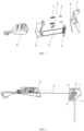
Fig. 1 is an exploded view of the present invention. -
Fig. 2 is a schematic view of the use state of a top tether strap of the present invention in a forward travelling mode. -
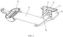
Fig. 3 is a schematic view of the use state of the top tether strap of the present invention in a reverse travelling mode. - The present invention will be described in further detail below with reference to the drawings and specific embodiments. Referring to
Fig. 1 , an intelligent top tether strap structure comprises a fixing member 1, aswitch 2, aguide member 3, a connectingmember 4, atop tether strap 5, abuckle 6, a firstelastic member 7, a secondelastic member 8, a reminder device and acover plate 9. - One end of the top tether strap is connected to the buckle, the other end passes through the fixing member and is then connected to the connecting member, and the switch is located below the side of the top tether strap that is connected to the connecting member. The fixing member 1 is fittingly connected to a safety seat body. The
switch 2, theguide member 3 and the firstelastic member 7 are all disposed on the fixing member 1. Theswitch 2 is electrically connected to the reminder device. The reminder device can be disposed at any position, provided that the reminder device can implement a reminding function after being disposed. The reminder device is a sounding device or a light-emitting device or other somatosensory reminder devices. - The connecting
member 4 is fittingly connected to theguide member 3, and theguide member 3 has a guiding function to define the movement direction of the connectingmember 4. The firstelastic member 7 cooperates with the connectingmember 4. When the connectingmember 4 is pulled by thetop tether strap 5, the firstelastic member 7 provides a resilient force, such that the connectingmember 4 abuts against theswitch 2 when a force of pulling thetop tether strap 5 reaches a set value or the connecting member moves to a set position. The first elastic member is preferably a spring. - The
cover plate 9 is fittingly connected to the fixing member 1. By configuring the cover plate to fit with the fixing member, the connecting member is protected. - Referring to
Fig. 2 , when the top tether strap adopts a forward travelling mode, the connecting member is connected to the buckle by means of the top tether strap. The top tether strap is pulled, such that the connecting member is moved. When the pulling force reaches a certain extent or the connecting member moves to a set position, the connecting member will contact the switch, and then a reminding message is issued, indicating that the top tether strap has been tightened. - The fixing member 1 is further provided with a second
elastic member 8, and the secondelastic member 8 abuts against and presses the connecting member under an external force. - Referring to
Fig. 3 , when the top tether strap adopts a reverse travelling mode, the pulling force of the top tether strap on the connecting member cannot reach the limit value. Therefore, an additional action of the second elastic member is required to allow the tension force of the top tether strap to reach the limit value. In the case that the top tether strap is tensioned to apply a force to a fixing plate, when the buckle is pulled to allow the top tether strap to be tightened, the second elastic member will be subjected to a certain pressure, and when the pressure reaches the limit value, the second elastic member will be pressed against the connecting member, and may contact the switch after being compressed by a certain travel. - The above embodiments only intend to illustrate but not limit the technical solutions of the present invention. Although the present invention has been described in detail with reference to the foregoing embodiments, those of ordinary skill in the art should understand that the technical solutions cited in the foregoing embodiments may be modified, or some of the technical features are equivalently replaced; as long as the resulting structure belongs to the scope of protection which is defined by the appended claims.
Claims (6)
- A top tether strap structure, comprising:a fixing member (1) fittingly connectable to a safety seat body;a connecting member (4), a top tether strap (5) and a buckle (6), wherein one end of the top tether strap is connected to the buckle, and the other end passes through the fixing member and is then connected to the connecting member;characterized in that it further comprises:a switch (2) disposed on the fixing member, wherein when the buckle pulls the top tether strap to allow the connecting member to move to a set position, the connecting member abuts against the switch; anda reminder device electrically connected to the switch.
- The top tether strap structure according to claim 1, characterized in that the fixing member (1) is provided with a first elastic member (7) for cooperating with the connecting member (4), and when a force of pulling the top tether strap (5) reaches a set value, the connecting member abuts against the switch (2).
- The top tether strap structure according to claim 1 or 2, characterized in that the fixing member (1) is provided with a guide member (3), and the connecting member (4) is fittingly connected to the guide member.
- The top tether strap structure according to claim 3, characterized in that the fixing member (1) is further provided with a second elastic member (8), and the second elastic member abuts against and presses the connecting member (4) under an external force.
- The top tether strap structure according to claim 4, characterized in that the reminder device is a sounding device.
- The top tether strap structure according to claim 5, characterized in that the fixing member is further fittingly provided with a cover plate.
Applications Claiming Priority (2)
| Application Number | Priority Date | Filing Date | Title |
|---|---|---|---|
| CN201820141676.6U CN207931541U (en) | 2018-01-29 | 2018-01-29 | Pulling belt structure in a kind of intelligence |
| PCT/CN2018/121351 WO2019144729A1 (en) | 2018-01-29 | 2018-12-15 | Intelligent top tether strap structure |
Publications (4)
| Publication Number | Publication Date |
|---|---|
| EP3702207A1 EP3702207A1 (en) | 2020-09-02 |
| EP3702207A4 EP3702207A4 (en) | 2021-07-21 |
| EP3702207B1 true EP3702207B1 (en) | 2025-02-05 |
| EP3702207C0 EP3702207C0 (en) | 2025-02-05 |
Family
ID=63650283
Family Applications (1)
| Application Number | Title | Priority Date | Filing Date |
|---|---|---|---|
| EP18902106.6A Active EP3702207B1 (en) | 2018-01-29 | 2018-12-15 | Top tether strap structure |
Country Status (3)
| Country | Link |
|---|---|
| EP (1) | EP3702207B1 (en) |
| CN (1) | CN207931541U (en) |
| WO (1) | WO2019144729A1 (en) |
Families Citing this family (1)
| Publication number | Priority date | Publication date | Assignee | Title |
|---|---|---|---|---|
| CN207931541U (en) * | 2018-01-29 | 2018-10-02 | 麦克英孚(宁波)婴童用品有限公司 | Pulling belt structure in a kind of intelligence |
Citations (1)
| Publication number | Priority date | Publication date | Assignee | Title |
|---|---|---|---|---|
| FR2946582A1 (en) * | 2009-06-12 | 2010-12-17 | Dorel France Sa | CHILDREN'S CAR SEAT FOR EQUIPPING A VEHICLE SEAT. |
Family Cites Families (8)
| Publication number | Priority date | Publication date | Assignee | Title |
|---|---|---|---|---|
| FR2853285B1 (en) * | 2003-04-02 | 2006-04-28 | Ampafrance | DEVICE FOR CONNECTING A CHILD SEAT IN A MOTOR VEHICLE WITH A VOLTAGE INDICATOR AND CORRESPONDING CHILD SEAT |
| WO2006009619A2 (en) * | 2004-06-07 | 2006-01-26 | Delphi Technologies, Inc | Child restraint system comprising weight sensor |
| US8235463B2 (en) * | 2010-02-05 | 2012-08-07 | Ford Global Technologies, Llc | Child seat tethering system |
| CN203698007U (en) * | 2013-12-28 | 2014-07-09 | 麦克英孚(宁波)婴童用品有限公司 | Regulator for vehicle child safety seat |
| CN204978307U (en) * | 2015-08-28 | 2016-01-20 | 麦克英孚(宁波)婴童用品有限公司 | Installation detection device on children's safety seat |
| CN205553968U (en) * | 2016-03-15 | 2016-09-07 | 好孩子儿童用品有限公司 | Safety belt constraint induction system and children vehicle security seat chair |
| CN206067562U (en) * | 2016-09-29 | 2017-04-05 | 珠海弘点科技有限公司 | Motor vehicles child passenger safety seat |
| CN207931541U (en) * | 2018-01-29 | 2018-10-02 | 麦克英孚(宁波)婴童用品有限公司 | Pulling belt structure in a kind of intelligence |
-
2018
- 2018-01-29 CN CN201820141676.6U patent/CN207931541U/en active Active
- 2018-12-15 EP EP18902106.6A patent/EP3702207B1/en active Active
- 2018-12-15 WO PCT/CN2018/121351 patent/WO2019144729A1/en not_active Ceased
Patent Citations (1)
| Publication number | Priority date | Publication date | Assignee | Title |
|---|---|---|---|---|
| FR2946582A1 (en) * | 2009-06-12 | 2010-12-17 | Dorel France Sa | CHILDREN'S CAR SEAT FOR EQUIPPING A VEHICLE SEAT. |
Also Published As
| Publication number | Publication date |
|---|---|
| EP3702207A4 (en) | 2021-07-21 |
| WO2019144729A1 (en) | 2019-08-01 |
| EP3702207A1 (en) | 2020-09-02 |
| CN207931541U (en) | 2018-10-02 |
| EP3702207C0 (en) | 2025-02-05 |
Similar Documents
| Publication | Publication Date | Title |
|---|---|---|
| US20040011277A1 (en) | Seat belt tension sensing device | |
| CN112829647B (en) | Child Safety Seat Alarm Device | |
| CN112208405B (en) | Automobile safety seat for children | |
| US20100301594A1 (en) | Guide Assembly for a Safety Belt | |
| WO2006044559A3 (en) | Harness adjustment mechanism for achild vehicle seat | |
| GB0225890D0 (en) | Two-stage protective car seat cover for child and infant safety chairs | |
| TWI772970B (en) | Child safety seat alarm system and child safety seat | |
| CN208393303U (en) | A kind of elastic intelligent regulator of ribbon and the children car seat using it | |
| EP3702207A1 (en) | Intelligent top tether strap structure | |
| CN112208403B (en) | Automobile child seat | |
| CN205553968U (en) | Safety belt constraint induction system and children vehicle security seat chair | |
| CN205273407U (en) | Safety belt uses detection device | |
| CN114802096A (en) | B-surface type safety belt reminding sensor device based on micro switch | |
| US20100007186A1 (en) | Tension indicator | |
| ATE275058T1 (en) | CONNECTING ELEMENT FOR CHILD SAFETY SEAT | |
| US4345238A (en) | Signalling device for use in automotive and like vehicles | |
| CN218661468U (en) | Safety warning device of upper drawstring connected with belt buckle | |
| CN218316363U (en) | Safety warning device of upper pull belt | |
| CN215883402U (en) | Alarm system of safety seat and safety seat | |
| CN201597555U (en) | Reminding device for reminding people of correctly wearing automobile safety belts | |
| EP1692480B1 (en) | Tension indicator | |
| CN203438977U (en) | Comfort degree regulator for automobile safety belt | |
| CN202574126U (en) | On-board alarming device | |
| CN113306523A (en) | Children's safety seat and taut suggestion device of baldric thereof | |
| CN223735887U (en) | Child steam seat headrest connecting structure and child steam seat |
Legal Events
| Date | Code | Title | Description |
|---|---|---|---|
| STAA | Information on the status of an ep patent application or granted ep patent |
Free format text: STATUS: THE INTERNATIONAL PUBLICATION HAS BEEN MADE |
|
| PUAI | Public reference made under article 153(3) epc to a published international application that has entered the european phase |
Free format text: ORIGINAL CODE: 0009012 |
|
| STAA | Information on the status of an ep patent application or granted ep patent |
Free format text: STATUS: REQUEST FOR EXAMINATION WAS MADE |
|
| 17P | Request for examination filed |
Effective date: 20200528 |
|
| AK | Designated contracting states |
Kind code of ref document: A1 Designated state(s): AL AT BE BG CH CY CZ DE DK EE ES FI FR GB GR HR HU IE IS IT LI LT LU LV MC MK MT NL NO PL PT RO RS SE SI SK SM TR |
|
| AX | Request for extension of the european patent |
Extension state: BA ME |
|
| DAV | Request for validation of the european patent (deleted) | ||
| DAX | Request for extension of the european patent (deleted) | ||
| A4 | Supplementary search report drawn up and despatched |
Effective date: 20210616 |
|
| RIC1 | Information provided on ipc code assigned before grant |
Ipc: B60N 2/28 20060101AFI20210611BHEP |
|
| STAA | Information on the status of an ep patent application or granted ep patent |
Free format text: STATUS: EXAMINATION IS IN PROGRESS |
|
| 17Q | First examination report despatched |
Effective date: 20220301 |
|
| REG | Reference to a national code |
Ref country code: DE Ref legal event code: R079 Free format text: PREVIOUS MAIN CLASS: B60N0002280000 Ipc: B60N0002260000 Ref country code: DE Ref legal event code: R079 Ref document number: 602018079000 Country of ref document: DE Free format text: PREVIOUS MAIN CLASS: B60N0002280000 Ipc: B60N0002260000 |
|
| GRAP | Despatch of communication of intention to grant a patent |
Free format text: ORIGINAL CODE: EPIDOSNIGR1 |
|
| STAA | Information on the status of an ep patent application or granted ep patent |
Free format text: STATUS: GRANT OF PATENT IS INTENDED |
|
| RIC1 | Information provided on ipc code assigned before grant |
Ipc: B60N 2/28 20060101ALI20241004BHEP Ipc: B60N 2/26 20060101AFI20241004BHEP |
|
| INTG | Intention to grant announced |
Effective date: 20241017 |
|
| GRAS | Grant fee paid |
Free format text: ORIGINAL CODE: EPIDOSNIGR3 |
|
| GRAA | (expected) grant |
Free format text: ORIGINAL CODE: 0009210 |
|
| STAA | Information on the status of an ep patent application or granted ep patent |
Free format text: STATUS: THE PATENT HAS BEEN GRANTED |
|
| AK | Designated contracting states |
Kind code of ref document: B1 Designated state(s): AL AT BE BG CH CY CZ DE DK EE ES FI FR GB GR HR HU IE IS IT LI LT LU LV MC MK MT NL NO PL PT RO RS SE SI SK SM TR |
|
| REG | Reference to a national code |
Ref country code: GB Ref legal event code: FG4D |
|
| REG | Reference to a national code |
Ref country code: CH Ref legal event code: EP |
|
| REG | Reference to a national code |
Ref country code: DE Ref legal event code: R096 Ref document number: 602018079000 Country of ref document: DE |
|
| REG | Reference to a national code |
Ref country code: IE Ref legal event code: FG4D |
|
| U01 | Request for unitary effect filed |
Effective date: 20250224 |
|
| U07 | Unitary effect registered |
Designated state(s): AT BE BG DE DK EE FI FR IT LT LU LV MT NL PT RO SE SI Effective date: 20250303 |
|
| PG25 | Lapsed in a contracting state [announced via postgrant information from national office to epo] |
Ref country code: RS Free format text: LAPSE BECAUSE OF FAILURE TO SUBMIT A TRANSLATION OF THE DESCRIPTION OR TO PAY THE FEE WITHIN THE PRESCRIBED TIME-LIMIT Effective date: 20250505 |
|
| PG25 | Lapsed in a contracting state [announced via postgrant information from national office to epo] |
Ref country code: PL Free format text: LAPSE BECAUSE OF FAILURE TO SUBMIT A TRANSLATION OF THE DESCRIPTION OR TO PAY THE FEE WITHIN THE PRESCRIBED TIME-LIMIT Effective date: 20250205 |
|
| PG25 | Lapsed in a contracting state [announced via postgrant information from national office to epo] |
Ref country code: ES Free format text: LAPSE BECAUSE OF FAILURE TO SUBMIT A TRANSLATION OF THE DESCRIPTION OR TO PAY THE FEE WITHIN THE PRESCRIBED TIME-LIMIT Effective date: 20250205 |
|
| PG25 | Lapsed in a contracting state [announced via postgrant information from national office to epo] |
Ref country code: IS Free format text: LAPSE BECAUSE OF FAILURE TO SUBMIT A TRANSLATION OF THE DESCRIPTION OR TO PAY THE FEE WITHIN THE PRESCRIBED TIME-LIMIT Effective date: 20250605 Ref country code: NO Free format text: LAPSE BECAUSE OF FAILURE TO SUBMIT A TRANSLATION OF THE DESCRIPTION OR TO PAY THE FEE WITHIN THE PRESCRIBED TIME-LIMIT Effective date: 20250505 |
|
| PG25 | Lapsed in a contracting state [announced via postgrant information from national office to epo] |
Ref country code: HR Free format text: LAPSE BECAUSE OF FAILURE TO SUBMIT A TRANSLATION OF THE DESCRIPTION OR TO PAY THE FEE WITHIN THE PRESCRIBED TIME-LIMIT Effective date: 20250205 |
|
| PG25 | Lapsed in a contracting state [announced via postgrant information from national office to epo] |
Ref country code: GR Free format text: LAPSE BECAUSE OF FAILURE TO SUBMIT A TRANSLATION OF THE DESCRIPTION OR TO PAY THE FEE WITHIN THE PRESCRIBED TIME-LIMIT Effective date: 20250506 |
|
| PG25 | Lapsed in a contracting state [announced via postgrant information from national office to epo] |
Ref country code: SM Free format text: LAPSE BECAUSE OF FAILURE TO SUBMIT A TRANSLATION OF THE DESCRIPTION OR TO PAY THE FEE WITHIN THE PRESCRIBED TIME-LIMIT Effective date: 20250205 |
|
| PG25 | Lapsed in a contracting state [announced via postgrant information from national office to epo] |
Ref country code: CZ Free format text: LAPSE BECAUSE OF FAILURE TO SUBMIT A TRANSLATION OF THE DESCRIPTION OR TO PAY THE FEE WITHIN THE PRESCRIBED TIME-LIMIT Effective date: 20250205 |
|
| PG25 | Lapsed in a contracting state [announced via postgrant information from national office to epo] |
Ref country code: SK Free format text: LAPSE BECAUSE OF FAILURE TO SUBMIT A TRANSLATION OF THE DESCRIPTION OR TO PAY THE FEE WITHIN THE PRESCRIBED TIME-LIMIT Effective date: 20250205 |
|
| U1N | Appointed representative for the unitary patent procedure changed after the registration of the unitary effect |
Representative=s name: SANTARELLI; FR |
|
| PLBE | No opposition filed within time limit |
Free format text: ORIGINAL CODE: 0009261 |
|
| STAA | Information on the status of an ep patent application or granted ep patent |
Free format text: STATUS: NO OPPOSITION FILED WITHIN TIME LIMIT |
|
| PGFP | Annual fee paid to national office [announced via postgrant information from national office to epo] |
Ref country code: GB Payment date: 20251224 Year of fee payment: 8 |
|
| 26N | No opposition filed |
Effective date: 20251106 |
|
| U20 | Renewal fee for the european patent with unitary effect paid |
Year of fee payment: 8 Effective date: 20251223 |