EP3702194A1 - Head-up display device and mounting structure for head-up display device - Google Patents
Head-up display device and mounting structure for head-up display device Download PDFInfo
- Publication number
- EP3702194A1 EP3702194A1 EP20159111.2A EP20159111A EP3702194A1 EP 3702194 A1 EP3702194 A1 EP 3702194A1 EP 20159111 A EP20159111 A EP 20159111A EP 3702194 A1 EP3702194 A1 EP 3702194A1
- Authority
- EP
- European Patent Office
- Prior art keywords
- vehicle
- head
- display device
- down direction
- concave mirror
- Prior art date
- Legal status (The legal status is an assumption and is not a legal conclusion. Google has not performed a legal analysis and makes no representation as to the accuracy of the status listed.)
- Granted
Links
Images



Classifications
-
- G—PHYSICS
- G02—OPTICS
- G02B—OPTICAL ELEMENTS, SYSTEMS OR APPARATUS
- G02B27/00—Optical systems or apparatus not provided for by any of the groups G02B1/00 - G02B26/00, G02B30/00
- G02B27/01—Head-up displays
- G02B27/0149—Head-up displays characterised by mechanical features
-
- B—PERFORMING OPERATIONS; TRANSPORTING
- B60—VEHICLES IN GENERAL
- B60K—ARRANGEMENT OR MOUNTING OF PROPULSION UNITS OR OF TRANSMISSIONS IN VEHICLES; ARRANGEMENT OR MOUNTING OF PLURAL DIVERSE PRIME-MOVERS IN VEHICLES; AUXILIARY DRIVES FOR VEHICLES; INSTRUMENTATION OR DASHBOARDS FOR VEHICLES; ARRANGEMENTS IN CONNECTION WITH COOLING, AIR INTAKE, GAS EXHAUST OR FUEL SUPPLY OF PROPULSION UNITS IN VEHICLES
- B60K35/00—Instruments specially adapted for vehicles; Arrangement of instruments in or on vehicles
- B60K35/10—Input arrangements, i.e. from user to vehicle, associated with vehicle functions or specially adapted therefor
-
- B—PERFORMING OPERATIONS; TRANSPORTING
- B60—VEHICLES IN GENERAL
- B60K—ARRANGEMENT OR MOUNTING OF PROPULSION UNITS OR OF TRANSMISSIONS IN VEHICLES; ARRANGEMENT OR MOUNTING OF PLURAL DIVERSE PRIME-MOVERS IN VEHICLES; AUXILIARY DRIVES FOR VEHICLES; INSTRUMENTATION OR DASHBOARDS FOR VEHICLES; ARRANGEMENTS IN CONNECTION WITH COOLING, AIR INTAKE, GAS EXHAUST OR FUEL SUPPLY OF PROPULSION UNITS IN VEHICLES
- B60K35/00—Instruments specially adapted for vehicles; Arrangement of instruments in or on vehicles
- B60K35/20—Output arrangements, i.e. from vehicle to user, associated with vehicle functions or specially adapted therefor
- B60K35/21—Output arrangements, i.e. from vehicle to user, associated with vehicle functions or specially adapted therefor using visual output, e.g. blinking lights or matrix displays
- B60K35/23—Head-up displays [HUD]
-
- B—PERFORMING OPERATIONS; TRANSPORTING
- B60—VEHICLES IN GENERAL
- B60K—ARRANGEMENT OR MOUNTING OF PROPULSION UNITS OR OF TRANSMISSIONS IN VEHICLES; ARRANGEMENT OR MOUNTING OF PLURAL DIVERSE PRIME-MOVERS IN VEHICLES; AUXILIARY DRIVES FOR VEHICLES; INSTRUMENTATION OR DASHBOARDS FOR VEHICLES; ARRANGEMENTS IN CONNECTION WITH COOLING, AIR INTAKE, GAS EXHAUST OR FUEL SUPPLY OF PROPULSION UNITS IN VEHICLES
- B60K35/00—Instruments specially adapted for vehicles; Arrangement of instruments in or on vehicles
- B60K35/50—Instruments characterised by their means of attachment to or integration in the vehicle
-
- B—PERFORMING OPERATIONS; TRANSPORTING
- B60—VEHICLES IN GENERAL
- B60K—ARRANGEMENT OR MOUNTING OF PROPULSION UNITS OR OF TRANSMISSIONS IN VEHICLES; ARRANGEMENT OR MOUNTING OF PLURAL DIVERSE PRIME-MOVERS IN VEHICLES; AUXILIARY DRIVES FOR VEHICLES; INSTRUMENTATION OR DASHBOARDS FOR VEHICLES; ARRANGEMENTS IN CONNECTION WITH COOLING, AIR INTAKE, GAS EXHAUST OR FUEL SUPPLY OF PROPULSION UNITS IN VEHICLES
- B60K37/00—Dashboards
- B60K37/20—Dashboard panels
-
- B—PERFORMING OPERATIONS; TRANSPORTING
- B62—LAND VEHICLES FOR TRAVELLING OTHERWISE THAN ON RAILS
- B62D—MOTOR VEHICLES; TRAILERS
- B62D25/00—Superstructure or monocoque structure sub-units; Parts or details thereof not otherwise provided for
- B62D25/08—Front or rear portions
- B62D25/081—Cowls
-
- B—PERFORMING OPERATIONS; TRANSPORTING
- B60—VEHICLES IN GENERAL
- B60K—ARRANGEMENT OR MOUNTING OF PROPULSION UNITS OR OF TRANSMISSIONS IN VEHICLES; ARRANGEMENT OR MOUNTING OF PLURAL DIVERSE PRIME-MOVERS IN VEHICLES; AUXILIARY DRIVES FOR VEHICLES; INSTRUMENTATION OR DASHBOARDS FOR VEHICLES; ARRANGEMENTS IN CONNECTION WITH COOLING, AIR INTAKE, GAS EXHAUST OR FUEL SUPPLY OF PROPULSION UNITS IN VEHICLES
- B60K2360/00—Indexing scheme associated with groups B60K35/00 or B60K37/00 relating to details of instruments or dashboards
- B60K2360/60—Structural details of dashboards or instruments
- B60K2360/68—Features of instruments
- B60K2360/691—Housings
-
- B—PERFORMING OPERATIONS; TRANSPORTING
- B60—VEHICLES IN GENERAL
- B60K—ARRANGEMENT OR MOUNTING OF PROPULSION UNITS OR OF TRANSMISSIONS IN VEHICLES; ARRANGEMENT OR MOUNTING OF PLURAL DIVERSE PRIME-MOVERS IN VEHICLES; AUXILIARY DRIVES FOR VEHICLES; INSTRUMENTATION OR DASHBOARDS FOR VEHICLES; ARRANGEMENTS IN CONNECTION WITH COOLING, AIR INTAKE, GAS EXHAUST OR FUEL SUPPLY OF PROPULSION UNITS IN VEHICLES
- B60K2360/00—Indexing scheme associated with groups B60K35/00 or B60K37/00 relating to details of instruments or dashboards
- B60K2360/816—Fastening of displays or touch screens
-
- B—PERFORMING OPERATIONS; TRANSPORTING
- B60—VEHICLES IN GENERAL
- B60K—ARRANGEMENT OR MOUNTING OF PROPULSION UNITS OR OF TRANSMISSIONS IN VEHICLES; ARRANGEMENT OR MOUNTING OF PLURAL DIVERSE PRIME-MOVERS IN VEHICLES; AUXILIARY DRIVES FOR VEHICLES; INSTRUMENTATION OR DASHBOARDS FOR VEHICLES; ARRANGEMENTS IN CONNECTION WITH COOLING, AIR INTAKE, GAS EXHAUST OR FUEL SUPPLY OF PROPULSION UNITS IN VEHICLES
- B60K2360/00—Indexing scheme associated with groups B60K35/00 or B60K37/00 relating to details of instruments or dashboards
- B60K2360/84—Mounting of dashboard components
-
- G—PHYSICS
- G02—OPTICS
- G02B—OPTICAL ELEMENTS, SYSTEMS OR APPARATUS
- G02B27/00—Optical systems or apparatus not provided for by any of the groups G02B1/00 - G02B26/00, G02B30/00
- G02B27/01—Head-up displays
- G02B27/0101—Head-up displays characterised by optical features
- G02B2027/0118—Head-up displays characterised by optical features comprising devices for improving the contrast of the display / brillance control visibility
- G02B2027/012—Head-up displays characterised by optical features comprising devices for improving the contrast of the display / brillance control visibility comprising devices for attenuating parasitic image effects
-
- G—PHYSICS
- G02—OPTICS
- G02B—OPTICAL ELEMENTS, SYSTEMS OR APPARATUS
- G02B27/00—Optical systems or apparatus not provided for by any of the groups G02B1/00 - G02B26/00, G02B30/00
- G02B27/01—Head-up displays
- G02B27/0101—Head-up displays characterised by optical features
Definitions
- the invention relates to a head-up display device and a mounting structure for a head-up display device.
- JP 2010-064709 A describes a technique regarding a head-up display device in which a fixing member is provided that protrudes from a lower part of a side wall of a housing (hereinafter referred to as "casing") and that is connected to a bracket provided on a vehicle body.
- the fixing member includes a support portion supported by the bracket, a fastening portion fastened to the bracket, and a connecting portion that connects the support portion and the side wall of the casing.
- the connecting portion is provided with a groove and a bottom side of the groove serves as a thin portion.
- the thin portion is configured to be broken when a predetermined external force is applied to the casing, and the connection between the casing and the bracket is released with the breakage of the thin portion.
- the head-up display device moves downward in a vehicle up-down direction.
- a front windshield and the like move downward in the vehicle up-down direction, which enables absorption of an impact energy.
- JP 2014-156219 A describes a technique regarding a head-up display device in which a plurality of fragile portions with a smaller thickness (hereinafter referred to as "thin portions") are provided in corners, steps, and the like of a lower case constituting a lower part of a casing.
- thin portions a plurality of fragile portions with a smaller thickness
- the thin portions are broken and the casing is crushed so that an impact energy can be absorbed.
- the thin portions are provided in the fixing member supporting the casing of the head-up display device or in the lower case of the head-up display device.
- the thin portions by causing the thin portions to be broken, it is possible to absorb the impact energy.
- a light source unit that emits image information is disposed at a lower part (in the lower case) of the head-up display device. Therefore, when the thin portions are provided to make the fixing member for the head-up display or the lower case of the head-up display device fragile as described above, the image information emitted from the light source unit may jitter due to vibration of the vehicle during traveling, such as road surface input.
- the invention provides a head-up display device and a mounting structure for a head-up display device that suppress jitters of image information during traveling of a vehicle and can absorb an impact energy when an impact load is input from above the vehicle.
- a first aspect of the invention relates to a head-up display device.
- the head-up display device includes a casing provided inside an instrument panel and provided with a concave mirror configured to project image information emitted from a light source onto a front windshield glass.
- a retraction portion is provided on a lower side of the concave mirror in a vehicle up-down direction and configured to allow the concave mirror to move downward in the vehicle up-down direction when an impact load is input to the concave mirror from an upper side in the vehicle up-down direction.
- the casing of the head-up display device is provided inside the instrument panel, and the casing is provided with the concave mirror that projects the image information emitted from the light source onto the front windshield glass.
- the concave mirror is held as it is and does not move downward in the vehicle up-down direction when the impact load is input to the concave mirror from the upper side in the vehicle up-down direction.
- deformation of the casing of the head-up display device is suppressed by a reaction force of the concave mirror.
- the retraction portion that allows the concave mirror to move downward in the vehicle up-down direction is provided on the lower side of the concave mirror in the vehicle up-down direction.
- the front windshield glass, the instrument panel, and the like can be deformed downward in the vehicle up-down direction without being intercepted by the concave mirror.
- the concave mirror downward in the vehicle up-down direction by moving the concave mirror downward in the vehicle up-down direction to sufficiently deform the front windshield glass, the instrument panel, and the like, it is possible to effectively absorb the impact energy.
- the head-up display device configured such that the casing is broken at a fragile portion to absorb the impact energy
- the front windshield glass, the instrument panel, and the like are deformed to absorb energy in the above aspect. Accordingly, in the above aspect, it is possible to secure rigidity of the casing itself of the head-up display device. As a result, in the above aspect, the head-up display device can suppress jitters of the image information during traveling of the vehicle.
- the head-up display device can suppress jitters of the image information during traveling of the vehicle and absorb the impact energy when the impact load is input from the upper side in the vehicle up-down direction.
- the casing may include an upper case constituting an upper part of the casing and a lower case constituting a lower part of the casing.
- the retraction portion may be provided at a position including an opening that is provided in a lower wall of the lower case.
- the casing of the head-up display device includes the upper case constituting the upper part of the casing and the lower case constituting the lower part of the casing.
- the retraction portion that allows the concave mirror to move downward in the vehicle up-down direction includes the opening provided in the lower wall of the lower case.
- the casing of the head-up display device is deformed when the impact load is input from the upper side in the vehicle up-down direction. That is, the casing is crushed (deformed) from the upper part side toward the lower part side.
- the concave mirror attempts to move downward in the vehicle up-down direction with the deformation of the casing. Since the concave mirror moves downward in the vehicle up-down direction through the opening provided in the lower wall of the lower case, the casing can be deformed without being intercepted by the concave mirror.
- the head-up display device of the above configuration provides an excellent effect that the concave mirror can be moved downward in the vehicle up-down direction through the opening provided in the lower case so as to deform the casing.
- the casing may further include a first wall constituting a part of the lower case and extending along the vehicle up-down direction, a second wall constituting a part of the upper case, extending along the vehicle up-down direction, and overlapping the first wall from outside, and a connecting tool connecting an upper end of the first wall in the vehicle up-down direction and a lower end of the second wall in the vehicle up-down direction and configured to be broken when the impact load is input to the casing from the upper side in the vehicle up-down direction.
- the first wall constituting a part of the lower case is formed to extend along the vehicle up-down direction.
- the second wall constituting a part of the upper case is formed to extend along the vehicle up-down direction, and is arranged so as to overlap the first wall of the lower case from outside.
- the upper end of the first wall of the lower case in the vehicle up-down direction and the lower end of the second wall of the upper case in the vehicle up-down direction are connected with each other with the connecting tool.
- the connecting tool is configured to be broken when the impact load is input to the casing of the head-up display device from the upper side in the vehicle up-down direction.
- the second wall of the upper case is disposed so as to overlap the first wall of the lower case from outside, and the connecting tool connects the upper end of the first wall of the lower case with the lower end of the second wall of the upper case.
- the front windshield glass, the instrument panel, and the like are deformed to absorb the impact energy when the impact load is input from the upper side in the vehicle up-down direction, in the above aspect. That is, in the above aspect, the rigidity of the casing itself of the head-up display device can be secured.
- a rib may protrude downward in the vehicle up-down direction from an inner edge of the opening.
- the rib protrudes downward in the vehicle up-down direction from the inner edge of the opening, so that the rigidity around the opening is improved. Thereby, it is possible to suppress the deformation of the opening due to the deformation of the casing.
- the head-up display device of the above configuration provides an excellent effect that the deformation of the opening is suppressed and the concave mirror can be moved downward in the vehicle up-down direction through the opening.
- the concave mirror may be provided in the lower case.
- the concave mirror may have a shape that bulges in a convex shape toward a front of a vehicle in a plan view of the vehicle. At least a front part of the opening in the vehicle front-rear direction may have a curved shape that bulges in a convex shape toward the front of the vehicle in the plan view of the vehicle.
- the lower case may have higher rigidity than the upper case.
- a second aspect of the invention relates to a mounting structure for a head-up display device.
- the mounting structure includes: a head-up display device including a casing that is provided inside an instrument panel and is provided with a concave mirror configured to project image information emitted from a light source onto a front windshield glass; and a cowl panel extending along a vehicle width direction at a front part of the front windshield glass in a vehicle front-rear direction, and covering a front part of the head-up display device in the vehicle front-rear direction from outside the head-up display device.
- a lower wall of the casing of the head-up display device is provided with an opening that allows the concave mirror to move downward in a vehicle up-down direction when an impact load is input to the concave mirror from an upper side in the vehicle up-down direction.
- the cowl panel includes a facing wall constituting a part of the cowl panel, disposed below the lower wall in the vehicle up-down direction, and disposed such that a retraction space is secured between the facing wall and the lower wall, the retraction space allowing the concave mirror that has passed through the opening to move downward in the vehicle up-down direction.
- the head-up display device is provided inside the instrument panel.
- the casing of the head-up display device is provided with the concave mirror that projects the image information emitted from the light source onto the front windshield glass.
- the cowl panel extends along the vehicle width direction and covers, from outside, the front part of the head-up display device in the vehicle front-rear direction.
- the lower wall of the casing of the head-up display device is provided with the opening.
- the opening allows the concave mirror to move downward in the vehicle up-down direction when the impact load is input to the concave mirror from the upper side in the vehicle up-down direction.
- the facing wall constituting a part of the cowl panel and provided below the lower wall of the casing of the head-up display device in the vehicle up-down direction secures, between the lower wall of the casing and the facing wall, the retraction space that allows the concave mirror that has passed through the opening to move downward in the vehicle up-down direction. That is, in the above aspect, the retraction space that allows the concave mirror that has passed through the opening to move downward in the vehicle up-down direction is provided between the lower wall of the casing of the head-up display device and the facing wall of the cowl panel.
- the concave mirror 80 can accordingly move further downward in the vehicle up-down direction, compared to the case where the retraction space is not provided.
- the amounts of downward deformation of the front windshield glass, the instrument panel, the cowl panel, and the like in the vehicle up-down direction increase, thereby increasing the amount of impact energy to be absorbed accordingly.
- the mounting structure of the second aspect provides an excellent effect that jitters of the image information during traveling of the vehicle can be suppressed and the impact energy can be absorbed when the impact load is input from the upper side in the vehicle up-down direction.
- the facing wall may include a deflection face configured to convert a downward movement of the concave mirror in the vehicle up-down direction into a rearward movement in the vehicle front-rear direction.
- the facing wall of the cowl panel is provided with the deflection face.
- the deflection face is configured to convert the downward movement of the concave mirror in the vehicle up-down direction into the rearward movement in the vehicle front-rear direction.
- the facing wall of the cowl panel is provided below the lower wall of the casing of the head-up display device in the vehicle up-down direction, and as described above, the retraction space is provided between the lower wall of the casing and the facing wall of the cowl panel.
- the facing wall of the cowl panel is provided with the deflection face, and the deflection face is configured to convert the downward movement of the concave mirror in the vehicle up-down direction into the rearward movement in the vehicle front-rear direction.
- the front windshield glass, the instrument panel, the cowl panel, and the like can be effectively deformed downward in the vehicle up-down direction with the retraction space having a minimum necessary length in the vehicle up-down direction.
- a first cowl reinforcement and a second cowl reinforcement may be attached to the cowl panel, with the head-up display device interposed between the first cowl reinforcement and the second cowl reinforcement, on a rear side of the cowl panel in the vehicle front-rear direction.
- the head-up display device may include a first fixing portion that is fixed to the first cowl reinforcement and a second fixing portion that is fixed to the second cowl reinforcement.
- an arrow FR appropriately shown in the drawings indicates a front side in a vehicle front-rear direction
- an arrow UP indicates an upper side in a vehicle up-down direction
- An arrow OUT indicates an outer side in a vehicle width direction.
- FIG. 1 is a sectional view of a front part 14A of a cabin 14 of the vehicle 10, taken along the vehicle up-down direction and the vehicle front-rear direction. As shown in FIG. 1 , an instrument panel 16 is provided at the front part 14A of the cabin 14 of the vehicle 10.
- the instrument panel 16 is attached to a generally columnar instrument panel reinforcement extending between front pillars provided at both ends of the vehicle 10 in the vehicle width direction, and covers a steering column, etc. from an upper side in the vehicle up-down direction.
- a front windshield glass 18 is provided above the instrument panel 16.
- the front windshield glass 18 is supported by a cowl 20 provided forward of the instrument panel 16 so as to extend along substantially the entire region of the vehicle width, upper portions of the front pillars disposed at both ends of the vehicle 10 in the vehicle width direction, and a front header panel (not shown) provided on the upper side of the front pillars so as to extend along the vehicle width direction.
- the cowl 20 includes a cowl panel 22 made of a steel sheet.
- the cowl panel 22 covers a front part 12A of the head-up display device 12 from an outside of the head-up display device 12 and constitutes a rear part 20A of the cowl 20.
- the cowl panel 22 is welded (connected) to an upper end 28A of a dash panel 28 via a bracket 24 etc. having a crank shape in a side view of the vehicle.
- the dash panel 28 is made of a steel sheet, extends in both the vehicle up-down direction and the vehicle width direction, and separates a power unit room 26 accommodating a power unit of the vehicle 10 from the cabin 14.
- a front part 20B of the cowl 20 is provided with a cowl panel 32 that form, together with the cowl panel 22, a closed section 30 in the side view of the vehicle.
- the "closed section 30" need not necessarily have a completely closed section structure.
- the cowl panel 32 includes a cowl upper panel 34 that constitutes an upper part of the cowl panel 32 and is made from resin and a cowl lower panel 36 that constitutes a lower part of the cowl panel 32 and is made of metal, for example.
- the cowl upper panel 34 forms a part of a cowl louver 38 provided on the front side of the front windshield glass 18 in the vehicle front-rear direction.
- the cowl panel 22 is formed so as to cover the front part 12A of the head-up display device 12 from the outside of the head-up display device 12 as described above.
- the cowl panel 22 is formed so as to face an upper wall 40, a side wall 42, and a lower wall 44 of the head-up display device 12, and has a generally C shape with its rear part in the vehicle front-rear direction opened in the side view of the vehicle.
- the upper part 22A of the cowl panel 22 is provided with a support portion 46 that faces the upper wall 40 of the head-up display device 12 and supports a lower end 18A of the front windshield glass 18 from a lower side in the vehicle up-down direction.
- the support portion 46 is provided with a joint portion 47 that joins the front windshield glass 18 to the cowl panel 22.
- bent portions 48, 50 are provided so as to be arranged side by side in an up-down direction of the cowl panel 22.
- the bent portions 48, 50 face the side wall 42 of the head-up display device 12 and are bent toward the front of the vehicle.
- the cowl panel 22 can be bent toward the front of the vehicle with the bent portions 48, 50 serving as starting points.
- the cowl panel 22 is provided with the bent portions 48, 50 and is bent with the bent portions 48, 50 serving as the starting points, so that an impact energy can be effectively absorbed with deformation of the cowl panel 22.
- a lower part 22C of the cowl panel 22 is provided with a facing wall 52 facing the lower wall 44 of the head-up display device 12.
- the facing wall 52 is tilted downward in the vehicle up-down direction as extending toward a rear of the vehicle.
- a retraction space 54 constituting a part of a retraction portion 53 is provided between the facing wall 52 and the lower wall 44 of the head-up display device 12 described later.
- a deflection face 56 is provided at a rear part 52A of the facing wall 52.
- the deflection face 56 is formed so as to be tilted at a gentler angle with respect to a horizontal plane compared to a front part 52B of the facing wall 52.
- a lower part 24A of the bracket 24 described above is fastened to a rear end of the facing wall 52 of the cowl panel 22.
- An upper part 24B of the bracket 24 is welded to the upper end 28A of the dash panel 28.
- the lower wall 44 of the head-up display device 12 is provided with a step 71 in order to avoid interference with the upper part 24B of the bracket 24 and the upper end 28A of the dash panel 28.
- the step 71 is not necessarily required.
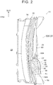
- FIG. 2 shows a plan view of the front part 14A of the cabin 14 of the vehicle 10, with the instrument panel 16 and the front windshield glass 18 shown in FIG. 1 omitted.
- the vehicle 10 is a so-called left-hand drive vehicle, but may be a right-hand drive vehicle.
- cowl reinforcements 58, 60 are provided on the rear side of the cowl panel 22 in the vehicle front-rear direction, while being separated from each other in the vehicle width direction with the head-up display device 12 interposed therebetween.
- the head-up display device 12 is fixed to first ends 58A, 60A of the cowl reinforcements 58, 60 in a longitudinal direction thereof via fixing portions 70C, 70D (see FIG. 3 ) described later and is fastened to the dash panel 28 via a bracket 73.
- FIG. 3 shows a plan view of the head-up display device 12. Configuration of Head-Up Display Device
- the head-up display device 12 shown in FIG. 1 is configured such that vehicle information (hereinafter referred to as "image information”) is emitted as an image from a light source unit (light source) 62 composed of LEDs and the like, and the image information is displayed as a virtual image on the front windshield glass 18 through a transmission glass 64 provided in the upper wall 40 of the head-up display device 12 and an opening 16A of the instrument panel 16.
- image information vehicle information
- a light source unit (light source) 62 composed of LEDs and the like
- the image information is displayed as a virtual image on the front windshield glass 18 through a transmission glass 64 provided in the upper wall 40 of the head-up display device 12 and an opening 16A of the instrument panel 16.
- a casing 66 of the head-up display device 12 includes an upper case 68 constituting an upper part 66A of the casing 66 and a lower case 70 constituting a lower part 66B of the casing 66.
- Each of the upper case 68 and the lower case 70 has a generally rectangular shape in a plan view, which is long in the vehicle width direction, and is made from resin.
- the upper case 68 includes a lid portion 68A (right side in the drawing) constituting the upper wall 40 (left side in the drawing) of the head-up display device 12, and a wall (second wall) 68B (right side in the drawing) extending downward from an outer edge of the lid portion 68A and constituting the side wall 42 (left side in the drawing) of the head-up display device 12.
- the lower case 70 includes a bottom wall 70A (right side in the drawing) constituting the lower wall 44 (left side in the drawing) of the head-up display device 12 and a wall (first wall) 70B extending upward from an outer edge of the bottom wall 70A.
- the upper wall 40 of the head-up display device 12 and the lid portion 68A of the upper case 68 indicate the same part, and the side wall 42 of the head-up display device 12 and the wall 68B of the upper case 68 indicate the same part, although described with different reference characters and designations for convenience of explanation. Similarly, the lower wall 44 of the head-up display device 12 and the bottom wall 70A of the lower case 70 also indicate the same part.
- an outer dimension of the upper case 68 is set to be slightly larger than that of the lower case 70.
- the upper case 68 can be connected to the lower case 70 such that the wall 68B of the upper case 68 overlaps the wall 70B of the lower case 70 from outside.
- a connecting piece (lower end of the wall 68B in the vehicle up-down direction) 72 extends downward from a lower edge of the wall 68B of the upper case 68.
- the connecting piece 72 overlaps, from outside, an upper end 70B 1 of the wall 70B of the lower case 70 in the vehicle up-down direction.
- the upper case 68 is fixed to the lower case 70 via screws (connecting tools) 74 with connecting holes formed in the connecting piece 72 and connecting holes formed in the wall 70B of the lower case 70 aligned with each other.
- the screws 74 are configured to be broken by a shearing force when an impact load F is input to the head-up display device 12 from the upper side in the vehicle up-down direction along a long dashed short dashed line P with the upper case 68 fixed to the lower case 70 via the screws 74.
- the impact load F is set based on, for example, the Pedestrian Head Protection Performance Tests defined in the Japan New Car Assessment Program (JNCAP). That is, a load that acts on (is input to) the front windshield glass 18 when a head impactor 76, which is a collision body simulating the head of an adult or child, is projected from a testing machine to collide with the front windshield glass 18 is defined as the impact load F.
- JNCAP Japan New Car Assessment Program
- the lower case 70 of the head-up display device 12 is provided with at least the light source unit 62, a flat mirror 78, and a concave mirror 80.
- the light source unit 62 and the flat mirror 78 are accommodated in an accommodating portion 82 provided in the lower case 70.
- the concave mirror 80 is disposed at the front part 12A of the head-up display device 12 and below the support portion 46 in a vehicle up-down direction that passes through the support portion 46 supporting the front windshield glass 18 and that extends along a load input direction (long dashed short dashed line P) of the head impactor 76.
- FIG. 4 shows a bottom view of the head-up display device 12.
- the accommodating portion 82 of the head-up display device 12 is provided with a plurality of vent holes 84 configured to release heat in the accommodating portion 82.
- the vent holes 84 are closed by a sheet or the like (not shown) that can dissipate heat and suppress entry of dust and the like.
- the accommodating portion 82 is closed by a cover 86 so that dust does not enter the accommodating portion 82, as shown in FIG. 1 .
- the cover 86 is provided with a transmission glass 87 so as to transmit light.
- the light (image information) emitted from the light source unit 62 is refracted by the flat mirror 78, passes through the transmission glass 87, and is incident on the concave mirror 80 by a reflection mirror or the like (not shown).
- the concave mirror 80 is made of highly transparent resin such as polycarbonate (PC) or glass.
- the light (image information) projected by the concave mirror 80 is transmitted toward the front windshield glass 18 as described above, and a virtual image is formed on the front windshield glass 18.
- the lower case 70 of the head-up display device 12 is provided with the light source unit 62 that emits image information.
- a plate thickness, a material, and the like of the lower case 70 are set so as to obtain high rigidity in consideration of an influence of vibration and the like.
- the upper case 68 is formed to have lower rigidity than the lower case 70.
- the upper case 68 is formed so as to have a smaller plate thickness than the lower case 70, or is formed of a material having a Young's modulus lower than that of the material of the lower case 70.
- the upper case 68 may be formed so as to satisfy both of these.
- the upper case 68 and the lower case 70 are made from resin, but not limited to this.
- the upper case 68 and the lower case 70 may be made of metal.
- the lower case 70 may be made of metal, and the upper case 68 may be made from resin.
- the bottom wall 70A of the lower case 70 of the head-up display device 12 is provided with an opening 88 on the lower side of the concave mirror 80 in the vehicle up-down direction.
- the opening 88 constitutes another part of the retraction portion 53 and has a rectangular shape that is long in the vehicle width direction.
- a rib 88A protrudes downward in the vehicle up-down direction from an inner edge of the opening 88.
- the concave mirror 80 has a shape that bulges in a convex shape toward the front of the vehicle in a substantially plan view. Therefore, a curved portion 88B is provided at a front part of the opening 88 in the vehicle front-rear direction. The curved portion 88B bulges in a convex shape toward the front of the vehicle in the substantially plan view so as to conform with the shape of the concave mirror 80, as shown in FIG. 4 . This enables the concave mirror 80 to pass through the opening 88 with a minimum necessary size.
- the lower case 70 of the head-up display device 12 is provided with the fixing portions 70C, 70D.
- the fixing portion 70C is fixed to the cowl reinforcement 58 (see FIG. 2 ) and the fixing portion 70D is fixed to the cowl reinforcement 60 (see FIG. 2 ), via fastening members such as bolts.
- a first end 73A of the long plate-shaped bracket 73 in its longitudinal direction is fixed to the lower case 70 of the head-up display device 12.
- a second end 73B of the bracket 73 in its longitudinal direction is fixed to the dash panel 28 (see FIG. 2 ).
- the head-up display device 12 is fixed to (supported by) the cowl reinforcements 58, 60 and the dash panel 28 shown in FIG. 2 .
- the method of supporting the head-up display device 12 is not limited to this.
- the head-up display device 12 may be configured to be supported by the instrument panel reinforcement via a bracket or the like.
- the facing wall 52 of the cowl panel 22 is provided below the opening 88 formed in the lower case 70, with the head-up display device 12 provided to an inside 17 of the instrument panel 16 via the lower case 70.
- the retraction space 54 is provided between the bottom wall 70A of the lower case 70 (the lower wall 44 of the head-up display device 12) and the facing wall 52 of the cowl panel 22.
- the head-up display device 12 is provided to the inside 17 of the instrument panel 16.
- the casing 66 of the head-up display device 12 is provided with the concave mirror 80 that projects the image information emitted from the light source unit 62 toward the front windshield glass 18.
- the retraction portion 53 is provided on the lower side of the concave mirror 80 in the vehicle up-down direction.
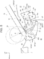
- the retraction portion 53 is provided to allow the concave mirror 80 to move downward in the vehicle up-down direction when the impact load F (see FIG. 5 ) is input to the head-up display device 12 from above the vehicle via the front windshield glass 18.
- the impact load F is input from above the vehicle to the head-up display device 12, but the concave mirror 80 is held as it is and does not move downward in the vehicle up-down direction.
- deformation of the casing 66 of the head-up display device 12 is suppressed by a reaction force of the concave mirror 80.
- the deformation of the casing 66 of the head-up display device 12 is suppressed, the downward movement (deformation) of the front windshield glass 18, the instrument panel 16, the cowl panel 22, and the like in the vehicle up-down direction is also suppressed. Therefore, in the comparative example, there is a possibility that the impact energy cannot be sufficiently absorbed when the impact load F is input to the front windshield glass 18 from above the vehicle.
- the retraction portion 53 that allows the concave mirror 80 to move downward in the vehicle up-down direction is provided on the lower side of the concave mirror 80 in the vehicle up-down direction, as described above.
- the concave mirror 80 can move downward in the vehicle up-down direction.
- FIG. 5 is an operation diagram showing the front part 14A of the cabin 14 of the vehicle 10 before and after the impact load F is input, taken along the vehicle up-down direction and the vehicle front-rear direction.
- Long dashed double-short dashed lines indicate a state before the input of the impact load F
- solid lines indicate a state after the input of the impact load F.
- the front windshield glass 18, the instrument panel 16, the cowl panel 22, and the like can be deformed downward in the vehicle up-down direction without being intercepted by the concave mirror 80.
- the concave mirror 80 by moving the concave mirror 80 downward in the vehicle up-down direction to sufficiently deform the front windshield glass 18, the instrument panel 16, the cowl panel 22, and the like, it is possible to effectively absorb the impact energy.
- the head-up display device 12 can suppress jitters of the image information during traveling of the vehicle 10.
- the head-up display device 12 can suppress jitters of the image information during traveling of the vehicle 10, and can absorb the impact energy when the impact load F is input from the upper side in the vehicle up-down direction.
- the absorption of the impact energy it is possible to reduce the reaction force to the pedestrian, thereby reducing the impact acting on the pedestrian.
- the casing 66 of the head-up display device 12 can realize two contradictory performances, i.e., higher rigidity for suppressing jitters of the image information and lower rigidity for protecting pedestrians.
- the casing 66 of the head-up display device 12 includes the upper case 68 constituting the upper part of the casing 66 and the lower case 70 constituting the lower part of the casing 66, and the retraction portion 53 includes the opening 88 formed in the bottom wall 70A of the lower case 70.
- the concave mirror 80 can pass through the opening 88 formed in the lower case 70 when the casing 66 is deformed and the concave mirror 80 moves downward in the vehicle up-down direction.
- the concave mirror 80 attempts to move downward in the vehicle up-down direction with the deformation of the casing 66.
- the concave mirror 80 moves downward in the vehicle up-down direction through the opening 88 formed in the bottom wall 70A of the lower case 70, so that the casing 66 can be deformed without being intercepted by the concave mirror 80.
- the rib 88A protrudes downward in the vehicle up-down direction from the inner edge of the opening 88. Therefore, the rigidity around the opening 88 is improved. Therefore, the deformation of the opening 88 due to the deformation of the casing 66 can be suppressed.
- the concave mirror 80 can be guided toward the cowl panel 22 along the rib 88A when passing through the opening 88.
- the rib 88A is not necessarily required.
- the outer dimension of the upper case 68 of the head-up display device 12 is set to be slightly larger than the outer dimension of the lower case 70.
- the connecting piece 72 extending downward from the wall 68B of the upper case 68 is connected to the lower case 70 so as to overlap, from outside, the upper end 70B1 of the wall 70B of the lower case 70.
- the screws 74 that connect the upper case 68 and the lower case 70 are configured to be broken by a shearing force when the impact load F is input to the casing 66 of the head-up display device 12 from above the vehicle.
- the wall 68B of the upper case 68 is disposed so as to overlap the wall 70B of the lower case 70 from outside to be connected thereto by the screws 74.
- the upper case 68 moves toward the lower case 70 (downward in the vehicle up-down direction).
- the concave mirror 80 moves downward in the vehicle up-down direction.
- the screws 74 that connect the lower case 70 and the upper case 68 are broken to reduce the volume of the casing 66, so that the amounts of deformation (deformation strokes) of the front windshield glass 18, the instrument panel 16, the cowl panel 22, and the like are increased, thereby increasing the amount of impact energy to be absorbed.
- the head-up display device is configured such that the casing is broken at the fragile portion to absorb impact energy
- the front windshield glass 18, the instrument panel 16, the cowl panel 22, and the like are deformed to absorb the impact energy in the present embodiment.
- the rigidity of the casing 66 itself of the head-up display device 12 can be secured.
- the cowl 20 extends along the vehicle width direction at the front part of the front windshield glass 18 in the vehicle front-rear direction, and the cowl 20 covers the front part 12A of the head-up display device 12 from outside.
- the bottom wall 70A of the lower case 70 of the head-up display device 12 is provided with the opening 88 constituting a part of the retraction portion 53.
- the opening 88 allows the concave mirror 80 to move downward in the vehicle up-down direction when the impact load F is input to the concave mirror 80 from above the vehicle.
- the retraction space 54 constituting another part of the retraction portion 53 is secured between the facing wall 52 and the bottom wall 70A of the lower case 70.
- the facing wall 52 constitutes a part of the cowl 20 and is provided below the bottom wall 70A of the lower case 70.
- the retraction portion 53 allows the concave mirror 80 that has passed through the opening 88 to move downward in the vehicle up-down direction.
- the retraction space 54 that allows the concave mirror 80 that has passed through the opening 88 to move downward in the vehicle up-down direction is provided between the bottom wall 70A of the lower case 70 and the facing wall 52 of the cowl 20.
- the concave mirror 80 can accordingly move further downward in the vehicle up-down direction, compared to the case where the retraction space 54 is not provided (not shown).
- the amounts of downward deformation of the front windshield glass 18, the instrument panel 16, the cowl panel 22, and the like in the vehicle up-down direction increase, thereby increasing the amount of impact energy to be absorbed accordingly.
- the facing wall 52 of the cowl 20 is provided with the deflection face 56.
- the deflection face 56 is configured to convert the downward movement of the concave mirror 80 in the vehicle up-down direction into a rearward movement in the vehicle front-rear direction.
- the facing wall 52 of the cowl 20 is provided below the bottom wall 70A of the lower case 70 in the vehicle up-down direction.
- the retraction space 54 is provided between the bottom wall 70A of the lower case 70 and the facing wall 52 of the cowl 20.
- the facing wall 52 of the cowl 20 is provided with the deflection face 56, so that the downward movement of the concave mirror 80 in the vehicle up-down direction is converted into the rearward movement in the vehicle front-rear direction.
- the front windshield glass 18, the instrument panel 16, the cowl panel 22, and the like can be effectively deformed downward in the vehicle up-down direction, with the retraction space 54 having a minimum necessary length in the vehicle up-down direction.
- the deflection face 56 is not necessarily required.
- the opening 88 is provided in the bottom wall 70A of the lower case 70 as the retraction portion 53, as shown in FIG. 1 .
- the invention is not limited to this, as long as the downward movement of the concave mirror 80 in the vehicle up-down direction is not intercepted when the impact load F is input from above the vehicle.
- the opening 88 is not necessarily an opening, and may be closed by a member having a lower strength than the lower case 70, such as a tape, a thin plate, etc. in order to suppress entry of dust or the like.
- a member having a lower strength than the lower case 70 such as a tape, a thin plate, etc. in order to suppress entry of dust or the like.
- the opening 88 need not necessarily be provided in the bottom wall 70A of the lower case 70 as the retraction portion 53.
- the bottom wall 70A of the lower case 70 may be provided with a recess that protrudes downward in the vehicle up-down direction and allows the concave mirror 80 to move downward in the vehicle up-down direction.
- the upper case 68 includes the lid portion 68A and the wall 68B
- the lower case 70 includes the bottom wall 70A and the wall 70B.
- the upper case 68 only needs to be movable downward in the vehicle up-down direction with respect to the lower case 70, so its shape, configuration, and the like are not limited to the above.
- the wall 70B is not necessarily required.
- the upper case 68 is fixed to the lower case 70 via the screws 74 serving as the connecting tools.
- the connecting tools are configured to be broken when the impact load F is input to the head-up display device 12, so the screws 74 need not necessarily be adopted.
- clips or the like that come off with breakage may be used instead of the screws 74.
- the connecting tools are not limited to those described above.
- the wall 68B of the upper case 68 may be provided with claw portions.
- the claw portions are engaged with the wall 70B of the lower case 70 and are broken when the impact load F is input.
Landscapes
- Engineering & Computer Science (AREA)
- Chemical & Material Sciences (AREA)
- Combustion & Propulsion (AREA)
- Transportation (AREA)
- Mechanical Engineering (AREA)
- Physics & Mathematics (AREA)
- General Physics & Mathematics (AREA)
- Optics & Photonics (AREA)
- Instrument Panels (AREA)
Abstract
Description
- The invention relates to a head-up display device and a mounting structure for a head-up display device.
- Japanese Unexamined Patent Application Publication No.
2010-064709 JP 2010-064709 A - The thin portion is configured to be broken when a predetermined external force is applied to the casing, and the connection between the casing and the bracket is released with the breakage of the thin portion. Thus, when the thin portion is broken, the head-up display device moves downward in a vehicle up-down direction. Thereby, a front windshield and the like move downward in the vehicle up-down direction, which enables absorption of an impact energy.
- Japanese Unexamined Patent Application Publication No.
2014-156219 JP 2014-156219 A - As described above, in the related art, the thin portions are provided in the fixing member supporting the casing of the head-up display device or in the lower case of the head-up display device. Thus, by causing the thin portions to be broken, it is possible to absorb the impact energy.
- In general, a light source unit that emits image information is disposed at a lower part (in the lower case) of the head-up display device. Therefore, when the thin portions are provided to make the fixing member for the head-up display or the lower case of the head-up display device fragile as described above, the image information emitted from the light source unit may jitter due to vibration of the vehicle during traveling, such as road surface input.
- The invention provides a head-up display device and a mounting structure for a head-up display device that suppress jitters of image information during traveling of a vehicle and can absorb an impact energy when an impact load is input from above the vehicle.
- A first aspect of the invention relates to a head-up display device. The head-up display device includes a casing provided inside an instrument panel and provided with a concave mirror configured to project image information emitted from a light source onto a front windshield glass. In the head-up display device, a retraction portion is provided on a lower side of the concave mirror in a vehicle up-down direction and configured to allow the concave mirror to move downward in the vehicle up-down direction when an impact load is input to the concave mirror from an upper side in the vehicle up-down direction.
- In the head-up display device of the above aspect, the casing of the head-up display device is provided inside the instrument panel, and the casing is provided with the concave mirror that projects the image information emitted from the light source onto the front windshield glass.
- Suppose, as a comparative example, the concave mirror is held as it is and does not move downward in the vehicle up-down direction when the impact load is input to the concave mirror from the upper side in the vehicle up-down direction. In this case, deformation of the casing of the head-up display device is suppressed by a reaction force of the concave mirror.
- When the deformation of the casing is suppressed as in the comparative example, downward movement (deformation) of the front windshield glass, the instrument panel, and the like in the vehicle up-down direction is also suppressed. Thus, in the head-up display device of the comparative example, there is a possibility that an impact energy cannot be absorbed sufficiently when the impact load is input from the upper side in the vehicle up-down direction.
- In contrast, in the above aspect, the retraction portion that allows the concave mirror to move downward in the vehicle up-down direction is provided on the lower side of the concave mirror in the vehicle up-down direction. Thereby, when the impact load is input to the concave mirror from the upper side in the vehicle up-down direction, the concave mirror can move downward in the vehicle up-down direction.
- That is, in the above aspect, the front windshield glass, the instrument panel, and the like can be deformed downward in the vehicle up-down direction without being intercepted by the concave mirror. Thus, in the above aspect, by moving the concave mirror downward in the vehicle up-down direction to sufficiently deform the front windshield glass, the instrument panel, and the like, it is possible to effectively absorb the impact energy.
- Thus, unlike the head-up display device configured such that the casing is broken at a fragile portion to absorb the impact energy, the front windshield glass, the instrument panel, and the like are deformed to absorb energy in the above aspect. Accordingly, in the above aspect, it is possible to secure rigidity of the casing itself of the head-up display device. As a result, in the above aspect, the head-up display device can suppress jitters of the image information during traveling of the vehicle.
- Thus, in the above aspect, the head-up display device can suppress jitters of the image information during traveling of the vehicle and absorb the impact energy when the impact load is input from the upper side in the vehicle up-down direction.
- In the head-up display device according to the above aspect, the casing may include an upper case constituting an upper part of the casing and a lower case constituting a lower part of the casing. The retraction portion may be provided at a position including an opening that is provided in a lower wall of the lower case.
- In the head-up display device of the above aspect, the casing of the head-up display device includes the upper case constituting the upper part of the casing and the lower case constituting the lower part of the casing. The retraction portion that allows the concave mirror to move downward in the vehicle up-down direction includes the opening provided in the lower wall of the lower case. Thus, by providing the opening in the lower wall of the lower case, the concave mirror can pass through the opening when the casing is deformed and the concave mirror moves downward in the vehicle up-down direction.
- Here, the casing of the head-up display device is deformed when the impact load is input from the upper side in the vehicle up-down direction. That is, the casing is crushed (deformed) from the upper part side toward the lower part side. At this time, the concave mirror attempts to move downward in the vehicle up-down direction with the deformation of the casing. Since the concave mirror moves downward in the vehicle up-down direction through the opening provided in the lower wall of the lower case, the casing can be deformed without being intercepted by the concave mirror.
- That is, the head-up display device of the above configuration provides an excellent effect that the concave mirror can be moved downward in the vehicle up-down direction through the opening provided in the lower case so as to deform the casing.
- In the head-up display device according to the above aspect, the casing may further include a first wall constituting a part of the lower case and extending along the vehicle up-down direction, a second wall constituting a part of the upper case, extending along the vehicle up-down direction, and overlapping the first wall from outside, and a connecting tool connecting an upper end of the first wall in the vehicle up-down direction and a lower end of the second wall in the vehicle up-down direction and configured to be broken when the impact load is input to the casing from the upper side in the vehicle up-down direction.
- In the head-up display device of the above aspect, the first wall constituting a part of the lower case is formed to extend along the vehicle up-down direction. The second wall constituting a part of the upper case is formed to extend along the vehicle up-down direction, and is arranged so as to overlap the first wall of the lower case from outside. The upper end of the first wall of the lower case in the vehicle up-down direction and the lower end of the second wall of the upper case in the vehicle up-down direction are connected with each other with the connecting tool.
- Here, the connecting tool is configured to be broken when the impact load is input to the casing of the head-up display device from the upper side in the vehicle up-down direction. As described above, the second wall of the upper case is disposed so as to overlap the first wall of the lower case from outside, and the connecting tool connects the upper end of the first wall of the lower case with the lower end of the second wall of the upper case. Thus, when the connecting tool is broken, the upper case moves toward the lower case (downward in the vehicle up-down direction). As a result, the concave mirror moves downward in the vehicle up-down direction.
- That is, in the above aspect, a configuration is adopted in which the lower case and the upper case are overlapped and connected in a shear direction with respect to the input load, and the connecting tool is broken. Therefore, the volume of the casing can be reduced. As a result, the amounts of deformation (deformation strokes) of the front windshield glass, the instrument panel, and the like are increased, thereby increasing the amount of impact energy to be absorbed.
- Thus, unlike the head-up display device configured such that the casing is broken at the fragile portion to absorb the impact energy, the front windshield glass, the instrument panel, and the like are deformed to absorb the impact energy when the impact load is input from the upper side in the vehicle up-down direction, in the above aspect. That is, in the above aspect, the rigidity of the casing itself of the head-up display device can be secured.
- In the head-up display device according to the above aspect, a rib may protrude downward in the vehicle up-down direction from an inner edge of the opening.
- In the head-up display device of the above aspect, the rib protrudes downward in the vehicle up-down direction from the inner edge of the opening, so that the rigidity around the opening is improved. Thereby, it is possible to suppress the deformation of the opening due to the deformation of the casing.
- That is, the head-up display device of the above configuration provides an excellent effect that the deformation of the opening is suppressed and the concave mirror can be moved downward in the vehicle up-down direction through the opening.
- In the head-up display device according to the above aspect, the concave mirror may be provided in the lower case.
- In the head-up display device according to the above aspect, the concave mirror may have a shape that bulges in a convex shape toward a front of a vehicle in a plan view of the vehicle. At least a front part of the opening in the vehicle front-rear direction may have a curved shape that bulges in a convex shape toward the front of the vehicle in the plan view of the vehicle.
- In the head-up display device according to the above aspect, the lower case may have higher rigidity than the upper case.
- A second aspect of the invention relates to a mounting structure for a head-up display device. The mounting structure includes: a head-up display device including a casing that is provided inside an instrument panel and is provided with a concave mirror configured to project image information emitted from a light source onto a front windshield glass; and a cowl panel extending along a vehicle width direction at a front part of the front windshield glass in a vehicle front-rear direction, and covering a front part of the head-up display device in the vehicle front-rear direction from outside the head-up display device. In the mounting structure, a lower wall of the casing of the head-up display device is provided with an opening that allows the concave mirror to move downward in a vehicle up-down direction when an impact load is input to the concave mirror from an upper side in the vehicle up-down direction. The cowl panel includes a facing wall constituting a part of the cowl panel, disposed below the lower wall in the vehicle up-down direction, and disposed such that a retraction space is secured between the facing wall and the lower wall, the retraction space allowing the concave mirror that has passed through the opening to move downward in the vehicle up-down direction.
- In the mounting structure of the above aspect, the head-up display device is provided inside the instrument panel. The casing of the head-up display device is provided with the concave mirror that projects the image information emitted from the light source onto the front windshield glass.
- Meanwhile, at the front part of the front windshield glass in the vehicle front-rear direction, the cowl panel extends along the vehicle width direction and covers, from outside, the front part of the head-up display device in the vehicle front-rear direction.
- Here, in the above aspect, the lower wall of the casing of the head-up display device is provided with the opening. The opening allows the concave mirror to move downward in the vehicle up-down direction when the impact load is input to the concave mirror from the upper side in the vehicle up-down direction. The facing wall constituting a part of the cowl panel and provided below the lower wall of the casing of the head-up display device in the vehicle up-down direction secures, between the lower wall of the casing and the facing wall, the retraction space that allows the concave mirror that has passed through the opening to move downward in the vehicle up-down direction. That is, in the above aspect, the retraction space that allows the concave mirror that has passed through the opening to move downward in the vehicle up-down direction is provided between the lower wall of the casing of the head-up display device and the facing wall of the cowl panel.
- Thus, since the retraction space is provided between the lower wall of the casing of the head-up display device and the facing wall of the cowl panel, the
concave mirror 80 can accordingly move further downward in the vehicle up-down direction, compared to the case where the retraction space is not provided. As a result, the amounts of downward deformation of the front windshield glass, the instrument panel, the cowl panel, and the like in the vehicle up-down direction increase, thereby increasing the amount of impact energy to be absorbed accordingly. - As described above, the mounting structure of the second aspect provides an excellent effect that jitters of the image information during traveling of the vehicle can be suppressed and the impact energy can be absorbed when the impact load is input from the upper side in the vehicle up-down direction.
- In the mounting structure according to the above aspect, the facing wall may include a deflection face configured to convert a downward movement of the concave mirror in the vehicle up-down direction into a rearward movement in the vehicle front-rear direction.
- In the mounting structure of the above aspect, the facing wall of the cowl panel is provided with the deflection face. The deflection face is configured to convert the downward movement of the concave mirror in the vehicle up-down direction into the rearward movement in the vehicle front-rear direction. The facing wall of the cowl panel is provided below the lower wall of the casing of the head-up display device in the vehicle up-down direction, and as described above, the retraction space is provided between the lower wall of the casing and the facing wall of the cowl panel.
- Here, in order to increase the amounts of downward deformation of the front windshield glass, the instrument panel, the cowl panel, and the like in the vehicle up-down direction, it is only necessary to set the retraction space to be large. In other words, it is only necessary to largely separate the lower wall of the casing and the facing wall of the cowl panel. In this case, however, the size of the cowl panel increases and the weight of the vehicle increases accordingly.
- In contrast, in the above aspect, the facing wall of the cowl panel is provided with the deflection face, and the deflection face is configured to convert the downward movement of the concave mirror in the vehicle up-down direction into the rearward movement in the vehicle front-rear direction. As a result, the front windshield glass, the instrument panel, the cowl panel, and the like can be effectively deformed downward in the vehicle up-down direction with the retraction space having a minimum necessary length in the vehicle up-down direction.
- In the mounting structure according to the above aspect, a first cowl reinforcement and a second cowl reinforcement may be attached to the cowl panel, with the head-up display device interposed between the first cowl reinforcement and the second cowl reinforcement, on a rear side of the cowl panel in the vehicle front-rear direction. The head-up display device may include a first fixing portion that is fixed to the first cowl reinforcement and a second fixing portion that is fixed to the second cowl reinforcement.
- Features, advantages, and technical and industrial significance of exemplary embodiments of the invention will be described below with reference to the accompanying drawings, in which like numerals denote like elements, and wherein:
-
FIG. 1 is a sectional view of a front part of a cabin of a vehicle on which a head-up display device according to an embodiment is mounted, taken along a vehicle up-down direction and a vehicle front-rear direction; -
FIG. 2 is a plan view of the front part of the cabin of the vehicle on which the head-up display device according to the embodiment is mounted; -
FIG. 3 is a plan view of the head-up display device according to the embodiment; -
FIG. 4 is a bottom view of the head-up display device according to the embodiment; and -
FIG. 5 is an operation diagram showing the front part of the cabin of the vehicle, on which the head-up display device according to the embodiment is mounted, before and after the impact load is input, taken along the vehicle up-down direction and the vehicle front-rear direction. - Hereinafter, a head-up display device according to an embodiment of the invention will be described with reference to the drawings. Note that an arrow FR appropriately shown in the drawings indicates a front side in a vehicle front-rear direction, and an arrow UP indicates an upper side in a vehicle up-down direction. An arrow OUT indicates an outer side in a vehicle width direction.
- First, a
vehicle 10 on which a head-updisplay device 12 is mounted will be described.FIG. 1 is a sectional view of afront part 14A of acabin 14 of thevehicle 10, taken along the vehicle up-down direction and the vehicle front-rear direction. As shown inFIG. 1 , aninstrument panel 16 is provided at thefront part 14A of thecabin 14 of thevehicle 10. - Although not shown, the
instrument panel 16 is attached to a generally columnar instrument panel reinforcement extending between front pillars provided at both ends of thevehicle 10 in the vehicle width direction, and covers a steering column, etc. from an upper side in the vehicle up-down direction. - A
front windshield glass 18 is provided above theinstrument panel 16. Thefront windshield glass 18 is supported by acowl 20 provided forward of theinstrument panel 16 so as to extend along substantially the entire region of the vehicle width, upper portions of the front pillars disposed at both ends of thevehicle 10 in the vehicle width direction, and a front header panel (not shown) provided on the upper side of the front pillars so as to extend along the vehicle width direction. - Here, for example, the
cowl 20 includes acowl panel 22 made of a steel sheet. Thecowl panel 22 covers afront part 12A of the head-updisplay device 12 from an outside of the head-updisplay device 12 and constitutes arear part 20A of thecowl 20. Thecowl panel 22 is welded (connected) to anupper end 28A of adash panel 28 via abracket 24 etc. having a crank shape in a side view of the vehicle. Thedash panel 28 is made of a steel sheet, extends in both the vehicle up-down direction and the vehicle width direction, and separates apower unit room 26 accommodating a power unit of thevehicle 10 from thecabin 14. - Further, a
front part 20B of thecowl 20 is provided with acowl panel 32 that form, together with thecowl panel 22, aclosed section 30 in the side view of the vehicle. Here, the "closed section 30" need not necessarily have a completely closed section structure. - The
cowl panel 32 includes a cowlupper panel 34 that constitutes an upper part of thecowl panel 32 and is made from resin and a cowllower panel 36 that constitutes a lower part of thecowl panel 32 and is made of metal, for example. The cowlupper panel 34 forms a part of acowl louver 38 provided on the front side of thefront windshield glass 18 in the vehicle front-rear direction. - The
cowl panel 22 is formed so as to cover thefront part 12A of the head-updisplay device 12 from the outside of the head-updisplay device 12 as described above. Thus, thecowl panel 22 is formed so as to face anupper wall 40, aside wall 42, and alower wall 44 of the head-updisplay device 12, and has a generally C shape with its rear part in the vehicle front-rear direction opened in the side view of the vehicle. - Specifically, the
upper part 22A of thecowl panel 22 is provided with asupport portion 46 that faces theupper wall 40 of the head-updisplay device 12 and supports alower end 18A of thefront windshield glass 18 from a lower side in the vehicle up-down direction. Thesupport portion 46 is provided with ajoint portion 47 that joins thefront windshield glass 18 to thecowl panel 22. - Further, at a
center part 22B of thecowl panel 22 in the vehicle up-down direction,bent portions cowl panel 22. Thebent portions side wall 42 of the head-updisplay device 12 and are bent toward the front of the vehicle. Thecowl panel 22 can be bent toward the front of the vehicle with thebent portions cowl panel 22 is provided with thebent portions bent portions cowl panel 22. - A
lower part 22C of thecowl panel 22 is provided with a facingwall 52 facing thelower wall 44 of the head-updisplay device 12. The facingwall 52 is tilted downward in the vehicle up-down direction as extending toward a rear of the vehicle. Aretraction space 54 constituting a part of aretraction portion 53 is provided between the facingwall 52 and thelower wall 44 of the head-updisplay device 12 described later. In addition, at arear part 52A of the facingwall 52, adeflection face 56 is provided. The deflection face 56 is formed so as to be tilted at a gentler angle with respect to a horizontal plane compared to afront part 52B of the facingwall 52. - A
lower part 24A of thebracket 24 described above is fastened to a rear end of the facingwall 52 of thecowl panel 22. Anupper part 24B of thebracket 24 is welded to theupper end 28A of thedash panel 28. Thelower wall 44 of the head-updisplay device 12 is provided with astep 71 in order to avoid interference with theupper part 24B of thebracket 24 and theupper end 28A of thedash panel 28. However, thestep 71 is not necessarily required. -
FIG. 2 shows a plan view of thefront part 14A of thecabin 14 of thevehicle 10, with theinstrument panel 16 and thefront windshield glass 18 shown inFIG. 1 omitted. InFIG. 2 , thevehicle 10 is a so-called left-hand drive vehicle, but may be a right-hand drive vehicle. - Here, as shown in
FIG. 2 ,cowl reinforcements cowl panel 22 in the vehicle front-rear direction, while being separated from each other in the vehicle width direction with the head-updisplay device 12 interposed therebetween. The head-updisplay device 12 is fixed to first ends 58A, 60A of thecowl reinforcements portions FIG. 3 ) described later and is fastened to thedash panel 28 via abracket 73.FIG. 3 shows a plan view of the head-updisplay device 12. Configuration of Head-Up Display Device - Next, the configuration of the head-up
display device 12 will be described. - In brief, the head-up
display device 12 shown inFIG. 1 is configured such that vehicle information (hereinafter referred to as "image information") is emitted as an image from a light source unit (light source) 62 composed of LEDs and the like, and the image information is displayed as a virtual image on thefront windshield glass 18 through atransmission glass 64 provided in theupper wall 40 of the head-updisplay device 12 and anopening 16A of theinstrument panel 16. - A
casing 66 of the head-updisplay device 12 includes anupper case 68 constituting anupper part 66A of thecasing 66 and alower case 70 constituting alower part 66B of thecasing 66. Each of theupper case 68 and thelower case 70 has a generally rectangular shape in a plan view, which is long in the vehicle width direction, and is made from resin. - As shown in
FIG. 1 , theupper case 68 includes alid portion 68A (right side in the drawing) constituting the upper wall 40 (left side in the drawing) of the head-updisplay device 12, and a wall (second wall) 68B (right side in the drawing) extending downward from an outer edge of thelid portion 68A and constituting the side wall 42 (left side in the drawing) of the head-updisplay device 12. Thelower case 70 includes abottom wall 70A (right side in the drawing) constituting the lower wall 44 (left side in the drawing) of the head-updisplay device 12 and a wall (first wall) 70B extending upward from an outer edge of thebottom wall 70A. - The
upper wall 40 of the head-updisplay device 12 and thelid portion 68A of theupper case 68 indicate the same part, and theside wall 42 of the head-updisplay device 12 and thewall 68B of theupper case 68 indicate the same part, although described with different reference characters and designations for convenience of explanation. Similarly, thelower wall 44 of the head-updisplay device 12 and thebottom wall 70A of thelower case 70 also indicate the same part. - Further, in the
casing 66 of the head-updisplay device 12, an outer dimension of theupper case 68 is set to be slightly larger than that of thelower case 70. Theupper case 68 can be connected to thelower case 70 such that thewall 68B of theupper case 68 overlaps thewall 70B of thelower case 70 from outside. - More specifically, in the
casing 66 of the head-updisplay device 12, a connecting piece (lower end of thewall 68B in the vehicle up-down direction) 72 extends downward from a lower edge of thewall 68B of theupper case 68. The connectingpiece 72 overlaps, from outside, anupper end 70B 1 of thewall 70B of thelower case 70 in the vehicle up-down direction. Although not shown, theupper case 68 is fixed to thelower case 70 via screws (connecting tools) 74 with connecting holes formed in the connectingpiece 72 and connecting holes formed in thewall 70B of thelower case 70 aligned with each other. - The
screws 74 are configured to be broken by a shearing force when an impact load F is input to the head-updisplay device 12 from the upper side in the vehicle up-down direction along a long dashed short dashed line P with theupper case 68 fixed to thelower case 70 via thescrews 74. - The impact load F is set based on, for example, the Pedestrian Head Protection Performance Tests defined in the Japan New Car Assessment Program (JNCAP). That is, a load that acts on (is input to) the
front windshield glass 18 when ahead impactor 76, which is a collision body simulating the head of an adult or child, is projected from a testing machine to collide with thefront windshield glass 18 is defined as the impact load F. - The
lower case 70 of the head-updisplay device 12 is provided with at least thelight source unit 62, aflat mirror 78, and aconcave mirror 80. Thelight source unit 62 and theflat mirror 78 are accommodated in anaccommodating portion 82 provided in thelower case 70. Theconcave mirror 80 is disposed at thefront part 12A of the head-updisplay device 12 and below thesupport portion 46 in a vehicle up-down direction that passes through thesupport portion 46 supporting thefront windshield glass 18 and that extends along a load input direction (long dashed short dashed line P) of thehead impactor 76. - Here,
FIG. 4 shows a bottom view of the head-updisplay device 12. As shown inFIGS. 3 and4 , theaccommodating portion 82 of the head-updisplay device 12 is provided with a plurality of vent holes 84 configured to release heat in theaccommodating portion 82. The vent holes 84 are closed by a sheet or the like (not shown) that can dissipate heat and suppress entry of dust and the like. - Further, in the head-up
display device 12, theaccommodating portion 82 is closed by acover 86 so that dust does not enter theaccommodating portion 82, as shown inFIG. 1 . Thecover 86 is provided with atransmission glass 87 so as to transmit light. The light (image information) emitted from thelight source unit 62 is refracted by theflat mirror 78, passes through thetransmission glass 87, and is incident on theconcave mirror 80 by a reflection mirror or the like (not shown). - The
concave mirror 80 is made of highly transparent resin such as polycarbonate (PC) or glass. The light (image information) projected by theconcave mirror 80 is transmitted toward thefront windshield glass 18 as described above, and a virtual image is formed on thefront windshield glass 18. - As described above, the
lower case 70 of the head-updisplay device 12 is provided with thelight source unit 62 that emits image information. Thus, a plate thickness, a material, and the like of thelower case 70 are set so as to obtain high rigidity in consideration of an influence of vibration and the like. Theupper case 68 is formed to have lower rigidity than thelower case 70. - Thus, the
upper case 68 is formed so as to have a smaller plate thickness than thelower case 70, or is formed of a material having a Young's modulus lower than that of the material of thelower case 70. Theupper case 68 may be formed so as to satisfy both of these. In the present embodiment, theupper case 68 and thelower case 70 are made from resin, but not limited to this. Theupper case 68 and thelower case 70 may be made of metal. Furthermore, thelower case 70 may be made of metal, and theupper case 68 may be made from resin. - Further, in the present embodiment, the
bottom wall 70A of thelower case 70 of the head-updisplay device 12 is provided with anopening 88 on the lower side of theconcave mirror 80 in the vehicle up-down direction. Theopening 88 constitutes another part of theretraction portion 53 and has a rectangular shape that is long in the vehicle width direction. Arib 88A protrudes downward in the vehicle up-down direction from an inner edge of theopening 88. - The
concave mirror 80 has a shape that bulges in a convex shape toward the front of the vehicle in a substantially plan view. Therefore, acurved portion 88B is provided at a front part of theopening 88 in the vehicle front-rear direction. Thecurved portion 88B bulges in a convex shape toward the front of the vehicle in the substantially plan view so as to conform with the shape of theconcave mirror 80, as shown inFIG. 4 . This enables theconcave mirror 80 to pass through theopening 88 with a minimum necessary size. - As shown in
FIGS. 3 and4 , thelower case 70 of the head-updisplay device 12 is provided with the fixingportions portions portion 70C is fixed to the cowl reinforcement 58 (seeFIG. 2 ) and the fixingportion 70D is fixed to the cowl reinforcement 60 (seeFIG. 2 ), via fastening members such as bolts. - As shown in
FIG. 4 , afirst end 73A of the long plate-shapedbracket 73 in its longitudinal direction is fixed to thelower case 70 of the head-updisplay device 12. Asecond end 73B of thebracket 73 in its longitudinal direction is fixed to the dash panel 28 (seeFIG. 2 ). - That is, in the present embodiment, the head-up
display device 12 is fixed to (supported by) thecowl reinforcements dash panel 28 shown inFIG. 2 . Note that the method of supporting the head-updisplay device 12 is not limited to this. For example, although not shown, the head-updisplay device 12 may be configured to be supported by the instrument panel reinforcement via a bracket or the like. - In the configuration described above, as shown in
FIG. 1 , the facingwall 52 of thecowl panel 22 is provided below theopening 88 formed in thelower case 70, with the head-updisplay device 12 provided to an inside 17 of theinstrument panel 16 via thelower case 70. Theretraction space 54 is provided between thebottom wall 70A of the lower case 70 (thelower wall 44 of the head-up display device 12) and the facingwall 52 of thecowl panel 22. - Here, operations and effects of the head-up
display device 12 will be described. - As shown in
FIG. 1 , the head-updisplay device 12 is provided to the inside 17 of theinstrument panel 16. Thecasing 66 of the head-updisplay device 12 is provided with theconcave mirror 80 that projects the image information emitted from thelight source unit 62 toward thefront windshield glass 18. - Meanwhile, in the present embodiment, the
retraction portion 53 is provided on the lower side of theconcave mirror 80 in the vehicle up-down direction. Theretraction portion 53 is provided to allow theconcave mirror 80 to move downward in the vehicle up-down direction when the impact load F (seeFIG. 5 ) is input to the head-updisplay device 12 from above the vehicle via thefront windshield glass 18. - Suppose, as a comparative example (not shown), the impact load F is input from above the vehicle to the head-up
display device 12, but theconcave mirror 80 is held as it is and does not move downward in the vehicle up-down direction. In this case, deformation of thecasing 66 of the head-updisplay device 12 is suppressed by a reaction force of theconcave mirror 80. - Thus, if the deformation of the
casing 66 of the head-updisplay device 12 is suppressed, the downward movement (deformation) of thefront windshield glass 18, theinstrument panel 16, thecowl panel 22, and the like in the vehicle up-down direction is also suppressed. Therefore, in the comparative example, there is a possibility that the impact energy cannot be sufficiently absorbed when the impact load F is input to thefront windshield glass 18 from above the vehicle. - In contrast, in the present embodiment shown in
FIG. 1 , theretraction portion 53 that allows theconcave mirror 80 to move downward in the vehicle up-down direction is provided on the lower side of theconcave mirror 80 in the vehicle up-down direction, as described above. Thus, as shown inFIG. 5 , when the impact load F is input to the head-updisplay device 12 from the upper side in the vehicle up-down direction via thefront windshield glass 18, theconcave mirror 80 can move downward in the vehicle up-down direction. -
FIG. 5 is an operation diagram showing thefront part 14A of thecabin 14 of thevehicle 10 before and after the impact load F is input, taken along the vehicle up-down direction and the vehicle front-rear direction. Long dashed double-short dashed lines indicate a state before the input of the impact load F, and solid lines indicate a state after the input of the impact load F. - That is, in the present embodiment, as shown in
FIG. 5 , thefront windshield glass 18, theinstrument panel 16, thecowl panel 22, and the like can be deformed downward in the vehicle up-down direction without being intercepted by theconcave mirror 80. Thus, in the present embodiment, by moving theconcave mirror 80 downward in the vehicle up-down direction to sufficiently deform thefront windshield glass 18, theinstrument panel 16, thecowl panel 22, and the like, it is possible to effectively absorb the impact energy. - Therefore, unlike a comparative example (not shown) in which the head-up display device is configured such that the casing is broken at the fragile portion to absorb impact energy, it is possible to secure the rigidity of the
casing 66 itself of the head-updisplay device 12 in the present embodiment. Therefore, in the present embodiment, the head-updisplay device 12 can suppress jitters of the image information during traveling of thevehicle 10. - Thus, in the present embodiment, the head-up
display device 12 can suppress jitters of the image information during traveling of thevehicle 10, and can absorb the impact energy when the impact load F is input from the upper side in the vehicle up-down direction. Thus, according to the embodiment, with the absorption of the impact energy, it is possible to reduce the reaction force to the pedestrian, thereby reducing the impact acting on the pedestrian. - In particular, when the entire head-up
display device 12 is covered with a metal such as thecowl panel 22 etc., it is difficult to move the entire head-updisplay device 12 downward in the vehicle up-down direction. Thus, with at least theconcave mirror 80 configured to move downward in the vehicle up-down direction, an effect of reducing the impact to the pedestrian's head is expected to be obtained. - In other words, in the present embodiment, the
casing 66 of the head-updisplay device 12 can realize two contradictory performances, i.e., higher rigidity for suppressing jitters of the image information and lower rigidity for protecting pedestrians. - Here, the downward movement of the
concave mirror 80 in the vehicle up-down direction will be specifically described. In the present embodiment, thecasing 66 of the head-updisplay device 12 includes theupper case 68 constituting the upper part of thecasing 66 and thelower case 70 constituting the lower part of thecasing 66, and theretraction portion 53 includes theopening 88 formed in thebottom wall 70A of thelower case 70. Thus, by providing theopening 88 in thebottom wall 70A of thelower case 70, theconcave mirror 80 can pass through theopening 88 formed in thelower case 70 when thecasing 66 is deformed and theconcave mirror 80 moves downward in the vehicle up-down direction. - As shown in
FIG. 5 , when the impact load F is input to the head-updisplay device 12 from above the vehicle via thefront windshield glass 18, thecasing 66 of the head-updisplay device 12 is deformed. That is, thecasing 66 is deformed from the upper part side toward the lower part side. At this time, theconcave mirror 80 attempts to move downward in the vehicle up-down direction with the deformation of thecasing 66. Theconcave mirror 80 moves downward in the vehicle up-down direction through theopening 88 formed in thebottom wall 70A of thelower case 70, so that thecasing 66 can be deformed without being intercepted by theconcave mirror 80. - Furthermore, in the present embodiment, the
rib 88A protrudes downward in the vehicle up-down direction from the inner edge of theopening 88. Thereby, the rigidity around theopening 88 is improved. Therefore, the deformation of theopening 88 due to the deformation of thecasing 66 can be suppressed. - Further, with the
rib 88A protruding downward in the vehicle up-down direction from the inner edge of theopening 88, theconcave mirror 80 can be guided toward thecowl panel 22 along therib 88A when passing through theopening 88. Therib 88A is not necessarily required. - In the present embodiment, the outer dimension of the
upper case 68 of the head-updisplay device 12 is set to be slightly larger than the outer dimension of thelower case 70. The connectingpiece 72 extending downward from thewall 68B of theupper case 68 is connected to thelower case 70 so as to overlap, from outside, the upper end 70B1 of thewall 70B of thelower case 70. Further, thescrews 74 that connect theupper case 68 and thelower case 70 are configured to be broken by a shearing force when the impact load F is input to thecasing 66 of the head-updisplay device 12 from above the vehicle. - As described above, the
wall 68B of theupper case 68 is disposed so as to overlap thewall 70B of thelower case 70 from outside to be connected thereto by thescrews 74. Thus, when thescrews 74 are broken, theupper case 68 moves toward the lower case 70 (downward in the vehicle up-down direction). As a result, theconcave mirror 80 moves downward in the vehicle up-down direction. - That is, in the present embodiment, the
screws 74 that connect thelower case 70 and theupper case 68 are broken to reduce the volume of thecasing 66, so that the amounts of deformation (deformation strokes) of thefront windshield glass 18, theinstrument panel 16, thecowl panel 22, and the like are increased, thereby increasing the amount of impact energy to be absorbed. - Therefore, unlike the comparative example (not shown) in which the head-up display device is configured such that the casing is broken at the fragile portion to absorb impact energy, the
front windshield glass 18, theinstrument panel 16, thecowl panel 22, and the like are deformed to absorb the impact energy in the present embodiment. Thus, in the present embodiment, the rigidity of thecasing 66 itself of the head-updisplay device 12 can be secured. - In the present embodiment, the
cowl 20 extends along the vehicle width direction at the front part of thefront windshield glass 18 in the vehicle front-rear direction, and thecowl 20 covers thefront part 12A of the head-updisplay device 12 from outside. - Here, as described above, in the present embodiment, the
bottom wall 70A of thelower case 70 of the head-updisplay device 12 is provided with theopening 88 constituting a part of theretraction portion 53. Theopening 88 allows theconcave mirror 80 to move downward in the vehicle up-down direction when the impact load F is input to theconcave mirror 80 from above the vehicle. - Meanwhile, the
retraction space 54 constituting another part of theretraction portion 53 is secured between the facingwall 52 and thebottom wall 70A of thelower case 70. The facingwall 52 constitutes a part of thecowl 20 and is provided below thebottom wall 70A of thelower case 70. Theretraction portion 53 allows theconcave mirror 80 that has passed through theopening 88 to move downward in the vehicle up-down direction. - In other words, in the present embodiment, the
retraction space 54 that allows theconcave mirror 80 that has passed through theopening 88 to move downward in the vehicle up-down direction is provided between thebottom wall 70A of thelower case 70 and the facingwall 52 of thecowl 20. - Thus, since the
retraction space 54 is provided between thebottom wall 70A of thelower case 70 and the facingwall 52 of thecowl 20, theconcave mirror 80 can accordingly move further downward in the vehicle up-down direction, compared to the case where theretraction space 54 is not provided (not shown). As a result, the amounts of downward deformation of thefront windshield glass 18, theinstrument panel 16, thecowl panel 22, and the like in the vehicle up-down direction increase, thereby increasing the amount of impact energy to be absorbed accordingly. - Further, in the present embodiment, the facing
wall 52 of thecowl 20 is provided with thedeflection face 56. The deflection face 56 is configured to convert the downward movement of theconcave mirror 80 in the vehicle up-down direction into a rearward movement in the vehicle front-rear direction. The facingwall 52 of thecowl 20 is provided below thebottom wall 70A of thelower case 70 in the vehicle up-down direction. As described above, theretraction space 54 is provided between thebottom wall 70A of thelower case 70 and the facingwall 52 of thecowl 20. - Here, in order to increase the amounts of downward deformation of the
front windshield glass 18, theinstrument panel 16, thecowl panel 22, and the like in the vehicle up-down direction, it is only necessary to set theretraction space 54 to be large. In other words, it is only necessary to largely separate thebottom wall 70A of thelower case 70 and the facingwall 52 of thecowl 20. In this case, however, the size of thecowl 20 increases and the weight of the vehicle increases accordingly. - In contrast, in the present embodiment, the facing
wall 52 of thecowl 20 is provided with thedeflection face 56, so that the downward movement of theconcave mirror 80 in the vehicle up-down direction is converted into the rearward movement in the vehicle front-rear direction. As a result, thefront windshield glass 18, theinstrument panel 16, thecowl panel 22, and the like can be effectively deformed downward in the vehicle up-down direction, with theretraction space 54 having a minimum necessary length in the vehicle up-down direction. However, thedeflection face 56 is not necessarily required. - In the present embodiment, the
opening 88 is provided in thebottom wall 70A of thelower case 70 as theretraction portion 53, as shown inFIG. 1 . However, the invention is not limited to this, as long as the downward movement of theconcave mirror 80 in the vehicle up-down direction is not intercepted when the impact load F is input from above the vehicle. - For example, the
opening 88 is not necessarily an opening, and may be closed by a member having a lower strength than thelower case 70, such as a tape, a thin plate, etc. in order to suppress entry of dust or the like. When therib 88A is provided at the inner edge of theopening 88, a tape, a thin plate, etc. is provided at an end of therib 88A. - Further, the
opening 88 need not necessarily be provided in thebottom wall 70A of thelower case 70 as theretraction portion 53. For example, although not shown, thebottom wall 70A of thelower case 70 may be provided with a recess that protrudes downward in the vehicle up-down direction and allows theconcave mirror 80 to move downward in the vehicle up-down direction. - Further, in the present embodiment, in the
casing 66 of the head-updisplay device 12, theupper case 68 includes thelid portion 68A and thewall 68B, and thelower case 70 includes thebottom wall 70A and thewall 70B. However, theupper case 68 only needs to be movable downward in the vehicle up-down direction with respect to thelower case 70, so its shape, configuration, and the like are not limited to the above. For example, in thelower case 70, thewall 70B is not necessarily required. - Furthermore, in the present embodiment, the
upper case 68 is fixed to thelower case 70 via thescrews 74 serving as the connecting tools. However, it is only necessary that the connecting tools are configured to be broken when the impact load F is input to the head-updisplay device 12, so thescrews 74 need not necessarily be adopted. For example, instead of thescrews 74, clips or the like that come off with breakage may be used. - Furthermore, the connecting tools are not limited to those described above. For example, although not shown, the
wall 68B of theupper case 68 may be provided with claw portions. In this case, the claw portions are engaged with thewall 70B of thelower case 70 and are broken when the impact load F is input. - Although the exemplary embodiment of the invention has been described above, embodiments of the invention is not limited to the above. An embodiment may be appropriately combined with various modifications, and needless to say, the invention can be carried out in various modes without departing from the scope of the invention.
Claims (10)
- A head-up display device (12) comprising:a casing (66) provided inside an instrument panel (16) and provided with a concave mirror (80) configured to project image information emitted from a light source (62) onto a front windshield glass (18), whereina retraction portion (53) is provided on a lower side of the concave mirror (80) in a vehicle up-down direction and configured to allow the concave mirror (80) to move downward in the vehicle up-down direction when an impact load is input to the concave mirror (80) from an upper side of the casing in the vehicle up-down direction.
- The head-up display device (12) according to claim 1, wherein:the casing (66) includes an upper case (68) constituting an upper part of the casing (66) and a lower case (70) constituting a lower part of the casing; andthe retraction portion (53) is provided at a position including an opening (88) that is provided in a lower wall (70A) of the lower case (70).
- The head-up display device (12) according to claim 2, wherein
the casing (66) further includesa first wall (70B) constituting a part of the lower case (70) and extending along the vehicle up-down direction,a second wall (68B) constituting a part of the upper case (68), extending along the vehicle up-down direction, and overlapping the first wall (70B) from outside, anda connecting tool (74) connecting an upper end (70B1) of the first wall (70B) in the vehicle up-down direction and a lower end (68B1) of the second wall (68B) in the vehicle up-down direction and configured to be broken when the impact load is input to the casing (66) from the upper side of the casing in the vehicle up-down direction. - The head-up display device according to claim 2 or 3, wherein a rib (88A) protrudes downward in the vehicle up-down direction from an inner edge of the opening (88).
- The head-up display device (12) according to claim 2, wherein the concave mirror (80) is provided in the lower case (70).
- The head-up display device (12) according to claim 2, wherein:the concave mirror (80) has a shape that bulges in a convex shape toward a front of a vehicle in a plan view of the vehicle; andat least a front part of the opening (88) in a vehicle front-rear direction has a curved shape that bulges in a convex shape toward the front of the vehicle in the plan view of the vehicle.
- The head-up display device (12) according to claim 2, wherein the lower case (70) has higher rigidity than the upper case (68).
- A mounting structure for a head-up display device, the mounting structure comprising:the head-up display device (12) including a casing (66) that is provided inside an instrument panel (16) and is provided with a concave mirror (80) configured to project image information emitted from a light source onto a front windshield glass (18); anda cowl panel (22) extending along a vehicle width direction at a front part of the front windshield glass (18) in a vehicle front-rear direction, and covering a front part of the head-up display device (12) in the vehicle front-rear direction from outside the head-up display device (12), wherein:a lower wall (70A) of the casing (66) of the head-up display device (12) is provided with an opening (88) that allows the concave mirror (80) to move downward in a vehicle up-down direction when an impact load is input to the concave mirror (80) from an upper side in the vehicle up-down direction; andthe cowl panel (22) includes a facing wall (52) constituting a part of the cowl panel (22), disposed below the lower wall (70A) in the vehicle up-down direction, and disposed such that a retraction space is secured between the facing wall (52) and the lower wall (70A), the retraction space allowing the concave mirror (80) that has passed through the opening (88) to move downward in the vehicle up-down direction.
- The mounting structure according to claim 8, wherein the facing wall (52) includes a deflection face (56) configured to convert a downward movement of the concave mirror (80) in the vehicle up-down direction into a rearward movement in the vehicle front-rear direction.
- The mounting structure according to claim 8, wherein:a first cowl reinforcement (58) and a second cowl reinforcement (60) are attached to the cowl panel (22), with the head-up display device (12) interposed between the first cowl reinforcement (58) and the second cowl reinforcement (60), on a rear part of the cowl panel (22) in the vehicle front-rear direction; andthe head-up display device (12) includes a first fixing portion (70C) that is fixed to the first cowl reinforcement and a second fixing portion (70D) that is fixed to the second cowl reinforcement.
Applications Claiming Priority (1)
| Application Number | Priority Date | Filing Date | Title |
|---|---|---|---|
| JP2019033234A JP7183865B2 (en) | 2019-02-26 | 2019-02-26 | HEAD-UP DISPLAY DEVICE AND MOUNTING STRUCTURE OF HEAD-UP DISPLAY DEVICE |
Publications (2)
| Publication Number | Publication Date |
|---|---|
| EP3702194A1 true EP3702194A1 (en) | 2020-09-02 |
| EP3702194B1 EP3702194B1 (en) | 2021-12-22 |
Family
ID=69726510
Family Applications (1)
| Application Number | Title | Priority Date | Filing Date |
|---|---|---|---|
| EP20159111.2A Not-in-force EP3702194B1 (en) | 2019-02-26 | 2020-02-24 | Head-up display device and mounting structure for head-up display device |
Country Status (4)
| Country | Link |
|---|---|
| US (1) | US11167639B2 (en) |
| EP (1) | EP3702194B1 (en) |
| JP (1) | JP7183865B2 (en) |
| CN (1) | CN111605402B (en) |
Families Citing this family (8)
| Publication number | Priority date | Publication date | Assignee | Title |
|---|---|---|---|---|
| JP7275644B2 (en) * | 2019-02-26 | 2023-05-18 | トヨタ自動車株式会社 | head-up display device |
| WO2021230277A1 (en) | 2020-05-14 | 2021-11-18 | 日本精機株式会社 | Head-up display device |
| JP7273780B2 (en) * | 2020-12-09 | 2023-05-15 | 矢崎総業株式会社 | head-up display device |
| FR3124125B1 (en) * | 2021-06-22 | 2024-09-06 | Psa Automobiles Sa | Head-up display device housing with impact protection |
| CN113752831B (en) * | 2021-08-17 | 2023-06-20 | 黑龙江天有为电子有限责任公司 | car dashboard |
| FR3126353B1 (en) * | 2021-08-27 | 2025-04-04 | Psa Automobiles Sa | DISPLAY DEVICE ADAPTED TO COLLISION WITH A PERSON, FOR A VEHICLE |
| KR20240066677A (en) * | 2022-11-08 | 2024-05-16 | 현대모비스 주식회사 | Head-UP Display Apparatus and Manufacturing Method Therefor |
| KR20250146735A (en) * | 2024-04-02 | 2025-10-13 | 현대모비스 주식회사 | Pseudo-Combined Assisting Apparatus for Head-Up Display |
Citations (5)
| Publication number | Priority date | Publication date | Assignee | Title |
|---|---|---|---|---|
| JP2010064709A (en) | 2008-09-12 | 2010-03-25 | Denso Corp | Head-up display |
| JP2010064708A (en) * | 2008-09-12 | 2010-03-25 | Denso Corp | Head-up display |
| JP2014156219A (en) | 2013-02-18 | 2014-08-28 | Yazaki Corp | Head-up display device |
| US20160144791A1 (en) * | 2013-09-05 | 2016-05-26 | Yazaki Corporation | Vehicle-mounted device and display device |
| EP3124329A1 (en) * | 2014-03-24 | 2017-02-01 | Calsonic Kansei Corporation | Head-up display mounting structure |
Family Cites Families (10)
| Publication number | Priority date | Publication date | Assignee | Title |
|---|---|---|---|---|
| JP4141361B2 (en) | 2003-09-26 | 2008-08-27 | アスモ株式会社 | Vehicle front structure |
| JP3939691B2 (en) | 2003-10-08 | 2007-07-04 | 本田技研工業株式会社 | Wiper pivot mounting structure |
| KR101433407B1 (en) * | 2006-11-20 | 2014-08-26 | 존슨 컨트롤스 테크놀러지 컴퍼니 | Apparatus and system for providing a virtual display for a vehicle |
| JP2012035736A (en) | 2010-08-06 | 2012-02-23 | Toyota Motor Corp | Head up display device |
| JP2015058720A (en) | 2013-09-17 | 2015-03-30 | 矢崎総業株式会社 | Display device for vehicle |
| JP2015067015A (en) | 2013-09-27 | 2015-04-13 | 日本プラスト株式会社 | Cowl top cover |
| WO2015190238A1 (en) | 2014-06-12 | 2015-12-17 | 矢崎総業株式会社 | Display device for vehicle |
| JP6284233B2 (en) * | 2014-06-12 | 2018-02-28 | 矢崎総業株式会社 | Vehicle display device |
| WO2017022176A1 (en) | 2015-08-06 | 2017-02-09 | パナソニックIpマネジメント株式会社 | Head-up display and moving body equipped with head-up display |
| JP7275644B2 (en) | 2019-02-26 | 2023-05-18 | トヨタ自動車株式会社 | head-up display device |
-
2019
- 2019-02-26 JP JP2019033234A patent/JP7183865B2/en active Active
-
2020
- 2020-02-13 US US16/789,894 patent/US11167639B2/en not_active Expired - Fee Related
- 2020-02-20 CN CN202010104243.5A patent/CN111605402B/en not_active Expired - Fee Related
- 2020-02-24 EP EP20159111.2A patent/EP3702194B1/en not_active Not-in-force
Patent Citations (5)
| Publication number | Priority date | Publication date | Assignee | Title |
|---|---|---|---|---|
| JP2010064709A (en) | 2008-09-12 | 2010-03-25 | Denso Corp | Head-up display |
| JP2010064708A (en) * | 2008-09-12 | 2010-03-25 | Denso Corp | Head-up display |
| JP2014156219A (en) | 2013-02-18 | 2014-08-28 | Yazaki Corp | Head-up display device |
| US20160144791A1 (en) * | 2013-09-05 | 2016-05-26 | Yazaki Corporation | Vehicle-mounted device and display device |
| EP3124329A1 (en) * | 2014-03-24 | 2017-02-01 | Calsonic Kansei Corporation | Head-up display mounting structure |
Also Published As
| Publication number | Publication date |
|---|---|
| CN111605402B (en) | 2023-05-05 |
| JP7183865B2 (en) | 2022-12-06 |
| US11167639B2 (en) | 2021-11-09 |
| US20200269694A1 (en) | 2020-08-27 |
| CN111605402A (en) | 2020-09-01 |
| EP3702194B1 (en) | 2021-12-22 |
| JP2020138564A (en) | 2020-09-03 |
Similar Documents
| Publication | Publication Date | Title |
|---|---|---|
| EP3702194B1 (en) | Head-up display device and mounting structure for head-up display device | |
| EP3702195B1 (en) | Head-up display device | |
| CN104284829B (en) | The frame structure of moped of automobile | |
| CN105882763B (en) | Vehicle front wall plate portion structure | |
| JP5969973B2 (en) | In-vehicle image display device | |
| CN109649313B (en) | Front grille structure of automobile | |
| JPH11334506A (en) | Shock absorbing structure of vehicle door | |
| CN111204375B (en) | Vehicle front structure | |
| WO2015146261A1 (en) | Head-up display mounting structure | |
| WO2018016173A1 (en) | Vehicle chassis front section structure | |
| JP5711942B2 (en) | Cowl top cover | |
| CN108928395A (en) | Car body fore part arrangement | |
| EP3702254B1 (en) | Vehicle front portion structure | |
| CN107972742B (en) | Supporting member | |
| JP4354344B2 (en) | Vehicle cowl structure | |
| CN114537536B (en) | Body structure | |
| JP2020138563A (en) | Head-up display device | |
| JP2020078986A (en) | Head-up display device | |
| JP7750010B2 (en) | Vehicle instrument panel structure | |
| JP6101722B2 (en) | Car body front support | |
| JP2024082415A (en) | Vehicle interior panel structure | |
| CN118220345A (en) | Front structure | |
| JP2022117673A (en) | Instrument panel for vehicle | |
| JP2023028080A (en) | instrument panel |
Legal Events
| Date | Code | Title | Description |
|---|---|---|---|
| PUAI | Public reference made under article 153(3) epc to a published international application that has entered the european phase |
Free format text: ORIGINAL CODE: 0009012 |
|
| STAA | Information on the status of an ep patent application or granted ep patent |
Free format text: STATUS: REQUEST FOR EXAMINATION WAS MADE |
|
| 17P | Request for examination filed |
Effective date: 20200224 |
|
| AK | Designated contracting states |
Kind code of ref document: A1 Designated state(s): AL AT BE BG CH CY CZ DE DK EE ES FI FR GB GR HR HU IE IS IT LI LT LU LV MC MK MT NL NO PL PT RO RS SE SI SK SM TR |
|
| AX | Request for extension of the european patent |
Extension state: BA ME |
|
| GRAP | Despatch of communication of intention to grant a patent |
Free format text: ORIGINAL CODE: EPIDOSNIGR1 |
|
| STAA | Information on the status of an ep patent application or granted ep patent |
Free format text: STATUS: GRANT OF PATENT IS INTENDED |
|
| RIC1 | Information provided on ipc code assigned before grant |
Ipc: G02B 27/01 20060101ALI20210826BHEP Ipc: B60K 37/04 20060101ALI20210826BHEP Ipc: B60K 35/00 20060101AFI20210826BHEP |
|
| INTG | Intention to grant announced |
Effective date: 20210917 |
|
| GRAS | Grant fee paid |
Free format text: ORIGINAL CODE: EPIDOSNIGR3 |
|
| GRAA | (expected) grant |
Free format text: ORIGINAL CODE: 0009210 |
|
| STAA | Information on the status of an ep patent application or granted ep patent |
Free format text: STATUS: THE PATENT HAS BEEN GRANTED |
|
| AK | Designated contracting states |
Kind code of ref document: B1 Designated state(s): AL AT BE BG CH CY CZ DE DK EE ES FI FR GB GR HR HU IE IS IT LI LT LU LV MC MK MT NL NO PL PT RO RS SE SI SK SM TR |
|
| REG | Reference to a national code |
Ref country code: GB Ref legal event code: FG4D |
|
| REG | Reference to a national code |
Ref country code: CH Ref legal event code: EP |
|
| REG | Reference to a national code |
Ref country code: DE Ref legal event code: R096 Ref document number: 602020001334 Country of ref document: DE |
|
| REG | Reference to a national code |
Ref country code: AT Ref legal event code: REF Ref document number: 1456848 Country of ref document: AT Kind code of ref document: T Effective date: 20220115 |
|
| REG | Reference to a national code |
Ref country code: IE Ref legal event code: FG4D |
|
| REG | Reference to a national code |
Ref country code: LT Ref legal event code: MG9D |
|
| PG25 | Lapsed in a contracting state [announced via postgrant information from national office to epo] |
Ref country code: RS Free format text: LAPSE BECAUSE OF FAILURE TO SUBMIT A TRANSLATION OF THE DESCRIPTION OR TO PAY THE FEE WITHIN THE PRESCRIBED TIME-LIMIT Effective date: 20211222 Ref country code: LT Free format text: LAPSE BECAUSE OF FAILURE TO SUBMIT A TRANSLATION OF THE DESCRIPTION OR TO PAY THE FEE WITHIN THE PRESCRIBED TIME-LIMIT Effective date: 20211222 Ref country code: FI Free format text: LAPSE BECAUSE OF FAILURE TO SUBMIT A TRANSLATION OF THE DESCRIPTION OR TO PAY THE FEE WITHIN THE PRESCRIBED TIME-LIMIT Effective date: 20211222 Ref country code: BG Free format text: LAPSE BECAUSE OF FAILURE TO SUBMIT A TRANSLATION OF THE DESCRIPTION OR TO PAY THE FEE WITHIN THE PRESCRIBED TIME-LIMIT Effective date: 20220322 |
|
| REG | Reference to a national code |
Ref country code: NL Ref legal event code: MP Effective date: 20211222 |
|
| REG | Reference to a national code |
Ref country code: AT Ref legal event code: MK05 Ref document number: 1456848 Country of ref document: AT Kind code of ref document: T Effective date: 20211222 |
|
| PG25 | Lapsed in a contracting state [announced via postgrant information from national office to epo] |
Ref country code: SE Free format text: LAPSE BECAUSE OF FAILURE TO SUBMIT A TRANSLATION OF THE DESCRIPTION OR TO PAY THE FEE WITHIN THE PRESCRIBED TIME-LIMIT Effective date: 20211222 Ref country code: NO Free format text: LAPSE BECAUSE OF FAILURE TO SUBMIT A TRANSLATION OF THE DESCRIPTION OR TO PAY THE FEE WITHIN THE PRESCRIBED TIME-LIMIT Effective date: 20220322 Ref country code: LV Free format text: LAPSE BECAUSE OF FAILURE TO SUBMIT A TRANSLATION OF THE DESCRIPTION OR TO PAY THE FEE WITHIN THE PRESCRIBED TIME-LIMIT Effective date: 20211222 Ref country code: HR Free format text: LAPSE BECAUSE OF FAILURE TO SUBMIT A TRANSLATION OF THE DESCRIPTION OR TO PAY THE FEE WITHIN THE PRESCRIBED TIME-LIMIT Effective date: 20211222 Ref country code: GR Free format text: LAPSE BECAUSE OF FAILURE TO SUBMIT A TRANSLATION OF THE DESCRIPTION OR TO PAY THE FEE WITHIN THE PRESCRIBED TIME-LIMIT Effective date: 20220323 |
|
| PG25 | Lapsed in a contracting state [announced via postgrant information from national office to epo] |
Ref country code: NL Free format text: LAPSE BECAUSE OF FAILURE TO SUBMIT A TRANSLATION OF THE DESCRIPTION OR TO PAY THE FEE WITHIN THE PRESCRIBED TIME-LIMIT Effective date: 20211222 |
|
| PG25 | Lapsed in a contracting state [announced via postgrant information from national office to epo] |
Ref country code: SM Free format text: LAPSE BECAUSE OF FAILURE TO SUBMIT A TRANSLATION OF THE DESCRIPTION OR TO PAY THE FEE WITHIN THE PRESCRIBED TIME-LIMIT Effective date: 20211222 Ref country code: SK Free format text: LAPSE BECAUSE OF FAILURE TO SUBMIT A TRANSLATION OF THE DESCRIPTION OR TO PAY THE FEE WITHIN THE PRESCRIBED TIME-LIMIT Effective date: 20211222 Ref country code: RO Free format text: LAPSE BECAUSE OF FAILURE TO SUBMIT A TRANSLATION OF THE DESCRIPTION OR TO PAY THE FEE WITHIN THE PRESCRIBED TIME-LIMIT Effective date: 20211222 Ref country code: PT Free format text: LAPSE BECAUSE OF FAILURE TO SUBMIT A TRANSLATION OF THE DESCRIPTION OR TO PAY THE FEE WITHIN THE PRESCRIBED TIME-LIMIT Effective date: 20220422 Ref country code: ES Free format text: LAPSE BECAUSE OF FAILURE TO SUBMIT A TRANSLATION OF THE DESCRIPTION OR TO PAY THE FEE WITHIN THE PRESCRIBED TIME-LIMIT Effective date: 20211222 Ref country code: EE Free format text: LAPSE BECAUSE OF FAILURE TO SUBMIT A TRANSLATION OF THE DESCRIPTION OR TO PAY THE FEE WITHIN THE PRESCRIBED TIME-LIMIT Effective date: 20211222 Ref country code: CZ Free format text: LAPSE BECAUSE OF FAILURE TO SUBMIT A TRANSLATION OF THE DESCRIPTION OR TO PAY THE FEE WITHIN THE PRESCRIBED TIME-LIMIT Effective date: 20211222 |
|
| PG25 | Lapsed in a contracting state [announced via postgrant information from national office to epo] |
Ref country code: PL Free format text: LAPSE BECAUSE OF FAILURE TO SUBMIT A TRANSLATION OF THE DESCRIPTION OR TO PAY THE FEE WITHIN THE PRESCRIBED TIME-LIMIT Effective date: 20211222 Ref country code: AT Free format text: LAPSE BECAUSE OF FAILURE TO SUBMIT A TRANSLATION OF THE DESCRIPTION OR TO PAY THE FEE WITHIN THE PRESCRIBED TIME-LIMIT Effective date: 20211222 |
|
| REG | Reference to a national code |
Ref country code: DE Ref legal event code: R097 Ref document number: 602020001334 Country of ref document: DE |
|
| PG25 | Lapsed in a contracting state [announced via postgrant information from national office to epo] |
Ref country code: MC Free format text: LAPSE BECAUSE OF FAILURE TO SUBMIT A TRANSLATION OF THE DESCRIPTION OR TO PAY THE FEE WITHIN THE PRESCRIBED TIME-LIMIT Effective date: 20211222 Ref country code: IS Free format text: LAPSE BECAUSE OF FAILURE TO SUBMIT A TRANSLATION OF THE DESCRIPTION OR TO PAY THE FEE WITHIN THE PRESCRIBED TIME-LIMIT Effective date: 20220422 |
|
| REG | Reference to a national code |
Ref country code: BE Ref legal event code: MM Effective date: 20220228 |
|
| PLBE | No opposition filed within time limit |
Free format text: ORIGINAL CODE: 0009261 |
|
| STAA | Information on the status of an ep patent application or granted ep patent |
Free format text: STATUS: NO OPPOSITION FILED WITHIN TIME LIMIT |
|
| PG25 | Lapsed in a contracting state [announced via postgrant information from national office to epo] |
Ref country code: LU Free format text: LAPSE BECAUSE OF NON-PAYMENT OF DUE FEES Effective date: 20220224 Ref country code: DK Free format text: LAPSE BECAUSE OF FAILURE TO SUBMIT A TRANSLATION OF THE DESCRIPTION OR TO PAY THE FEE WITHIN THE PRESCRIBED TIME-LIMIT Effective date: 20211222 Ref country code: AL Free format text: LAPSE BECAUSE OF FAILURE TO SUBMIT A TRANSLATION OF THE DESCRIPTION OR TO PAY THE FEE WITHIN THE PRESCRIBED TIME-LIMIT Effective date: 20211222 |
|
| 26N | No opposition filed |
Effective date: 20220923 |
|
| PG25 | Lapsed in a contracting state [announced via postgrant information from national office to epo] |
Ref country code: IE Free format text: LAPSE BECAUSE OF NON-PAYMENT OF DUE FEES Effective date: 20220224 |
|
| PG25 | Lapsed in a contracting state [announced via postgrant information from national office to epo] |
Ref country code: SI Free format text: LAPSE BECAUSE OF FAILURE TO SUBMIT A TRANSLATION OF THE DESCRIPTION OR TO PAY THE FEE WITHIN THE PRESCRIBED TIME-LIMIT Effective date: 20211222 Ref country code: BE Free format text: LAPSE BECAUSE OF NON-PAYMENT OF DUE FEES Effective date: 20220228 |
|
| PGFP | Annual fee paid to national office [announced via postgrant information from national office to epo] |
Ref country code: FR Payment date: 20230110 Year of fee payment: 4 |
|
| PG25 | Lapsed in a contracting state [announced via postgrant information from national office to epo] |
Ref country code: IT Free format text: LAPSE BECAUSE OF FAILURE TO SUBMIT A TRANSLATION OF THE DESCRIPTION OR TO PAY THE FEE WITHIN THE PRESCRIBED TIME-LIMIT Effective date: 20211222 |
|
| PGFP | Annual fee paid to national office [announced via postgrant information from national office to epo] |
Ref country code: DE Payment date: 20221229 Year of fee payment: 4 |
|
| P01 | Opt-out of the competence of the unified patent court (upc) registered |
Effective date: 20230427 |
|
| REG | Reference to a national code |
Ref country code: DE Ref legal event code: R084 Ref document number: 602020001334 Country of ref document: DE |
|
| REG | Reference to a national code |
Ref country code: GB Ref legal event code: 746 Effective date: 20230720 |
|
| REG | Reference to a national code |
Ref country code: CH Ref legal event code: PL |
|
| PG25 | Lapsed in a contracting state [announced via postgrant information from national office to epo] |
Ref country code: LI Free format text: LAPSE BECAUSE OF NON-PAYMENT OF DUE FEES Effective date: 20230228 Ref country code: CH Free format text: LAPSE BECAUSE OF NON-PAYMENT OF DUE FEES Effective date: 20230228 |
|
| PG25 | Lapsed in a contracting state [announced via postgrant information from national office to epo] |
Ref country code: MK Free format text: LAPSE BECAUSE OF FAILURE TO SUBMIT A TRANSLATION OF THE DESCRIPTION OR TO PAY THE FEE WITHIN THE PRESCRIBED TIME-LIMIT Effective date: 20211222 Ref country code: CY Free format text: LAPSE BECAUSE OF FAILURE TO SUBMIT A TRANSLATION OF THE DESCRIPTION OR TO PAY THE FEE WITHIN THE PRESCRIBED TIME-LIMIT Effective date: 20211222 |
|
| PG25 | Lapsed in a contracting state [announced via postgrant information from national office to epo] |
Ref country code: HU Free format text: LAPSE BECAUSE OF FAILURE TO SUBMIT A TRANSLATION OF THE DESCRIPTION OR TO PAY THE FEE WITHIN THE PRESCRIBED TIME-LIMIT; INVALID AB INITIO Effective date: 20200224 |
|
| REG | Reference to a national code |
Ref country code: DE Ref legal event code: R119 Ref document number: 602020001334 Country of ref document: DE |
|
| PG25 | Lapsed in a contracting state [announced via postgrant information from national office to epo] |
Ref country code: MT Free format text: LAPSE BECAUSE OF FAILURE TO SUBMIT A TRANSLATION OF THE DESCRIPTION OR TO PAY THE FEE WITHIN THE PRESCRIBED TIME-LIMIT Effective date: 20211222 |
|
| GBPC | Gb: european patent ceased through non-payment of renewal fee |
Effective date: 20240224 |
|
| PG25 | Lapsed in a contracting state [announced via postgrant information from national office to epo] |
Ref country code: DE Free format text: LAPSE BECAUSE OF NON-PAYMENT OF DUE FEES Effective date: 20240903 |
|
| PG25 | Lapsed in a contracting state [announced via postgrant information from national office to epo] |
Ref country code: GB Free format text: LAPSE BECAUSE OF NON-PAYMENT OF DUE FEES Effective date: 20240224 |
|
| PG25 | Lapsed in a contracting state [announced via postgrant information from national office to epo] |
Ref country code: FR Free format text: LAPSE BECAUSE OF NON-PAYMENT OF DUE FEES Effective date: 20240229 |
|
| PG25 | Lapsed in a contracting state [announced via postgrant information from national office to epo] |
Ref country code: GB Free format text: LAPSE BECAUSE OF NON-PAYMENT OF DUE FEES Effective date: 20240224 Ref country code: FR Free format text: LAPSE BECAUSE OF NON-PAYMENT OF DUE FEES Effective date: 20240229 Ref country code: DE Free format text: LAPSE BECAUSE OF NON-PAYMENT OF DUE FEES Effective date: 20240903 |
|
| PG25 | Lapsed in a contracting state [announced via postgrant information from national office to epo] |
Ref country code: TR Free format text: LAPSE BECAUSE OF FAILURE TO SUBMIT A TRANSLATION OF THE DESCRIPTION OR TO PAY THE FEE WITHIN THE PRESCRIBED TIME-LIMIT Effective date: 20211222 |