EP3701925A1 - Oblique hinged panels and bladder apparatus for sleep disorders - Google Patents
Oblique hinged panels and bladder apparatus for sleep disorders Download PDFInfo
- Publication number
- EP3701925A1 EP3701925A1 EP20157754.1A EP20157754A EP3701925A1 EP 3701925 A1 EP3701925 A1 EP 3701925A1 EP 20157754 A EP20157754 A EP 20157754A EP 3701925 A1 EP3701925 A1 EP 3701925A1
- Authority
- EP
- European Patent Office
- Prior art keywords
- panel
- bladder
- center
- hinge
- hingedly coupled
- Prior art date
- Legal status (The legal status is an assumption and is not a legal conclusion. Google has not performed a legal analysis and makes no representation as to the accuracy of the status listed.)
- Granted
Links
Images



Classifications
-
- A—HUMAN NECESSITIES
- A61—MEDICAL OR VETERINARY SCIENCE; HYGIENE
- A61G—TRANSPORT, PERSONAL CONVEYANCES OR ACCOMMODATION SPECIALLY ADAPTED FOR PATIENTS OR DISABLED PERSONS; OPERATING TABLES OR CHAIRS; CHAIRS FOR DENTISTRY; FUNERAL DEVICES
- A61G7/00—Beds specially adapted for nursing; Devices for lifting patients or disabled persons
- A61G7/05—Parts, details or accessories of beds
- A61G7/057—Arrangements for preventing bed-sores or for supporting patients with burns, e.g. mattresses specially adapted therefor
- A61G7/0573—Arrangements for preventing bed-sores or for supporting patients with burns, e.g. mattresses specially adapted therefor with mattress frames having alternately movable parts
-
- A—HUMAN NECESSITIES
- A47—FURNITURE; DOMESTIC ARTICLES OR APPLIANCES; COFFEE MILLS; SPICE MILLS; SUCTION CLEANERS IN GENERAL
- A47C—CHAIRS; SOFAS; BEDS
- A47C20/00—Head-, foot- or like rests for beds, sofas or the like
- A47C20/04—Head-, foot- or like rests for beds, sofas or the like with adjustable inclination
- A47C20/048—Head-, foot- or like rests for beds, sofas or the like with adjustable inclination by fluid means
-
- A—HUMAN NECESSITIES
- A47—FURNITURE; DOMESTIC ARTICLES OR APPLIANCES; COFFEE MILLS; SPICE MILLS; SUCTION CLEANERS IN GENERAL
- A47C—CHAIRS; SOFAS; BEDS
- A47C19/00—Bedsteads
- A47C19/02—Parts or details of bedsteads not fully covered in a single one of the following subgroups, e.g. bed rails, post rails
- A47C19/021—Bedstead frames
- A47C19/022—Head or foot boards
-
- A—HUMAN NECESSITIES
- A47—FURNITURE; DOMESTIC ARTICLES OR APPLIANCES; COFFEE MILLS; SPICE MILLS; SUCTION CLEANERS IN GENERAL
- A47C—CHAIRS; SOFAS; BEDS
- A47C19/00—Bedsteads
- A47C19/02—Parts or details of bedsteads not fully covered in a single one of the following subgroups, e.g. bed rails, post rails
- A47C19/021—Bedstead frames
- A47C19/025—Direct mattress support frames, Cross-bars
-
- A—HUMAN NECESSITIES
- A47—FURNITURE; DOMESTIC ARTICLES OR APPLIANCES; COFFEE MILLS; SPICE MILLS; SUCTION CLEANERS IN GENERAL
- A47C—CHAIRS; SOFAS; BEDS
- A47C20/00—Head-, foot- or like rests for beds, sofas or the like
- A47C20/04—Head-, foot- or like rests for beds, sofas or the like with adjustable inclination
-
- A—HUMAN NECESSITIES
- A61—MEDICAL OR VETERINARY SCIENCE; HYGIENE
- A61G—TRANSPORT, PERSONAL CONVEYANCES OR ACCOMMODATION SPECIALLY ADAPTED FOR PATIENTS OR DISABLED PERSONS; OPERATING TABLES OR CHAIRS; CHAIRS FOR DENTISTRY; FUNERAL DEVICES
- A61G13/00—Operating tables; Auxiliary appliances therefor
- A61G13/10—Parts, details or accessories
- A61G13/12—Rests specially adapted therefor; Arrangements of patient-supporting surfaces
- A61G13/126—Rests specially adapted therefor; Arrangements of patient-supporting surfaces with specific supporting surface
- A61G13/1265—Rests specially adapted therefor; Arrangements of patient-supporting surfaces with specific supporting surface having inflatable chambers
Definitions
- the present disclosure relates to a head elevation apparatus, and more particularly, to a head elevation apparatus having panels to laterally rotate a person's head and torso to treat sleep disorders.
- a bladder may be positioned between the base panel and the center panel.
- the bladder may be inflatable and deflatable to move the center panel between the collapsed position and the raised position.
- the bladder may include a lower bladder and an upper bladder coupled to the lower bladder.
- the upper bladder may be positioned adjacent the center panel.
- the lower bladder may be positioned adjacent the base panel.
- the base panel may include a lower panel and an upper panel.
- the upper panel may be hingedly coupled to the lower panel and configured to move between a retracted positioned and an extended position.
- the upper panel may move to the extended position to alter a longitudinal angle of the mattress.
- the upper panel may be movable to a plurality of intermediate positions between the retracted positioned and the extended position.
- a bladder may be positioned between the upper panel and the lower panel.
- the bladder may be inflatable and deflatable to move the upper panel between the retracted position and the extended position.
- the bladder may include an upper bladder and a lower bladder coupled to the upper bladder.
- the upper bladder may be positioned adjacent the upper panel.
- the lower bladder may be positioned adjacent the lower panel.
- the free end 180 In the collapsed position 170, the free end 180 is substantially co-planar with the back end 104 and the free end 182 is substantially co-planar with the center line 114.
- the free ends 180 and 182 are moved to maximum inward positions. If the center panel 122 is raised to an intermediate position between the collapsed position 170 and the raised position 172, the free end 180 is moved to an intermediate position between the back end 104 and the maximum position and the free end 182 is moved to an intermediate position between the center line 114 and the maximum position.
- the lower flap 132 rotates about the third axis 142 of the lower hinge 134 so that a free end 190 of the lower flap 132 moves inward away from the front end 102.
- Another free end 192 of the lower flap 132 moves inward away from the side end 106.
- the degree to which the free ends 190, 192 move is dependent on how high the center panel 122 is raised.
- the free end 190 is substantially co-planar with the front end 102 and the free end 192 is substantially co-planar with the side end 106.
- the free ends 190 and 192 are moved to maximum inward positions.
- the center panel 122 raises relative to the base panel 108.
- the bladder 220 may be inflated to any desired pressure to raise the center panel 122 to a desired intermediate position between the collapsed position 170 and the raised position 172.
- the upper flap 126 is rotated inward.
- the lower flap 132 is rotated inward when the center panel 122 is raised.
- at least one of the upper flap 126 and the lower flap 132 may rotate into contact with the bladder 220 to inhibit further inward movement of the upper flap 126 and the lower flap 132.
- the upper flap 126 and the lower flap 132 do not need to contact the bladder 220 to maintain a respective position of the upper flap 126 and the lower flap 132.
- the base panel 108 includes an upper panel 250 and a lower panel 252.
- the upper panel 250 is hingedly attached to the lower panel 252 along a base hinge 254 that extends along the front end 102.
- the center hinge 124 extends at the oblique angle 150 relative to the base hinge 254.
- the upper hinge 128 extends at the oblique angle 152 relative to the base hinge 254.
- the lower hinge 134 extends at the oblique angle 156 relative to the base hinge 254.
- the upper panel 250 may be raised and lowered between a retracted position 260 (shown in Figs. 1-4 ) and an extended position 262 (shown in Figs. 5-8 ) relative to the lower panel 252.
- a bladder 270 is positioned between the upper panel 250 and the lower panel 252.
- the bladder 270 is inflated and deflated to raise and lower the upper panel 250 between the retracted position 260 and the extended position 262.
- the bladder 270 may also be inflated and deflated to a pressure that positions the upper panel 250 at an intermediate position between the retracted position 260 and the extended position 262.
- the bladder 270 may be inflated and deflated by the blower 202.
- the upper module uses a single bladder and a single hinged panel to provide improved comfort by creating a more continuous support of the mattress and reducing variation that could be uncomfortable to users.
- the apparatus 100 also provides improved mattress wear by supporting the mattress continuously rather than leaving areas of the mattress unsupported, potentially resulting in mattress damage, wear, or breakdown.
- the lower module supplements the laterally angled surface of the upper module to improved comfort by providing a raised (e.g., 5-15 degree) angle under the laterally angled support.
- the modular nature of the apparatus 100 also simplifies installation and reduces shipping cost and burden.
Landscapes
- Health & Medical Sciences (AREA)
- Nursing (AREA)
- General Health & Medical Sciences (AREA)
- Life Sciences & Earth Sciences (AREA)
- Animal Behavior & Ethology (AREA)
- Public Health (AREA)
- Veterinary Medicine (AREA)
- Invalid Beds And Related Equipment (AREA)
Abstract
Description
- The present disclosure relates to a head elevation apparatus, and more particularly, to a head elevation apparatus having panels to laterally rotate a person's head and torso to treat sleep disorders.
- The subject matter disclosed herein relates generally to adverse event mitigation devices, systems, and methods and, more particularly, but not exclusively, to devices, systems, and methods for the prevention and treatment of sleep apnea. The embodiments described herein may also be effective in reducing snoring. While various adverse event mitigation devices, systems, and methods have been developed, there is still room for improvement. Thus, a need persists for further contributions in this area of technology.
- The present disclosure includes one or more of the following features, alone or in any combination.
- According to an aspect of the disclosed embodiments, a head elevation apparatus configured to be positioned under a mattress may include a base panel. A top panel may be positioned on the base panel. The top panel may include a center panel hingedly coupled to the base panel. An upper flap may be hingedly coupled to the center panel. A lower flap may be hingedly coupled to the center panel. The center panel may be configured to move between a collapsed position and a raised position relative to the base panel. When the center panel is moved to the raised position, the upper flap and the lower flap may rotate relative to the center panel.
- In some embodiments, the center panel may be hingedly coupled to the base panel along a center hinge that may extend at a first oblique angle relative to a front face of the base panel. The upper panel may be hingedly coupled to the center panel along an upper hinge that may extend at a second oblique angle relative to the front face. The upper hinge may extend at a third oblique angle relative to the center hinge. The lower panel may be hingedly coupled to the center panel along a lower hinge that may extend at a fourth oblique angle relative to the front face. The lower hinge may extend at a fifth oblique angle relative to the center hinge. The upper panel may be hingedly coupled to the center panel along an upper hinge. The lower panel may be hingedly coupled to the center panel along a lower hinge. The lower hinge may extend at a sixth oblique angle relative to the upper hinge.
- Optionally, moving the center panel to the raised position may alter a lateral angle of the mattress. The center panel may be movable to a plurality of intermediate positions between the collapsed position and the raised position. The lateral angle of the mattress may be different at each intermediate position.
- Alternatively or additionally, a bladder may be positioned between the base panel and the center panel. The bladder may be inflatable and deflatable to move the center panel between the collapsed position and the raised position. The bladder may include a lower bladder and an upper bladder coupled to the lower bladder. The upper bladder may be positioned adjacent the center panel. The lower bladder may be positioned adjacent the base panel.
- It may be desired that the base panel may include a lower panel and an upper panel. The upper panel may be hingedly coupled to the lower panel and configured to move between a retracted positioned and an extended position. The upper panel may move to the extended position to alter a longitudinal angle of the mattress. The upper panel may be movable to a plurality of intermediate positions between the retracted positioned and the extended position. A bladder may be positioned between the upper panel and the lower panel. The bladder may be inflatable and deflatable to move the upper panel between the retracted position and the extended position. The bladder may include an upper bladder and a lower bladder coupled to the upper bladder. The upper bladder may be positioned adjacent the upper panel. The lower bladder may be positioned adjacent the lower panel.
- According to another aspect of the disclosed embodiments, a head elevation apparatus configured to be positioned under a mattress may include a base panel. A top panel may be positioned on the base panel. The top panel may include a center panel hingedly coupled to the base panel along a center hinge that may extend at a first oblique angle relative to a front face of the base panel. An upper flap may be hingedly coupled to the center panel along an upper hinge that may extend at a second oblique angle relative to the front face. The upper hinge may extend at a third oblique angle relative to the center hinge. A lower flap may be hingedly coupled to the center panel along a lower hinge that may extend at a fourth oblique angle relative to the front face. The lower hinge may extend at a fifth oblique angle relative to the center hinge. The center panel may be configured to move between a collapsed position and a raised position relative to the base panel. When the center panel is moved to the raised position, the upper flap and the lower flap may rotate relative to the center panel. In some embodiments, the lower hinge may extend at a sixth oblique angle relative to the upper hinge.
- Optionally, moving the center panel to the raised position may alter a lateral angle of the mattress. The center panel may be movable to a plurality of intermediate positions between the collapsed position and the raised position. The lateral angle of the mattress may be different at each intermediate position.
- Additionally or alternatively, a bladder may be positioned between the base panel and the center panel. The bladder may be inflatable and deflatable to move the center panel between the collapsed position and the raised position. The bladder may include a lower bladder and an upper bladder coupled to the lower bladder. The upper bladder may be positioned adjacent the center panel. The lower bladder may be positioned adjacent the base panel.
- It may be contemplated that the base panel may include a lower panel and an upper panel. The upper panel may be hingedly coupled to the lower panel and configured to move between a retracted positioned and an extended position. The upper panel may move to the extended position to alter a longitudinal angle of the mattress. The upper panel may be movable to a plurality of intermediate positions between the retracted positioned and the extended position. A bladder may be positioned between the upper panel and the lower panel. The bladder may be inflatable and deflatable to move the upper panel between the retracted position and the extended position. The bladder may include an upper bladder and a lower bladder coupled to the upper bladder. The upper bladder may be positioned adjacent the upper panel. The lower bladder may be positioned adjacent the lower panel.
- According to yet another aspect of the disclosed embodiments, a head elevation apparatus configured to be positioned under a mattress may include a base panel. A top panel may be positioned on the base panel. The top panel may include a center panel hingedly coupled to the base panel along a center hinge. An upper flap may be hingedly coupled to the center panel along an upper hinge. A lower flap may be hingedly coupled to the center panel along a lower hinge. The center panel may be configured to move between a collapsed position and a raised position relative to the base panel. When the center panel is moved to the raised position, the upper flap and the lower flap may rotate relative to the center panel.
- In some embodiments, the center hinge may extend at a first oblique angle relative to a front face of the base panel. The upper hinge may extend at a second oblique angle relative to the front face. The upper hinge may extend at a third oblique angle relative to the center hinge. The lower hinge may extend at a fourth oblique angle relative to the front face. The lower hinge may extend at a fifth oblique angle relative to the center hinge. The lower hinge may extend at a sixth oblique angle relative to the upper hinge.
- Additionally or alternatively, moving the center panel to the raised position may alter a lateral angle of the mattress. The center panel may be movable to a plurality of intermediate positions between the collapsed position and the raised position. The lateral angle of the mattress may be different at each intermediate position.
- Optionally, a bladder may be positioned between the base panel and the center panel. The bladder may be inflatable and deflatable to move the center panel between the collapsed position and the raised position. The bladder may include a lower bladder and an upper bladder coupled to the lower bladder. The upper bladder may be positioned adjacent the center panel. The lower bladder may be positioned adjacent the base panel.
- It may be contemplated that the base panel may include a lower panel and an upper panel. The upper panel may be hingedly coupled to the lower panel and may be configured to move between a retracted positioned and an extended position. The upper panel may move to the extended position to alter a longitudinal angle of the mattress. The upper panel may be movable to a plurality of intermediate positions between the retracted positioned and the extended position. A bladder may be positioned between the upper panel and the lower panel. The bladder may be inflatable and deflatable to move the upper panel between the retracted position and the extended position. The bladder may include an upper bladder and a lower bladder coupled to the upper bladder. The upper bladder may be positioned adjacent the upper panel. The lower bladder may be positioned adjacent the lower panel.
- According to a further aspect of the disclosed embodiments, a head elevation apparatus configured to be positioned under a mattress may include a base panel. A top panel may be positioned on the base panel. The top panel may include a center panel hingedly coupled to the base panel. An upper flap may be hingedly coupled to the center panel. A lower flap may be hingedly coupled to the center panel. A first bladder may be positioned between the center panel and the base panel. A blower may be coupled to the first bladder to inflate and deflate the first bladder. The center panel may be configured to move between a collapsed position and a raised position relative to the base panel when the first bladder is inflated and deflated. When the center panel is moved to the raised position, the upper flap and the lower flap may rotate relative to the center panel.
- In some embodiments, the center panel may be hingedly coupled to the base panel along a center hinge that may extend at a first oblique angle relative to a front face of the base panel. The upper panel may be hingedly coupled to the center panel along an upper hinge that may extend at a second oblique angle relative to the front face. The upper hinge may extend at a third oblique angle relative to the center hinge. The lower panel may be hingedly coupled to the center panel along a lower hinge that may extend at a fourth oblique angle relative to the front face. The lower hinge may extend at a fifth oblique angle relative to the center hinge. The upper panel may be hingedly coupled to the center panel along an upper hinge. The lower panel may be hingedly coupled to the center panel along a lower hinge. The lower hinge may extend at a sixth oblique angle relative to the upper hinge.
- Optionally, moving the center panel to the raised position may alter a lateral angle of the mattress. The center panel may be movable to a plurality of intermediate positions between the collapsed position and the raised position. The lateral angled of the mattress may be different at each intermediate position.
- It may be desired that the base panel may include a lower panel and an upper panel. The upper panel may be hingedly coupled to the lower panel and may be configured to move between a retracted positioned and an extended position. The upper panel may move to the extended position to alter a longitudinal angle of the mattress. The upper panel may be movable to a plurality of intermediate positions between the retracted positioned and the extended position. A second bladder may be positioned between the upper panel and the lower panel. The second bladder may be inflatable and deflatable to move the upper panel between the retracted position and the extended position.
- According to yet a further aspect of the disclosed embodiments, a head elevation apparatus configured to be positioned under a mattress may include a base panel that may have a lower panel and an upper panel. The upper panel may be hingedly coupled to the lower panel and may be configured to move between a retracted positioned and an extended position. A top panel may be positioned on the base panel. The top panel may include a center panel hingedly coupled to the base panel. The center panel may be configured to move between a collapsed position and a raised position relative to the base panel. An upper flap may be hingedly coupled to the center panel. A lower flap may be hingedly coupled to the center panel. A first bladder may be positioned between the center panel and the base panel. A second bladder may be positioned between the upper panel and the lower panel. When the center panel is moved to the raised position, the upper flap and the lower flap may rotate relative to the center panel to alter a lateral angle of the mattress. The upper panel may move to the extended position to alter a longitudinal angle of the mattress.
- Optionally, the center panel may be hingedly coupled to the base panel along a center hinge that may extend at a first oblique angle relative to a front face of the base panel. The upper panel may be hingedly coupled to the center panel along an upper hinge that may extend at a second oblique angle relative to the front face. The upper hinge may extend at a third oblique angle relative to the center hinge. The lower panel may be hingedly coupled to the center panel along a lower hinge that may extend at a fourth oblique angle relative to the front face. The lower hinge may extend at a fifth oblique angle relative to the center hinge. The upper panel may be hingedly coupled to the center panel along an upper hinge. The lower panel may be hingedly coupled to the center panel along a lower hinge. The lower hinge may extend at a sixth oblique angle relative to the upper hinge.
- Additionally or alternatively, the center panel may be movable to a plurality of intermediate positions between the collapsed position and the raised position. The lateral angle of the mattress may be different at each intermediate position. The upper panel may be movable to a plurality of intermediate positions between the retracted positioned and the extended position.
- The invention will now be further described by way of example with reference to the accompanying drawings, in which:
-
Fig. 1 is a top perspective view of a head elevation apparatus that includes a top panel hingedly coupled to a base panel, wherein the top panel is illustrated in a collapsed position; -
Fig. 2 is a top perspective view of the head elevation apparatus, wherein the top panel is illustrated in a raised position; -
Fig. 3 is a top plan view of the head elevation apparatus is the collapsed position and positioned on a patient support apparatus; -
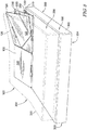
Fig. 4 is a rear perspective view of the head elevation apparatus, wherein a center panel is raised to the raised position by a bladder and an upper flap and a lower flap are folded inward toward the center panel; -
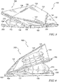
Fig. 5 is a side perspective view of the head elevation apparatus showing the top panel raised relative to the base panel by the bladder and an upper panel of the base panel raised relative to a lower panel of the base panel by another bladder; -
Fig. 6 is an opposite side perspective view of the head elevation apparatus showing the top panel raised relative to the base panel by the bladder and the upper panel of the base panel raised relative to the lower panel of the base panel by the other bladder; -
Fig. 7 is a rear perspective view of the head elevation apparatus showing the top panel raised relative to the base panel by the bladder and the upper panel of the base panel raised relative to the lower panel of the base panel by the other bladder; and -
Fig. 8 is a front perspective view of the head elevation apparatus in a raised position to alter a lateral and longitudinal angle of a mattress positioned over a patient support apparatus. - Referring to
Fig. 1 , ahead elevation apparatus 100 includes afront end 102 and aback end 104. A pair of side ends 106 extend between thefront end 102 and theback end 104. Theapparatus 100 includes abase panel 108 that is divided into aleft side 110 and aright side 112 by acenter line 114. Thebase panel 108 extends between thefront end 102 and theback end 104. Thebase panel 108 also extends between the side ends 106. Atop panel 120 is positioned over theright side 112 of thebase panel 108. It should be appreciated that thetop panel 120 may be positioned over theleft side 110 of thebase panel 108. In some embodiments, theapparatus 100 may include atop panel 120 positioned over each of theright side 112 and theleft side 110 of thebase panel 108. In some embodiments, theapparatus 100 may only include theright side 112 or theleft side 110. - The
top panel 120 includes acenter panel 122 that is hingedly coupled to thebase panel 108 along acenter hinge 124 for pivoting movement about a first axis 138 (shown inFig. 3 ). Anupper flap 126 is hingedly coupled to thecenter panel 122 along anupper hinge 128 for pivoting movement about a second axis 140 (shown inFig. 3 ). The remainingsides 130 of theupper flap 126 are not coupled to anything so that theupper flap 126 can move freely relative to thebase panel 108 as thecenter panel 122 is raised and lowered. Theupper flap 126 is triangular is shaped; however, it will be appreciated that theupper flap 126 may be formed with other shapes. In some embodiments, theupper flap 126 is a scalene triangle. Alower flap 132 is hingedly coupled to thecenter panel 122 along alower hinge 134 for pivoting movement about a third axis 142 (shown inFig. 3 ). The remainingsides 136 of thelower flap 132 are not coupled to anything so that thelower flap 132 can move freely relative to thebase panel 108 as thecenter panel 122 is raised and lowered. Thelower flap 132 is triangular in shape; however, it will be appreciated that thelower flap 132 may be formed with other shapes. In some embodiments, thelower flap 132 is a scalene triangle. - In some embodiments, hinges 124, 128, and 134 include piano hinges having hinge plates interconnected by a hinge pin that defines the
respective axes hinges hinges - The
first axis 138 of thecenter hinge 124 extends at anoblique angle 150 relative to thefront end 102. In some embodiments, theangle 150 is approximately 45 degrees. Thefirst axis 138 of thecenter hinge 124 also extends at oblique angles (not shown) relative to theback end 104 and the side ends 106. Thesecond axis 140 of theupper hinge 128 extends at anoblique angle 152 relative to thefront end 102. In some embodiments, theangle 152 is approximately 23 degrees. Thesecond axis 140 of the upper hinge also extends at oblique angles (not shown) relative to theback end 104 and the side ends 106. Thesecond axis 140 of theupper hinge 128 extends at anoblique angle 154 relative to thefirst axis 138 of thecenter hinge 124. In some embodiments, theangle 154 is approximately 68 degrees. Thethird axis 142 of thelower hinge 134 extends at anoblique angle 156 relative to thefront end 102. In some embodiments, theangle 156 is approximately 55.2 degrees. Thethird axis 142 of thelower hinge 134 also extends at oblique angles (not shown) relative to theback end 104 and the side ends 106. Thethird axis 142 of thelower hinge 134 extends at anoblique angle 158 relative to thefirst axis 138 of thecenter hinge 124. In some embodiments, theangle 158 is approximately 79.8 degrees. Thethird axis 142 of thelower hinge 134 also extends at anoblique angle 160 relative to thesecond axis 140 of theupper hinge 128. In some embodiments, theangle 160 is approximately 11.8 degrees. It will be appreciated, that theangles head elevation apparatus 100. In this disclosure, the term "oblique" means neither perpendicular nor parallel. - The
center panel 122 is configured to move between a collapsed position 170 (shown inFig. 1 ) and a raised position 172 (shown inFig. 3 ). Referring now toFig. 2 , thecenter panel 122 rotates about thefirst axis 138 of thecenter hinge 124 to the raisedposition 172 relative to thebase panel 108. When thecenter panel 122 is raised, theupper flap 126 rotates about thesecond axis 140 of theupper hinge 128 so that afree end 180 of theupper flap 126 moves inward away from theback end 104. Anotherfree end 182 of theupper flap 126 moves inward away from thecenter line 114. The degree to which the free ends 180, 182 move is dependent on how high thecenter panel 122 is raised. In thecollapsed position 170, thefree end 180 is substantially co-planar with theback end 104 and thefree end 182 is substantially co-planar with thecenter line 114. At the raisedposition 172, the free ends 180 and 182 are moved to maximum inward positions. If thecenter panel 122 is raised to an intermediate position between thecollapsed position 170 and the raisedposition 172, thefree end 180 is moved to an intermediate position between theback end 104 and the maximum position and thefree end 182 is moved to an intermediate position between thecenter line 114 and the maximum position. - When the
center panel 122 is raised, thelower flap 132 rotates about thethird axis 142 of thelower hinge 134 so that afree end 190 of thelower flap 132 moves inward away from thefront end 102. Anotherfree end 192 of thelower flap 132 moves inward away from theside end 106. The degree to which the free ends 190, 192 move is dependent on how high thecenter panel 122 is raised. In thecollapsed position 170, thefree end 190 is substantially co-planar with thefront end 102 and thefree end 192 is substantially co-planar with theside end 106. At the raisedposition 172, the free ends 190 and 192 are moved to maximum inward positions. If thecenter panel 122 is raised to an intermediate position between thecollapsed position 170 and the raisedposition 172, thefree end 190 is moved to an intermediate position between thefront end 102 and the maximum position and thefree end 192 is moved to an intermediate position between theside end 106 and the maximum position. - Referring to both
Figs. 1 and 2 , thecenter panel 122 is raised and lowered by a bladder (described in more detail below). That is, the bladder is inflated and deflated to move thecenter panel 122 between thecollapsed position 170 and the raisedposition 172. As illustrated inFigs. 1 and 2 , ahose 200 extends from the bladder to ablower 202. Theblower 202 is operable to inflate and deflate the bladder to raise and lower thecenter panel 122 between thecollapsed position 170 and the raisedposition 172. Acontroller 204 may be coupled to theblower 202 to control theblower 202. Thecontroller 204 may include inputs that allow a user to inflate or deflate the bladder to position thecenter panel 122 at thecollapsed position 170, the raisedposition 172, or a desired intermediate position between thecollapsed position 170 and the raisedposition 172. - In some embodiments, the
controller 204 is separate from the blower 202 (as illustrated) and may be positioned adjacent a patient support apparatus. In other embodiments, thecontroller 204 may be incorporated into a housing of theblower 202. In yet another embodiment, thecontroller 204 may be a pendant that a user can operate while positioned on a patient support apparatus. Accordingly, the user may adjust a height of thecenter panel 122 while positioned on the patient support apparatus and supported by thehead elevation apparatus 100. - Referring to
Fig. 4 , abladder 220 is positioned between thebase panel 108 and thetop panel 120. Thebladder 220 extends between thebase panel 108 and thecenter panel 122. Thebladder 220 is illustrated with anupper bladder 222 and alower bladder 224. Theupper bladder 222 is positioned above thelower bladder 224. Theupper bladder 222 and thelower bladder 224 are in fluid communication. The combination of theupper bladder 222 and thelower bladder 224 facilitates balancing thecenter panel 122 on thebladder 220. It should be noted that thebladder 220 may include any number of bladder sections, including only one bladder section. Theupper bladder 222 is positioned adjacent to and in contact with thecenter panel 122. Thelower bladder 224 is positioned adjacent to and in contact with thebase panel 108. - As the
bladder 220 is inflated, thecenter panel 122 raises relative to thebase panel 108. Thebladder 220 may be inflated to any desired pressure to raise thecenter panel 122 to a desired intermediate position between thecollapsed position 170 and the raisedposition 172. As illustrated inFig. 4 , when thecenter panel 122 is raised, theupper flap 126 is rotated inward. Likewise, thelower flap 132 is rotated inward when thecenter panel 122 is raised. In some embodiments, at least one of theupper flap 126 and thelower flap 132 may rotate into contact with thebladder 220 to inhibit further inward movement of theupper flap 126 and thelower flap 132. However, as illustrated inFig. 4 , theupper flap 126 and thelower flap 132 do not need to contact thebladder 220 to maintain a respective position of theupper flap 126 and thelower flap 132. -
Fig. 4 illustrates asingle bladder 220 configured to raise and lower thecenter panel 122. It will be appreciated that theapparatus 100 may include any number ofbladders 220 to raise and lower thecenter panel 122. For example, an array ofbladders 220 may be configured to raise and lower thecenter panel 122. In such an embodiment, eachbladder 220 of the array ofbladders 220 may be inflated to a different pressure to balance thecenter panel 122. In other embodiments, an actuator other than thebladder 220 may be utilized to raise and lower thecenter panel 122. For example, thecenter panel 122 may be raised and lowered by a hydraulic mechanism. - Referring to
Fig. 5 , in some embodiments, thebase panel 108 includes anupper panel 250 and alower panel 252. Theupper panel 250 is hingedly attached to thelower panel 252 along abase hinge 254 that extends along thefront end 102. Thecenter hinge 124 extends at theoblique angle 150 relative to thebase hinge 254. Theupper hinge 128 extends at theoblique angle 152 relative to thebase hinge 254. Thelower hinge 134 extends at theoblique angle 156 relative to thebase hinge 254. - The
upper panel 250 may be raised and lowered between a retracted position 260 (shown inFigs. 1-4 ) and an extended position 262 (shown inFigs. 5-8 ) relative to thelower panel 252. Abladder 270 is positioned between theupper panel 250 and thelower panel 252. Thebladder 270 is inflated and deflated to raise and lower theupper panel 250 between the retractedposition 260 and theextended position 262. Thebladder 270 may also be inflated and deflated to a pressure that positions theupper panel 250 at an intermediate position between the retractedposition 260 and theextended position 262. Thebladder 270 may be inflated and deflated by theblower 202. That is theblower 202 may inflate and deflate thebladder 270 and thebladder 220 simultaneously. Optionally, a valve (not shown) may be provided to directed airflow from theblower 202 to one of thebladder 270 or thebladder 220. In some embodiments, theapparatus 100 may include twoblowers 202, wherein eachblower 202 operates one of thebladders controller 204 may be utilized to control the inflation and deflation of each of thebladders bladder 270 is illustrated as having a single section; however, thebladder 270 may include any number of sections. - As illustrated in
Fig. 6 , bothbladders bladder 220 may be inflated to raise thecenter panel 122, while thebladder 270 is operated to raise theupper panel 250. Thecenter panel 122 is raised and lowered to alter a lateral angle of theapparatus 100, whereas theupper panel 250 is raised and lowered to alter a longitudinal angle of theapparatus 100. By adjusting thebladder 220 and thebladder 270 at the same time, both the later angle and the longitudinal angle of theapparatus 100 are adjusted. However, thebladder 220 may be adjusted alone to adjust only the lateral angle. Likewise, thebladder 270 may be adjusted alone to alter only the longitudinal angle. When operating theapparatus 100, both thebladder 220 and thebladder 270 may be inflated or deflated to different intermediate positions to provide a desired lateral angle and a desired longitudinal angle. - Referring to
Fig. 7 , theapparatus 100 includes twobladders 270 on theright side 112 and twobladder 270 on theleft side 110. Accordingly, each of thesides apparatus 100 may be raised and lowered. Notably, eachside bladders 270, for example one. As illustrated, thebladders 270 may all be adjusted to alter a longitudinal angle of bothsides right side 112 also includes thetop panel 120. Thecenter panel 122 of thetop panel 120 may also be raised and lowered to alter the lateral angle of theright side 112. -
Fig. 8 illustrates apatient support apparatus 300 having ahead end 302 and afoot end 304. Aright side 306 and aleft side 308 extend between thehead end 302 and thefoot end 304. A longitudinal axis 310 (shown inFig. 3 ) extends from thehead end 302 to thefoot end 304. A lateral axis 312 (shown inFig. 3 ) extends from theright side 306 to theleft side 308. Theapparatus 100 is positioned at thehead end 302 of thepatient support apparatus 300. Amattress 320 having ahead end 322 is positioned over thepatient support apparatus 300 so that theapparatus 100 is positioned between thehead end 302 of thepatient support apparatus 300 and thehead end 322 of themattress 320. Thehead end 322 of themattress 320 includes aright side 330 and aleft side 332. Theright side 330 of themattress 320 is positioned over theright side 112 of theapparatus 100, and theleft side 332 of themattress 320 is positioned over theleft side 110 of theapparatus 100. - In the illustrated embodiment, the
upper panel 250 is illustrated in theextended position 262 to raise thehead end 322 of themattress 320 and alter a longitudinal angle of thehead end 322 of themattress 320. Also, thecenter panel 122 is raised to the raisedposition 172 to alter a lateral angle of theright side 330 of themattress 320. It should be noted that only thecenter panel 122 may be raised to the raisedposition 172 to alter the lateral angle, while theupper panel 250 is in the retractedposition 260. Likewise, only theupper panel 250 may be raised to theextended position 262 to alter the longitudinal angle, while thecenter panel 122 is in thecollapsed position 170. As set forth above, both thecenter panel 122 and theupper panel 250 may be raised or lowered to intermediate positions where in each of the lateral angles and the longitudinal angles are different. - The
apparatus 100 provides graduated lateral rotation (GLR) as a therapy for sleep disordered breathing. The apparatus allows GLR to be added to any existing consumer bed that conforms to an adjustable frame (e.g., viscoelastic foam or air bladder) by introducing an adjustable wedge below the mattress in the head and torso sections. Theapparatus 100 includes an upper module that creates a lateral angle under the mattress. In another embodiment, theapparatus 100 may also include a lower module to create a longitudinal angle (or "elevated head of bed" position). The upper module can be mounted on the lower module. - The upper module uses a single bladder and a single hinged panel to provide improved comfort by creating a more continuous support of the mattress and reducing variation that could be uncomfortable to users. The
apparatus 100 also provides improved mattress wear by supporting the mattress continuously rather than leaving areas of the mattress unsupported, potentially resulting in mattress damage, wear, or breakdown. The lower module supplements the laterally angled surface of the upper module to improved comfort by providing a raised (e.g., 5-15 degree) angle under the laterally angled support. The modular nature of theapparatus 100 also simplifies installation and reduces shipping cost and burden. - Although this disclosure refers to multiple embodiments, it will be appreciated that aspects of each embodiment may be utilized with other embodiments described herein.
- Although this disclosure refers to specific embodiments, it will be understood by those skilled in the art that various changes in form and detail may be made.
- Embodiments of the invention can be described with reference to the following numbered clauses, with preferred features laid out in the dependent clauses:
- 1. A head elevation apparatus configured to be positioned under a mattress, the apparatus comprising:
- a base panel, and
- a top panel positioned on the base panel, the top panel comprising:
- a center panel hingedly coupled to the base panel,
- an upper flap hingedly coupled to the center panel, and
- a lower flap hingedly coupled to the center panel,
- wherein the center panel is configured to move between a collapsed position and a raised position relative to the base panel, and
- wherein, when the center panel is moved to the raised position, the upper flap and the lower flap rotate relative to the center panel.
- 2. The apparatus of clause 1, wherein the center panel is hingedly coupled to the base panel along a center hinge that extends at a first oblique angle relative to a front face of the base panel.
- 3. The apparatus of
clause 2, wherein the upper flap is hingedly coupled to the center panel along an upper hinge that extends at a second oblique angle relative to the front face. - 4. The apparatus of
clause 3, wherein the upper hinge extends at a third oblique angle relative to the center hinge. - 5. The apparatus of any one of
clauses 2 to 4, wherein the lower flap is hingedly coupled to the center panel along a lower hinge that extends at a fourth oblique angle relative to the front face. - 6. The apparatus of clause 5, wherein the lower hinge extends at a fifth oblique angle relative to the center hinge.
- 7. The apparatus of any one of
clauses 2 to 6, wherein
the upper flap is hingedly coupled to the center panel along an upper hinge,
the lower flap is hingedly coupled to the center panel along a lower hinge, and
the lower hinge extends at a sixth oblique angle relative to the upper hinge. - 8. The apparatus of any preceding clause, wherein moving the center panel to the raised position alters a lateral angle of the mattress.
- 9. The apparatus of clause 8, wherein the center panel is movable to a plurality of intermediate positions between the collapsed position and the raised position, wherein the lateral angle of the mattress is different at each intermediate position.
- 10. The apparatus of any preceding clause, further comprising a bladder positioned between the base panel and the center panel, the bladder being inflatable and deflatable to move the center panel between the collapsed position and the raised position.
- 11. The apparatus of clause 10, wherein the bladder includes a lower bladder and an upper bladder coupled to the lower bladder.
- 12. The apparatus of clause 11, wherein:
- the upper bladder is positioned adjacent the center panel, and
- the lower bladder is positioned adjacent the base panel.
- 13. The apparatus of any preceding clause, wherein the base panel includes a lower panel and an upper panel, the upper panel being hingedly coupled to the lower panel and configured to move between a retracted positioned and an extended position.
- 14. The apparatus of clause 13, wherein the upper panel moves to the extended position to alter a longitudinal angle of the mattress.
- 15. The apparatus of either clause 13 or clause 14, wherein the upper panel is movable to a plurality of intermediate positions between the retracted positioned and the extended position.
- 16. The apparatus of any one of clauses 13 to 15, further comprising a bladder positioned between the upper panel and the lower panel, the bladder being inflatable and deflatable to move the upper panel between the retracted position and the extended position.
- 17. The apparatus of clause 16, wherein the bladder includes an upper bladder and a lower bladder coupled to the upper bladder.
- 18. The apparatus of clause 17, wherein:
- the upper bladder is positioned adjacent the upper panel, and
- the lower bladder is positioned adjacent the lower panel.
- 19. A head elevation apparatus configured to be positioned under a mattress, the apparatus comprising:
- a base panel, and
- a top panel positioned on the base panel, the top panel comprising:
- a center panel hingedly coupled to the base panel along a center hinge that extends at a first oblique angle relative to a front face of the base panel,
- an upper flap hingedly coupled to the center panel along an upper hinge that extends at a second oblique angle relative to the front face, the upper hinge extending at a third oblique angle relative to the center hinge, and
- a lower flap hingedly coupled to the center panel along a lower hinge that extends at a fourth oblique angle relative to the front face, wherein the lower hinge extends at a fifth oblique angle relative to the center hinge,
- wherein the center panel is configured to move between a collapsed position and a raised position relative to the base panel, and
- wherein, when the center panel is moved to the raised position, the upper flap and the lower flap rotate relative to the center panel.
- 20. The apparatus of either clause 19 or clause 20, wherein the lower hinge extends at a sixth oblique angle relative to the upper hinge.
- 21. The apparatus of either clause 19 or clause 20, wherein moving the center panel to the raised position alters a lateral angle of the mattress.
- 22. The apparatus of clause 21, wherein the center panel is movable to a plurality of intermediate positions between the collapsed position and the raised position, wherein the lateral angle of the mattress is different at each intermediate position.
- 23. The apparatus of any one of clauses 19 to 22, further comprising a bladder positioned between the base panel and the center panel, the bladder being inflatable and deflatable to move the center panel between the collapsed position and the raised position.
- 24. The apparatus of clause 23, wherein the bladder includes a lower bladder and an upper bladder coupled to the lower bladder.
- 25. The apparatus of clause 24, wherein:
- the upper bladder is positioned adjacent the center panel, and
- the lower bladder is positioned adjacent the base panel.
- 26. The apparatus of any one of clauses 19 to 25, wherein the base panel includes a lower panel and an upper panel, the upper panel being hingedly coupled to the lower panel and configured to move between a retracted positioned and an extended position.
- 27. The apparatus of clause 26, wherein the upper panel moves to the extended position to alter a longitudinal angle of the mattress.
- 28. The apparatus of either clause 26 or clause 27, wherein the upper panel is movable to a plurality of intermediate positions between the retracted positioned and the extended position.
- 29. The apparatus of any one of clauses 26 to 28, further comprising a bladder positioned between the upper panel and the lower panel, the bladder being inflatable and deflatable to move the upper panel between the retracted position and the extended position.
- 30. The apparatus of clause 29, wherein the bladder includes an upper bladder and a lower bladder coupled to the upper bladder.
- 31. The apparatus of clause 30, wherein:
- the upper bladder is positioned adjacent the upper panel, and
- the lower bladder is positioned adjacent the lower panel.
- 32. A head elevation apparatus configured to be positioned under a mattress, the apparatus comprising:
- a base panel, and
- a top panel positioned on the base panel, the top panel comprising:
- a center panel hingedly coupled to the base panel along a center hinge,
- an upper flap hingedly coupled to the center panel along an upper hinge, and
- a lower flap hingedly coupled to the center panel along a lower hinge,
- wherein the center panel is configured to move between a collapsed position and a raised position relative to the base panel, and
- wherein, when the center panel is moved to the raised position, the upper flap and the lower flap rotate relative to the center panel.
- 33. The apparatus of clause 32, wherein the center hinge extends at a first oblique angle relative to a front face of the base panel.
- 34. The apparatus of clause 33, wherein the upper hinge extends at a second oblique angle relative to the front face.
- 35. The apparatus of clause 34, wherein the upper hinge extends at a third oblique angle relative to the center hinge.
- 36. The apparatus of clause 33, wherein the lower hinge extends at a fourth oblique angle relative to the front face.
- 37. The apparatus of clause 36, wherein the lower hinge extends at a fifth oblique angle relative to the center hinge.
- 38. The apparatus of clause 33, wherein the lower hinge extends at a sixth oblique angle relative to the upper hinge.
- 39. The apparatus of any one of clauses 32 to 38, wherein moving the center panel to the raised position alters a lateral angle of the mattress.
- 40. The apparatus of clause 39, wherein the center panel is movable to a plurality of intermediate positions between the collapsed position and the raised position, wherein the lateral angle of the mattress is different at each intermediate position.
- 41. The apparatus of any one of clauses 32 to 40, further comprising a bladder positioned between the base panel and the center panel, the bladder being inflatable and deflatable to move the center panel between the collapsed position and the raised position.
- 42. The apparatus of clause 41, wherein the bladder includes a lower bladder and an upper bladder coupled to the lower bladder.
- 43. The apparatus of clause 42, wherein:
- the upper bladder is positioned adjacent the center panel, and
- the lower bladder is positioned adjacent the base panel.
- 44. The apparatus of any one of clauses 32 to 43, wherein the base panel includes a lower panel and an upper panel, the upper panel being hingedly coupled to the lower panel and configured to move between a retracted positioned and an extended position.
- 45. The apparatus of clause 44, wherein the upper panel moves to the extended position to alter a longitudinal angle of the mattress.
- 46. The apparatus of either clause 44 or clause 45, wherein the upper panel is movable to a plurality of intermediate positions between the retracted positioned and the extended position.
- 47. The apparatus of any one of clauses 44 to 46, further comprising a bladder positioned between the upper panel and the lower panel, the bladder being inflatable and deflatable to move the upper panel between the retracted position and the extended position.
- 48. The apparatus of clause 47, wherein the bladder includes an upper bladder and a lower bladder coupled to the upper bladder.
- 49. The apparatus of clause 48, wherein:
- the upper bladder is positioned adjacent the upper panel, and
- the lower bladder is positioned adjacent the lower panel.
- 50. A head elevation apparatus configured to be positioned under a mattress, the apparatus comprising:
- a base panel,
- a top panel positioned on the base panel, the top panel comprising:
- a center panel hingedly coupled to the base panel,
- an upper flap hingedly coupled to the center panel, and
- a lower flap hingedly coupled to the center panel,
- a first bladder positioned between the center panel and the base panel, and
- a blower coupled to the first bladder to inflate and deflate the first bladder,
- wherein the center panel is configured to move between a collapsed position and a raised position relative to the base panel when the first bladder is inflated and deflated, and
- wherein, when the center panel is moved to the raised position, the upper flap and the lower flap rotate relative to the center panel.
- 51. The apparatus of clause 50, wherein the center panel is hingedly coupled to the base panel along a center hinge that extends at a first oblique angle relative to a front face of the base panel.
- 52. The apparatus of clause 51, wherein the upper panel is hingedly coupled to the center panel along an upper hinge that extends at a second oblique angle relative to the front face.
- 53. The apparatus of clause 52, wherein the upper hinge extends at a third oblique angle relative to the center hinge.
- 54. The apparatus of clause 51, wherein the lower panel is hingedly coupled to the center panel along a lower hinge that extends at a fourth oblique angle relative to the front face.
- 55. The apparatus of clause 54, wherein the lower hinge extends at a fifth oblique angle relative to the center hinge.
- 56. The apparatus of clause 51, wherein
- the upper panel is hingedly coupled to the center panel along an upper hinge,
- the lower panel is hingedly coupled to the center panel along a lower hinge, and
- the lower hinge extends at a sixth oblique angle relative to the upper hinge.
- 57. The apparatus of any one of clauses 50 to 56, wherein moving the center panel to the raised position alters a lateral angle of the mattress.
- 58. The apparatus of clause 57, wherein the center panel is movable to a plurality of intermediate positions between the collapsed position and the raised position, wherein the lateral angle of the mattress is different at each intermediate position.
- 59. The apparatus of any one of clauses 50 to 58, wherein the base panel includes a lower panel and an upper panel, the upper panel being hingedly coupled to the lower panel and configured to move between a retracted positioned and an extended position.
- 60. The apparatus of clause 59, wherein the upper panel moves to the extended position to alter a longitudinal angle of the mattress.
- 61. The apparatus of clause 60, wherein the upper panel is movable to a plurality of intermediate positions between the retracted positioned and the extended position.
- 62. The apparatus of any one of clauses 59 to 61, further comprising a second bladder positioned between the upper panel and the lower panel, the second bladder being inflatable and deflatable to move the upper panel between the retracted position and the extended position.
- 63. A head elevation apparatus configured to be positioned under a mattress, the apparatus comprising:
- a base panel comprising a lower panel and an upper panel, the upper panel being hingedly coupled to the lower panel and configured to move between a retracted positioned and an extended position,
- a top panel positioned on the base panel, the top panel comprising:
- a center panel hingedly coupled to the base panel, wherein the center panel is configured to move between a collapsed position and a raised position relative to the base panel,
- an upper flap hingedly coupled to the center panel, and
- a lower flap hingedly coupled to the center panel,
- a first bladder positioned between the center panel and the base panel, and
- a second bladder positioned between the upper panel and the lower panel,
- wherein, when the center panel is moved to the raised position, the upper flap and the lower flap rotate relative to the center panel to alter a lateral angle of the mattress, and
- wherein the upper panel moves to the extended position to alter a longitudinal angle of the mattress.
- 64. The apparatus of clause 63, wherein the center panel is hingedly coupled to the base panel along a center hinge that extends at a first oblique angle relative to a front face of the base panel.
- 65. The apparatus of clause 64, wherein the upper panel is hingedly coupled to the center panel along an upper hinge that extends at a second oblique angle relative to the front face.
- 66. The apparatus of clause 65, wherein the upper hinge extends at a third oblique angle relative to the center hinge.
- 67. The apparatus of clause 63, wherein the lower panel is hingedly coupled to the center panel along a lower hinge that extends at a fourth oblique angle relative to the front face.
- 68. The apparatus of clause 67, wherein the lower hinge extends at a fifth oblique angle relative to the center hinge.
- 69. The apparatus of clause 63, wherein
- the upper panel is hingedly coupled to the center panel along an upper hinge,
- the lower panel is hingedly coupled to the center panel along a lower hinge, and
- the lower hinge extends at a sixth oblique angle relative to the upper hinge.
- 70. The apparatus of any one of clauses 63 to 69, wherein the center panel is movable to a plurality of intermediate positions between the collapsed position and the raised position, wherein the lateral angle of the mattress is different at each intermediate position.
- 71. The apparatus of any one of clauses 63 to 70, wherein the upper panel is movable to a plurality of intermediate positions between the retracted positioned and the extended position.
Claims (15)
- A head elevation apparatus configured to be positioned under a mattress, the apparatus comprising:a base panel, anda top panel positioned on the base panel, the top panel comprising:a center panel hingedly coupled to the base panel,an upper flap hingedly coupled to the center panel, anda lower flap hingedly coupled to the center panel,wherein the center panel is configured to move between a collapsed position and a raised position relative to the base panel, andwherein, when the center panel is moved to the raised position, the upper flap and the lower flap rotate relative to the center panel.
- The apparatus of claim 1, wherein the center panel is hingedly coupled to the base panel along a center hinge that extends at a first oblique angle relative to a front face of the base panel.
- The apparatus of claim 2, wherein the upper flap is hingedly coupled to the center panel along an upper hinge that extends at a second oblique angle relative to the front face.
- The apparatus of claim 3, wherein the upper hinge extends at a third oblique angle relative to the center hinge.
- The apparatus of any one of claims 2 to 4, wherein the lower flap is hingedly coupled to the center panel along a lower hinge that extends at a fourth oblique angle relative to the front face.
- The apparatus of claim 5, wherein the lower hinge extends at a fifth oblique angle relative to the center hinge.
- The apparatus of any one of claims 2 to 6, wherein
the upper flap is hingedly coupled to the center panel along an upper hinge,
the lower flap is hingedly coupled to the center panel along a lower hinge, and
the lower hinge extends at a sixth oblique angle relative to the upper hinge. - The apparatus of any preceding claim, further comprising a bladder positioned between the base panel and the center panel, the bladder being inflatable and deflatable to move the center panel between the collapsed position and the raised position.
- The apparatus of claim 8, wherein the bladder includes a lower bladder and an upper bladder coupled to the lower bladder.
- The apparatus of any preceding claim, wherein:the upper bladder is positioned adjacent the center panel, andthe lower bladder is positioned adjacent the base panel.
- The apparatus of any preceding claim, wherein the base panel includes a lower panel and an upper panel, the upper panel being hingedly coupled to the lower panel and configured to move between a retracted positioned and an extended position.
- The apparatus of claim 11, wherein the upper panel is movable to a plurality of intermediate positions between the retracted positioned and the extended position.
- The apparatus of either claim 11 or claim 12, further comprising a bladder positioned between the upper panel and the lower panel, the bladder being inflatable and deflatable to move the upper panel between the retracted position and the extended position.
- The apparatus of claim 13, wherein the bladder includes an upper bladder and a lower bladder coupled to the upper bladder.
- The apparatus of claim 14, wherein:the upper bladder is positioned adjacent the upper panel, andthe lower bladder is positioned adjacent the lower panel.
Applications Claiming Priority (1)
| Application Number | Priority Date | Filing Date | Title |
|---|---|---|---|
| US201962811605P | 2019-02-28 | 2019-02-28 |
Publications (2)
| Publication Number | Publication Date |
|---|---|
| EP3701925A1 true EP3701925A1 (en) | 2020-09-02 |
| EP3701925B1 EP3701925B1 (en) | 2024-04-17 |
Family
ID=69645892
Family Applications (1)
| Application Number | Title | Priority Date | Filing Date |
|---|---|---|---|
| EP20157754.1A Active EP3701925B1 (en) | 2019-02-28 | 2020-02-17 | Oblique hinged panels and bladder apparatus for sleep disorders |
Country Status (2)
| Country | Link |
|---|---|
| US (2) | US10959534B2 (en) |
| EP (1) | EP3701925B1 (en) |
Cited By (1)
| Publication number | Priority date | Publication date | Assignee | Title |
|---|---|---|---|---|
| US10959534B2 (en) * | 2019-02-28 | 2021-03-30 | Hill-Rom Services, Inc. | Oblique hinged panels and bladder apparatus for sleep disorders |
Citations (3)
| Publication number | Priority date | Publication date | Assignee | Title |
|---|---|---|---|---|
| US4142263A (en) * | 1977-11-25 | 1979-03-06 | Maine Ideas Incorporated | Bed-mattress elevating system and the like |
| DE3418072A1 (en) * | 1984-05-16 | 1985-11-21 | Daniel Kollbrunn Küng | Device for the vertical adjustment of bed parts and the like |
| WO2013177338A2 (en) * | 2012-05-22 | 2013-11-28 | Hill-Rom Services, Inc. | Adverse event mitigation systems, methods and devices |
Family Cites Families (194)
| Publication number | Priority date | Publication date | Assignee | Title |
|---|---|---|---|---|
| US948644A (en) | 1908-06-23 | 1910-02-08 | Andrew Bjornstad | Mattress. |
| US1610898A (en) | 1923-10-05 | 1926-12-14 | Cleveland R Steiner | Pneumatic mattress |
| US2612645A (en) | 1949-09-13 | 1952-10-07 | Boland Gus Leslie | Reclining air cushion |
| US2769182A (en) * | 1954-04-21 | 1956-11-06 | Erwin J Nunlist | Inflatable mattress lifters |
| US2887692A (en) | 1956-05-23 | 1959-05-26 | Gosman Clarence Berveir | Inflatable cushion or the like |
| US3392723A (en) * | 1965-08-09 | 1968-07-16 | Richfield Oil Corp | Electro-pneumatically operated bed oscillator |
| GB1126364A (en) | 1965-10-18 | 1968-09-05 | Uniroyal Ltd | An inflatable cushion, seat, mattress or other like article |
| US3392412A (en) | 1967-01-12 | 1968-07-16 | Aymar Julian Robert | Adjustable bedrest |
| US3606623A (en) | 1970-01-09 | 1971-09-21 | Surgical Dynamics Inc | Adjustable bedrest with improved bellows structure |
| US3636573A (en) * | 1970-01-29 | 1972-01-25 | Con Tex Corp | Foldable mattress support |
| US3667075A (en) | 1970-02-24 | 1972-06-06 | Wesley D Ballard | Mattress spring bellows assembly as for hospitals, and the like |
| US3781928A (en) | 1971-04-05 | 1974-01-01 | Erik Pettersson | Device for raising the head end and/or foot end of a bed |
| US3775785A (en) | 1972-12-26 | 1973-12-04 | T Mittendorf | Adjustable pillow apparatus |
| US4127906A (en) * | 1976-07-15 | 1978-12-05 | Zur Henry C | Adjustable bed-chair |
| US4287620A (en) * | 1978-06-02 | 1981-09-08 | Zur Henry C | Multi-feature and variable function body supporting assembly and sideguards |
| US4151407A (en) | 1977-04-28 | 1979-04-24 | Texas Instruments Incorporated | Low-power, infrared information transmission system |
| US4150284A (en) | 1977-04-28 | 1979-04-17 | Texas Instruments Incorporated | Medical patient condition monitoring system |
| US4165125A (en) | 1977-06-08 | 1979-08-21 | National Seating Company | Slipover headrest pillow assembly |
| JPS5438512U (en) | 1977-08-19 | 1979-03-14 | ||
| US4216462A (en) | 1978-03-06 | 1980-08-05 | General Electric Company | Patient monitoring and data processing system |
| US4183015A (en) | 1978-06-26 | 1980-01-08 | Hill-Rom Company, Inc. | Side guard for bed including means for controlling remote electrical devices |
| US4225953A (en) | 1978-09-29 | 1980-09-30 | Simon William F | Personnel locator |
| US4228426A (en) | 1978-09-29 | 1980-10-14 | Roberts William A | Hospital bed monitor |
| US4225988A (en) * | 1979-01-30 | 1980-10-07 | Cary George R | Ortho-turn bed |
| US4237344A (en) | 1979-04-20 | 1980-12-02 | Hospital Communication Systems, Inc. | Rapid response health care communications system |
| US4331953A (en) | 1979-12-26 | 1982-05-25 | The Boeing Company | Communication system for use in hazardous confined areas |
| US4309783A (en) | 1980-02-06 | 1982-01-12 | Teledyne Industries, Inc. | Adjustably conformable bed |
| US4298863A (en) | 1980-02-10 | 1981-11-03 | St. Anthony Hospital Systems | Portable patient call |
| US4601064A (en) | 1983-01-13 | 1986-07-15 | Fisher Berkeley Corporation | Communication system |
| US5062151A (en) | 1983-01-13 | 1991-10-29 | Fisher Berkeley Corporation | Communication system |
| US4527298A (en) | 1982-03-18 | 1985-07-09 | Moulton Lee A | Electro pneumatic bed |
| US4649385A (en) | 1982-08-13 | 1987-03-10 | Teloc R & D Ltd. | Electronic locating system for persons receiving telephone calls |
| JPS5993524U (en) | 1982-12-15 | 1984-06-25 | 狩野 千世子 | Air mat type bed operated by computer |
| US4598275A (en) | 1983-05-09 | 1986-07-01 | Marc Industries Incorporated | Movement monitor |
| US4577185A (en) | 1983-07-29 | 1986-03-18 | Saint Margaret Hospital | Construction for alerting health-care professionals |
| US4554693A (en) | 1983-12-19 | 1985-11-26 | American Fast Print Limited | Mattress, box springs fabric |
| DE3400804A1 (en) * | 1984-01-12 | 1985-07-18 | Daniel Kollbrunn Küng | DEVICE FOR ADJUSTING THE BED OF A BED IN THE AREA OF THE HEAD OR FOOT |
| US4593273A (en) | 1984-03-16 | 1986-06-03 | Narcisse Bernadine O | Out-of-range personnel monitor and alarm |
| US4578671A (en) | 1984-12-05 | 1986-03-25 | International Business Machines Corp. | Remote indicating low battery voltage enunciator method and apparatus |
| JPH078288B2 (en) * | 1985-05-10 | 1995-02-01 | メディスカス プロダクツ リミテッド | Patient support equipment |
| US4680790A (en) | 1985-08-22 | 1987-07-14 | Joerns Healthcare, Inc. | Bedside control module for healthcare stations and the like |
| US5103108A (en) | 1985-10-17 | 1992-04-07 | Crimmins James W | Distributed infrared communication system |
| US4807313A (en) | 1985-12-03 | 1989-02-28 | Ryder International Corporation | Inflatable inclined mattress support system |
| US4754510A (en) | 1986-03-06 | 1988-07-05 | King Harry A | Body pillow |
| US4967195A (en) | 1986-05-08 | 1990-10-30 | Shipley Robert T | Hospital signaling and communications system |
| US4955000A (en) | 1986-07-17 | 1990-09-04 | Nac Engineering And Marketing, Inc. | Ultrasonic personnel location identification system |
| EP0262771B1 (en) | 1986-08-06 | 1991-04-24 | Turnblade Ltd. | Tilting bed |
| US4814751A (en) | 1987-02-27 | 1989-03-21 | Wildlife Materials, Inc. | Patient tracking system |
| US4839932A (en) | 1987-05-26 | 1989-06-20 | Williamson Robert M | Adjustable bed system |
| US4850040A (en) | 1987-07-01 | 1989-07-18 | Inncom International, Inc. | Infrared remote control system for activating and deactivating one or more devices in a single enclosed space |
| JPH01238859A (en) | 1988-03-18 | 1989-09-25 | Sanei Seisakusho:Kk | Bed |
| US4841221A (en) | 1988-04-27 | 1989-06-20 | Lutron Electronics Co., Inc. | Position-sensing circuit |
| EP0340325B1 (en) | 1988-05-05 | 1991-02-20 | Hewlett-Packard GmbH | Digitally addressable electronic device |
| US4877288A (en) | 1988-09-06 | 1989-10-31 | Susan Lee | Lounge chair cover |
| US4998939A (en) | 1988-09-28 | 1991-03-12 | R & P Joint Venture | Hospital bed with guard rail actuated safety apparatus |
| US5153584A (en) | 1989-03-17 | 1992-10-06 | Cardiac Evaluation Center, Inc. | Miniature multilead biotelemetry and patient location system |
| US5124991A (en) | 1989-03-30 | 1992-06-23 | Photonics Corporation | Error correction for infrared data communication |
| US5181288A (en) * | 1989-05-30 | 1993-01-26 | The Mediscus Group Inc. | Therapeutic turning bed |
| US4932089A (en) | 1989-08-02 | 1990-06-12 | Laviero Frank D | Beach pillow |
| US4990892A (en) | 1989-08-07 | 1991-02-05 | Westcom, A Division Of Westside Communications Of Jacksonville, Inc. | Personnel locator system |
| US4998095A (en) | 1989-10-19 | 1991-03-05 | Specific Cruise Systems, Inc. | Emergency transmitter system |
| US5036852A (en) | 1989-12-08 | 1991-08-06 | Leishman Mark L | Medical equipment monitor apparatus and method |
| US5012539A (en) | 1990-02-13 | 1991-05-07 | Grigg Ellen S | Inflatable multi-purpose medical support pillow |
| US5086290A (en) | 1990-03-08 | 1992-02-04 | Murray Shawn G | Mobile perimeter monitoring system |
| US5060174A (en) | 1990-04-18 | 1991-10-22 | Biomechanics Corporation Of America | Method and apparatus for evaluating a load bearing surface such as a seat |
| CH681591A5 (en) | 1990-11-22 | 1993-04-30 | Friedrich W Mumenthaler | |
| US5092007A (en) | 1991-02-21 | 1992-03-03 | Hasty Charles E | Air mattress overlay for lateral patient roll |
| JPH04297257A (en) | 1991-03-27 | 1992-10-21 | Koshin Rubber Kk | Nursing instrument |
| US5097551A (en) | 1991-05-20 | 1992-03-24 | Smith Jason D | Skeletal support pillow |
| US5144284A (en) | 1991-05-22 | 1992-09-01 | Hammett Rawlings H | Patient-monitoring bed covering device |
| US5253656A (en) | 1991-05-23 | 1993-10-19 | Rincoe Richard G | Apparatus and method for monitoring contact pressure between body parts and contact surfaces |
| US5137033A (en) | 1991-07-15 | 1992-08-11 | Norton John L | Patient monitoring device |
| US5184112A (en) | 1991-09-11 | 1993-02-02 | Gaymar Industries, Inc. | Bed patient position monitor |
| US5269388A (en) | 1991-11-12 | 1993-12-14 | Stress-Tek, Inc. | Weighing bed |
| US5170522A (en) | 1991-12-16 | 1992-12-15 | Select Comfort Corporation | Air adjustable bed |
| US5415167A (en) | 1992-01-10 | 1995-05-16 | Wilk; Peter J. | Medical system and associated method for automatic diagnosis and treatment |
| US5276432A (en) | 1992-01-15 | 1994-01-04 | Stryker Corporation | Patient exit detection mechanism for hospital bed |
| US5195198A (en) | 1992-01-15 | 1993-03-23 | Stryker Corporation | Fail-safe bed motion control circuit having a microprocessor |
| US5353012A (en) | 1992-05-14 | 1994-10-04 | Bartronix, Inc. | Bed position and activity sensing apparatus |
| US5311625A (en) | 1992-07-22 | 1994-05-17 | Truman Products | Portable, integrated, universally adjustable position control system |
| US5577278A (en) | 1992-07-22 | 1996-11-26 | Princeton Products Inc. | Portable, integrated, universally adjustable position control system |
| ATE166734T1 (en) | 1992-12-11 | 1998-06-15 | Siemens Medical Systems Inc | DOCKING STATION FOR PATIENT MONITORING SYSTEM |
| US5425150A (en) * | 1993-06-17 | 1995-06-20 | Palmer, Jr.; John M. | Articulating device for a flat bed |
| US5838223A (en) | 1993-07-12 | 1998-11-17 | Hill-Rom, Inc. | Patient/nurse call system |
| US5345630A (en) | 1993-07-15 | 1994-09-13 | Jack Healy | Quick inflatable air mattress |
| US5715548A (en) | 1994-01-25 | 1998-02-10 | Hill-Rom, Inc. | Chair bed |
| US5500964A (en) * | 1994-03-09 | 1996-03-26 | National Health Equipment, Inc. | Patient manipulating kit and method of converting a hospital bed to a patient manipulation apparatus |
| US5490295A (en) | 1994-04-15 | 1996-02-13 | Boyd; Dennis | Water mattress and air mattress construction |
| US5611096A (en) | 1994-05-09 | 1997-03-18 | Kinetic Concepts, Inc. | Positional feedback system for medical mattress systems |
| CA2125300C (en) | 1994-05-11 | 1999-10-12 | Douglas J. Ballantyne | Method and apparatus for the electronic distribution of medical information and patient services |
| US5432967A (en) | 1994-06-20 | 1995-07-18 | Raftery Design, Inc. | Multiple position support cushion |
| US5528783A (en) | 1994-07-11 | 1996-06-25 | Kunz; Richard D. | Inflatable head and torso support |
| US6125350A (en) | 1995-06-02 | 2000-09-26 | Software For Surgeons | Medical information log system |
| US5630238A (en) | 1995-08-04 | 1997-05-20 | Hill-Rom, Inc. | Bed with a plurality of air therapy devices, having control modules and an electrical communication network |
| US7017208B2 (en) | 1995-08-04 | 2006-03-28 | Hill-Rom Services, Inc. | Hospital bed |
| US5942986A (en) | 1995-08-09 | 1999-08-24 | Cedars-Sinai Medical Center | System and method for automatic critical event notification |
| US5944659A (en) | 1995-11-13 | 1999-08-31 | Vitalcom Inc. | Architecture for TDMA medical telemetry system |
| US5621931A (en) | 1995-12-12 | 1997-04-22 | Hamilton; Samantha | Mattress stabilizing bedskirt assembly having detachably attachable skirt components |
| US5936539A (en) | 1996-03-19 | 1999-08-10 | Siemens Medical Systems, Inc. | Method and apparatus for automatic configuration of a network node |
| US5754998A (en) | 1996-08-19 | 1998-05-26 | Selton; Daniel E. | Therapeutic bedding pad |
| US5877675A (en) | 1996-08-29 | 1999-03-02 | Jansys, Inc. | Wireless healthcare communication system |
| US6536056B1 (en) | 1996-11-18 | 2003-03-25 | John H. Vrzalik | Bariatric treatment system and related methods |
| US7346945B2 (en) | 1996-11-18 | 2008-03-25 | Kci Licensing, Inc. | Bariatric treatment system and related methods |
| US6097308A (en) | 1996-12-04 | 2000-08-01 | Data Critical Corp. | Pager to computer link apparatus |
| US5933488A (en) | 1997-04-18 | 1999-08-03 | Siemens Information | Automated method and arrangement for integrating a telephone system with an announcement system |
| US6012186A (en) * | 1997-04-29 | 2000-01-11 | Hill-Rom Compnay, Inc. | Mattress articulation structure |
| US5844488A (en) | 1997-09-23 | 1998-12-01 | Musick; Jeff L. | Bed sensor and alarm |
| US5963137A (en) | 1998-02-10 | 1999-10-05 | Waters, Sr.; Joe Cleveland | Alarm device for monitoring an individual's movement and/or need for assistance |
| US6111509A (en) | 1998-02-26 | 2000-08-29 | Bed-Check Corporation | Microprocessor based bed patient monitor |
| US6142592A (en) | 1998-05-19 | 2000-11-07 | Endress & Hauser Gmbh & Co Kg | Instrument system |
| US6093146A (en) | 1998-06-05 | 2000-07-25 | Matsushita Electric Works, Ltd. | Physiological monitoring |
| US5966762A (en) | 1998-07-01 | 1999-10-19 | Wu; Shan-Chieh | Air mattress for modulating ridden positions |
| US6009873A (en) | 1998-08-27 | 2000-01-04 | Neviaser; Thomas J. | Bed sore treatment and prevention method and apparatus |
| US6131219A (en) | 1999-03-03 | 2000-10-17 | Roberts; Janet H. | Inflatable pillow |
| US6208250B1 (en) | 1999-03-05 | 2001-03-27 | Hill-Rom, Inc. | Patient position detection apparatus for a bed |
| US6133837A (en) | 1999-03-05 | 2000-10-17 | Hill-Rom, Inc. | Patient position system and method for a support surface |
| US6047419A (en) | 1999-04-01 | 2000-04-11 | Ferguson; Patricia A. | Maternal positioning support system |
| US6370716B1 (en) | 1999-04-20 | 2002-04-16 | John W. Wilkinson | Inflatable cushioning device with tilting apparatus |
| US6154900A (en) | 1999-07-28 | 2000-12-05 | Shaw; Mark | Patient turning apparatus |
| CA2311187A1 (en) | 1999-08-12 | 2001-02-12 | Hill-Rom, Inc. | Ambulatory assist arm for a bed |
| US6671900B2 (en) * | 2000-03-08 | 2004-01-06 | Waldon Davis | Bed leveler/adjuster |
| US6485441B2 (en) | 2000-07-14 | 2002-11-26 | The Board Of Trustees Of The Leland Stanford Junior University | SensorBed |
| USD446676S1 (en) | 2000-09-18 | 2001-08-21 | William F. Mayes | Folding wedge pillow |
| US6681424B1 (en) | 2000-10-02 | 2004-01-27 | Ferno-Washington, Inc. | Tilt-top mortuary cot |
| US8789224B2 (en) | 2000-11-07 | 2014-07-29 | Tempur-Pedic Managemant, LLC | Therapeutic mattress assembly |
| JP2005523042A (en) | 2001-08-03 | 2005-08-04 | ヒル−ロム サービシーズ,インコーポレイティド | Overbed table for patient support |
| US6739005B2 (en) | 2001-09-04 | 2004-05-25 | Banyan Licensing Lc | Bed with adjustable elevation components |
| US6684425B2 (en) | 2002-02-14 | 2004-02-03 | Edmund Scott Davis | Mattress retainer for adjustable bed |
| US6681425B2 (en) * | 2002-04-04 | 2004-01-27 | Banyan Licensing Lc | Adjustable bedrests positioned under a mattress to raise and lower the mattress at either the head location, a foot location or any other location |
| US6715172B2 (en) * | 2002-04-04 | 2004-04-06 | Banyan Licensing Lc | System for controlling the position of an inflatable bedrest positioned under a mattress |
| US20030196270A1 (en) | 2002-04-04 | 2003-10-23 | Banyan Licensing Lc | Inflatable bed support |
| AU2003274957B2 (en) | 2002-09-06 | 2009-07-16 | Hill-Rom Services, Inc. | Hospital bed |
| JP2004121837A (en) | 2002-09-11 | 2004-04-22 | Sanyo Electric Co Ltd | Movable bed |
| US6671907B1 (en) | 2003-04-15 | 2004-01-06 | Najeeb Zuberi | Sleep apnea avoidance process and apparatus |
| US6751817B1 (en) | 2003-05-02 | 2004-06-22 | Jamie S. Leach | Contoured body pillow |
| US7089615B1 (en) | 2003-09-26 | 2006-08-15 | Carl Parimuha | Ergonomic wedge pillow |
| US7017213B2 (en) | 2004-04-19 | 2006-03-28 | Joseph Chisari | Stomach sleeper |
| US7319386B2 (en) | 2004-08-02 | 2008-01-15 | Hill-Rom Services, Inc. | Configurable system for alerting caregivers |
| US7852208B2 (en) | 2004-08-02 | 2010-12-14 | Hill-Rom Services, Inc. | Wireless bed connectivity |
| US7861334B2 (en) | 2005-12-19 | 2011-01-04 | Stryker Corporation | Hospital bed |
| US9038217B2 (en) | 2005-12-19 | 2015-05-26 | Stryker Corporation | Patient support with improved control |
| US8413271B2 (en) | 2004-10-29 | 2013-04-09 | Stryker Corporation | Patient support apparatus |
| US20060117482A1 (en) | 2004-12-07 | 2006-06-08 | Branson Gregory W | Touch screen control for lateral rotation of a hospital bed mattress |
| US7028350B1 (en) | 2004-12-07 | 2006-04-18 | Woodlark Circle, Inc. | Lifting cushion and method for transferring a patient from a chair |
| US20060179580A1 (en) | 2005-02-14 | 2006-08-17 | Span-America Medical Systems, Inc. | Inclined mattress pad |
| US7654974B2 (en) | 2005-04-01 | 2010-02-02 | David B. Bass | Recliner spinal traction device |
| US20060230539A1 (en) | 2005-04-14 | 2006-10-19 | Goodman Bruce H | Mattress elevating foundation apparatus |
| USD527937S1 (en) | 2005-05-13 | 2006-09-12 | Aiken Jacqueline A | Body pillow |
| US7464422B2 (en) | 2005-07-07 | 2008-12-16 | Bobie Kenneth Townsend | Inflatable device for turning people on their side and back again |
| DE602006016157D1 (en) | 2005-11-07 | 2010-09-23 | Stryker Corp | PATIENT HANDLING DEVICE WITH LOCAL STATE DISPLAY, FOLLOW ANGLE ADJUSTMENT WITH A TOUCH AND SWITCH-ON ALARM CONFIGURATION |
| WO2007075699A2 (en) | 2005-12-19 | 2007-07-05 | Stryker Corporation | Hospital bed |
| US20070163051A1 (en) | 2006-01-19 | 2007-07-19 | Mariann Straub | Infant wedge sleep positioner |
| US8356602B2 (en) | 2006-05-03 | 2013-01-22 | Joseph Crocetti | Devices for treating obstructive sleep apnea and/or snoring |
| EP2902586A1 (en) | 2006-05-09 | 2015-08-05 | Hill-Rom Services, Inc. | Pulmonary mattress |
| US8720447B2 (en) | 2006-07-28 | 2014-05-13 | Family Concepts Tjh, Llc | Suspended back pillow for sustaining a side sleeping position |
| US7513003B2 (en) | 2006-11-14 | 2009-04-07 | L & P Property Management Company | Anti-snore bed having inflatable members |
| US20080148487A1 (en) | 2006-11-24 | 2008-06-26 | Basic Comfort, Inc. | Multi-purpose body pillow with insert panel and method of using the same |
| US20080147442A1 (en) | 2006-12-18 | 2008-06-19 | General Electric Company | Smart bed system and apparatus |
| US8656541B2 (en) | 2007-03-21 | 2014-02-25 | Gianna Muollo | Inflatable bed |
| GB0709328D0 (en) | 2007-05-15 | 2007-06-20 | Genie Care | Turning platform |
| US7761942B2 (en) | 2007-10-09 | 2010-07-27 | Bedlab, Llc | Bed with adjustable patient support framework |
| US7886379B2 (en) | 2007-10-14 | 2011-02-15 | Bedlab, Llc | Support surface that modulates to cradle a patient's midsection |
| US8220091B2 (en) | 2008-01-25 | 2012-07-17 | Squire Sleep Systems LLC | Sleep system |
| CN102065871A (en) * | 2008-03-15 | 2011-05-18 | Smt.G.R.多斯及Smt.Km玛塔肾病研究所及研究中心 | A novel composition of stem cells transplantation tolerance |
| DE102008016855A1 (en) | 2008-04-02 | 2009-10-15 | Pfeifer, Thomas, Dr. | Apparatus and method for influencing a person's sleep, operating unit and computer program product |
| US20100099954A1 (en) | 2008-10-22 | 2010-04-22 | Zeo, Inc. | Data-driven sleep coaching system |
| US8261380B2 (en) | 2009-06-12 | 2012-09-11 | Bedlab, Llc | Stretcher accessory for turning a patient |
| JP4790082B2 (en) | 2009-12-16 | 2011-10-12 | 和夫 大場 | Bedding air bag having an inclined surface |
| KR20110083167A (en) | 2010-01-13 | 2011-07-20 | 최광훈 | Functional bed |
| EP2632301A4 (en) | 2010-10-25 | 2014-04-02 | Moniri Armin Bidarian | PILLOW AND MATTRESS TO REDUCE ROUNDS AND SLEEP APNEA |
| US9707142B2 (en) | 2011-03-03 | 2017-07-18 | Hill-Rom Services, Inc. | Occupant support and method for positioning an occupant on the occupant support |
| US20140245539A1 (en) | 2011-08-29 | 2014-09-04 | Kazuo Ooba | Inclination device for bedding provide with air bag |
| US8870764B2 (en) | 2011-09-06 | 2014-10-28 | Resmed Sensor Technologies Limited | Multi-modal sleep system |
| BR112014019260B1 (en) | 2012-02-03 | 2021-08-31 | Amenity Health, Inc | THERAPEUTIC CUSHION APPARATUS AND METHOD |
| US20130232698A1 (en) | 2012-03-08 | 2013-09-12 | Billy Walter Ward | Systems and methods for mattress lifting to aid bed-making |
| WO2013166003A1 (en) | 2012-04-30 | 2013-11-07 | Stryker Corporation | Patient turner |
| US8832887B2 (en) | 2012-08-20 | 2014-09-16 | L&P Property Management Company | Anti-snore bed having inflatable members |
| US10492720B2 (en) | 2012-09-19 | 2019-12-03 | Resmed Sensor Technologies Limited | System and method for determining sleep stage |
| KR101268793B1 (en) | 2012-10-30 | 2013-05-29 | 부산가톨릭대학교 산학협력단 | Automatic body position changing bed to care for osa patient and control method thereof |
| US20140180036A1 (en) | 2012-12-21 | 2014-06-26 | The Board Of Regents For Oklahoma State University | Device and method for predicting and preventing obstructive sleep apnea (osa) episodes |
| US20150359351A1 (en) | 2013-01-28 | 2015-12-17 | Tempur-Pedic Management, Llc | Mattress assembly |
| JP6121044B2 (en) | 2013-03-14 | 2017-04-26 | セレクト コンフォート コーポレーションSelect Comfort Corporation | Inflatable air mattress system architecture |
| EP2967225B1 (en) | 2013-03-14 | 2017-06-14 | Select Comfort Corporation | Inflatable air mattress with snoring detection and response |
| CA2905974C (en) | 2013-03-14 | 2018-09-04 | Select Comfort Corporation | Inflatable air mattress system with detection techniques |
| CA2906038C (en) | 2013-03-14 | 2018-02-13 | Select Comfort Corporation | Inflatable air mattress alert and monitoring system |
| US9844275B2 (en) | 2013-03-14 | 2017-12-19 | Select Comfort Corporation | Inflatable air mattress with light and voice controls |
| CN105828670A (en) | 2013-03-14 | 2016-08-03 | 择舒公司 | Inflatable Air Mattress Sleep Environment Adjustment and Suggestions |
| US8984687B2 (en) | 2013-03-14 | 2015-03-24 | Select Comfort Corporation | Partner snore feature for adjustable bed foundation |
| US9320444B2 (en) | 2013-03-15 | 2016-04-26 | Stryker Corporation | Patient support apparatus with patient information sensors |
| US20140283302A1 (en) | 2013-03-23 | 2014-09-25 | Uwe Horstmann | Device for the insertion in bedsteads, bedding boxes or bed frames for use as a lying surface with a mattress on top of it for primarily a single person |
| US8756736B1 (en) | 2013-08-29 | 2014-06-24 | Kelli L. Minson | Inclined air mattress having internal air baffles and supports |
| US10045715B2 (en) | 2015-04-27 | 2018-08-14 | Hill-Rom Services, Inc. | Self-compensating bed scale system for removable components |
| US10137044B2 (en) | 2015-05-14 | 2018-11-27 | Hill-Rom Services, Inc. | Patient support apparatus with sensor assembly |
| US10959534B2 (en) * | 2019-02-28 | 2021-03-30 | Hill-Rom Services, Inc. | Oblique hinged panels and bladder apparatus for sleep disorders |
-
2020
- 2020-02-11 US US16/787,331 patent/US10959534B2/en active Active
- 2020-02-17 EP EP20157754.1A patent/EP3701925B1/en active Active
-
2021
- 2021-03-04 US US17/191,884 patent/US11470978B2/en active Active
Patent Citations (3)
| Publication number | Priority date | Publication date | Assignee | Title |
|---|---|---|---|---|
| US4142263A (en) * | 1977-11-25 | 1979-03-06 | Maine Ideas Incorporated | Bed-mattress elevating system and the like |
| DE3418072A1 (en) * | 1984-05-16 | 1985-11-21 | Daniel Kollbrunn Küng | Device for the vertical adjustment of bed parts and the like |
| WO2013177338A2 (en) * | 2012-05-22 | 2013-11-28 | Hill-Rom Services, Inc. | Adverse event mitigation systems, methods and devices |
Cited By (2)
| Publication number | Priority date | Publication date | Assignee | Title |
|---|---|---|---|---|
| US10959534B2 (en) * | 2019-02-28 | 2021-03-30 | Hill-Rom Services, Inc. | Oblique hinged panels and bladder apparatus for sleep disorders |
| US11470978B2 (en) * | 2019-02-28 | 2022-10-18 | Hill-Rom Services, Inc. | Oblique hinged panels and bladder apparatus for sleep disorders |
Also Published As
| Publication number | Publication date |
|---|---|
| US10959534B2 (en) | 2021-03-30 |
| EP3701925B1 (en) | 2024-04-17 |
| US11470978B2 (en) | 2022-10-18 |
| US20210186222A1 (en) | 2021-06-24 |
| US20200275784A1 (en) | 2020-09-03 |
Similar Documents
| Publication | Publication Date | Title |
|---|---|---|
| EP1021154B1 (en) | Hospital bed having a retracting foot section | |
| US7246389B2 (en) | Adjustable bed | |
| EP1424921B1 (en) | Bed with adjustable elevation components | |
| US5815862A (en) | Portable orthopedic bed | |
| EP3032029B1 (en) | Pulmonary mattress | |
| US7730562B2 (en) | Patient support having powered adjustable width | |
| US12433811B2 (en) | Person support apparatuses for subject repositioning | |
| US8104125B2 (en) | Self-contained gatching, rotating and adjustable foot section mattress | |
| US20200268163A1 (en) | Mattress with valve system | |
| EP1541109A1 (en) | Mattress for movable bed | |
| US9277827B2 (en) | Mattress deflation management | |
| EP0262771B1 (en) | Tilting bed | |
| CA2428225A1 (en) | Therapeutic mattress assembly | |
| US7346951B1 (en) | Bedsore reduction system for beds | |
| GB2241164A (en) | Alternating pressure pad | |
| US20060016016A1 (en) | Modular bed system | |
| US3530514A (en) | Adjustable beds | |
| US11470978B2 (en) | Oblique hinged panels and bladder apparatus for sleep disorders | |
| US8146187B2 (en) | Mattress and mattress replacement system with and intrinsic contour feature | |
| US20250241812A1 (en) | Air-powered wedge and transfer sheet | |
| CN220142008U (en) | A kind of ventilation pillow for prone position | |
| CA2202222A1 (en) | Portable orthopedic bed |
Legal Events
| Date | Code | Title | Description |
|---|---|---|---|
| PUAI | Public reference made under article 153(3) epc to a published international application that has entered the european phase |
Free format text: ORIGINAL CODE: 0009012 |
|
| STAA | Information on the status of an ep patent application or granted ep patent |
Free format text: STATUS: THE APPLICATION HAS BEEN PUBLISHED |
|
| AK | Designated contracting states |
Kind code of ref document: A1 Designated state(s): AL AT BE BG CH CY CZ DE DK EE ES FI FR GB GR HR HU IE IS IT LI LT LU LV MC MK MT NL NO PL PT RO RS SE SI SK SM TR |
|
| AX | Request for extension of the european patent |
Extension state: BA ME |
|
| STAA | Information on the status of an ep patent application or granted ep patent |
Free format text: STATUS: REQUEST FOR EXAMINATION WAS MADE |
|
| 17P | Request for examination filed |
Effective date: 20210302 |
|
| RBV | Designated contracting states (corrected) |
Designated state(s): AL AT BE BG CH CY CZ DE DK EE ES FI FR GB GR HR HU IE IS IT LI LT LU LV MC MK MT NL NO PL PT RO RS SE SI SK SM TR |
|
| GRAP | Despatch of communication of intention to grant a patent |
Free format text: ORIGINAL CODE: EPIDOSNIGR1 |
|
| STAA | Information on the status of an ep patent application or granted ep patent |
Free format text: STATUS: GRANT OF PATENT IS INTENDED |
|
| INTG | Intention to grant announced |
Effective date: 20231113 |
|
| GRAJ | Information related to disapproval of communication of intention to grant by the applicant or resumption of examination proceedings by the epo deleted |
Free format text: ORIGINAL CODE: EPIDOSDIGR1 |
|
| GRAS | Grant fee paid |
Free format text: ORIGINAL CODE: EPIDOSNIGR3 |
|
| GRAA | (expected) grant |
Free format text: ORIGINAL CODE: 0009210 |
|
| STAA | Information on the status of an ep patent application or granted ep patent |
Free format text: STATUS: THE PATENT HAS BEEN GRANTED |
|
| AK | Designated contracting states |
Kind code of ref document: B1 Designated state(s): AL AT BE BG CH CY CZ DE DK EE ES FI FR GB GR HR HU IE IS IT LI LT LU LV MC MK MT NL NO PL PT RO RS SE SI SK SM TR |
|
| INTG | Intention to grant announced |
Effective date: 20231113 |
|
| REG | Reference to a national code |
Ref country code: GB Ref legal event code: FG4D |
|
| REG | Reference to a national code |
Ref country code: CH Ref legal event code: EP |
|
| REG | Reference to a national code |
Ref country code: DE Ref legal event code: R096 Ref document number: 602020028997 Country of ref document: DE |
|
| REG | Reference to a national code |
Ref country code: IE Ref legal event code: FG4D |
|
| REG | Reference to a national code |
Ref country code: LT Ref legal event code: MG9D |
|
| REG | Reference to a national code |
Ref country code: NL Ref legal event code: MP Effective date: 20240417 |
|
| REG | Reference to a national code |
Ref country code: AT Ref legal event code: MK05 Ref document number: 1676541 Country of ref document: AT Kind code of ref document: T Effective date: 20240417 |
|
| PG25 | Lapsed in a contracting state [announced via postgrant information from national office to epo] |
Ref country code: NL Free format text: LAPSE BECAUSE OF FAILURE TO SUBMIT A TRANSLATION OF THE DESCRIPTION OR TO PAY THE FEE WITHIN THE PRESCRIBED TIME-LIMIT Effective date: 20240417 |
|
| PG25 | Lapsed in a contracting state [announced via postgrant information from national office to epo] |
Ref country code: NL Free format text: LAPSE BECAUSE OF FAILURE TO SUBMIT A TRANSLATION OF THE DESCRIPTION OR TO PAY THE FEE WITHIN THE PRESCRIBED TIME-LIMIT Effective date: 20240417 |
|
| PG25 | Lapsed in a contracting state [announced via postgrant information from national office to epo] |
Ref country code: IS Free format text: LAPSE BECAUSE OF FAILURE TO SUBMIT A TRANSLATION OF THE DESCRIPTION OR TO PAY THE FEE WITHIN THE PRESCRIBED TIME-LIMIT Effective date: 20240817 |
|
| PG25 | Lapsed in a contracting state [announced via postgrant information from national office to epo] |
Ref country code: BG Free format text: LAPSE BECAUSE OF FAILURE TO SUBMIT A TRANSLATION OF THE DESCRIPTION OR TO PAY THE FEE WITHIN THE PRESCRIBED TIME-LIMIT Effective date: 20240417 |
|
| PG25 | Lapsed in a contracting state [announced via postgrant information from national office to epo] |
Ref country code: HR Free format text: LAPSE BECAUSE OF FAILURE TO SUBMIT A TRANSLATION OF THE DESCRIPTION OR TO PAY THE FEE WITHIN THE PRESCRIBED TIME-LIMIT Effective date: 20240417 Ref country code: FI Free format text: LAPSE BECAUSE OF FAILURE TO SUBMIT A TRANSLATION OF THE DESCRIPTION OR TO PAY THE FEE WITHIN THE PRESCRIBED TIME-LIMIT Effective date: 20240417 |
|
| PG25 | Lapsed in a contracting state [announced via postgrant information from national office to epo] |
Ref country code: GR Free format text: LAPSE BECAUSE OF FAILURE TO SUBMIT A TRANSLATION OF THE DESCRIPTION OR TO PAY THE FEE WITHIN THE PRESCRIBED TIME-LIMIT Effective date: 20240718 |
|
| PG25 | Lapsed in a contracting state [announced via postgrant information from national office to epo] |
Ref country code: PT Free format text: LAPSE BECAUSE OF FAILURE TO SUBMIT A TRANSLATION OF THE DESCRIPTION OR TO PAY THE FEE WITHIN THE PRESCRIBED TIME-LIMIT Effective date: 20240819 |
|
| PG25 | Lapsed in a contracting state [announced via postgrant information from national office to epo] |
Ref country code: ES Free format text: LAPSE BECAUSE OF FAILURE TO SUBMIT A TRANSLATION OF THE DESCRIPTION OR TO PAY THE FEE WITHIN THE PRESCRIBED TIME-LIMIT Effective date: 20240417 |
|
| PG25 | Lapsed in a contracting state [announced via postgrant information from national office to epo] |
Ref country code: AT Free format text: LAPSE BECAUSE OF FAILURE TO SUBMIT A TRANSLATION OF THE DESCRIPTION OR TO PAY THE FEE WITHIN THE PRESCRIBED TIME-LIMIT Effective date: 20240417 |
|
| PG25 | Lapsed in a contracting state [announced via postgrant information from national office to epo] |
Ref country code: PL Free format text: LAPSE BECAUSE OF FAILURE TO SUBMIT A TRANSLATION OF THE DESCRIPTION OR TO PAY THE FEE WITHIN THE PRESCRIBED TIME-LIMIT Effective date: 20240417 |
|
| PG25 | Lapsed in a contracting state [announced via postgrant information from national office to epo] |
Ref country code: LV Free format text: LAPSE BECAUSE OF FAILURE TO SUBMIT A TRANSLATION OF THE DESCRIPTION OR TO PAY THE FEE WITHIN THE PRESCRIBED TIME-LIMIT Effective date: 20240417 |
|
| PG25 | Lapsed in a contracting state [announced via postgrant information from national office to epo] |
Ref country code: PT Free format text: LAPSE BECAUSE OF FAILURE TO SUBMIT A TRANSLATION OF THE DESCRIPTION OR TO PAY THE FEE WITHIN THE PRESCRIBED TIME-LIMIT Effective date: 20240819 Ref country code: PL Free format text: LAPSE BECAUSE OF FAILURE TO SUBMIT A TRANSLATION OF THE DESCRIPTION OR TO PAY THE FEE WITHIN THE PRESCRIBED TIME-LIMIT Effective date: 20240417 Ref country code: NO Free format text: LAPSE BECAUSE OF FAILURE TO SUBMIT A TRANSLATION OF THE DESCRIPTION OR TO PAY THE FEE WITHIN THE PRESCRIBED TIME-LIMIT Effective date: 20240717 Ref country code: LV Free format text: LAPSE BECAUSE OF FAILURE TO SUBMIT A TRANSLATION OF THE DESCRIPTION OR TO PAY THE FEE WITHIN THE PRESCRIBED TIME-LIMIT Effective date: 20240417 Ref country code: IS Free format text: LAPSE BECAUSE OF FAILURE TO SUBMIT A TRANSLATION OF THE DESCRIPTION OR TO PAY THE FEE WITHIN THE PRESCRIBED TIME-LIMIT Effective date: 20240817 Ref country code: HR Free format text: LAPSE BECAUSE OF FAILURE TO SUBMIT A TRANSLATION OF THE DESCRIPTION OR TO PAY THE FEE WITHIN THE PRESCRIBED TIME-LIMIT Effective date: 20240417 Ref country code: GR Free format text: LAPSE BECAUSE OF FAILURE TO SUBMIT A TRANSLATION OF THE DESCRIPTION OR TO PAY THE FEE WITHIN THE PRESCRIBED TIME-LIMIT Effective date: 20240718 Ref country code: FI Free format text: LAPSE BECAUSE OF FAILURE TO SUBMIT A TRANSLATION OF THE DESCRIPTION OR TO PAY THE FEE WITHIN THE PRESCRIBED TIME-LIMIT Effective date: 20240417 Ref country code: ES Free format text: LAPSE BECAUSE OF FAILURE TO SUBMIT A TRANSLATION OF THE DESCRIPTION OR TO PAY THE FEE WITHIN THE PRESCRIBED TIME-LIMIT Effective date: 20240417 Ref country code: BG Free format text: LAPSE BECAUSE OF FAILURE TO SUBMIT A TRANSLATION OF THE DESCRIPTION OR TO PAY THE FEE WITHIN THE PRESCRIBED TIME-LIMIT Effective date: 20240417 Ref country code: AT Free format text: LAPSE BECAUSE OF FAILURE TO SUBMIT A TRANSLATION OF THE DESCRIPTION OR TO PAY THE FEE WITHIN THE PRESCRIBED TIME-LIMIT Effective date: 20240417 Ref country code: RS Free format text: LAPSE BECAUSE OF FAILURE TO SUBMIT A TRANSLATION OF THE DESCRIPTION OR TO PAY THE FEE WITHIN THE PRESCRIBED TIME-LIMIT Effective date: 20240717 |
|
| PG25 | Lapsed in a contracting state [announced via postgrant information from national office to epo] |
Ref country code: DK Free format text: LAPSE BECAUSE OF FAILURE TO SUBMIT A TRANSLATION OF THE DESCRIPTION OR TO PAY THE FEE WITHIN THE PRESCRIBED TIME-LIMIT Effective date: 20240417 |
|
| REG | Reference to a national code |
Ref country code: DE Ref legal event code: R097 Ref document number: 602020028997 Country of ref document: DE |
|
| PG25 | Lapsed in a contracting state [announced via postgrant information from national office to epo] |
Ref country code: EE Free format text: LAPSE BECAUSE OF FAILURE TO SUBMIT A TRANSLATION OF THE DESCRIPTION OR TO PAY THE FEE WITHIN THE PRESCRIBED TIME-LIMIT Effective date: 20240417 |
|
| PG25 | Lapsed in a contracting state [announced via postgrant information from national office to epo] |
Ref country code: CZ Free format text: LAPSE BECAUSE OF FAILURE TO SUBMIT A TRANSLATION OF THE DESCRIPTION OR TO PAY THE FEE WITHIN THE PRESCRIBED TIME-LIMIT Effective date: 20240417 |
|
| PG25 | Lapsed in a contracting state [announced via postgrant information from national office to epo] |
Ref country code: RO Free format text: LAPSE BECAUSE OF FAILURE TO SUBMIT A TRANSLATION OF THE DESCRIPTION OR TO PAY THE FEE WITHIN THE PRESCRIBED TIME-LIMIT Effective date: 20240417 Ref country code: SK Free format text: LAPSE BECAUSE OF FAILURE TO SUBMIT A TRANSLATION OF THE DESCRIPTION OR TO PAY THE FEE WITHIN THE PRESCRIBED TIME-LIMIT Effective date: 20240417 |
|
| PG25 | Lapsed in a contracting state [announced via postgrant information from national office to epo] |
Ref country code: SM Free format text: LAPSE BECAUSE OF FAILURE TO SUBMIT A TRANSLATION OF THE DESCRIPTION OR TO PAY THE FEE WITHIN THE PRESCRIBED TIME-LIMIT Effective date: 20240417 |
|
| PG25 | Lapsed in a contracting state [announced via postgrant information from national office to epo] |
Ref country code: SM Free format text: LAPSE BECAUSE OF FAILURE TO SUBMIT A TRANSLATION OF THE DESCRIPTION OR TO PAY THE FEE WITHIN THE PRESCRIBED TIME-LIMIT Effective date: 20240417 Ref country code: SK Free format text: LAPSE BECAUSE OF FAILURE TO SUBMIT A TRANSLATION OF THE DESCRIPTION OR TO PAY THE FEE WITHIN THE PRESCRIBED TIME-LIMIT Effective date: 20240417 Ref country code: RO Free format text: LAPSE BECAUSE OF FAILURE TO SUBMIT A TRANSLATION OF THE DESCRIPTION OR TO PAY THE FEE WITHIN THE PRESCRIBED TIME-LIMIT Effective date: 20240417 Ref country code: EE Free format text: LAPSE BECAUSE OF FAILURE TO SUBMIT A TRANSLATION OF THE DESCRIPTION OR TO PAY THE FEE WITHIN THE PRESCRIBED TIME-LIMIT Effective date: 20240417 Ref country code: DK Free format text: LAPSE BECAUSE OF FAILURE TO SUBMIT A TRANSLATION OF THE DESCRIPTION OR TO PAY THE FEE WITHIN THE PRESCRIBED TIME-LIMIT Effective date: 20240417 Ref country code: CZ Free format text: LAPSE BECAUSE OF FAILURE TO SUBMIT A TRANSLATION OF THE DESCRIPTION OR TO PAY THE FEE WITHIN THE PRESCRIBED TIME-LIMIT Effective date: 20240417 |
|
| PG25 | Lapsed in a contracting state [announced via postgrant information from national office to epo] |
Ref country code: IT Free format text: LAPSE BECAUSE OF FAILURE TO SUBMIT A TRANSLATION OF THE DESCRIPTION OR TO PAY THE FEE WITHIN THE PRESCRIBED TIME-LIMIT Effective date: 20240417 |
|
| PLBE | No opposition filed within time limit |
Free format text: ORIGINAL CODE: 0009261 |
|
| STAA | Information on the status of an ep patent application or granted ep patent |
Free format text: STATUS: NO OPPOSITION FILED WITHIN TIME LIMIT |
|
| 26N | No opposition filed |
Effective date: 20250120 |
|
| PG25 | Lapsed in a contracting state [announced via postgrant information from national office to epo] |
Ref country code: SI Free format text: LAPSE BECAUSE OF FAILURE TO SUBMIT A TRANSLATION OF THE DESCRIPTION OR TO PAY THE FEE WITHIN THE PRESCRIBED TIME-LIMIT Effective date: 20240417 |
|
| PG25 | Lapsed in a contracting state [announced via postgrant information from national office to epo] |
Ref country code: SE Free format text: LAPSE BECAUSE OF FAILURE TO SUBMIT A TRANSLATION OF THE DESCRIPTION OR TO PAY THE FEE WITHIN THE PRESCRIBED TIME-LIMIT Effective date: 20240417 |
|
| PG25 | Lapsed in a contracting state [announced via postgrant information from national office to epo] |
Ref country code: MC Free format text: LAPSE BECAUSE OF FAILURE TO SUBMIT A TRANSLATION OF THE DESCRIPTION OR TO PAY THE FEE WITHIN THE PRESCRIBED TIME-LIMIT Effective date: 20240417 |
|
| REG | Reference to a national code |
Ref country code: CH Ref legal event code: PL |
|
| PG25 | Lapsed in a contracting state [announced via postgrant information from national office to epo] |
Ref country code: LU Free format text: LAPSE BECAUSE OF NON-PAYMENT OF DUE FEES Effective date: 20250217 |
|
| PG25 | Lapsed in a contracting state [announced via postgrant information from national office to epo] |
Ref country code: CH Free format text: LAPSE BECAUSE OF NON-PAYMENT OF DUE FEES Effective date: 20250228 |
|
| REG | Reference to a national code |
Ref country code: BE Ref legal event code: MM Effective date: 20250228 |
|
| PG25 | Lapsed in a contracting state [announced via postgrant information from national office to epo] |
Ref country code: BE Free format text: LAPSE BECAUSE OF NON-PAYMENT OF DUE FEES Effective date: 20250228 |
|
| PG25 | Lapsed in a contracting state [announced via postgrant information from national office to epo] |
Ref country code: IE Free format text: LAPSE BECAUSE OF NON-PAYMENT OF DUE FEES Effective date: 20250217 |
|
| PGFP | Annual fee paid to national office [announced via postgrant information from national office to epo] |
Ref country code: GB Payment date: 20260121 Year of fee payment: 7 |
|
| PGFP | Annual fee paid to national office [announced via postgrant information from national office to epo] |
Ref country code: DE Payment date: 20260121 Year of fee payment: 7 |
|
| PGFP | Annual fee paid to national office [announced via postgrant information from national office to epo] |
Ref country code: FR Payment date: 20260121 Year of fee payment: 7 |
|
| PG25 | Lapsed in a contracting state [announced via postgrant information from national office to epo] |
Ref country code: CY Free format text: LAPSE BECAUSE OF FAILURE TO SUBMIT A TRANSLATION OF THE DESCRIPTION OR TO PAY THE FEE WITHIN THE PRESCRIBED TIME-LIMIT Effective date: 20240417 |
|
| PG25 | Lapsed in a contracting state [announced via postgrant information from national office to epo] |
Ref country code: LT Free format text: LAPSE BECAUSE OF FAILURE TO SUBMIT A TRANSLATION OF THE DESCRIPTION OR TO PAY THE FEE WITHIN THE PRESCRIBED TIME-LIMIT Effective date: 20240417 |
|
| PG25 | Lapsed in a contracting state [announced via postgrant information from national office to epo] |
Ref country code: TR Free format text: LAPSE BECAUSE OF FAILURE TO SUBMIT A TRANSLATION OF THE DESCRIPTION OR TO PAY THE FEE WITHIN THE PRESCRIBED TIME-LIMIT Effective date: 20240417 |