EP3701833A1 - Methods for making brushes for delivering glutinous substance to workpiece - Google Patents
Methods for making brushes for delivering glutinous substance to workpiece Download PDFInfo
- Publication number
- EP3701833A1 EP3701833A1 EP20168265.5A EP20168265A EP3701833A1 EP 3701833 A1 EP3701833 A1 EP 3701833A1 EP 20168265 A EP20168265 A EP 20168265A EP 3701833 A1 EP3701833 A1 EP 3701833A1
- Authority
- EP
- European Patent Office
- Prior art keywords
- bristles
- thatch
- rotational axis
- portions
- workpiece
- Prior art date
- Legal status (The legal status is an assumption and is not a legal conclusion. Google has not performed a legal analysis and makes no representation as to the accuracy of the status listed.)
- Pending
Links
Images





Classifications
-
- A—HUMAN NECESSITIES
- A46—BRUSHWARE
- A46B—BRUSHES
- A46B11/00—Brushes with reservoir or other means for applying substances, e.g. paints, pastes, water
- A46B11/0072—Details
-
- A—HUMAN NECESSITIES
- A46—BRUSHWARE
- A46B—BRUSHES
- A46B7/00—Bristle carriers arranged in the brush body
- A46B7/06—Bristle carriers arranged in the brush body movably during use, i.e. the normal brushing action causing movement
- A46B7/08—Bristle carriers arranged in the brush body movably during use, i.e. the normal brushing action causing movement as a rotating disc
-
- A—HUMAN NECESSITIES
- A46—BRUSHWARE
- A46B—BRUSHES
- A46B11/00—Brushes with reservoir or other means for applying substances, e.g. paints, pastes, water
- A46B11/0006—Brushes with reservoir or other means for applying substances, e.g. paints, pastes, water specially adapted to feed the bristle upper surface
-
- A—HUMAN NECESSITIES
- A46—BRUSHWARE
- A46B—BRUSHES
- A46B11/00—Brushes with reservoir or other means for applying substances, e.g. paints, pastes, water
- A46B11/06—Brushes with reservoir or other means for applying substances, e.g. paints, pastes, water connected to supply pipe or to other external supply means
-
- A—HUMAN NECESSITIES
- A46—BRUSHWARE
- A46B—BRUSHES
- A46B11/00—Brushes with reservoir or other means for applying substances, e.g. paints, pastes, water
- A46B11/06—Brushes with reservoir or other means for applying substances, e.g. paints, pastes, water connected to supply pipe or to other external supply means
- A46B11/063—Brushes with reservoir or other means for applying substances, e.g. paints, pastes, water connected to supply pipe or to other external supply means by means of a supply pipe
-
- A—HUMAN NECESSITIES
- A46—BRUSHWARE
- A46B—BRUSHES
- A46B13/00—Brushes with driven brush bodies or carriers
- A46B13/001—Cylindrical or annular brush bodies
-
- A—HUMAN NECESSITIES
- A46—BRUSHWARE
- A46B—BRUSHES
- A46B13/00—Brushes with driven brush bodies or carriers
- A46B13/008—Disc-shaped brush bodies
-
- A—HUMAN NECESSITIES
- A46—BRUSHWARE
- A46B—BRUSHES
- A46B13/00—Brushes with driven brush bodies or carriers
- A46B13/02—Brushes with driven brush bodies or carriers power-driven carriers
- A46B13/04—Brushes with driven brush bodies or carriers power-driven carriers with reservoir or other means for supplying substances
-
- A—HUMAN NECESSITIES
- A46—BRUSHWARE
- A46B—BRUSHES
- A46B9/00—Arrangements of the bristles in the brush body
- A46B9/02—Position or arrangement of bristles in relation to surface of the brush body, e.g. inclined, in rows, in groups
- A46B9/025—Position or arrangement of bristles in relation to surface of the brush body, e.g. inclined, in rows, in groups the bristles or the tufts being arranged in an angled position relative to each other
-
- A—HUMAN NECESSITIES
- A46—BRUSHWARE
- A46D—MANUFACTURE OF BRUSHES
- A46D3/00—Preparing, i.e. Manufacturing brush bodies
-
- B—PERFORMING OPERATIONS; TRANSPORTING
- B05—SPRAYING OR ATOMISING IN GENERAL; APPLYING FLUENT MATERIALS TO SURFACES, IN GENERAL
- B05C—APPARATUS FOR APPLYING FLUENT MATERIALS TO SURFACES, IN GENERAL
- B05C1/00—Apparatus in which liquid or other fluent material is applied to the surface of the work by contact with a member carrying the liquid or other fluent material, e.g. a porous member loaded with a liquid to be applied as a coating
- B05C1/04—Apparatus in which liquid or other fluent material is applied to the surface of the work by contact with a member carrying the liquid or other fluent material, e.g. a porous member loaded with a liquid to be applied as a coating for applying liquid or other fluent material to work of indefinite length
- B05C1/06—Apparatus in which liquid or other fluent material is applied to the surface of the work by contact with a member carrying the liquid or other fluent material, e.g. a porous member loaded with a liquid to be applied as a coating for applying liquid or other fluent material to work of indefinite length by rubbing contact, e.g. by brushes, by pads
-
- B—PERFORMING OPERATIONS; TRANSPORTING
- B05—SPRAYING OR ATOMISING IN GENERAL; APPLYING FLUENT MATERIALS TO SURFACES, IN GENERAL
- B05C—APPARATUS FOR APPLYING FLUENT MATERIALS TO SURFACES, IN GENERAL
- B05C1/00—Apparatus in which liquid or other fluent material is applied to the surface of the work by contact with a member carrying the liquid or other fluent material, e.g. a porous member loaded with a liquid to be applied as a coating
- B05C1/04—Apparatus in which liquid or other fluent material is applied to the surface of the work by contact with a member carrying the liquid or other fluent material, e.g. a porous member loaded with a liquid to be applied as a coating for applying liquid or other fluent material to work of indefinite length
- B05C1/16—Apparatus in which liquid or other fluent material is applied to the surface of the work by contact with a member carrying the liquid or other fluent material, e.g. a porous member loaded with a liquid to be applied as a coating for applying liquid or other fluent material to work of indefinite length only at particular parts of the work
-
- B—PERFORMING OPERATIONS; TRANSPORTING
- B05—SPRAYING OR ATOMISING IN GENERAL; APPLYING FLUENT MATERIALS TO SURFACES, IN GENERAL
- B05D—PROCESSES FOR APPLYING FLUENT MATERIALS TO SURFACES, IN GENERAL
- B05D1/00—Processes for applying liquids or other fluent materials
- B05D1/28—Processes for applying liquids or other fluent materials performed by transfer from the surfaces of elements carrying the liquid or other fluent material, e.g. brushes, pads, rollers
-
- A—HUMAN NECESSITIES
- A46—BRUSHWARE
- A46B—BRUSHES
- A46B2200/00—Brushes characterized by their functions, uses or applications
- A46B2200/20—Brushes for applying products to surfaces in general
Definitions
- glutinous substances such as sealants, adhesives, and fillers
- surfaces of structures or other objects for purposes of sealing, corrosion resistance, and/or fixation, among others.
- glutinous substances such as sealants, adhesives, and fillers
- the brush for delivering a glutinous substance to a workpiece from an end-effector.
- the brush comprises a body having a rotational axis.
- the body comprises a first end, a second end, opposite the first end, and a channel, comprising an axial inlet and an outlet.
- the axial inlet is at the first end of the body and is coaxial with the rotational axis.
- the brush also comprises bristles, extending from the body so that the bristles are not parallel to the rotational axis of the body.
- the method comprises attaching bristles to a body such that the bristles are not parallel to a rotational axis of the body.
- the body comprises a first end, a second end, opposite the first end, and a channel, comprising an axial inlet and an outlet.
- the axial inlet is at the first end of the body and is coaxial with the rotational axis.
- the method also comprises removing first portions of at least a plurality of the bristles to form a thatch, comprising a frusto-conical portion and a cylindrical portion.
- the workpiece comprises a first surface, a second surface, spaced a normal distance from the first surface, and a third surface, separating the first surface from the second surface.
- the method comprises using the end-effector to rotate a brush relative to the workpiece about a rotational axis.
- the brush comprises a body, comprising a first end, a second end, opposing the first end, and a channel, comprising an axial inlet and an outlet.
- the axial inlet is at the first end of the body and is coaxial with the rotational axis.
- the brush also comprises bristles, extending from the body so that the bristles are not parallel to the rotational axis of the body.
- the bristles are arranged into a thatch, comprising a frusto-conical portion, a cylindrical portion, a boundary between the frusto-conical portion and the cylindrical portion, and a crown, which is opposite the first end of the body.
- the cylindrical portion of the thatch terminates at the crown of the thatch.
- the method also comprises, while rotating the brush relative to the workpiece about the rotational axis, urging the glutinous substance from the end-effector through the channel of the body of the brush from the axial inlet of the channel to the outlet of the channel, into contact with the thatch. Additionally, the method comprises using the end-effector to position the brush relative to the workpiece such that the glutinous substance in contact with the thatch is delivered onto at least the first surface and the third surface of the workpiece.
- solid lines, if any, connecting various elements and/or components may represent mechanical, electrical, fluid, optical, electromagnetic and other couplings and/or combinations thereof.
- "coupled” means associated directly as well as indirectly.
- a member A may be directly associated with a member B, or may be indirectly associated therewith, e.g., via another member C. It will be understood that not all relationships among the various disclosed elements are necessarily represented. Accordingly, couplings other than those depicted in the block diagrams may also exist.
- Dashed lines, if any, connecting blocks designating the various elements and/or components represent couplings similar in function and purpose to those represented by solid lines; however, couplings represented by the dashed lines may either be selectively provided or may relate to alternative examples, disclosed herein.
- elements and/or components, if any, represented with dashed lines indicate alternative examples, disclosed herein.
- One or more elements, shown in solid and/or dashed lines may be omitted from a particular example without departing from the scope of the present disclosure.
- Environmental elements, if any, are represented with dotted lines. Virtual (imaginary) elements may also be shown for clarity.
- FIGs. 15 , 16 , and 17 referred to above, the blocks may represent operations and/or portions thereof and lines connecting the various blocks do not imply any particular order or dependency of the operations or portions thereof. Blocks represented by dashed lines indicate alternative operations and/or portions thereof. Dashed lines, if any, connecting the various blocks represent alternative dependencies of the operations or portions thereof. It will be understood that not all dependencies among the various disclosed operations are necessarily represented. FIGs. 15 , 16 , and 17 and the accompanying disclosure describing the operations of the method(s) set forth herein should not be interpreted as necessarily determining a sequence in which the operations are to be performed. Rather, although one illustrative order is indicated, it is to be understood that the sequence of the operations may be modified when appropriate. Accordingly, certain operations may be performed in a different order or simultaneously. Additionally, those skilled in the art will appreciate that not all operations described need be performed.
- first, second, etc. are used herein merely as labels, and are not intended to impose ordinal, positional, or hierarchical requirements on the items to which these terms refer. Moreover, reference to, e.g., a “second” item does not require or preclude the existence of, e.g., a "first” or lower-numbered item, and/or, e.g., a "third" or higher-numbered item.
- a system, apparatus, structure, article, element, component, or hardware “configured to” perform a specified function is indeed capable of performing the specified function without any alteration, rather than merely having potential to perform the specified function after further modification.
- the system, apparatus, structure, article, element, component, or hardware “configured to” perform a specified function is specifically selected, created, implemented, utilized, programmed, and/or designed for the purpose of performing the specified function.
- "configured to” denotes existing characteristics of a system, apparatus, structure, article, element, component, or hardware which enable the system, apparatus, structure, article, element, component, or hardware to perform the specified function without further modification.
- a system, apparatus, structure, article, element, component, or hardware described as being “configured to” perform a particular function may additionally or alternatively be described as being “adapted to” and/or as being “operative to” perform that function.
- Brush 400 for delivering glutinous substance 168 to workpiece 170 from end-effector 102 is disclosed.
- Brush 400 comprises body 402, having rotational axis 438.
- Body 402 comprises first end 407, second end 411, opposite first end 407, and channel 408, comprising axial inlet 409 and outlet 480.
- Axial inlet 409 is at first end 407 of body 402 and is coaxial with rotational axis 438.
- Brush 400 also comprises bristles 420, extending from body 402 so that bristles 420 are not parallel to rotational axis 438 of body 402.
- Brush 400 is configured to facilitate ease and efficiency associated with the application of glutinous substances onto surfaces of workpieces.
- Axial inlet 409 being coaxial with rotational axis 438, allows flow of glutinous substance 168 through channel 408 as brush 400 rotates about rotational axis 438.
- Bristles 420 extending from body 402 so that bristles 420 are not parallel to rotational axis 438 of body 402, promote concurrent application of glutinous substance 168 onto non-coplanar surfaces.
- First end 407 of body 402 may be a planar or a curved surface, generally perpendicular to rotational axis 438.
- second end 411 of body 402 may be a planar or a curved surface, generally perpendicular to rotational axis 438.
- Body 402 can have a one-piece monolithic construction.
- Body 402 can be made of metal.
- Body 402 can have a multi-piece construction.
- Body 402 can include a shaft 404, configured to be coupled to end-effector 102.
- Shaft 404 can be made of metal.
- outlet 480 of channel 408 of body 402 comprises axial port 485, located at second end 411 of body 402.
- Axial port 485 is coaxial with rotational axis 438 of body 402.
- Axial port 485 of outlet 480 of channel 408 can be coaxial with rotational axis 438 of body 402 and facilitates delivery of glutinous substance 168 from outlet 480 of channel 408 to crown 421 of thatch 431 or second tips 429 of second tufts 427.
- outlet 480 of channel 408 of body 402 comprises lateral port 482 between first end 407 of body 402 and second end 411 of body 402.
- lateral port 482 is one of oblique or perpendicular to rotational axis 438 of body 402.
- Directing flow of glutinous substance 168 from outlet 480 of channel 408 in a direction oblique or perpendicular to rotational axis 438 of body 402 helps to distribute glutinous substance 168 to radially outward extents of bristles 420 away from rotational axis 438.
- Outlet 480 may comprise multiple lateral ports 482.
- bristles 420 are arranged into thatch 431 that comprises crown 421, which is opposite first end 407 of body 402, and base 424, located between crown 421 and first end 407 of body 402. Additionally, thatch 431 comprises frusto-conical portion 464 that originates at base 424 of thatch 431 and cylindrical portion 466 that terminates at crown 421 of thatch 431. Cylindrical portion 466 is contiguous with frusto-conical portion 464. Thatch 431 further comprises boundary 465 between frusto-conical portion 464 and cylindrical portion 466.
- Frusto-conical portion 464 and cylindrical portion 466 of thatch 431 facilitate delivery of glutinous substance 168 to non-coplanar surfaces of workpiece 170. More specifically, in one example, frusto-conical portion 464 promotes delivery of glutinous substance 168 to second surface 454 of workpiece 170, and cylindrical portion 466 promotes delivery of glutinous substance 168 to first surface 450 and third surface 452 of workpiece 170, where third surface 452 of workpiece 170 separates first surface 450 of workpiece 170 from second surface 454 of workpiece 170.
- Base is defined as a perimeter or boundary of a circular area.
- frusto-conical portion 464 of thatch 431 diverges toward cylindrical portion 466 of thatch 431.
- a difference, in any plane perpendicular to rotation axis 438 and intersecting thatch 431 and body 402, between first radius RB of thatch 431 and second radius RT of a portion of body 402, from which bristles 420 extend, increases from base 424 of thatch 431 in a direction along rotational axis 438 toward crown 421 of thatch 431.
- outlet 480 of channel 408 of body 402 comprises lateral port 482 between first end 407 of body 402 and second end 411 of body 402. Lateral port 482 is between base 424 of thatch 431 and crown of thatch 431.
- lateral port 482 is between base 424 of thatch 431 and boundary 465.
- lateral port 482 is between boundary 465 and crown 421 of thatch 431.
- outlet 480 of channel 408 of body 402 comprises axial port 485, located at second end 411 of body 402.
- Axial port 485 is coaxial with rotational axis 438 of body 402. Thatch 431 further comprises cavity 444, coaxial with rotational axis 438.
- Axial port 485 opens into cavity 444.
- axial port 485 of outlet 480 of channel 408, being coaxial with rotational axis 438 of body 402, facilitates delivery of glutinous substance 168 from outlet 480 of channel 408 to crown 421 of thatch 431 or second tips 429 of second tufts 427.
- Cavity 444 of thatch 431 facilitates uniform distribution of glutinous substance 168 from outlet 480 to thatch 431.
- glutinous substance 168 from outlet 480 collects within cavity 444 of thatch 431.
- Rotation of brush 400 urges, via centrifugal force, glutinous substance 168 within cavity 444 radially outward away from rotational axis 438 into uniform contact with thatch 431 along a length of thatch 431.
- a portion of body 402 convergently tapers toward second end 411 of body 402 at first angle ⁇ 1 to rotational axis 438 of body 402.
- At least some of bristles 420 extend from body 402 at second angle ⁇ 2 to rotational axis 438 of body 402.
- First angle ⁇ 1 and second angle ⁇ 2 are equal.
- Convergently tapering the portion of body 402 toward second end 411 of body facilitates an increase in the difference, in any plane perpendicular to rotation axis 438 and intersecting thatch 431 and body 402, between first radius RB of thatch 431 and second radius RT of a portion of body 402, from base 424 of thatch 431 in a direction along rotational axis 438 toward crown 421 of thatch 431.
- the increase in the difference between first radius RB of thatch 431 and second radius RT of a portion of body 402 allows delivery of glutinous substance 168 to second surface 454 and third surface 452 of workpiece 170 while positioning body 402 away from second surface 454 and third surface 452 of workpiece 170.
- First angle ⁇ 1 and second angle ⁇ 2 being equal allows the difference between first radius RB of thatch 431 and second radius RT of a portion of body 402 to be proportional to first angle ⁇ 1 and second angle ⁇ 2.
- Body 402 includes head 406.
- head 406 of body 402 convergently tapers and bristles 420 extend from surface 410 of head 406 of body 402.
- a portion of body 402 convergently tapers toward second end 411 of body 402 at first angle ⁇ 1 to rotational axis 438 of body 402.
- At least some of bristles 420 extend from body 402 at second angle ⁇ 2 to rotational axis 438 of body 402.
- First angle ⁇ 1 and second angle ⁇ 2 are different.
- first radius RB of thatch 431 and second radius RT of a portion of body 402 is different from base 424 of thatch 431 in a direction along rotational axis 438 toward crown 421 of thatch 431.
- First angle ⁇ 1 and second angle ⁇ 2 being different allows the difference between first radius RB of thatch 431 and second radius RT of a portion of body 402 to be disproportional to first angle ⁇ 1 or second angle ⁇ 2.
- first angle ⁇ 1 is less than second angle ⁇ 2.
- First angle ⁇ 1 being less than second angle ⁇ 2 promotes a large difference between first radius RB of thatch 431 and second radius RT of a portion of body 402.
- a portion of body 402 is tapered and converges along rotational axis 438 toward second end 411 of body 402.
- Convergently tapering the portion of body 402 toward second end 411 of body facilitates an increase in the difference, in any plane perpendicular to rotation axis 438 and intersecting thatch 431 and body 402, between first radius RB of thatch 431 and second radius RT of a portion of body 402, from base 424 of thatch 431 in a direction along rotational axis 438 toward crown 421 of thatch 431.
- bristles 420 extending from body 402 so that bristles 420 are not parallel to rotational axis 438, are arranged into thatch 431.
- Thatch 431 of bristles 420 promotes full and uniform coverage of glutinous substance 168 delivered to workpiece 170 from bristles 420 of thatch 431.
- bristles 420 extending from body 402 so that bristles 420 are not parallel to rotational axis 438, are arranged into first tufts 423.
- First tufts 423 promote full and uniform coverage of glutinous substance 168 delivered to workpiece 170 from bristles 420. Additionally, in some examples, first tufts 423 may facilitate ease in making brush 400 as first tufts 423 can be easier to assemble and couple to body 402 than thatch 431.
- each of first tufts 423 comprises first tip 425, parallel to rotational axis 438 of body 402.
- First tip 425 of each of first tufts 423, being parallel to rotational axis 438 of body 402 promotes delivery of glutinous substance 168 to surfaces of workpiece 170, such as third surface 452 of workpiece 170, parallel to rotational axis 438 of body 402.
- first tufts 423 extend from body 402 along paths 451, parallel to rotational axis 438 of body 402.
- outlet 480 of channel 408 of body 402 comprises lateral port 482 between first end 407 of body 402 and second end 411 of body 402. Lateral port 482 is alongside and between two of paths 451, along which first tufts 423 extend from body 402.
- Lateral port 482 being alongside and between two of paths 451 along which first tufts 423 extend from body 402, facilitates full and uniform coverage of glutinous substance 168 delivered to workpiece 170 from bristles 420 of first tufts 423 by allowing first tufts 423 to be uniformly spaced along paths 451.
- outlet 480 of channel 408 of body 402 comprises lateral port 482 between first end 407 of body 402 and second end 411 of body 402. Lateral port 482 is between two of first tufts 423 that extend from body 402 along one of paths 451, parallel to rotational axis 438 of body 402.
- Lateral port 482 being between two of first tufts 423, extending from body 402 along one of paths 451, parallel to rotational axis 438 of body 402, promotes efficient delivery of glutinous substance 168 from lateral port 482 of outlet 480 to bristles 420 of first tufts 423.
- brush 400 further comprises second bristles 432, extending, parallel to rotational axis 438 of body 402, from second end 411 of body 402.
- Second bristles 432 promote delivery of glutinous substance 168 to surfaces of workpiece 170, such as first surface 450 of workpiece 170, perpendicular to rotational axis 438 of body 402 and facing second end 411 of body 402.
- second bristles 432 extending, parallel to rotational axis 438 of body 402, from second end 411 of body 402, are arranged into second tufts 427.
- Second tufts 427 promote full and uniform coverage of glutinous substance 168 delivered to workpiece 170 from bristles 420. Additionally, second tufts 427 may facilitate ease in making brush 400.
- each of second tufts 427 comprises second tip 429, perpendicular to rotational axis 438 of body 402.
- Second tip 429 of each of second tufts 427 being perpendicular to rotational axis 438 of body 402, promotes delivery of glutinous substance 168 to surfaces of workpiece 170, such as first surface 450 of workpiece 170, perpendicular to rotational axis 438 of body 402 and facing second end 411 of body 402.
- second bristles 432 extending, parallel to rotational axis 438 of body 402, from second end 411 of body 402, are arranged into thatch 431.
- Thatch 431 of bristles 420 promotes full and uniform coverage of glutinous substance 168 delivered to workpiece 170 from bristles 420 of thatch 431.
- channel 408 of body 402 convergently tapers along rotational axis 438 toward second end 411 of body 402..
- Convergently tapering at least a portion of channel 408 of body 402 along rotational axis 438 toward second end 411 of body 402 promotes acceleration of glutinous substance 168 flowing through the convergently tapered portion of channel 408 of body 402.
- bristles 420 extend from body 402 orthogonally to rotational axis 438 of body 402.
- Bristles 420 extending from body 402 orthogonally to rotational axis 438 of body 402, promotes delivery of glutinous substance 168 to surfaces of workpiece 170, such as third surface 452 of workpiece 170, parallel to rotational axis 438 of body 402.
- bristles 420 extend from body 402 obliquely to rotational axis 438 of body 402.
- Bristles 420 extending obliquely to rotational axis 438 of body 402, promote delivery of glutinous substance 168 to non-coplanar surfaces that are parallel to and separated, or offset, from each other.
- Method 500 comprises (block 502) attaching bristles 420 to body 402 such that bristles 420 are not parallel to rotational axis 438 of body 402.
- Body 402 comprises first end 407, second end 411, opposite first end 407, and channel 408, comprising axial inlet 409 and outlet 480.
- Axial inlet 409 is at first end 407 of body 402 and is coaxial with rotational axis 438.
- Method 500 also comprises (block 504) removing first portions of at least a plurality of bristles 420 to form thatch 431 that comprises frusto-conical portion 464 and cylindrical portion 466.
- Method 500 facilitates the making of brush 400 that is configured to facilitate ease and efficiency associated with the application of glutinous substances onto surfaces of workpieces.
- Axial inlet 409 being coaxial with rotational axis 438 allows flow of glutinous substance 168 through channel 408 as brush 400 rotates about rotational axis 438.
- Bristles 420 extending from body 402 so that bristles 420 are not parallel to rotational axis 438 of body 402, promote concurrent application of glutinous substance 168 onto non-coplanar surfaces. Removing first portions of at least a plurality of bristles 420 to form thatch 431 promotes ease in forming thatch 431.
- removing first portions of at least a plurality of bristles 420, after bristles 420 are coupled to body 402 and arranged in thatch 431, to form frusto-conical portion 464 and cylindrical portion 466 of thatch 431 promotes accurate, precise, and simplified formation of frusto-conical portion 464 and cylindrical portion 466 of thatch 431.
- Frusto-conical portion 464 and cylindrical portion 466 of thatch 431 facilitate delivery of glutinous substance 168 to non-coplanar surfaces of workpiece 170.
- frusto-conical portion 464 promotes delivery of glutinous substance 168 to second surface 454 of workpiece 170
- cylindrical portion 466 promotes delivery of glutinous substance 168 to first surface 450 and third surface 452 of workpiece 170, where third surface 452 of workpiece 170 separates first surface 450 of workpiece 170 from second surface 454 of workpiece 170.
- removing the first portions of at least the plurality of bristles 420 comprises (block 506) burning away the first portions of at least the plurality of bristles 420 so that second precursor portions of at least the plurality of the bristles 420 remain attached to body 402.
- the second precursor portion comprises melted ends.
- Burning away the first portions of at least the plurality of bristles 420 provides an efficient, inexpensive, and labor-reducing way to remove the first portions of at least the plurality of bristles 420 to form frusto-conical portion 464 and cylindrical portion 466 of thatch 431.
- removing the first portions of at least the plurality of bristles 420 further comprises (block 508) rubbing away the melted ends of the second precursor portions of at least the plurality of bristles 420 using an abrasive surface.
- Rubbing the melted ends of the second precursor portions of at least the plurality of bristles 420 using the abrasive surface facilitates the precise removal of the melted ends of the second precursor portions from at least the plurality of bristles 420.
- the abrasive surface can be any of various surfaces having friction-inducing features, such as relative sharp surface undulations or protuberances.
- the abrasive surface is sand paper having a grit sufficient to remove the melted ends of the second precursor portions of at least the plurality of bristles 420. Rubbing away the melted ends of the second precursor portions of at least the plurality of bristles 420 using the abrasive surface may include positioning the melted ends in contact with the abrasive surface, and while in contact, repeatedly moving the melted ends back and forth along the abrasive surface with enough force that only the melted ends are removed from the second precursor portions.
- the first portions of at least the plurality of bristles 420 are burned away with a laser beam.
- Using a laser beam to burn away the first portions of at least the plurality of bristles 420 promotes accurate and precise formation of frusto-conical portion 464 and cylindrical portion 466 of thatch 431.
- the first portions of at least the plurality of bristles 420 are burned away using a heated surface.
- Burning away the first portions of at least the plurality of bristles 420 using a heated surface facilitates accurate and precise formation of frusto-conical portion 464 and cylindrical portion 466 of thatch 431. Additionally, using a heated surface to burn away the first portions of at least the plurality of bristles 420 promotes efficiency when forming frusto-conical portions 464 and cylindrical portions 466 of thatches 431 of multiple brushes 400 in a repetitive process.
- the heated surface can be a surface of any of various objects made of a thermally conductive material heated to a temperature sufficient to controllably melt or burn bristles 420.
- the heated surface can be made of a metal, such as steel, brass, and the like.
- the heated surface can be a heated surface of a branding-iron-type object.
- removing the first portions of at least the plurality of bristles 420 comprises (block 514) cutting away the first portions of at least the plurality of bristles 420.
- Cutting away the first portions of at least the plurality of bristles 420 to remove the first portions of at least the plurality of bristles 420 promotes clean and precise removal of the first portions of at least the plurality of bristles 420.
- removing the first portions of at least the plurality of bristles 420 to form thatch 431 comprises (block 516) removing the first portions of at least the plurality of bristles 420 along directions parallel to rotational axis 438 of body 402..
- bristles 420 having uniform or different lengths, can be first coupled to body 402 at oblique angle to rotational axis 438 of body 402, and then trimmed along directions parallel to rotational axis 438 of body 402, circumferentially about thatch 431 at uniform radii from rotational axis 438.
- Method 600 of delivering glutinous substance 168 to workpiece 170 from end-effector 102 is disclosed.
- Workpiece 170 comprises first surface 450, second surface 454, spaced normal distance H from first surface 450, and third surface 452, separating first surface 450 from second surface 454.
- Method 600 comprises (block 602) using end-effector 102 to rotate brush 400 relative to workpiece 170 about rotational axis 438.
- Brush 400 comprises body 402, comprising first end 407, second end 411, opposing first end 407, and channel 408, comprising axial inlet 409 and outlet 480.
- Axial inlet 409 is at first end 407 of body 402 and is coaxial with rotational axis 438.
- Brush 400 also comprises bristles 420, extending from body 402 so that bristles 420 are not parallel to rotational axis 438 of body 402. Bristles 420 are arranged into thatch 431, comprising frusto-conical portion 464, cylindrical portion 466, boundary 465 between frusto-conical portion 464 and cylindrical portion 466, and crown 421, which is opposite first end 407 of body 402. Cylindrical portion 466 of thatch 431 terminates at crown 421 of thatch 431.
- method 600 comprises (block 604), while rotating brush 400 relative to workpiece 170 about rotational axis 438, urging glutinous substance 168 from end-effector 102 through channel 408 of body 402 of brush 400 from axial inlet 409 of channel 408 to outlet 480 of channel 408, into contact with thatch 431.
- Method 600 further comprises (block 606) using end-effector 102 to position brush 400 relative to workpiece 170 such that glutinous substance 168 in contact with thatch 431 is delivered onto at least first surface 450 and third surface 452 of workpiece 170.
- Method 600 facilitates delivery of glutinous substance 168 to workpiece 170 from end-effector 102 using brush 400 that is configured to facilitate ease and efficiency of the delivery of glutinous substance 168 onto surfaces of workpieces.
- Axial inlet 409 being coaxial with rotational axis 438 allows flow of glutinous substance 168 through channel 408 as brush 400 rotates about rotational axis 438.
- Bristles 420 extending from body 402 so that bristles 420 are not parallel to rotational axis 438 of body 402, promote concurrent application of glutinous substance 168 onto non-coplanar surfaces.
- Rotating brush 400 while urging glutinous substance 168 through channel 408 and into contact with thatch 431 helps to uniformly deliver glutinous substance 168 to bristles 420 of thatch 431.
- method 600 further comprises (block 614), while rotating brush 400 about rotational axis 438 and positioning brush 400 relative to workpiece 170 such that glutinous substance 168 in contact with thatch 431 is delivered onto at least first surface 450 and third surface 452 of workpiece 170, moving brush 400 along workpiece 170.
- brush 400 can be moved along a seam between two interconnected parts of workpiece 170 to deliver glutinous substance 168 along a length of the seam and a length of portions of workpiece 170 adjacent the seam.
- second end 411 of body 402 of brush 400 is third distance D3 from first surface 450 of workpiece 170 along rotational axis 438 of body 402 of brush 400.
- Third distance D3 is less than normal distance H between first surface 450 and second surface 454 of workpiece 170.
- Second end 411 of body 402 of brush 400 being third distance D3, which is less than normal distance H between first surface 450 and second surface 454 of workpiece 170, from first surface 450 of workpiece 170 when glutinous substance 168 in contact with thatch 431 is delivered onto at least first surface 450 and third surface 452 of workpiece 170 by bristles 420, promotes accurate and quality deliverance of glutinous substance 168 onto at least first surface 450 and third surface 452.
- boundary 465 between frusto-conical portion 464 and cylindrical portion 466 of thatch 431 is second distance D2 from first surface 450 of workpiece 170 along rotational axis 438 of body 402 of brush 400.
- Second distance D2 is less than normal distance H between first surface 450 and second surface 454 of workpiece 170.
- Positioning brush 400 relative to workpiece 170 such that second distance D2 is less than normal distance H between first surface 450 and second surface 454 of workpiece 170 facilitates positioning tips of all bristles 420 of thatch 431 below second surface 454 of workpiece 170. With tips of bristles 420 of thatch 431 below second surface 454 of workpiece 170, delivery of glutinous substance 168 onto second surface 454 of workpiece 170 is prevented.
- boundary 465 between frusto-conical portion 464 and cylindrical portion 466 of thatch 431 is second distance D2 from first surface 450 of workpiece 170 along rotational axis 438 of body 402 of brush 400.
- Second distance D2 is greater than normal distance H between first surface 450 and second surface 454 of workpiece 170.
- Positioning brush 400 relative to workpiece 170 such that second distance D2 is greater than normal distance H between first surface 450 and second surface 454 of workpiece 170 facilitates positioning tips of at least some bristles 420 of thatch 431 above second surface 454 of workpiece 170. With tips of some bristles 420 of thatch 431 above second surface 454 of workpiece 170, delivery of glutinous substance 168 onto second surface 454 of workpiece 170 is provided.
- illustrative method 1100 may include specification and design (block 1104) of aircraft 1102 and material procurement (block 1106).
- component and subassembly manufacturing (block 1108) and system integration (block 1110) of aircraft 1102 may take place. Thereafter, aircraft 1102 may go through certification and delivery (block 1112) to be placed in service (block 1114). While in service, aircraft 1102 may be scheduled for routine maintenance and service (block 1116). Routine maintenance and service may include modification, reconfiguration, refurbishment, etc. of one or more systems of aircraft 1102.
- a system integrator may include, without limitation, any number of aircraft manufacturers and major-system subcontractors; a third party may include, without limitation, any number of vendors, subcontractors, and suppliers; and an operator may be an airline, leasing company, military entity, service organization, and so on.
- aircraft 1102 produced by illustrative method 1100 may include airframe 1118 with a plurality of high-level systems 1120 and interior 1122.
- high-level systems 1120 include one or more of propulsion system 1124, electrical system 1126, hydraulic system 1128, and environmental system 1130. Any number of other systems may be included.
- Apparatus(es) and method(s) shown or described herein may be employed during any one or more of the stages of the related manufacturing and service method 1100.
- components or subassemblies corresponding to component and subassembly manufacturing (block 1108) may be fabricated or manufactured in a manner similar to components or subassemblies produced while aircraft 1102 is in service (block 1114).
- one or more examples of the apparatus(es), method(s), or combination thereof may be utilized during production stages 1108 and 1110, for example, by substantially expediting assembly of or reducing the cost of aircraft 1102.
- one or more examples of the apparatus or method realizations, or a combination thereof may be utilized, for example and without limitation, while aircraft 1102 is in service (block 1114) and/or during maintenance and service (block 1116).
Landscapes
- Engineering & Computer Science (AREA)
- Manufacturing & Machinery (AREA)
- Brushes (AREA)
- Polishing Bodies And Polishing Tools (AREA)
- Coating Apparatus (AREA)
Abstract
Description
- It is commonplace to apply glutinous substances, such as sealants, adhesives, and fillers, to surfaces of structures or other objects for purposes of sealing, corrosion resistance, and/or fixation, among others. However, surface application of glutinous substances in an efficient, predictable, and uniform manner using manual techniques is difficult and time consuming.
- Accordingly, apparatuses and methods, intended to address at least the above-identified concerns, would find utility.
- Disclosed herein is a brush for delivering a glutinous substance to a workpiece from an end-effector. The brush comprises a body having a rotational axis. The body comprises a first end, a second end, opposite the first end, and a channel, comprising an axial inlet and an outlet. The axial inlet is at the first end of the body and is coaxial with the rotational axis. The brush also comprises bristles, extending from the body so that the bristles are not parallel to the rotational axis of the body.
- Also disclosed herein is a method of making a brush. The method comprises attaching bristles to a body such that the bristles are not parallel to a rotational axis of the body. The body comprises a first end, a second end, opposite the first end, and a channel, comprising an axial inlet and an outlet. The axial inlet is at the first end of the body and is coaxial with the rotational axis. The method also comprises removing first portions of at least a plurality of the bristles to form a thatch, comprising a frusto-conical portion and a cylindrical portion.
- Also disclosed herein is a method of delivering a glutinous substance to a workpiece from an end-effector. The workpiece comprises a first surface, a second surface, spaced a normal distance from the first surface, and a third surface, separating the first surface from the second surface. The method comprises using the end-effector to rotate a brush relative to the workpiece about a rotational axis. The brush comprises a body, comprising a first end, a second end, opposing the first end, and a channel, comprising an axial inlet and an outlet. The axial inlet is at the first end of the body and is coaxial with the rotational axis. The brush also comprises bristles, extending from the body so that the bristles are not parallel to the rotational axis of the body. The bristles are arranged into a thatch, comprising a frusto-conical portion, a cylindrical portion, a boundary between the frusto-conical portion and the cylindrical portion, and a crown, which is opposite the first end of the body. The cylindrical portion of the thatch terminates at the crown of the thatch. The method also comprises, while rotating the brush relative to the workpiece about the rotational axis, urging the glutinous substance from the end-effector through the channel of the body of the brush from the axial inlet of the channel to the outlet of the channel, into contact with the thatch. Additionally, the method comprises using the end-effector to position the brush relative to the workpiece such that the glutinous substance in contact with the thatch is delivered onto at least the first surface and the third surface of the workpiece.
- The disclosure also includes the following clauses:
- 1. A brush for delivering a glutinous substance to a workpiece from an end-effector, the brush comprising:
a body, having a rotational axis and comprising:- a first end;
- a second end, opposite the first end; and
- a channel, comprising an axial inlet and an outlet, wherein the axial inlet is at the first end of the body and is coaxial with the rotational axis; and
- bristles, extending from the body so that the bristles are not parallel to the rotational axis of the body.
- 2. The brush according to
clause 1, wherein:- the outlet of the channel of the body comprises an axial port, located at the second end of the body; and
- the axial port is coaxial with the rotational axis of the body.
- 3. The brush according to any one of
clauses 1 to 2, wherein the outlet of the channel of the body comprises a lateral port between the first end of the body and the second end of the body. - 4. The brush according to any one of
clauses 1 to 3, wherein:
the bristles are arranged into a thatch, comprising:- a crown, which is opposite the first end of the body;
- a base, located between the crown and the first end of the body;
- a frusto-conical portion that originates at the base of the thatch;
- a cylindrical portion that terminates at the crown of the thatch, wherein the cylindrical portion is contiguous with the frusto-conical portion; and
- a boundary between the frusto-conical portion and the cylindrical portion.
- 5. The brush according to clause 4, wherein a difference, in any plane perpendicular to the rotation axis and intersecting the thatch and the body, between a first radius (RB) of the thatch and a second radius (RT) of a portion of the body , from which the bristles extend, increases from the base of the thatch in a direction along the rotational axis toward the crown of the thatch.
- 6. The brush according to any one of clauses 4 to 5, wherein:
- the outlet of the channel of the body comprises a lateral port between the first end of the body and the second end of the body; and
- the lateral port is between the base of the thatch and the crown of the thatch.
- 7. The brush according to any one of clauses 4 to 6, wherein:
- the outlet of the channel of the body comprises an axial port, located at the second end of the body;
- the axial port is coaxial with the rotational axis of the body;
- the thatch further comprises a cavity, coaxial with the rotational axis; and
- the axial port opens into the cavity.
- 8. The brush according to any one of
clauses 1 to 7, wherein the bristles, extending from the body so that the bristles are not parallel to the rotational axis are arranged into first tufts. - 9. The brush according to clause 8, wherein each of the first tufts comprises a first tip parallel to the rotational axis of the body.
- 10. The brush according to any one of clauses 8 to 9, wherein the first tufts extend from the body along paths parallel to the rotational axis of the body.
- 11. The brush according to clause 10, wherein:
- the outlet of the channel of the body comprises a lateral port between the first end of the body and the second end of the body; and
- the lateral port is alongside and between two of the paths along which the first tufts extend from the body.
- 12. The brush according to clause 10, wherein:
- the outlet of the channel of the body comprises a lateral port between the first end of the body and the second end of the body; and
- the lateral port is between two of the first tufts that extend from the body along one of the paths parallel to the rotational axis of the body.
- 13. The brush according to any one of any of the preceding clauses , further comprising second bristles, extending, parallel to the rotational axis of the body, from the second end of the body.
- 14. The brush according to clause 13, wherein the second bristles, extending, parallel to the rotational axis of the body from the second end of the body are arranged into second tufts.
- 15. A method of delivering a glutinous substance to a workpiece from an end-effector wherein the workpiece comprises a first surface, a second surface, spaced a normal distance (H) from the first surface, and a third surface, separating the first surface from the second surface, the method comprising:
- using the end-effector to rotate a brush relative to the workpiece about a rotational axis wherein the brush comprises:
a body, comprising:- a first end;
- a second end, opposing the first end; and a channel, comprising an axial inlet and an outlet,wherein the axial inlet is at the first end of the body and is coaxial with the rotational axis; and
- the bristles are arranged into a thatch comprising a frusto-conical portion, a cylindrical portion, a boundary between the frusto-conical portion and the cylindrical portion and a crown which is opposite the first end of the body and
- the cylindrical portion of the thatch terminates at the crown of the thatch;
- while rotating the brush relative to the workpiece about the rotational axis, urging the glutinous substance from the end-effector through the channel of the body of the brush from the axial inlet of the channel to the outlet of the channel into contact with the thatch; and
- using the end-effector to position the brush relative to the workpiece such that the glutinous substance in contact with the thatch is delivered onto at least the first surface and the third surface of the workpiece by the bristles.
- using the end-effector to rotate a brush relative to the workpiece about a rotational axis wherein the brush comprises:
- Reference will now be made to the accompanying drawings, which are not necessarily drawn to scale, and wherein like reference characters designate the same or similar parts throughout the several views, and wherein:
-
FIG. 1 is a block diagram of a brush for delivering a glutinous substance to a workpiece from an end-effector; -
FIG. 2 is a schematic, cross-sectional side elevation view of the brush ofFIG. 1 ; -
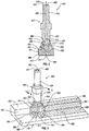
FIG. 3 is a schematic, perspective view of the brush ofFIG. 1 , delivering glutinous substance to a workpiece; -
FIG. 4 is a schematic, cross-sectional side elevation view of the brush ofFIG. 1 , delivering glutinous substance to a workpiece; -
FIG. 5 is a schematic, cross-sectional side elevation view of the brush ofFIG. 1 ; -
FIG. 6 is a schematic, cross-sectional side elevation view of the brush ofFIG. 1 ; -
FIG. 7 is a schematic, perspective view of the brush ofFIG. 1 , delivering glutinous substance to a workpiece; -
FIG. 8 is a schematic, perspective view of the brush ofFIG. 1 ; -
FIG. 9 is a schematic, cross-sectional side elevation view of the brush ofFIG. 1 ; -
FIG. 10 is a schematic, bottom plan view of the brush ofFIG. 1 ; -
FIG. 11 is a schematic, perspective view of the brush ofFIG. 1 ; -
FIG. 12 is a schematic, perspective view of the brush ofFIG. 1 ; -
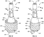
FIG. 13 is a schematic, perspective view of the brush ofFIG. 1 ; -
FIG. 14 is a schematic, perspective view of the brush ofFIG. 1 ; -
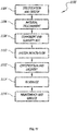
FIG. 15 is a block diagram of a method of making a brush; -
FIG. 16 is a block diagram of a method of delivering a glutinous substance to a workpiece from an end-effector; -
FIG. 17 is a block diagram of aircraft production and service methodology; and -
FIG. 18 is a schematic illustration of an aircraft. - In
FIG. 1 , referred to above, solid lines, if any, connecting various elements and/or components may represent mechanical, electrical, fluid, optical, electromagnetic and other couplings and/or combinations thereof. As used herein, "coupled" means associated directly as well as indirectly. For example, a member A may be directly associated with a member B, or may be indirectly associated therewith, e.g., via another member C. It will be understood that not all relationships among the various disclosed elements are necessarily represented. Accordingly, couplings other than those depicted in the block diagrams may also exist. Dashed lines, if any, connecting blocks designating the various elements and/or components represent couplings similar in function and purpose to those represented by solid lines; however, couplings represented by the dashed lines may either be selectively provided or may relate to alternative examples, disclosed herein. Likewise, elements and/or components, if any, represented with dashed lines, indicate alternative examples, disclosed herein. One or more elements, shown in solid and/or dashed lines, may be omitted from a particular example without departing from the scope of the present disclosure. Environmental elements, if any, are represented with dotted lines. Virtual (imaginary) elements may also be shown for clarity. Those skilled in the art will appreciate that some of the features illustrated inFIG. 1 may be combined in various ways without the need to include other features described inFIG. 1 , other drawing figures, and/or the accompanying disclosure, even though such combination or combinations are not explicitly illustrated herein. Similarly, additional features not limited to the examples presented, may be combined with some or all of the features shown and described herein. - In
FIGs. 15 ,16 , and17 , referred to above, the blocks may represent operations and/or portions thereof and lines connecting the various blocks do not imply any particular order or dependency of the operations or portions thereof. Blocks represented by dashed lines indicate alternative operations and/or portions thereof. Dashed lines, if any, connecting the various blocks represent alternative dependencies of the operations or portions thereof. It will be understood that not all dependencies among the various disclosed operations are necessarily represented.FIGs. 15 ,16 , and17 and the accompanying disclosure describing the operations of the method(s) set forth herein should not be interpreted as necessarily determining a sequence in which the operations are to be performed. Rather, although one illustrative order is indicated, it is to be understood that the sequence of the operations may be modified when appropriate. Accordingly, certain operations may be performed in a different order or simultaneously. Additionally, those skilled in the art will appreciate that not all operations described need be performed. - In the following description, numerous specific details are set forth to provide a thorough understanding of the disclosed concepts, which may be practiced without some or all of these particulars. In other instances, details of known devices and/or processes have been omitted to avoid unnecessarily obscuring the disclosure.
- Unless otherwise indicated, the terms "first," "second," etc. are used herein merely as labels, and are not intended to impose ordinal, positional, or hierarchical requirements on the items to which these terms refer. Moreover, reference to, e.g., a "second" item does not require or preclude the existence of, e.g., a "first" or lower-numbered item, and/or, e.g., a "third" or higher-numbered item.
- As used herein, a system, apparatus, structure, article, element, component, or hardware "configured to" perform a specified function is indeed capable of performing the specified function without any alteration, rather than merely having potential to perform the specified function after further modification. In other words, the system, apparatus, structure, article, element, component, or hardware "configured to" perform a specified function is specifically selected, created, implemented, utilized, programmed, and/or designed for the purpose of performing the specified function. As used herein, "configured to" denotes existing characteristics of a system, apparatus, structure, article, element, component, or hardware which enable the system, apparatus, structure, article, element, component, or hardware to perform the specified function without further modification. For purposes of this disclosure, a system, apparatus, structure, article, element, component, or hardware described as being "configured to" perform a particular function may additionally or alternatively be described as being "adapted to" and/or as being "operative to" perform that function.
- Referring generally to
FIG. 1 and particularly to, e.g.,FIGS. 2-14 ,brush 400 for deliveringglutinous substance 168 to workpiece 170 from end-effector 102 is disclosed.Brush 400 comprisesbody 402, havingrotational axis 438.Body 402 comprisesfirst end 407,second end 411, oppositefirst end 407, andchannel 408, comprisingaxial inlet 409 andoutlet 480.Axial inlet 409 is atfirst end 407 ofbody 402 and is coaxial withrotational axis 438.Brush 400 also comprisesbristles 420, extending frombody 402 so that bristles 420 are not parallel torotational axis 438 ofbody 402. -
Brush 400 is configured to facilitate ease and efficiency associated with the application of glutinous substances onto surfaces of workpieces.Axial inlet 409, being coaxial withrotational axis 438, allows flow ofglutinous substance 168 throughchannel 408 asbrush 400 rotates aboutrotational axis 438.Bristles 420, extending frombody 402 so that bristles 420 are not parallel torotational axis 438 ofbody 402, promote concurrent application ofglutinous substance 168 onto non-coplanar surfaces. -
First end 407 ofbody 402 may be a planar or a curved surface, generally perpendicular torotational axis 438. Likewise,second end 411 ofbody 402 may be a planar or a curved surface, generally perpendicular torotational axis 438. -
Body 402 can have a one-piece monolithic construction.Body 402 can be made of metal.Body 402 can have a multi-piece construction.Body 402 can include ashaft 404, configured to be coupled to end-effector 102.Shaft 404 can be made of metal. - Referring generally to
FIG. 1 and particularly to, e.g.,FIGS. 5 ,6 ,9, and 10 ,outlet 480 ofchannel 408 ofbody 402 comprisesaxial port 485, located atsecond end 411 ofbody 402.Axial port 485 is coaxial withrotational axis 438 ofbody 402. -
Axial port 485 ofoutlet 480 ofchannel 408, being coaxial withrotational axis 438 ofbody 402, promotes flow ofglutinous substance 168 fromoutlet 480 ofchannel 408 in direction coaxial withrotational axis 438 ofbody 402.Axial port 485 ofoutlet 480 ofchannel 408 can be coaxial withrotational axis 438 ofbody 402 and facilitates delivery ofglutinous substance 168 fromoutlet 480 ofchannel 408 to crown 421 ofthatch 431 orsecond tips 429 ofsecond tufts 427. - Referring generally to
FIG. 1 and particularly to, e.g.,FIGS. 2-5 and8-12 ,outlet 480 ofchannel 408 ofbody 402 compriseslateral port 482 betweenfirst end 407 ofbody 402 andsecond end 411 ofbody 402. -
Lateral port 482 ofoutlet 480 ofchannel 408, being betweenfirst end 407 ofbody 402 andsecond end 411 ofbody 402, promotes flow ofglutinous substance 168 fromoutlet 480 ofchannel 408 to portions ofbristles 420 betweencrown 421 ofthatch 431 andbase 424 ofthatch 431 or tofirst tufts 423. - Referring generally to
FIG. 1 and particularly to, e.g.,FIGS. 2-5 and8-12 ,lateral port 482 is one of oblique or perpendicular torotational axis 438 ofbody 402. -
Lateral port 482 ofoutlet 480 ofchannel 408, being one of oblique or perpendicular torotational axis 438 ofbody 402, promotes flow ofglutinous substance 168 fromoutlet 480 ofchannel 408 in a direction oblique or perpendicular torotational axis 438 ofbody 402. Directing flow ofglutinous substance 168 fromoutlet 480 ofchannel 408 in a direction oblique or perpendicular torotational axis 438 ofbody 402 helps to distributeglutinous substance 168 to radially outward extents ofbristles 420 away fromrotational axis 438. -
Outlet 480 may comprise multiplelateral ports 482. - Referring generally to
FIG. 1 and particularly to, e.g.,FIGS. 2-7 , bristles 420 are arranged intothatch 431 that comprisescrown 421, which is oppositefirst end 407 ofbody 402, andbase 424, located betweencrown 421 andfirst end 407 ofbody 402. Additionally,thatch 431 comprises frusto-conical portion 464 that originates atbase 424 ofthatch 431 andcylindrical portion 466 that terminates atcrown 421 ofthatch 431.Cylindrical portion 466 is contiguous with frusto-conical portion 464.Thatch 431 further comprisesboundary 465 between frusto-conical portion 464 andcylindrical portion 466. - Frusto-
conical portion 464 andcylindrical portion 466 ofthatch 431 facilitate delivery ofglutinous substance 168 to non-coplanar surfaces ofworkpiece 170. More specifically, in one example, frusto-conical portion 464 promotes delivery ofglutinous substance 168 tosecond surface 454 ofworkpiece 170, andcylindrical portion 466 promotes delivery ofglutinous substance 168 tofirst surface 450 andthird surface 452 ofworkpiece 170, wherethird surface 452 ofworkpiece 170 separatesfirst surface 450 ofworkpiece 170 fromsecond surface 454 ofworkpiece 170. Base is defined as a perimeter or boundary of a circular area. - Referring generally to
FIG. 1 and particularly to, e.g.,FIGS. 2-7 , frusto-conical portion 464 ofthatch 431 diverges towardcylindrical portion 466 ofthatch 431. - Divergence of frusto-
conical portion 464 ofthatch 431 towardcylindrical portion 466 ofthatch 431 allows for delivery ofglutinous substance 168 tosecond surface 454 ofworkpiece 170 whileglutinous substance 168 is being delivered tofirst surface 450 andthird surface 452 ofworkpiece 170. - Referring generally to
FIG. 1 and particularly to, e.g.,FIGS. 2-7 , a difference, in any plane perpendicular torotation axis 438 and intersectingthatch 431 andbody 402, between first radius RB ofthatch 431 and second radius RT of a portion ofbody 402, from which bristles 420 extend, increases frombase 424 ofthatch 431 in a direction alongrotational axis 438 towardcrown 421 ofthatch 431. - The increase in the difference, in any plane perpendicular to
rotation axis 438 and intersectingthatch 431 andbody 402, between first radius RB ofthatch 431 and second radius RT of a portion ofbody 402, frombase 424 ofthatch 431 in a direction alongrotational axis 438 towardcrown 421 ofthatch 431 allows for delivery ofglutinous substance 168 tofirst surface 450,second surface 454, andthird surface 452 ofworkpiece 170 while reducing potential for impact betweenbody 402 andthird surface 452 ofworkpiece 170. - Referring generally to
FIG. 1 and particularly to, e.g.,FIGS. 2 ,4, and 5 ,outlet 480 ofchannel 408 ofbody 402 compriseslateral port 482 betweenfirst end 407 ofbody 402 andsecond end 411 ofbody 402.Lateral port 482 is betweenbase 424 ofthatch 431 and crown ofthatch 431. -
Lateral port 482 ofoutlet 480 ofchannel 408, being betweenbase 424 ofthatch 431 and crown ofthatch 431, promotes flow ofglutinous substance 168 fromoutlet 480 ofchannel 408 to portions ofbristles 420 betweencrown 421 ofthatch 431 andbase 424 ofthatch 431. - Referring generally to
FIG. 1 and particularly to, e.g.,FIGS. 2 and4 ,lateral port 482 is betweenbase 424 ofthatch 431 andboundary 465. -
Lateral port 482 ofoutlet 480 ofchannel 408, being betweenbase 424 ofthatch 431 and boundary ofthatch 431, promotes flow ofglutinous substance 168 fromoutlet 480 ofchannel 408 to portions ofbristles 420 forming at least frusto-conical portion 464 ofthatch 431. - Referring generally to
FIG. 1 and particularly to, e.g.,FIG. 5 ,lateral port 482 is betweenboundary 465 andcrown 421 ofthatch 431. -
Lateral port 482 ofoutlet 480 ofchannel 408, being between boundary ofthatch 431 andcrown 421of thatch 431, promotes flow ofglutinous substance 168 fromoutlet 480 ofchannel 408 to portions ofbristles 420 forming at leastcylindrical portion 466 ofthatch 431 at locations betweenboundary 465 andcrown 421 ofthatch 431. - Referring generally to
FIG. 1 and particularly to, e.g.,FIGS. 5 ,6 ,9, and 10 ,outlet 480 ofchannel 408 ofbody 402 comprisesaxial port 485, located atsecond end 411 ofbody 402.Axial port 485 is coaxial withrotational axis 438 ofbody 402.Thatch 431 further comprisescavity 444, coaxial withrotational axis 438.Axial port 485 opens intocavity 444. -
Axial port 485 ofoutlet 480 ofchannel 408, being coaxial withrotational axis 438 ofbody 402, promotes flow ofglutinous substance 168 fromoutlet 480 ofchannel 408 in direction coaxial withrotational axis 438 ofbody 402. In one example,axial port 485 ofoutlet 480 ofchannel 408, being coaxial withrotational axis 438 ofbody 402, facilitates delivery ofglutinous substance 168 fromoutlet 480 ofchannel 408 to crown 421 ofthatch 431 orsecond tips 429 ofsecond tufts 427. -
Cavity 444 ofthatch 431 facilitates uniform distribution ofglutinous substance 168 fromoutlet 480 tothatch 431. For example,glutinous substance 168 fromoutlet 480 collects withincavity 444 ofthatch 431. Rotation ofbrush 400 urges, via centrifugal force,glutinous substance 168 withincavity 444 radially outward away fromrotational axis 438 into uniform contact withthatch 431 along a length ofthatch 431. - Referring generally to
FIG. 1 and particularly to, e.g.,FIG. 2 , a portion ofbody 402 convergently tapers towardsecond end 411 ofbody 402 at first angle θ1 torotational axis 438 ofbody 402. At least some ofbristles 420 extend frombody 402 at second angle θ2 torotational axis 438 ofbody 402. First angle θ1 and second angle θ2 are equal. - Convergently tapering the portion of
body 402 towardsecond end 411 of body facilitates an increase in the difference, in any plane perpendicular torotation axis 438 and intersectingthatch 431 andbody 402, between first radius RB ofthatch 431 and second radius RT of a portion ofbody 402, frombase 424 ofthatch 431 in a direction alongrotational axis 438 towardcrown 421 ofthatch 431. The increase in the difference between first radius RB ofthatch 431 and second radius RT of a portion ofbody 402 allows delivery ofglutinous substance 168 tosecond surface 454 andthird surface 452 ofworkpiece 170 while positioningbody 402 away fromsecond surface 454 andthird surface 452 ofworkpiece 170. First angle θ1 and second angle θ2 being equal allows the difference between first radius RB ofthatch 431 and second radius RT of a portion ofbody 402 to be proportional to first angle θ1 and second angle θ2.Body 402 includeshead 406. In some examples,head 406 ofbody 402 convergently tapers and bristles 420 extend fromsurface 410 ofhead 406 ofbody 402. - Referring generally to
FIG. 1 and particularly to, e.g.,FIG. 2 , a portion ofbody 402 convergently tapers towardsecond end 411 ofbody 402 at first angle θ1 torotational axis 438 ofbody 402. At least some ofbristles 420 extend frombody 402 at second angle θ2 torotational axis 438 ofbody 402. First angle θ1 and second angle θ2 are different. - As presented above, convergently tapering the portion of
body 402 towardsecond end 411 of body facilitates an increase in the difference, in any plane perpendicular torotation axis 438 and intersectingthatch 431 andbody 402, between first radius RB ofthatch 431 and second radius RT of a portion ofbody 402, frombase 424 ofthatch 431 in a direction alongrotational axis 438 towardcrown 421 ofthatch 431. First angle θ1 and second angle θ2 being different allows the difference between first radius RB ofthatch 431 and second radius RT of a portion ofbody 402 to be disproportional to first angle θ1 or second angle θ2. - Referring generally to
FIG. 1 and particularly to, e.g.,FIG. 2 , first angle θ1 is less than second angle θ2. - First angle θ1 being less than second angle θ2 promotes a large difference between first radius RB of
thatch 431 and second radius RT of a portion ofbody 402. - Referring generally to
FIGS. 1 and particularly to, e.g.,FIGS. 2-7 , a portion ofbody 402 is tapered and converges alongrotational axis 438 towardsecond end 411 ofbody 402. - Convergently tapering the portion of
body 402 towardsecond end 411 of body facilitates an increase in the difference, in any plane perpendicular torotation axis 438 and intersectingthatch 431 andbody 402, between first radius RB ofthatch 431 and second radius RT of a portion ofbody 402, frombase 424 ofthatch 431 in a direction alongrotational axis 438 towardcrown 421 ofthatch 431. - Referring generally to
FIG. 1 and particularly to, e.g.,FIGS. 2-7 ,13, and 14 , bristles 420, extending frombody 402 so that bristles 420 are not parallel torotational axis 438, are arranged intothatch 431. -
Thatch 431 ofbristles 420 promotes full and uniform coverage ofglutinous substance 168 delivered to workpiece 170 frombristles 420 ofthatch 431. - Referring generally to
FIG. 1 and particularly to, e.g.,FIGS. 8-12 , bristles 420, extending frombody 402 so that bristles 420 are not parallel torotational axis 438, are arranged intofirst tufts 423. -
First tufts 423 promote full and uniform coverage ofglutinous substance 168 delivered to workpiece 170 frombristles 420. Additionally, in some examples,first tufts 423 may facilitate ease in makingbrush 400 asfirst tufts 423 can be easier to assemble and couple tobody 402 thanthatch 431. - Referring generally to
FIG. 1 and particularly to, e.g.,FIGS. 8-12 , each offirst tufts 423 comprisesfirst tip 425, parallel torotational axis 438 ofbody 402. -
First tip 425 of each offirst tufts 423, being parallel torotational axis 438 ofbody 402 promotes delivery ofglutinous substance 168 to surfaces ofworkpiece 170, such asthird surface 452 ofworkpiece 170, parallel torotational axis 438 ofbody 402. - Referring generally to
FIG. 1 and particularly to, e.g.,FIGS. 8-12 ,first tufts 423 extend frombody 402 alongpaths 451, parallel torotational axis 438 ofbody 402. - Extending
first tufts 423 frombody 402 alongpaths 451, parallel torotational axis 438 ofbody 402, facilitates full and uniform coverage ofglutinous substance 168 delivered to workpiece 170 frombristles 420 offirst tufts 423. - Referring generally to
FIG. 1 and particularly to, e.g.,FIG. 11 ,outlet 480 ofchannel 408 ofbody 402 compriseslateral port 482 betweenfirst end 407 ofbody 402 andsecond end 411 ofbody 402.Lateral port 482 is alongside and between two ofpaths 451, along whichfirst tufts 423 extend frombody 402. -
Lateral port 482, being alongside and between two ofpaths 451 along whichfirst tufts 423 extend frombody 402, facilitates full and uniform coverage ofglutinous substance 168 delivered to workpiece 170 frombristles 420 offirst tufts 423 by allowingfirst tufts 423 to be uniformly spaced alongpaths 451. - Referring generally to
FIG. 1 and particularly to, e.g.,FIGS. 8, 9 , and12 ,outlet 480 ofchannel 408 ofbody 402 compriseslateral port 482 betweenfirst end 407 ofbody 402 andsecond end 411 ofbody 402.Lateral port 482 is between two offirst tufts 423 that extend frombody 402 along one ofpaths 451, parallel torotational axis 438 ofbody 402. -
Lateral port 482, being between two offirst tufts 423, extending frombody 402 along one ofpaths 451, parallel torotational axis 438 ofbody 402, promotes efficient delivery ofglutinous substance 168 fromlateral port 482 ofoutlet 480 tobristles 420 offirst tufts 423. - Referring generally to, e.g.,
FIG. 1 and particularly toFIGS. 8-14 ,brush 400 further comprises second bristles 432, extending, parallel torotational axis 438 ofbody 402, fromsecond end 411 ofbody 402. - Second bristles 432 promote delivery of
glutinous substance 168 to surfaces ofworkpiece 170, such asfirst surface 450 ofworkpiece 170, perpendicular torotational axis 438 ofbody 402 and facingsecond end 411 ofbody 402. - Referring generally to, e.g.,
FIG. 1 and particularly toFIGS. 8-11 and14 , second bristles 432, extending, parallel torotational axis 438 ofbody 402, fromsecond end 411 ofbody 402, are arranged intosecond tufts 427. -
Second tufts 427 promote full and uniform coverage ofglutinous substance 168 delivered to workpiece 170 frombristles 420. Additionally,second tufts 427 may facilitate ease in makingbrush 400. - Referring generally to, e.g.,
FIG. 1 and particularly toFIGS. 8-11 and14 , each ofsecond tufts 427 comprisessecond tip 429, perpendicular torotational axis 438 ofbody 402. -
Second tip 429 of each ofsecond tufts 427, being perpendicular torotational axis 438 ofbody 402, promotes delivery ofglutinous substance 168 to surfaces ofworkpiece 170, such asfirst surface 450 ofworkpiece 170, perpendicular torotational axis 438 ofbody 402 and facingsecond end 411 ofbody 402. - Referring generally to, e.g.,
FIG. 1 and particularly toFIGS. 12 and13 , second bristles 432, extending, parallel torotational axis 438 ofbody 402, fromsecond end 411 ofbody 402, are arranged intothatch 431. -
Thatch 431 ofbristles 420 promotes full and uniform coverage ofglutinous substance 168 delivered to workpiece 170 frombristles 420 ofthatch 431. - Referring generally to, e.g.,
FIG. 1 and particularly toFIGS. 6 and9 , at least a portion ofchannel 408 ofbody 402 convergently tapers alongrotational axis 438 towardsecond end 411 ofbody 402.. - Convergently tapering at least a portion of
channel 408 ofbody 402 alongrotational axis 438 towardsecond end 411 ofbody 402 promotes acceleration ofglutinous substance 168 flowing through the convergently tapered portion ofchannel 408 ofbody 402. - Referring generally to, e.g.,
FIG. 1 and particularly toFIG. 13 , bristles 420 extend frombody 402 orthogonally torotational axis 438 ofbody 402. -
Bristles 420, extending frombody 402 orthogonally torotational axis 438 ofbody 402, promotes delivery ofglutinous substance 168 to surfaces ofworkpiece 170, such asthird surface 452 ofworkpiece 170, parallel torotational axis 438 ofbody 402. - Referring generally to, e.g.,
FIG. 1 and particularly toFIG. 2-9 ,11 ,12 , and14 , bristles 420 extend frombody 402 obliquely torotational axis 438 ofbody 402. -
Bristles 420, extending obliquely torotational axis 438 ofbody 402, promote delivery ofglutinous substance 168 to non-coplanar surfaces that are parallel to and separated, or offset, from each other. - Referring generally to, e.g.,
FIGS. 2-7 and14 and particularly toFIG. 15 ,method 500 of makingbrush 400 is disclosed.Method 500 comprises (block 502) attachingbristles 420 tobody 402 such that bristles 420 are not parallel torotational axis 438 ofbody 402.Body 402 comprisesfirst end 407,second end 411, oppositefirst end 407, andchannel 408, comprisingaxial inlet 409 andoutlet 480.Axial inlet 409 is atfirst end 407 ofbody 402 and is coaxial withrotational axis 438.Method 500 also comprises (block 504) removing first portions of at least a plurality ofbristles 420 to formthatch 431 that comprises frusto-conical portion 464 andcylindrical portion 466. -
Method 500 facilitates the making ofbrush 400 that is configured to facilitate ease and efficiency associated with the application of glutinous substances onto surfaces of workpieces.Axial inlet 409 being coaxial withrotational axis 438 allows flow ofglutinous substance 168 throughchannel 408 asbrush 400 rotates aboutrotational axis 438.Bristles 420, extending frombody 402 so that bristles 420 are not parallel torotational axis 438 ofbody 402, promote concurrent application ofglutinous substance 168 onto non-coplanar surfaces. Removing first portions of at least a plurality ofbristles 420 to formthatch 431 promotes ease in formingthatch 431. For example, removing first portions of at least a plurality ofbristles 420, afterbristles 420 are coupled tobody 402 and arranged inthatch 431, to form frusto-conical portion 464 andcylindrical portion 466 ofthatch 431 promotes accurate, precise, and simplified formation of frusto-conical portion 464 andcylindrical portion 466 ofthatch 431. Frusto-conical portion 464 andcylindrical portion 466 ofthatch 431 facilitate delivery ofglutinous substance 168 to non-coplanar surfaces ofworkpiece 170. More specifically, in one example, frusto-conical portion 464 promotes delivery ofglutinous substance 168 tosecond surface 454 ofworkpiece 170, andcylindrical portion 466 promotes delivery ofglutinous substance 168 tofirst surface 450 andthird surface 452 ofworkpiece 170, wherethird surface 452 ofworkpiece 170 separatesfirst surface 450 ofworkpiece 170 fromsecond surface 454 ofworkpiece 170. - Referring generally to, e.g.,
FIGS. 2-7 and14 and particularly toFIG. 15 , according tomethod 500, removing the first portions of at least the plurality ofbristles 420 comprises (block 506) burning away the first portions of at least the plurality ofbristles 420 so that second precursor portions of at least the plurality of thebristles 420 remain attached tobody 402. The second precursor portion comprises melted ends. - Burning away the first portions of at least the plurality of
bristles 420 provides an efficient, inexpensive, and labor-reducing way to remove the first portions of at least the plurality ofbristles 420 to form frusto-conical portion 464 andcylindrical portion 466 ofthatch 431. - Referring generally to, e.g.,
FIGS. 2-7 and14 and particularly toFIG. 15 , according tomethod 500, removing the first portions of at least the plurality ofbristles 420 further comprises (block 508) rubbing away the melted ends of the second precursor portions of at least the plurality ofbristles 420 using an abrasive surface. - Rubbing the melted ends of the second precursor portions of at least the plurality of
bristles 420 using the abrasive surface facilitates the precise removal of the melted ends of the second precursor portions from at least the plurality ofbristles 420. - The abrasive surface can be any of various surfaces having friction-inducing features, such as relative sharp surface undulations or protuberances. In some examples, the abrasive surface is sand paper having a grit sufficient to remove the melted ends of the second precursor portions of at least the plurality of
bristles 420. Rubbing away the melted ends of the second precursor portions of at least the plurality ofbristles 420 using the abrasive surface may include positioning the melted ends in contact with the abrasive surface, and while in contact, repeatedly moving the melted ends back and forth along the abrasive surface with enough force that only the melted ends are removed from the second precursor portions. - Referring generally to, e.g.,
FIGS. 2-7 and14 and particularly toFIG. 15 , according tomethod 500, (block 510) the first portions of at least the plurality ofbristles 420 are burned away with a laser beam. - Using a laser beam to burn away the first portions of at least the plurality of
bristles 420 promotes accurate and precise formation of frusto-conical portion 464 andcylindrical portion 466 ofthatch 431. - Referring generally to, e.g.,
FIGS. 2-7 and14 and particularly toFIG. 15 , according tomethod 500, (block 512) the first portions of at least the plurality ofbristles 420 are burned away using a heated surface. - Burning away the first portions of at least the plurality of
bristles 420 using a heated surface facilitates accurate and precise formation of frusto-conical portion 464 andcylindrical portion 466 ofthatch 431. Additionally, using a heated surface to burn away the first portions of at least the plurality ofbristles 420 promotes efficiency when forming frusto-conical portions 464 andcylindrical portions 466 ofthatches 431 ofmultiple brushes 400 in a repetitive process. - The heated surface can be a surface of any of various objects made of a thermally conductive material heated to a temperature sufficient to controllably melt or burn bristles 420. The heated surface can be made of a metal, such as steel, brass, and the like. The heated surface can be a heated surface of a branding-iron-type object.
- Referring generally to
FIG. 2-7 and14 and particularly to, e.g.,FIG. 15 , according tomethod 500, removing the first portions of at least the plurality ofbristles 420 comprises (block 514) cutting away the first portions of at least the plurality ofbristles 420. - Cutting away the first portions of at least the plurality of
bristles 420 to remove the first portions of at least the plurality ofbristles 420 promotes clean and precise removal of the first portions of at least the plurality ofbristles 420. - Referring generally to 2-7 and 14 and particularly to, e.g.,
FIG. 15 , according tomethod 500, removing the first portions of at least the plurality ofbristles 420 to formthatch 431 comprises (block 516) removing the first portions of at least the plurality ofbristles 420 along directions parallel torotational axis 438 ofbody 402.. - Removing the first portions of at least the plurality of
bristles 420 along directions parallel torotational axis 438 ofbody 402 facilitates ease in forming frusto-conical portion 464 andcylindrical portion 466 ofthatch 431. For example, bristles 420, having uniform or different lengths, can be first coupled tobody 402 at oblique angle torotational axis 438 ofbody 402, and then trimmed along directions parallel torotational axis 438 ofbody 402, circumferentially aboutthatch 431 at uniform radii fromrotational axis 438. - Referring generally to
FIG. 4 and particularly to, e.g.,FIG. 16 ,method 600 of deliveringglutinous substance 168 to workpiece 170 from end-effector 102 is disclosed.Workpiece 170 comprisesfirst surface 450,second surface 454, spaced normal distance H fromfirst surface 450, andthird surface 452, separatingfirst surface 450 fromsecond surface 454.Method 600 comprises (block 602) using end-effector 102 to rotatebrush 400 relative to workpiece 170 aboutrotational axis 438.Brush 400 comprisesbody 402, comprisingfirst end 407,second end 411, opposingfirst end 407, andchannel 408, comprisingaxial inlet 409 andoutlet 480.Axial inlet 409 is atfirst end 407 ofbody 402 and is coaxial withrotational axis 438.Brush 400 also comprisesbristles 420, extending frombody 402 so that bristles 420 are not parallel torotational axis 438 ofbody 402.Bristles 420 are arranged intothatch 431, comprising frusto-conical portion 464,cylindrical portion 466,boundary 465 between frusto-conical portion 464 andcylindrical portion 466, andcrown 421, which is oppositefirst end 407 ofbody 402.Cylindrical portion 466 ofthatch 431 terminates atcrown 421 ofthatch 431. Additionally,method 600 comprises (block 604), while rotatingbrush 400 relative to workpiece 170 aboutrotational axis 438, urgingglutinous substance 168 from end-effector 102 throughchannel 408 ofbody 402 ofbrush 400 fromaxial inlet 409 ofchannel 408 tooutlet 480 ofchannel 408, into contact withthatch 431.Method 600 further comprises (block 606) using end-effector 102 to positionbrush 400 relative to workpiece 170 such thatglutinous substance 168 in contact withthatch 431 is delivered onto at leastfirst surface 450 andthird surface 452 ofworkpiece 170. -
Method 600 facilitates delivery ofglutinous substance 168 to workpiece 170 from end-effector 102 usingbrush 400 that is configured to facilitate ease and efficiency of the delivery ofglutinous substance 168 onto surfaces of workpieces.Axial inlet 409 being coaxial withrotational axis 438 allows flow ofglutinous substance 168 throughchannel 408 asbrush 400 rotates aboutrotational axis 438.Bristles 420, extending frombody 402 so that bristles 420 are not parallel torotational axis 438 ofbody 402, promote concurrent application ofglutinous substance 168 onto non-coplanar surfaces. Rotatingbrush 400 while urgingglutinous substance 168 throughchannel 408 and into contact withthatch 431 helps to uniformly deliverglutinous substance 168 tobristles 420 ofthatch 431. - Referring generally to
FIG. 4 and particularly to, e.g.,FIG. 16 ,method 600 further comprises (block 614), while rotatingbrush 400 aboutrotational axis 438 andpositioning brush 400 relative to workpiece 170 such thatglutinous substance 168 in contact withthatch 431 is delivered onto at leastfirst surface 450 andthird surface 452 ofworkpiece 170, movingbrush 400 alongworkpiece 170. - Moving
brush 400 alongworkpiece 170, while rotatingbrush 400 aboutrotational axis 438 andpositioning brush 400 relative to workpiece 170 such thatglutinous substance 168 in contact withthatch 431 is delivered onto at leastfirst surface 450 andthird surface 452 ofworkpiece 170, facilitates the delivery ofglutinous substance 168 to areas ofworkpiece 170 larger thanbrush 400. For example,brush 400 can be moved along a seam between two interconnected parts ofworkpiece 170 to deliverglutinous substance 168 along a length of the seam and a length of portions ofworkpiece 170 adjacent the seam. - Referring generally to
FIG. 4 and particularly to, e.g.,FIG. 16 , according tomethod 600, (block 608) whenglutinous substance 168 in contact withthatch 431 is delivered onto at leastfirst surface 450 andthird surface 452 ofworkpiece 170 bybristles 420,second end 411 ofbody 402 ofbrush 400 is third distance D3 fromfirst surface 450 ofworkpiece 170 alongrotational axis 438 ofbody 402 ofbrush 400. Third distance D3 is less than normal distance H betweenfirst surface 450 andsecond surface 454 ofworkpiece 170. -
Second end 411 ofbody 402 ofbrush 400, being third distance D3, which is less than normal distance H betweenfirst surface 450 andsecond surface 454 ofworkpiece 170, fromfirst surface 450 ofworkpiece 170 whenglutinous substance 168 in contact withthatch 431 is delivered onto at leastfirst surface 450 andthird surface 452 ofworkpiece 170 bybristles 420, promotes accurate and quality deliverance ofglutinous substance 168 onto at leastfirst surface 450 andthird surface 452. - Referring generally to
FIG. 4 and particularly to, e.g.,FIG. 16 , according tomethod 600, (block 610) whenglutinous substance 168 in contact withthatch 431 is delivered onto onlyfirst surface 450 andthird surface 452 ofworkpiece 170 bybristles 420,boundary 465 between frusto-conical portion 464 andcylindrical portion 466 ofthatch 431 is second distance D2 fromfirst surface 450 ofworkpiece 170 alongrotational axis 438 ofbody 402 ofbrush 400. Second distance D2 is less than normal distance H betweenfirst surface 450 andsecond surface 454 ofworkpiece 170. - Positioning
brush 400 relative to workpiece 170 such that second distance D2 is less than normal distance H betweenfirst surface 450 andsecond surface 454 ofworkpiece 170 facilitates positioning tips of allbristles 420 ofthatch 431 belowsecond surface 454 ofworkpiece 170. With tips ofbristles 420 ofthatch 431 belowsecond surface 454 ofworkpiece 170, delivery ofglutinous substance 168 ontosecond surface 454 ofworkpiece 170 is prevented. - Referring generally to
FIG. 4 and particularly to, e.g.,FIG. 16 , according tomethod 600, (block 612) whenglutinous substance 168 in contact withthatch 431 is delivered ontofirst surface 450,second surface 454, andthird surface 452 of workpiece bybristles 420,boundary 465 between frusto-conical portion 464 andcylindrical portion 466 ofthatch 431 is second distance D2 fromfirst surface 450 ofworkpiece 170 alongrotational axis 438 ofbody 402 ofbrush 400. Second distance D2 is greater than normal distance H betweenfirst surface 450 andsecond surface 454 ofworkpiece 170. - Positioning
brush 400 relative to workpiece 170 such that second distance D2 is greater than normal distance H betweenfirst surface 450 andsecond surface 454 ofworkpiece 170 facilitates positioning tips of at least somebristles 420 ofthatch 431 abovesecond surface 454 ofworkpiece 170. With tips of somebristles 420 ofthatch 431 abovesecond surface 454 ofworkpiece 170, delivery ofglutinous substance 168 ontosecond surface 454 ofworkpiece 170 is provided. - Examples, disclosed herein, may be described in the context of aircraft manufacturing and
service method 1100 as shown inFIG. 17 andaircraft 1102 as shown inFIG. 18 . During pre-production,illustrative method 1100 may include specification and design (block 1104) ofaircraft 1102 and material procurement (block 1106). During production, component and subassembly manufacturing (block 1108) and system integration (block 1110) ofaircraft 1102 may take place. Thereafter,aircraft 1102 may go through certification and delivery (block 1112) to be placed in service (block 1114). While in service,aircraft 1102 may be scheduled for routine maintenance and service (block 1116). Routine maintenance and service may include modification, reconfiguration, refurbishment, etc. of one or more systems ofaircraft 1102. - Each of the processes of
illustrative method 1100 may be performed or carried out by a system integrator, a third party, and/or an operator (e.g., a customer). For the purposes of this description, a system integrator may include, without limitation, any number of aircraft manufacturers and major-system subcontractors; a third party may include, without limitation, any number of vendors, subcontractors, and suppliers; and an operator may be an airline, leasing company, military entity, service organization, and so on. - As shown in
FIG.18 ,aircraft 1102 produced byillustrative method 1100 may includeairframe 1118 with a plurality of high-level systems 1120 and interior 1122. Examples of high-level systems 1120 include one or more ofpropulsion system 1124,electrical system 1126,hydraulic system 1128, andenvironmental system 1130. Any number of other systems may be included. Although an aerospace example is shown, the principles disclosed herein may be applied to other industries, such as the automotive industry. Accordingly, in addition toaircraft 1102, the principles disclosed herein may apply to other vehicles, e.g., land vehicles, marine vehicles, space vehicles, etc. - Apparatus(es) and method(s) shown or described herein may be employed during any one or more of the stages of the related manufacturing and
service method 1100. For example, components or subassemblies corresponding to component and subassembly manufacturing (block 1108) may be fabricated or manufactured in a manner similar to components or subassemblies produced whileaircraft 1102 is in service (block 1114). Also, one or more examples of the apparatus(es), method(s), or combination thereof may be utilized duringproduction stages aircraft 1102. Similarly, one or more examples of the apparatus or method realizations, or a combination thereof, may be utilized, for example and without limitation, whileaircraft 1102 is in service (block 1114) and/or during maintenance and service (block 1116). - Different examples of the apparatus(es) and method(s) disclosed herein include a variety of components, features, and functionalities. It should be understood that the various examples of the apparatus(es) and method(s) disclosed herein may include any of the components, features, and functionalities of any of the other examples of the apparatus(es) and method(s) disclosed herein in any combination, and all of such possibilities are intended to be within the scope of the present disclosure.
- Many modifications of examples set forth herein will come to mind to one skilled in the art to which the present disclosure pertains having the benefit of the teachings presented in the foregoing descriptions and the associated drawings.
- Therefore, it is to be understood that the present disclosure is not to be limited to the specific examples illustrated and that modifications and other examples are intended to be included within the scope of the appended claims. Moreover, although the foregoing description and the associated drawings describe examples, disclosed herein in the context of certain illustrative combinations of elements and/or functions, it should be appreciated that different combinations of elements and/or functions may be provided by alternative implementations without departing from the scope of the appended claims. Accordingly, parenthetical reference numerals in the appended claims are presented for illustrative purposes only and are not intended to limit the scope of the claimed subject matter to the specific examples, disclosed herein.
Claims (15)
- A method (500) of making a brush (400), the method comprising steps of:attaching bristles (420) to a body (402) such that the bristles (420) are not parallel to a rotational axis (438) of the body (402), wherein:the body (402) comprises a first end (407), a second end (411), opposite the first end (407), and a channel (408), comprising an axial inlet (409) and an outlet (480); andthe axial inlet (409) is at the first end (407) of the body (402) and is coaxial with the rotational axis (438); andremoving first portions of at least a plurality of the bristles (420) to form a thatch (431), comprising a frusto-conical portion (464) and a cylindrical portion (466).
- The method according to claim 1, wherein the step of removing the first portions of at least the plurality of bristles (420) to form the thatch (431) comprises burning away the first portions of at least the plurality of bristles (420) so that second precursor portions of at least the plurality of the bristles (420) remain attached to the body (402).
- The method according to claim 2, wherein ends of the second precursor portions of at least the plurality of the bristles (420) are melted.
- The method according to claim 3, further comprising a step of rubbing away the melted ends of the second precursor portions of at least the plurality of the bristles (420) using an abrasive surface.
- The method according to claims 4, wherein the abrasive surface comprises friction-inducing features.
- The method according to claim 5, wherein the friction-inducing features comprise relatively sharp surface undulations or protuberances.
- The method according to any one of claims 4 to 6, wherein the abrasive surface is sand paper.
- The method according to any one of claims 4 to 7, wherein the step of rubbing away the melted ends of the second precursor portions of at least the plurality of the bristles (420) using the abrasive surface comprises:positioning the melted ends in contact with the abrasive surface; andrepeatedly moving the melted ends back and forth along the abrasive surface with a force, sufficient to remove only the melted ends from the second precursor portions.
- The method according to any one of claims 2 to 8, wherein the first portions of at least the plurality of bristles (420) are burned away with a laser beam.
- The method according to any one of claims 2 to 8, wherein the first portions of at least the plurality of bristles (420) are burned away using a heated surface.
- The method according to claim 10, wherein the heated surface is a surface of an object made of a thermally conductive material.
- The method according to claim 11, wherein the heated surface is made of a metal, such as steel, brass, and the like, preferably wherein the heated surface is a heated surface of a branding-iron-type object.
- The method according to claim 1, wherein the step of removing the first portions of at least the plurality of bristles (420) to form the thatch (431) comprises cutting away the first portions of at least the plurality of bristles (420).
- The method according to any one of the preceding claims, wherein the step of removing the first portions of at least the plurality of bristles (420) to form the thatch (431) comprises removing the first portions of at least the plurality of bristles (420) along directions parallel to rotational axis (438) of body (402).
- The method according to any one of the preceding claims, wherein bristles (420), having uniform or different lengths, are firstly coupled to the body (402) at an oblique angle to the rotational axis (438) of the body (402), and then trimmed along directions parallel to the rotational axis (438) of the body (402), circumferentially about the thatch (431) at uniform radii from the rotational axis (438).
Applications Claiming Priority (3)
| Application Number | Priority Date | Filing Date | Title |
|---|---|---|---|
| US201562242216P | 2015-10-15 | 2015-10-15 | |
| US15/143,172 US10524562B2 (en) | 2015-10-15 | 2016-04-29 | Brushes for delivering glutinous substance to workpiece from end-effector |
| EP16193055.7A EP3155928B1 (en) | 2015-10-15 | 2016-10-10 | Brushes for delivering glutinous substance to workpiece from end-effector and methods for making and using the same |
Related Parent Applications (1)
| Application Number | Title | Priority Date | Filing Date |
|---|---|---|---|
| EP16193055.7A Division EP3155928B1 (en) | 2015-10-15 | 2016-10-10 | Brushes for delivering glutinous substance to workpiece from end-effector and methods for making and using the same |
Publications (1)
| Publication Number | Publication Date |
|---|---|
| EP3701833A1 true EP3701833A1 (en) | 2020-09-02 |
Family
ID=58335162
Family Applications (2)
| Application Number | Title | Priority Date | Filing Date |
|---|---|---|---|
| EP20168265.5A Pending EP3701833A1 (en) | 2015-10-15 | 2016-10-10 | Methods for making brushes for delivering glutinous substance to workpiece |
| EP16193055.7A Active EP3155928B1 (en) | 2015-10-15 | 2016-10-10 | Brushes for delivering glutinous substance to workpiece from end-effector and methods for making and using the same |
Family Applications After (1)
| Application Number | Title | Priority Date | Filing Date |
|---|---|---|---|
| EP16193055.7A Active EP3155928B1 (en) | 2015-10-15 | 2016-10-10 | Brushes for delivering glutinous substance to workpiece from end-effector and methods for making and using the same |
Country Status (6)
| Country | Link |
|---|---|
| US (2) | US10524562B2 (en) |
| EP (2) | EP3701833A1 (en) |
| JP (2) | JP6879707B2 (en) |
| CN (1) | CN106903024B (en) |
| BR (1) | BR102016023781B1 (en) |
| CA (1) | CA2945362C (en) |
Families Citing this family (11)
| Publication number | Priority date | Publication date | Assignee | Title |
|---|---|---|---|---|
| US10441067B2 (en) | 2015-10-15 | 2019-10-15 | The Boeing Company | Brushes for delivering glutinous substance to workpiece from end-effector |
| US10518289B2 (en) | 2015-10-15 | 2019-12-31 | The Boeing Company | Apparatuses for applying glutinous substances |
| US10524562B2 (en) | 2015-10-15 | 2020-01-07 | The Boeing Company | Brushes for delivering glutinous substance to workpiece from end-effector |
| JP7091076B2 (en) * | 2018-01-25 | 2022-06-27 | 株式会社Screenホールディングス | Board cleaning brush and board cleaning device |
| BR102018008935B1 (en) * | 2018-05-03 | 2021-09-28 | Petróleo Brasileiro S.A. - Petrobras | CLEANING AND POLISHING DEVICE FOR SUBSEA EQUIPMENT CONNECTIONS |
| US11135612B2 (en) * | 2019-03-19 | 2021-10-05 | The Boeing Company | Rotating applicators having fluid dispensers |
| US11130146B2 (en) * | 2019-05-21 | 2021-09-28 | The Boeing Company | Fastener-coating tools |
| CN110773374B (en) * | 2019-10-30 | 2021-06-15 | 绍兴艾弗笛尼智能科技有限公司 | Apparatus for continuous surface treatment of metal components against corrosion |
| CN111530705B (en) * | 2019-12-24 | 2021-07-06 | 中国航空工业集团公司北京航空精密机械研究所 | Be used for gummed mechanism of honeycomb section bar honeycomb inner wall |
| WO2024040056A1 (en) * | 2022-08-19 | 2024-02-22 | Illinois Tool Works Inc. | Systems and methods of forming a brush to clean a surface |
| US12458998B2 (en) | 2023-05-31 | 2025-11-04 | The Boeing Company | Dauber assemblies |
Citations (4)
| Publication number | Priority date | Publication date | Assignee | Title |
|---|---|---|---|---|
| EP0444436A2 (en) * | 1990-03-01 | 1991-09-04 | CORONET-Werke Gesellschaft mit beschränkter Haftung | Treatment of bristles |
| EP0925741A2 (en) * | 1997-12-17 | 1999-06-30 | Color Access, Inc. | Laser cutting of brushes |
| WO2003070051A1 (en) * | 2002-02-25 | 2003-08-28 | Coty Sa | Method of cutting bristles of a cosmetic applicator brush, guide tube and implementing machine, and corresponding brush, applicator system and cosmetic product. |
| EP2842457A1 (en) * | 2013-09-03 | 2015-03-04 | The Boeing Company | Tool for applying a fluid |
Family Cites Families (43)
| Publication number | Priority date | Publication date | Assignee | Title |
|---|---|---|---|---|
| US1330001A (en) | 1920-02-03 | Automatic painting-machine | ||
| US1314441A (en) * | 1919-08-26 | Brush | ||
| US1199780A (en) * | 1915-10-20 | 1916-10-03 | Ralph B Goodrich | Rotary brush. |
| US1475079A (en) * | 1920-06-08 | 1923-11-20 | Miller Fred William | Rotary brush |
| US1465856A (en) | 1922-03-16 | 1923-08-21 | Charles B Harrison | Paintbrush |
| US1979240A (en) * | 1931-05-05 | 1934-11-06 | Ham Boiler Corp | Brush for a washing machine |
| US2064318A (en) | 1935-03-06 | 1936-12-15 | Us Mfg Corp | Fountain brush |
| US2227792A (en) | 1938-02-19 | 1941-01-07 | Norton Auto Flow Brush Corp | Brush |
| US2321961A (en) | 1941-04-21 | 1943-06-15 | James M Wilde | Pan greasing brush |
| US2590977A (en) | 1947-01-13 | 1952-04-01 | Gordon E Kay | Finger held double-faced shoe wax applicator and polisher |
| US2747217A (en) | 1952-10-31 | 1956-05-29 | Hoover Co | Combination dusting brush |
| US2859564A (en) | 1955-03-22 | 1958-11-11 | Reid Brothers Company Inc | Machine tool |
| DE1530554C2 (en) * | 1964-05-15 | 1979-06-21 | Doelitzsch Heinz | Washing device for vehicles, in particular motor vehicles |
| CH566824A5 (en) | 1972-05-10 | 1975-09-30 | Battelle Memorial Institute | |
| US3872533A (en) * | 1972-05-17 | 1975-03-25 | Lester M Proffit | Swimming pool cleaner with rotary scrubbing action |
| US3994041A (en) * | 1975-05-19 | 1976-11-30 | The Allen Group Inc. | Vehicle washing and drying apparatus |
| CH647709A5 (en) | 1982-07-06 | 1985-02-15 | Willemin Machines Sa | Machine tool with an automatic tool changer |
| US4570282A (en) | 1982-09-27 | 1986-02-18 | Kaufman Martin H | Toothbrush |
| DE3320598C2 (en) | 1983-06-08 | 1986-10-16 | Werner und Kolb Werkzeugmaschinen GmbH, 1000 Berlin | Machine tool with a device for removing machining residues |
| DE3634018A1 (en) | 1986-10-06 | 1988-04-14 | Siemens Ag | TOOL CHANGE SYSTEM FOR AN INDUSTRIAL ROBOT |
| CN87201146U (en) * | 1987-03-21 | 1988-01-27 | 谢孝才 | Electrical painter |
| US4881289A (en) | 1988-04-27 | 1989-11-21 | Sunstar Engineering Inc. | Paint-coating brush |
| ES2079029T3 (en) | 1990-03-28 | 1996-01-01 | Usm Espana Sa | MANAGEMENT OF COMPOSITIONS OF MULTIPLE COMPONENTS. |
| US5027463A (en) | 1990-05-07 | 1991-07-02 | Daub Craig C | Toothbrush |
| FR2772573B1 (en) | 1997-12-18 | 2000-03-10 | Manuf Ind Nouvelle Elements Sa | FOLDABLE UNDER SINK FURNITURE |
| EP1112812A3 (en) | 1999-12-27 | 2003-10-15 | Nippei Toyama Corporation | Grinding spindle with dual tool mounting means |
| JP2001353611A (en) | 2000-06-14 | 2001-12-25 | Nissan Motor Co Ltd | Milling tools |
| US6409103B1 (en) | 2000-10-24 | 2002-06-25 | 360 Enterprises | 360° rotational directional nozzle for trigger sprayers |
| CA2515848A1 (en) | 2003-02-13 | 2004-09-02 | Black & Decker Inc. | Hand held scrubbing tool |
| JP3887345B2 (en) | 2003-04-17 | 2007-02-28 | 矢崎総業株式会社 | Electric wire coloring apparatus and electric wire coloring method |
| DE202004002905U1 (en) | 2003-09-08 | 2004-04-29 | ProFin Prograssive Finish AG | Tool for processing surfaces, edge areas and contours |
| US7386911B2 (en) | 2004-11-11 | 2008-06-17 | Ford Motor Company | Apparatus for dislodging and removing contaminants from a surface of a machine tool |
| US20070050938A1 (en) * | 2005-02-25 | 2007-03-08 | Euro-Pro Operating Llc | Steam cleaner and steam cleaner nozzle attachment |
| US20090080964A1 (en) | 2006-06-01 | 2009-03-26 | Castellana Jerry D | Powered painting system |
| DE102006050722A1 (en) | 2006-10-24 | 2008-04-30 | Mechanik Center Erlangen Gmbh | brush tool |
| KR20090013973A (en) * | 2007-08-03 | 2009-02-06 | 남궁금자 | Cleaning device |
| DE102008014358B4 (en) | 2008-03-14 | 2016-03-10 | Kiesling Maschinentechnik Gmbh | Machining center for processing plate-shaped or formed from plates workpieces |
| DE102008039804A1 (en) | 2008-08-14 | 2010-02-18 | Alfred Kärcher Gmbh & Co. Kg | washing brush |
| US8651046B1 (en) | 2010-07-23 | 2014-02-18 | The Boeing Company | Robotic sealant and end effector |
| US10524562B2 (en) | 2015-10-15 | 2020-01-07 | The Boeing Company | Brushes for delivering glutinous substance to workpiece from end-effector |
| US10441067B2 (en) | 2015-10-15 | 2019-10-15 | The Boeing Company | Brushes for delivering glutinous substance to workpiece from end-effector |
| US10518289B2 (en) | 2015-10-15 | 2019-12-31 | The Boeing Company | Apparatuses for applying glutinous substances |
| JP2019107747A (en) | 2017-12-19 | 2019-07-04 | Dgshape株式会社 | Processing device and method for storage of brush-shaped tool in processing device |
-
2016
- 2016-04-29 US US15/143,172 patent/US10524562B2/en active Active
- 2016-10-10 EP EP20168265.5A patent/EP3701833A1/en active Pending
- 2016-10-10 EP EP16193055.7A patent/EP3155928B1/en active Active
- 2016-10-11 JP JP2016199905A patent/JP6879707B2/en active Active
- 2016-10-11 CN CN201610885791.XA patent/CN106903024B/en active Active
- 2016-10-13 BR BR102016023781-5A patent/BR102016023781B1/en active IP Right Grant
- 2016-10-14 CA CA2945362A patent/CA2945362C/en active Active
-
2019
- 2019-11-26 US US16/696,914 patent/US11129467B2/en active Active
-
2021
- 2021-04-30 JP JP2021077362A patent/JP2021118902A/en active Pending
Patent Citations (4)
| Publication number | Priority date | Publication date | Assignee | Title |
|---|---|---|---|---|
| EP0444436A2 (en) * | 1990-03-01 | 1991-09-04 | CORONET-Werke Gesellschaft mit beschränkter Haftung | Treatment of bristles |
| EP0925741A2 (en) * | 1997-12-17 | 1999-06-30 | Color Access, Inc. | Laser cutting of brushes |
| WO2003070051A1 (en) * | 2002-02-25 | 2003-08-28 | Coty Sa | Method of cutting bristles of a cosmetic applicator brush, guide tube and implementing machine, and corresponding brush, applicator system and cosmetic product. |
| EP2842457A1 (en) * | 2013-09-03 | 2015-03-04 | The Boeing Company | Tool for applying a fluid |
Also Published As
| Publication number | Publication date |
|---|---|
| EP3155928B1 (en) | 2020-05-06 |
| CN106903024B (en) | 2020-08-07 |
| US20200093250A1 (en) | 2020-03-26 |
| US11129467B2 (en) | 2021-09-28 |
| BR102016023781B1 (en) | 2022-01-11 |
| CA2945362A1 (en) | 2017-04-15 |
| BR102016023781A2 (en) | 2017-04-25 |
| EP3155928A1 (en) | 2017-04-19 |
| CN106903024A (en) | 2017-06-30 |
| CA2945362C (en) | 2021-06-01 |
| JP2021118902A (en) | 2021-08-12 |
| JP6879707B2 (en) | 2021-06-02 |
| US20170105513A1 (en) | 2017-04-20 |
| JP2017080399A (en) | 2017-05-18 |
| US10524562B2 (en) | 2020-01-07 |
Similar Documents
| Publication | Publication Date | Title |
|---|---|---|
| US11129467B2 (en) | Brushes for delivering glutinous substance to workpiece from end-effector and methods for making and using the same | |
| US9937516B2 (en) | Brushes for delivering glutinous substance to workpiece from end-effector and methods for making the same | |
| US11172756B2 (en) | Brushes for delivering glutinous substance to workpiece from end-effector and methods for using the same | |
| EP2898970B1 (en) | Cutting tool and method for forming an opening in a stack | |
| CA2991830A1 (en) | Fluid-fed vacuum cutters | |
| CN104369084A (en) | Apparatus, system and method for aero-contouring a surface of an aerodynamically functional coating | |
| US20190143364A1 (en) | Sealant-applicator tip and method for applying a sealant material | |
| EP3375535B1 (en) | Reusable applicator and related method | |
| US10661298B2 (en) | Reusable applicators and related methods | |
| US20250108444A1 (en) | Reverse countersink cutting assemblies, reverse countersinking assemblies and methods for reverse countersinking a through hole in a workpiece | |
| CN110732779A (en) | Fixed-axis rotating laser shot blasting method for blisk stable constraint layers | |
| CN104890232A (en) | Column system module of digital processing machine and digital processing machine assembled with column system module |
Legal Events
| Date | Code | Title | Description |
|---|---|---|---|
| PUAI | Public reference made under article 153(3) epc to a published international application that has entered the european phase |
Free format text: ORIGINAL CODE: 0009012 |
|
| STAA | Information on the status of an ep patent application or granted ep patent |
Free format text: STATUS: THE APPLICATION HAS BEEN PUBLISHED |
|
| AC | Divisional application: reference to earlier application |
Ref document number: 3155928 Country of ref document: EP Kind code of ref document: P |
|
| AK | Designated contracting states |
Kind code of ref document: A1 Designated state(s): AL AT BE BG CH CY CZ DE DK EE ES FI FR GB GR HR HU IE IS IT LI LT LU LV MC MK MT NL NO PL PT RO RS SE SI SK SM TR |
|
| STAA | Information on the status of an ep patent application or granted ep patent |
Free format text: STATUS: REQUEST FOR EXAMINATION WAS MADE |
|
| 17P | Request for examination filed |
Effective date: 20210227 |
|
| RBV | Designated contracting states (corrected) |
Designated state(s): AL AT BE BG CH CY CZ DE DK EE ES FI FR GB GR HR HU IE IS IT LI LT LU LV MC MK MT NL NO PL PT RO RS SE SI SK SM TR |
|
| RAP3 | Party data changed (applicant data changed or rights of an application transferred) |
Owner name: THE BOEING COMPANY |
|
| STAA | Information on the status of an ep patent application or granted ep patent |
Free format text: STATUS: EXAMINATION IS IN PROGRESS |
|
| 17Q | First examination report despatched |
Effective date: 20250623 |