EP3701723B1 - Image data encoding and decoding - Google Patents
Image data encoding and decoding Download PDFInfo
- Publication number
- EP3701723B1 EP3701723B1 EP18797036.3A EP18797036A EP3701723B1 EP 3701723 B1 EP3701723 B1 EP 3701723B1 EP 18797036 A EP18797036 A EP 18797036A EP 3701723 B1 EP3701723 B1 EP 3701723B1
- Authority
- EP
- European Patent Office
- Prior art keywords
- samples
- reference samples
- image
- prediction
- current
- Prior art date
- Legal status (The legal status is an assumption and is not a legal conclusion. Google has not performed a legal analysis and makes no representation as to the accuracy of the status listed.)
- Active
Links
Images


Classifications
-
- H—ELECTRICITY
- H04—ELECTRIC COMMUNICATION TECHNIQUE
- H04N—PICTORIAL COMMUNICATION, e.g. TELEVISION
- H04N19/00—Methods or arrangements for coding, decoding, compressing or decompressing digital video signals
- H04N19/10—Methods or arrangements for coding, decoding, compressing or decompressing digital video signals using adaptive coding
- H04N19/102—Methods or arrangements for coding, decoding, compressing or decompressing digital video signals using adaptive coding characterised by the element, parameter or selection affected or controlled by the adaptive coding
- H04N19/103—Selection of coding mode or of prediction mode
- H04N19/105—Selection of the reference unit for prediction within a chosen coding or prediction mode, e.g. adaptive choice of position and number of pixels used for prediction
-
- H—ELECTRICITY
- H04—ELECTRIC COMMUNICATION TECHNIQUE
- H04N—PICTORIAL COMMUNICATION, e.g. TELEVISION
- H04N19/00—Methods or arrangements for coding, decoding, compressing or decompressing digital video signals
- H04N19/10—Methods or arrangements for coding, decoding, compressing or decompressing digital video signals using adaptive coding
- H04N19/102—Methods or arrangements for coding, decoding, compressing or decompressing digital video signals using adaptive coding characterised by the element, parameter or selection affected or controlled by the adaptive coding
- H04N19/103—Selection of coding mode or of prediction mode
- H04N19/11—Selection of coding mode or of prediction mode among a plurality of spatial predictive coding modes
-
- H—ELECTRICITY
- H04—ELECTRIC COMMUNICATION TECHNIQUE
- H04N—PICTORIAL COMMUNICATION, e.g. TELEVISION
- H04N19/00—Methods or arrangements for coding, decoding, compressing or decompressing digital video signals
- H04N19/10—Methods or arrangements for coding, decoding, compressing or decompressing digital video signals using adaptive coding
- H04N19/134—Methods or arrangements for coding, decoding, compressing or decompressing digital video signals using adaptive coding characterised by the element, parameter or criterion affecting or controlling the adaptive coding
- H04N19/136—Incoming video signal characteristics or properties
- H04N19/14—Coding unit complexity, e.g. amount of activity or edge presence estimation
-
- H—ELECTRICITY
- H04—ELECTRIC COMMUNICATION TECHNIQUE
- H04N—PICTORIAL COMMUNICATION, e.g. TELEVISION
- H04N19/00—Methods or arrangements for coding, decoding, compressing or decompressing digital video signals
- H04N19/10—Methods or arrangements for coding, decoding, compressing or decompressing digital video signals using adaptive coding
- H04N19/134—Methods or arrangements for coding, decoding, compressing or decompressing digital video signals using adaptive coding characterised by the element, parameter or criterion affecting or controlling the adaptive coding
- H04N19/157—Assigned coding mode, i.e. the coding mode being predefined or preselected to be further used for selection of another element or parameter
- H04N19/159—Prediction type, e.g. intra-frame, inter-frame or bidirectional frame prediction
-
- H—ELECTRICITY
- H04—ELECTRIC COMMUNICATION TECHNIQUE
- H04N—PICTORIAL COMMUNICATION, e.g. TELEVISION
- H04N19/00—Methods or arrangements for coding, decoding, compressing or decompressing digital video signals
- H04N19/10—Methods or arrangements for coding, decoding, compressing or decompressing digital video signals using adaptive coding
- H04N19/134—Methods or arrangements for coding, decoding, compressing or decompressing digital video signals using adaptive coding characterised by the element, parameter or criterion affecting or controlling the adaptive coding
- H04N19/167—Position within a video image, e.g. region of interest [ROI]
-
- H—ELECTRICITY
- H04—ELECTRIC COMMUNICATION TECHNIQUE
- H04N—PICTORIAL COMMUNICATION, e.g. TELEVISION
- H04N19/00—Methods or arrangements for coding, decoding, compressing or decompressing digital video signals
- H04N19/10—Methods or arrangements for coding, decoding, compressing or decompressing digital video signals using adaptive coding
- H04N19/169—Methods or arrangements for coding, decoding, compressing or decompressing digital video signals using adaptive coding characterised by the coding unit, i.e. the structural portion or semantic portion of the video signal being the object or the subject of the adaptive coding
- H04N19/17—Methods or arrangements for coding, decoding, compressing or decompressing digital video signals using adaptive coding characterised by the coding unit, i.e. the structural portion or semantic portion of the video signal being the object or the subject of the adaptive coding the unit being an image region, e.g. an object
- H04N19/176—Methods or arrangements for coding, decoding, compressing or decompressing digital video signals using adaptive coding characterised by the coding unit, i.e. the structural portion or semantic portion of the video signal being the object or the subject of the adaptive coding the unit being an image region, e.g. an object the region being a block, e.g. a macroblock
-
- H—ELECTRICITY
- H04—ELECTRIC COMMUNICATION TECHNIQUE
- H04N—PICTORIAL COMMUNICATION, e.g. TELEVISION
- H04N19/00—Methods or arrangements for coding, decoding, compressing or decompressing digital video signals
- H04N19/10—Methods or arrangements for coding, decoding, compressing or decompressing digital video signals using adaptive coding
- H04N19/189—Methods or arrangements for coding, decoding, compressing or decompressing digital video signals using adaptive coding characterised by the adaptation method, adaptation tool or adaptation type used for the adaptive coding
- H04N19/196—Methods or arrangements for coding, decoding, compressing or decompressing digital video signals using adaptive coding characterised by the adaptation method, adaptation tool or adaptation type used for the adaptive coding being specially adapted for the computation of encoding parameters, e.g. by averaging previously computed encoding parameters
-
- H—ELECTRICITY
- H04—ELECTRIC COMMUNICATION TECHNIQUE
- H04N—PICTORIAL COMMUNICATION, e.g. TELEVISION
- H04N19/00—Methods or arrangements for coding, decoding, compressing or decompressing digital video signals
- H04N19/44—Decoders specially adapted therefor, e.g. video decoders which are asymmetric with respect to the encoder
- H04N19/45—Decoders specially adapted therefor, e.g. video decoders which are asymmetric with respect to the encoder performing compensation of the inverse transform mismatch, e.g. Inverse Discrete Cosine Transform [IDCT] mismatch
-
- H—ELECTRICITY
- H04—ELECTRIC COMMUNICATION TECHNIQUE
- H04N—PICTORIAL COMMUNICATION, e.g. TELEVISION
- H04N19/00—Methods or arrangements for coding, decoding, compressing or decompressing digital video signals
- H04N19/50—Methods or arrangements for coding, decoding, compressing or decompressing digital video signals using predictive coding
- H04N19/503—Methods or arrangements for coding, decoding, compressing or decompressing digital video signals using predictive coding involving temporal prediction
- H04N19/51—Motion estimation or motion compensation
- H04N19/513—Processing of motion vectors
-
- H—ELECTRICITY
- H04—ELECTRIC COMMUNICATION TECHNIQUE
- H04N—PICTORIAL COMMUNICATION, e.g. TELEVISION
- H04N19/00—Methods or arrangements for coding, decoding, compressing or decompressing digital video signals
- H04N19/50—Methods or arrangements for coding, decoding, compressing or decompressing digital video signals using predictive coding
- H04N19/593—Methods or arrangements for coding, decoding, compressing or decompressing digital video signals using predictive coding involving spatial prediction techniques
-
- H—ELECTRICITY
- H04—ELECTRIC COMMUNICATION TECHNIQUE
- H04N—PICTORIAL COMMUNICATION, e.g. TELEVISION
- H04N19/00—Methods or arrangements for coding, decoding, compressing or decompressing digital video signals
- H04N19/60—Methods or arrangements for coding, decoding, compressing or decompressing digital video signals using transform coding
- H04N19/625—Methods or arrangements for coding, decoding, compressing or decompressing digital video signals using transform coding using discrete cosine transform [DCT]
-
- H—ELECTRICITY
- H04—ELECTRIC COMMUNICATION TECHNIQUE
- H04N—PICTORIAL COMMUNICATION, e.g. TELEVISION
- H04N19/00—Methods or arrangements for coding, decoding, compressing or decompressing digital video signals
- H04N19/10—Methods or arrangements for coding, decoding, compressing or decompressing digital video signals using adaptive coding
- H04N19/134—Methods or arrangements for coding, decoding, compressing or decompressing digital video signals using adaptive coding characterised by the element, parameter or criterion affecting or controlling the adaptive coding
- H04N19/156—Availability of hardware or computational resources, e.g. encoding based on power-saving criteria
Definitions
- This disclosure relates to image data encoding and decoding.
- Video data encoding and decoding systems which involve transforming video data into a frequency domain representation, quantising the frequency domain coefficients and then applying some form of entropy encoding to the quantised coefficients. This can achieve compression of the video data.
- a corresponding decoding or decompression technique is applied to recover a reconstructed version of the original video data.
- coder-decoders such as those used in H.264/MPEG-4 Advanced Video Coding (AVC) achieve data compression primarily by only encoding the differences between successive video frames.
- AVC H.264/MPEG-4 Advanced Video Coding
- These codecs use a regular array of so-called macroblocks, each of which is used as a region of comparison with a corresponding macroblock in a previous video frame, and the image region within the macroblock is then encoded according to the degree of motion found between the corresponding current and previous macroblocks in the video sequence, or between neighbouring macroblocks within a single frame of the video sequence.
- High Efficiency Video Coding also known as H.265 or MPEG-H Part 2
- H.265 High Efficiency Video Coding
- MPEG-4 AVC High Efficiency Video Coding
- the present disclosure addresses or mitigates problems arising from this processing.
- Figures 1-4 are provided to give schematic illustrations of apparatus or systems making use of the compression and/or decompression apparatus to be described below in connection with embodiments of the present technology.
- Figure 1 schematically illustrates an audio/video data transmission and reception system using video data compression and decompression.
- An input audio/video signal 10 is supplied to a video data compression apparatus 20 which compresses at least the video component of the audio/video signal 10 for transmission along a transmission route 30 such as a cable, an optical fibre, a wireless link or the like.
- the compressed signal is processed by a decompression apparatus 40 to provide an output audio/video signal 50.
- a compression apparatus 60 compresses an audio/video signal for transmission along the transmission route 30 to a decompression apparatus 70.
- FIG. 2 schematically illustrates a video display system using video data decompression.
- a compressed audio/video signal 100 is processed by a decompression apparatus 110 to provide a decompressed signal which can be displayed on a display 120.
- the decompression apparatus 110 could be implemented as an integral part of the display 120, for example being provided within the same casing as the display device.
- the decompression apparatus 110 maybe provided as (for example) a so-called set top box (STB), noting that the expression "set-top” does not imply a requirement for the box to be sited in any particular orientation or position with respect to the display 120; it is simply a term used in the art to indicate a device which is connectable to a display as a peripheral device.
- STB set top box
- the signal is supplied to the entropy decoder 410 and from there to the chain of the reverse scan unit 400, the inverse quantiser 420 and the inverse transform unit 430 before being added to the output of the image predictor 320 by the adder 450.
- the decoder reconstructs a version of the residual image and then applies this (by the adder 450) to the predicted version of the image (on a block by block basis) so as to decode each block.
- the output 460 of the adder 450 forms the output decompressed video signal 480.
- further filtering may optionally be applied (for example, by a filter 560 shown in Figure 8 but omitted from Figure 7 for clarity of the higher level diagram of Figure 7 ) before the signal is output.
- Motion-compensated prediction is an example of inter-image prediction and makes use of motion information which attempts to define the source, in another adjacent or nearby image, of image detail to be encoded in the current image. Accordingly, in an ideal example, the contents of a block of image data in the predicted image can be encoded very simply as a reference (a motion vector) pointing to a corresponding block at the same or a slightly different position in an adjacent image.
- a reference a motion vector
- a motion compensated (MC) predictor 540 uses motion information such as motion vectors derived by a motion estimator 550 from the input video signal 300. Those motion vectors are applied to a processed version of the reconstructed image 460 by the motion compensated predictor 540 to generate blocks of the inter-image prediction.
- the filtered output from the filter unit 560 in fact forms the output video signal 480 when the apparatus is operating as a decompression apparatus. It is also buffered in one or more image or frame stores 570; the storage of successive images is a requirement of motion compensated prediction processing, and in particular the generation of motion vectors. To save on storage requirements, the stored images in the image stores 570 may be held in a compressed form and then decompressed for use in generating motion vectors. For this particular purpose, any known compression / decompression system may be used.
- an image to be compressed is considered as an array of blocks or regions of samples.
- the splitting of an image into such blocks or regions can be carried out by a decision tree, such as that described in Bross et al: "High Efficiency Video Coding (HEVC) text specification draft 6", JCTVC-H1003_d0 (November 2011 .
- HEVC High Efficiency Video Coding
- the resulting blocks or regions have sizes and, in some cases, shapes which, by virtue of the decision tree, can generally follow the disposition of image features within the image. This in itself can allow for an improved encoding efficiency because samples representing or following similar image features would tend to be grouped together by such an arrangement.
- square blocks or regions of different sizes are unavailable for selection.
- blocks or regions of different shapes such as rectangular blocks (for example, vertically or horizontally oriented) can be used.
- Other non-square and non-rectangular blocks are envisaged.
- the result of the division of the image into such blocks or regions is (in at least the present examples) that each sample of an image is allocated to one, and only one, such block or region.
- intra-prediction involves generating a prediction of a current block of samples from previously-encoded and decoded samples in the same image.
- Figure 9 schematically illustrates a partially encoded image 800.
- the image is being encoded from top-left to bottom-right on a block by block basis.
- An example block encoded partway through the handling of the whole image is shown as a block 810.
- a shaded region 820 above and to the left of the block 810 has already been encoded.
- the intra-image prediction of the contents of the block 810 can make use of any of the shaded area 820 but cannot make use of the unshaded area below that.
- the image is encoded on a block by block basis such that larger blocks (referred to as coding units or CUs) are encoded in an order such as the order discussed with reference to Figure 9 .
- coding units or CUs larger blocks
- each CU there is the potential (depending on the block splitting process that has taken place) for the CU to be handled as a set of two or more smaller blocks or transform units (TUs). This can give a hierarchical order of encoding so that the image is encoded on a CU by CU basis, and each CU is potentially encoded on a TU by TU basis.
- the hierarchical order of encoding (CU by CU then TU by TU) discussed above means that there may be previously encoded samples in the current CU and available to the coding of that TU which are, for example, above-right or belowleft of that TU.
- the block 810 represents a CU; as discussed above, for the purposes of intra-image prediction processing, this may be subdivided into a set of smaller units.
- An example of a current TU 830 is shown within the CU 810. More generally, the picture is split into regions or groups of samples to allow efficient coding of signalling information and transformed data. The signalling of the information may require a different tree structure of sub-divisions to that of the transform, and indeed that of the prediction information or the prediction itself. For this reason, the coding units may have a different tree structure to that of the transform blocks or regions, the prediction blocks or regions and the prediction information.
- the intra-image prediction takes into account samples coded prior to the current TU being considered, such as those above and/or to the left of the current TU.
- Source samples, from which the required samples are predicted, may be located at different positions or directions relative to the current TU.
- the mode selector 520 of an example encoder may test all combinations of available TU structures for each candidate direction and select the prediction direction and TU structure with the best compression efficiency.
- the picture may also be encoded on a "slice" basis.
- a slice is a horizontally adjacent group of CUs. But in more general terms, the entire residual image could form a slice, or a slice could be a single CU, or a slice could be a row of CUs, and so on. Slices can give some resilience to errors as they are encoded as independent units.
- the encoder and decoder states are completely reset at a slice boundary. For example, intra-prediction is not carried out across slice boundaries; slice boundaries are treated as image boundaries for this purpose.
- Figure 10 schematically illustrates a set of possible (candidate) prediction directions.
- the full set of candidate directions is available to a prediction unit.
- the directions are determined by horizontal and vertical displacement relative to a current block position, but are encoded as prediction "modes", a set of which is shown in Figure 11 .
- DC mode represents a simple arithmetic mean of the surrounding upper and left-hand samples.
- the set of directions shown in Figure 10 is just one example; in other examples, a set of (for example) 65 angular modes plus DC and planar (a full set of 67 modes) as shown schematically in Figure 12 makes up the full set. Other numbers of modes could be used.
- the systems are operable to generate a predicted block of samples according to other samples defined by the prediction direction.
- the image encoder is configured to encode data identifying the prediction direction selected for each sample or region of the image (and the image decoder is configured to detect such data).
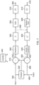
- Figure 13 schematically illustrates an intra-prediction process in which a sample 900 of a block or region 910 of samples is derived from other reference samples 920 of the same image according to a direction 930 defined by the intra-prediction mode associated with that sample.
- the reference samples 920 in this example come from blocks above and to the left of the block 910 in question and the predicted value of the sample 900 is obtained by tracking along the direction 930 to the reference samples 920.
- the direction 930 might point to a single individual reference sample but in a more general case an interpolated value between surrounding reference samples is used as the prediction value.
- the block 910 could be square as shown in Figure 13 or could be another shape such as rectangular.
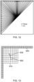
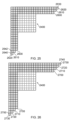
- Figures 14 and 15 schematically illustrate a previously proposed reference sample projection process.
- a block or region 1400 of samples to be predicted is surrounded by linear arrays of reference samples from which the intra prediction of the predicted samples takes place.
- the reference samples 1410 are shown as shaded blocks in Figures 14 and 15 , and the samples to be predicted are shown as unshaded blocks. Note that an 8x8 block or region of samples to be predicted is used in this example, but the techniques are applicable to variable block sizes and indeed block shapes.
- the reference sample arrays can extend beyond the extent of the block to be predicted, in order to provide for prediction modes or directions within the range indicated in Figures 10-12 . Where necessary, if previously decoded samples are not available for use as reference samples at particular reference sample positions, other reference samples can be re-used at those missing positions. Reference sample filtering processes can be used on the reference samples.
- Figure 14 relates to a projection process performed for modes which are generally to the left of the diagonal mode (18 in Figure 11 ) mainly modes 2...17
- Figure 15 schematically illustrates a reference sample projection carried for modes 19...34, namely those generally above the block to be predicted (to the right of the diagonal mode 18).
- the diagonal mode 18 can be assigned to either of these two groups as an arbitrary selection, such as to the group of modes to the right of the diagonal. So, in Figure 14 , when the current prediction mode is between modes 2 and 17 (or their equivalent in a system such as that of Figure 12 having a different number of possible prediction modes), the sample array 1420 above the current block is projected to form additional reference samples 1440 in the left hand column.
- Prediction then takes place with respect to the linear projected array 1450 formed of the original left hand column 1430 and the projected samples 1440.
- the reference samples 1500 in the left hand column are projected so as to extend to the left of the reference samples 1510 above the current block. This forms a projected array 1520.
- Figure 16 schematically illustrates a previously proposed prediction circuitry 600 arranged to carry out the projection process of Figures 14 and 15 , specifically by providing projection circuitry 1610 configured to carry out a projection process on the reference samples currently selected for a block of region to be predicted.
- the projected reference samples are stored in a buffer 1620 to be accessed by an intra predictor 1630 to generate predicted samples from the projected reference samples.
- the projection process is carried out according to the prediction mode associated with the current block to be predicted, using the techniques discussed in connection with Figures 14 and 15 .
- the same projection process is carried out in the decoder and in the encoder, so that the predicted samples are the same in each instance.
- Possible variations in operation between the use of prediction modes which will be referred to as “straight modes” and prediction modes which will be referred to as “curved modes” will now be discussed.
- Figures 17 and 18 schematically illustrate an example technique by which samples 1900 of a current region 1910 or block to be predicted, are predicted from reference samples 1920.
- the reference samples have been projected into a linear array using the techniques described with reference to Figures 14-16 above.
- a system of (x, y) coordinates is used for convenience, to allow individual reference or predicted sample positions to be identified.
- x coordinates are shown by a row 1930 of numbers
- y coordinates are shown by a column 1940 of numbers. So, each reference or predicted sample position has an associated (x, y) designation using the coordinate system.
- a generally vertical mode for example, a mode which is more vertical than horizontal 1950, such as mode 23 in the designation of Figure 11 , noting that a different mode number could be used if the set of modes shown in Figure 12 were employed, has been selected for prediction of samples 1900 of the block or region 1910.
- a generally vertical prediction mode is handled by the circuitry of Figure 16 by projecting the left column of reference samples into an extension 1960 of the reference samples above the block or region 1910.
- Each of the samples to be predicted 1900 is predicted as follows. For each sample to be predicted, there is an associated (x, y) location such as a location (0, 5) for a sample 1970 or a location (0, 4) for a sample 1972. These two samples are used purely by way of example and the same technique applies to each of the samples 1900 to be predicted.
- the sample positions of the samples 1970, 1972 to be predicted are mapped according to the direction 1950 associated with the current prediction mode to respective locations or reference positions 1974, 1976 among the reference samples.
- This mapping may be carried out using an expression such as that shown below, noting that this is a linear expression with respect to the coordinate system (x, y):
- A is an angle parameter indicating the angle of the current mode. To illustrate, for example, for a horizontal or vertical line, A would be 0; for a 45° diagonal line, A would be ⁇ 1.
- FIG. 18 A similar arrangement is shown schematically in Figure 18 , except that a generally horizontal prediction mode, for example a prediction mode which is more horizontal than vertical, such as (for example) mode 14 of the set shown in Figure 11 (or a corresponding number for a similar mode in the set shown in Figure 12 ) having a prediction direction 2000 is used.
- a generally horizontal prediction mode for example a prediction mode which is more horizontal than vertical, such as (for example) mode 14 of the set shown in Figure 11 (or a corresponding number for a similar mode in the set shown in Figure 12 ) having a prediction direction 2000 is used.
- the selection of the particular prediction mode applies to the whole of the block or region 2010 of samples 2020 to be predicted and the particular example here is chosen purely for the purposes of the present explanation.
- each row/column 2070, 2075 is used individually to generate an intermediate predicted sample value, and the intermediate predicted sample values are then combined.
- each set of reference samples comprises a set, in the respective array of reference samples, or of values interpolated from the respective array of reference samples, pointed to by the prediction direction.
- this relates to the use of the range 2100 in each row/column being aligned only with the reference position 2090 in the row/column 2070, so that the reference samples a, c and e are combined (for example, by the three-tap interpolation process) to produce a first intermediate predicted sample p1.
- the reference samples b, d and f in the row/column 2070 are combined by a similar process to produce a second intermediate predicted value p2.
- the values p1 and p2 can then be combined, for example, by an arithmetic mean or a weighted mean (for example, as discussed above, placing a greater weight such as 0.6 on the intermediate predicted sample value p2 and a reduced weight such as 0.4 on the intermediate predicted sample value p1, given that it is generated from reference samples further away from the block 2050) to generate the final predicted sample value p 2200.
- an arithmetic mean or a weighted mean for example, as discussed above, placing a greater weight such as 0.6 on the intermediate predicted sample value p2 and a reduced weight such as 0.4 on the intermediate predicted sample value p1, given that it is generated from reference samples further away from the block 2050
- the first intermediate predicted sample value p1 is generated from the reference samples c, e and g and the second intermediate predicted sample value p2 is generated from the reference samples b, d and f. As before, these can be combined by any of the processes discussed above to form the final predicted sample value p.
- the controller 343 can vary the weighting according to one or more properties or parameters of the current interpolation process.
- a parameter may be the block size of the current block to be interpolated.
- the weighting could be detected by the controller 343 from a predetermined or programmable (for example via parameter sets communicated as part of the compressed data stream) set of weight values, or derived using a predetermined or programmable function.
- a relationship is:
- the (or a) parameter may represent a spatial separation, in sample rows or columns or along the prediction direction, of the current sample to be interpolated from the nearest row/column of reference samples.
- the sample position 2065 is in the fourth column of samples to be interpolated, starting at the reference column 2070.
- the influence or contribution of a non-adjacent row or column of reference samples increases as the separation of the sample position to be predicted from that row/column increases.
- the influence of another (further away) row/column of reference samples may be expected to be lower than if the sample to be predicted is a long way (say, 8 pixels or more) from the row/column of reference samples adjacent to the current block, then the influence of the non-adjacent (such as next) row/column of reference samples may be expected to be larger.
- the intra-image predictor is configured to combine the intermediate sample values according to a weighted combination, in which a weighting applied to an intermediate sample value derived from reference samples non-adjacent to the current image region increases with increasing separation of the set of reference samples, from which that intermediate sample value as generated, from the current sample to be predicted.
- the intra-image predictor is configured to combine the reference sample values according to a weighted combination, in which a weighting applied to a reference sample value non-adjacent to the current image region increases with increasing separation of the set of reference samples containing that reference sample value, from the current sample to be predicted.
- reference samples in sub-groups in rows/columns could be combined using the techniques of Figure 20 , to form sub-combinations which can then be processed using the techniques shown in Figures 21 and 22 .
- An example of this arrangement is given below for an example arrangement of four rows/columns of reference samples, numbered 1-4, where row/column 1 is spatially closest to the current block or region:
- certain block sizes and/or shapes may be excluded or restricted in their application of the present techniques, for example small blocks, such as blocks having either dimension equal to four samples or fewer.
- Figures 21 and 22 provide examples in which the intra-image predictor is configured to derive the predicted samples by interpolating amongst one or more sets of reference samples.
- the intra-image predictor can be configured to interpolate amongst two or more sets of reference samples (such as (a, c, e) and (b, d, f) in Figure 21 , or (c, e, g) and (b, d, f) in Figure 22 ) to derive a respective intermediate sample value p1, p2 from each set of reference samples, and to combine the intermediate sample values to derive the predicted sample p.
- set of reference samples comprises samples from a respective one or the two or more parallel arrays 2070, 2075 of reference samples.
- each set of reference samples comprises a set, in the respective array of reference samples, pointed to by the prediction direction.
- the intra-image predictor 530 can be configured to combine the intermediate sample values according to a weighted combination, in which a weighting applied to an intermediate sample value decreases with increasing separation of the set of reference samples, from which that intermediate sample value as generated, from the current region (so that in the example given above, a weighting of 0.6 is applied to the closer array 2070 and a weighting of 0.4 is applied to the further array 2075) or the current sample to be predicted.
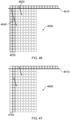
- Figure 23 schematically illustrates a single row/column 2410 of reference samples. If this was the only option available to the intra predictor, the operation would correspond to a previously proposed intra predictor, but the use of a single row/column 2410 could be provided in an intra predictor forming an embodiment of the present disclosure in the context of its optional selection (by the intra mode selector) in combination with the optional selection (by the intra mode selector) of one or more other techniques shown in Figures 24 to 26 .
- Figure 24 shows a pair of rows/columns 2500, 2510 in which, as discussed above, the row/column 2510 is extended by one or more samples 2520, 2530 so as to allow for the use of the full range of prediction directions discussed above.
- Figure 25 schematically represents three rows/columns of reference samples 2600, 2610, 2620.
- the row/column 2620 is extended by one or more samples 2630, 2640 with respect to the second row/column 2610, for the same reasons.
- Figure 23 schematically illustrates four rows/columns of reference samples, mainly rows/columns 2700, 2710, 2720, 2730.
- the row/column 2730 is extended by one or more reference samples 2740, 2750 with respect to the third row/column 2720, for the same reasons as those discussed above.
- Figures 27-30 show, for the example cases of Figures 23-26 respectively, a projected version of the multiple rows/columns of reference samples (shown as shaded blocks in Figures 27-30 ). Note that in at least some examples, the projection process can be dependent upon the prediction direction in use, so a single example for an arbitrary prediction direction is employed in Figures 27-30 . With respect to the projected reference sample, a similar technique employed to that in Figure 17 can be used to derive reference positions and reference samples to apply the technique of Figure 19 .
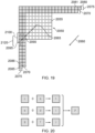
- Figure 31 schematically represents at least part of an operation of an intra mode selector such as the intra mode selector 520 of Figure 8 described above.
- the intra mode selector can operate to detect an appropriate mode for use in intra prediction of a current block or region with respect to a set of reference samples 3205.
- Various techniques have been proposed for achieving this, such as (at least partial) trial encoding and/or analysis of properties of the reference samples, to select the prediction operation amongst the candidate prediction operations.
- any of these techniques can be used, with (in some example arrangements) the techniques being repeated, or applied in multiple instances, in respect of multiple permutations of the number of rows/columns of reference samples.
- permutation is used to indicate a group of rows/columns of reference samples.
- the group might include a row/column spatially nearest to the current block or region, and zero or more next-adjacent rows/columns each progressively spatially further away from the current block or region.
- the intra-mode selector can, in example embodiments, be configured to select, from a set of candidate prediction operations each defining at least a prediction direction, a prediction operation for prediction of samples of a current region of a current image, the current region comprising an array of two or more rows and two or more columns of samples.
- the intra-image predictor is configured to derive predicted samples of the current region with respect to one or more of a group of reference samples of the same image in dependence upon a prediction direction, defined by the selected prediction operation, between a current sample to be predicted and a reference position amongst the reference samples.
- the group of reference samples comprises two or more parallel linear arrays (such as rows, columns, rows and columns (noting that a row and column are still a linear array even with a "corner"), and/or projected arrays) of reference samples disposed at different respective separations from the current region.
- the intra mode selector comprises a mode properties detector 3200 which acts to detect the encoding properties of each mode under test (and, in at least some examples, of each mode with each permutation Pn of numbers n of rows/columns of reference samples available with that mode, where n ranges from 1 to a maximum limit of at least two).
- a coding efficiency detector 3210 detects the coding efficiency for each mode/permutation tested by the mode properties detector 3200.
- the coding efficiency can relate to aspects such as the amount of data needed to encode the residual image which would arise where that mode and permutation of rows/columns to be used, along with the amount of data needed to signal the use of that mode/permutation.
- example arrangements test all 34 directional modes with a simple SAD (sum of absolute differences) test to derive a shortlist of modes most likely to be useful for the current block. The shortlist of modes is then tested with a full encode to select a prediction mode for use.
- SAD sum of absolute differences
- example arrangements may be arranged to use the multi row/column prediction only for testing the shortlist of modes.
- this provides an example in which the intra mode selector is configured to select amongst two or more groups of reference samples, each group comprising a respective different number of parallel arrays of reference samples.
- Figures 32 and 33 are respective schematic flow charts representing possible methods of operation of the intra mode selector of Figure 31 .
- steps 3300...3310 carried out in as many instances (whether in series, as schematically illustrated here, or in parallel) as there are available permutations P of rows/columns of reference samples, relate to the mode properties detector 3200 and coding efficiency detector 3210 detecting a best mode using each possible permutation of rows/columns of reference samples. So, a best mode may be selected using a single row/column of reference samples, another best mode may be selected using two rows/columns of reference samples and so on.
- the prediction may be a weighted sum but this might be for example a 0:100:0:0 weighting rather than necessarily a 25:25:25:25 weighting (where the four weightings are in order of array separation from the current image region, for example, the first, second, third and fourth adjacent rows/columns).
- This could be implemented as a multiplexer.
- the detector 4500 is configured to detect, separately for reference sample positions disposed vertically or horizontally with respect to the current image region, whether samples corresponding to any of the two or more parallel linear arrays of reference samples are unavailable for use in prediction of samples of the current region (being, for example, all candidate prediction modes except those which rely on line stores or sample provision which are not present in respect of the current region) and, if any of the two or more parallel linear arrays of reference samples are unavailable for reference sample positions disposed vertically or horizontally with respect to the current image region, to inhibit selection, by the selector, of a candidate prediction operation dependent upon the unavailable reference samples.
- the detection can take place region by region, since the presence or absence of line stores is generally relevant only to the top row of regions and/or to modes which rely on samples above the current region.
- samples above a current region may not be available simply because the current region is at the very top of the image.
- predetermined value for example grey
- the detector 4500 can detect this situation from the location information 4520 and control the detector 4500 so as to disallow use of modes other than those which rely on the predetermined reference samples.
- the group of reference samples comprises one or more predetermined values; and the detector 4500 is further configured to detect for a current region of a current image if none of the two or more parallel linear arrays is available for use in prediction of samples of the current region and to allow selection as a prediction operation, by the selector, of a candidate prediction operation for that current region dependent upon the predetermined values as reference samples.
- Figure 50 is a schematic flowchart illustrating an image encoding method comprising:
- Figure 51 is a schematic flowchart illustrating an image decoding method comprising:
Landscapes
- Engineering & Computer Science (AREA)
- Multimedia (AREA)
- Signal Processing (AREA)
- Physics & Mathematics (AREA)
- Discrete Mathematics (AREA)
- General Physics & Mathematics (AREA)
- Computing Systems (AREA)
- Theoretical Computer Science (AREA)
- Compression Or Coding Systems Of Tv Signals (AREA)
Applications Claiming Priority (3)
| Application Number | Priority Date | Filing Date | Title |
|---|---|---|---|
| GB1717684.3A GB2567861A (en) | 2017-10-27 | 2017-10-27 | Image data encoding and decoding |
| GB1809024.1A GB2567913A (en) | 2017-10-27 | 2018-06-01 | Image data encoding and decoding |
| PCT/GB2018/053077 WO2019081927A1 (en) | 2017-10-27 | 2018-10-24 | CODING AND DECODING IMAGE DATA |
Publications (2)
| Publication Number | Publication Date |
|---|---|
| EP3701723A1 EP3701723A1 (en) | 2020-09-02 |
| EP3701723B1 true EP3701723B1 (en) | 2025-07-09 |
Family
ID=60580162
Family Applications (1)
| Application Number | Title | Priority Date | Filing Date |
|---|---|---|---|
| EP18797036.3A Active EP3701723B1 (en) | 2017-10-27 | 2018-10-24 | Image data encoding and decoding |
Country Status (13)
| Country | Link |
|---|---|
| US (7) | US10728556B2 (enExample) |
| EP (1) | EP3701723B1 (enExample) |
| JP (2) | JP2021500818A (enExample) |
| CN (1) | CN111279704B (enExample) |
| AU (1) | AU2018357062B2 (enExample) |
| BR (1) | BR112020007835A2 (enExample) |
| CA (1) | CA3080084A1 (enExample) |
| ES (1) | ES3040535T3 (enExample) |
| GB (3) | GB2567861A (enExample) |
| HU (1) | HUE073403T2 (enExample) |
| MX (1) | MX2020003873A (enExample) |
| RU (1) | RU2020113977A (enExample) |
| WO (2) | WO2019081929A1 (enExample) |
Families Citing this family (6)
| Publication number | Priority date | Publication date | Assignee | Title |
|---|---|---|---|---|
| AU2019286133B2 (en) * | 2018-06-15 | 2023-02-16 | Huawei Technologies Co., Ltd. | Method and apparatus for intra prediction |
| CN118945329A (zh) | 2018-06-27 | 2024-11-12 | 株式会社Kt | 对图像进行解码和编码的方法以及用于发送比特流的装置 |
| GB2577336A (en) | 2018-09-24 | 2020-03-25 | Sony Corp | Image data encoding and decoding |
| US11509919B2 (en) * | 2018-10-17 | 2022-11-22 | Tencent America | Reference sample memory size restrictions for intra block copy |
| CN113068025B (zh) | 2018-12-25 | 2023-05-12 | Oppo广东移动通信有限公司 | 解码预测方法、装置及计算机存储介质 |
| EP4222708A1 (en) * | 2020-09-30 | 2023-08-09 | InterDigital CE Patent Holdings, SAS | A method and an apparatus for encoding/decoding at least one attribute of an animated 3d object |
Family Cites Families (29)
| Publication number | Priority date | Publication date | Assignee | Title |
|---|---|---|---|---|
| US20030202590A1 (en) * | 2002-04-30 | 2003-10-30 | Qunshan Gu | Video encoding using direct mode predicted frames |
| US7440500B2 (en) * | 2003-07-15 | 2008-10-21 | Lsi Logic Corporation | Supporting motion vectors outside picture boundaries in motion estimation process |
| JP5686499B2 (ja) * | 2009-01-22 | 2015-03-18 | 株式会社Nttドコモ | 画像予測符号化装置、方法及びプログラム、画像予測復号装置、方法及びプログラム、並びに、符号化・復号システム及び方法 |
| JP2012191295A (ja) * | 2011-03-09 | 2012-10-04 | Canon Inc | 画像符号化装置、画像符号化方法及びプログラム、画像復号装置、画像復号方法及びプログラム |
| US20120236936A1 (en) * | 2011-03-14 | 2012-09-20 | Segall Christopher A | Video coding based on edge determination |
| KR101383775B1 (ko) | 2011-05-20 | 2014-04-14 | 주식회사 케이티 | 화면 내 예측 방법 및 장치 |
| US9077578B1 (en) * | 2011-06-06 | 2015-07-07 | Vuemix, Inc. | Scalable real-time video compositing systems and methods |
| KR20130049525A (ko) | 2011-11-04 | 2013-05-14 | 오수미 | 잔차 블록 복원을 위한 역변환 방법 |
| US9237344B2 (en) | 2012-03-22 | 2016-01-12 | Qualcomm Incorporated | Deriving context for last position coding for video coding |
| US9247251B1 (en) * | 2013-07-26 | 2016-01-26 | Google Inc. | Right-edge extension for quad-tree intra-prediction |
| GB2521828A (en) * | 2013-12-23 | 2015-07-08 | Sony Corp | Data encoding and decoding |
| EP3198867A4 (en) | 2014-10-31 | 2018-04-04 | MediaTek Inc. | Method of improved directional intra prediction for video coding |
| US10659805B2 (en) * | 2015-01-29 | 2020-05-19 | Ecole De Technologie Superieure | Method and apparatus for video intermodal transcoding |
| CN115002455B (zh) * | 2015-06-05 | 2025-03-25 | 杜比实验室特许公司 | 图像编码和解码方法和图像解码设备 |
| PH12018500454B1 (en) * | 2015-09-03 | 2024-02-28 | Mediatek Inc | Method and apparatus of nueral network based processing in video coding |
| EP3148190A1 (en) * | 2015-09-25 | 2017-03-29 | Thomson Licensing | Method and apparatus for intra prediction in video encoding and decoding |
| EP3361726A4 (en) * | 2015-11-24 | 2018-08-15 | Samsung Electronics Co., Ltd. | Method and device for video decoding and method and device for video encoding |
| WO2017105141A1 (ko) * | 2015-12-17 | 2017-06-22 | 삼성전자 주식회사 | 영상을 부호화/복호화 하는 방법 및 그 장치 |
| US10390021B2 (en) * | 2016-03-18 | 2019-08-20 | Mediatek Inc. | Method and apparatus of video coding |
| CN108886617B (zh) | 2016-04-06 | 2021-08-27 | 株式会社Kt | 用于处理视频信号的方法和设备 |
| CN116962721A (zh) * | 2016-05-04 | 2023-10-27 | 微软技术许可有限责任公司 | 利用样本值的非相邻参考线进行帧内图片预测的方法 |
| CA3025488A1 (en) * | 2016-05-25 | 2017-11-30 | Arris Enterprises Llc | Weighted angular prediction for intra coding |
| US10230961B2 (en) * | 2016-06-03 | 2019-03-12 | Mediatek Inc. | Method and apparatus for template-based intra prediction in image and video coding |
| EP4246969B1 (en) * | 2016-06-24 | 2026-04-15 | KT Corporation | Method and apparatus for processing video signal |
| WO2018026166A1 (ko) * | 2016-08-01 | 2018-02-08 | 한국전자통신연구원 | 영상 부호화/복호화 방법, 장치 및 비트스트림을 저장한 기록 매체 |
| CN118694925A (zh) * | 2016-10-04 | 2024-09-24 | Lx 半导体科技有限公司 | 编码/解码设备和发送图像数据的设备 |
| US10951912B2 (en) | 2016-10-05 | 2021-03-16 | Qualcomm Incorporated | Systems and methods for adaptive selection of weights for video coding |
| CN117354501A (zh) * | 2017-07-06 | 2024-01-05 | Lx 半导体科技有限公司 | 图像编码/解码方法、发送方法和数字存储介质 |
| CN118413654A (zh) * | 2017-11-28 | 2024-07-30 | Lx 半导体科技有限公司 | 图像编码/解码设备、传输图像数据的设备和存储介质 |
-
2017
- 2017-10-27 GB GB1717684.3A patent/GB2567861A/en not_active Withdrawn
-
2018
- 2018-06-01 GB GB1809024.1A patent/GB2567913A/en not_active Withdrawn
- 2018-08-01 GB GB1812556.7A patent/GB2567918A/en not_active Withdrawn
- 2018-08-09 US US16/059,685 patent/US10728556B2/en active Active
- 2018-10-24 US US16/756,211 patent/US11330275B2/en active Active
- 2018-10-24 CN CN201880069711.0A patent/CN111279704B/zh active Active
- 2018-10-24 WO PCT/GB2018/053079 patent/WO2019081929A1/en not_active Ceased
- 2018-10-24 HU HUE18797036A patent/HUE073403T2/hu unknown
- 2018-10-24 AU AU2018357062A patent/AU2018357062B2/en active Active
- 2018-10-24 MX MX2020003873A patent/MX2020003873A/es unknown
- 2018-10-24 WO PCT/GB2018/053077 patent/WO2019081927A1/en not_active Ceased
- 2018-10-24 RU RU2020113977A patent/RU2020113977A/ru unknown
- 2018-10-24 ES ES18797036T patent/ES3040535T3/es active Active
- 2018-10-24 CA CA3080084A patent/CA3080084A1/en active Pending
- 2018-10-24 JP JP2020523332A patent/JP2021500818A/ja active Pending
- 2018-10-24 US US16/753,139 patent/US11159803B2/en active Active
- 2018-10-24 BR BR112020007835-2A patent/BR112020007835A2/pt unknown
- 2018-10-24 EP EP18797036.3A patent/EP3701723B1/en active Active
-
2020
- 2020-07-09 US US16/924,900 patent/US11523121B2/en active Active
-
2021
- 2021-07-30 US US17/390,283 patent/US11949882B2/en active Active
-
2022
- 2022-11-21 US US17/990,881 patent/US20230083246A1/en not_active Abandoned
-
2023
- 2023-01-27 US US18/160,767 patent/US12137231B2/en active Active
- 2023-09-13 JP JP2023148233A patent/JP2023166555A/ja active Pending
Also Published As
Similar Documents
| Publication | Publication Date | Title |
|---|---|---|
| US12137231B2 (en) | Image data encoding and decoding | |
| US11290709B2 (en) | Image data encoding and decoding | |
| US10863176B2 (en) | Intra encoding and decoding with variable intra prediction direction sets | |
| GB2564150A (en) | Image data encoding and decoding | |
| EP3701717B1 (en) | Image data encoding and decoding | |
| GB2577337A (en) | Image data encoding and decoding | |
| WO2019081925A1 (en) | CODING AND DECODING IMAGE DATA | |
| WO2019081930A1 (en) | CODING AND DECODING IMAGE DATA | |
| US20200413039A1 (en) | Image data encoding and decoding apparatus and method | |
| WO2019081928A1 (en) | CODING AND DECODING IMAGE DATA | |
| GB2585039A (en) | Image data encoding and decoding |
Legal Events
| Date | Code | Title | Description |
|---|---|---|---|
| STAA | Information on the status of an ep patent application or granted ep patent |
Free format text: STATUS: UNKNOWN |
|
| STAA | Information on the status of an ep patent application or granted ep patent |
Free format text: STATUS: THE INTERNATIONAL PUBLICATION HAS BEEN MADE |
|
| PUAI | Public reference made under article 153(3) epc to a published international application that has entered the european phase |
Free format text: ORIGINAL CODE: 0009012 |
|
| STAA | Information on the status of an ep patent application or granted ep patent |
Free format text: STATUS: REQUEST FOR EXAMINATION WAS MADE |
|
| 17P | Request for examination filed |
Effective date: 20200427 |
|
| AK | Designated contracting states |
Kind code of ref document: A1 Designated state(s): AL AT BE BG CH CY CZ DE DK EE ES FI FR GB GR HR HU IE IS IT LI LT LU LV MC MK MT NL NO PL PT RO RS SE SI SK SM TR |
|
| AX | Request for extension of the european patent |
Extension state: BA ME |
|
| DAV | Request for validation of the european patent (deleted) | ||
| DAX | Request for extension of the european patent (deleted) | ||
| RAP3 | Party data changed (applicant data changed or rights of an application transferred) |
Owner name: SONY GROUP CORPORATION Owner name: SONY EUROPE LIMITED |
|
| STAA | Information on the status of an ep patent application or granted ep patent |
Free format text: STATUS: EXAMINATION IS IN PROGRESS |
|
| 17Q | First examination report despatched |
Effective date: 20230118 |
|
| GRAP | Despatch of communication of intention to grant a patent |
Free format text: ORIGINAL CODE: EPIDOSNIGR1 |
|
| STAA | Information on the status of an ep patent application or granted ep patent |
Free format text: STATUS: GRANT OF PATENT IS INTENDED |
|
| RIC1 | Information provided on ipc code assigned before grant |
Ipc: H04N 19/156 20140101ALN20250203BHEP Ipc: H04N 19/167 20140101ALI20250203BHEP Ipc: H04N 19/159 20140101ALI20250203BHEP Ipc: H04N 19/11 20140101ALI20250203BHEP Ipc: H04N 19/176 20140101ALI20250203BHEP Ipc: H04N 19/593 20140101AFI20250203BHEP |
|
| INTG | Intention to grant announced |
Effective date: 20250213 |
|
| GRAS | Grant fee paid |
Free format text: ORIGINAL CODE: EPIDOSNIGR3 |
|
| GRAA | (expected) grant |
Free format text: ORIGINAL CODE: 0009210 |
|
| STAA | Information on the status of an ep patent application or granted ep patent |
Free format text: STATUS: THE PATENT HAS BEEN GRANTED |
|
| P01 | Opt-out of the competence of the unified patent court (upc) registered |
Free format text: CASE NUMBER: APP_24072/2025 Effective date: 20250520 |
|
| AK | Designated contracting states |
Kind code of ref document: B1 Designated state(s): AL AT BE BG CH CY CZ DE DK EE ES FI FR GB GR HR HU IE IS IT LI LT LU LV MC MK MT NL NO PL PT RO RS SE SI SK SM TR |
|
| REG | Reference to a national code |
Ref country code: GB Ref legal event code: FG4D |
|
| REG | Reference to a national code |
Ref country code: CH Ref legal event code: EP |
|
| REG | Reference to a national code |
Ref country code: IE Ref legal event code: FG4D |
|
| REG | Reference to a national code |
Ref country code: DE Ref legal event code: R096 Ref document number: 602018083439 Country of ref document: DE |
|
| REG | Reference to a national code |
Ref country code: NL Ref legal event code: FP |
|
| PGFP | Annual fee paid to national office [announced via postgrant information from national office to epo] |
Ref country code: NL Payment date: 20250923 Year of fee payment: 8 |
|
| PGFP | Annual fee paid to national office [announced via postgrant information from national office to epo] |
Ref country code: GB Payment date: 20250923 Year of fee payment: 8 |
|
| PGFP | Annual fee paid to national office [announced via postgrant information from national office to epo] |
Ref country code: FR Payment date: 20250925 Year of fee payment: 8 |
|
| REG | Reference to a national code |
Ref country code: ES Ref legal event code: FG2A Ref document number: 3040535 Country of ref document: ES Kind code of ref document: T3 Effective date: 20251103 |
|
| PGFP | Annual fee paid to national office [announced via postgrant information from national office to epo] |
Ref country code: HU Payment date: 20251029 Year of fee payment: 8 |
|
| PG25 | Lapsed in a contracting state [announced via postgrant information from national office to epo] |
Ref country code: PT Free format text: LAPSE BECAUSE OF FAILURE TO SUBMIT A TRANSLATION OF THE DESCRIPTION OR TO PAY THE FEE WITHIN THE PRESCRIBED TIME-LIMIT Effective date: 20251110 |
|
| REG | Reference to a national code |
Ref country code: AT Ref legal event code: MK05 Ref document number: 1812972 Country of ref document: AT Kind code of ref document: T Effective date: 20250709 |
|
| PG25 | Lapsed in a contracting state [announced via postgrant information from national office to epo] |
Ref country code: IS Free format text: LAPSE BECAUSE OF FAILURE TO SUBMIT A TRANSLATION OF THE DESCRIPTION OR TO PAY THE FEE WITHIN THE PRESCRIBED TIME-LIMIT Effective date: 20251109 |
|
| PGFP | Annual fee paid to national office [announced via postgrant information from national office to epo] |
Ref country code: DE Payment date: 20250923 Year of fee payment: 8 |
|
| PG25 | Lapsed in a contracting state [announced via postgrant information from national office to epo] |
Ref country code: NO Free format text: LAPSE BECAUSE OF FAILURE TO SUBMIT A TRANSLATION OF THE DESCRIPTION OR TO PAY THE FEE WITHIN THE PRESCRIBED TIME-LIMIT Effective date: 20251009 |
|
| REG | Reference to a national code |
Ref country code: LT Ref legal event code: MG9D |
|
| PG25 | Lapsed in a contracting state [announced via postgrant information from national office to epo] |
Ref country code: AT Free format text: LAPSE BECAUSE OF FAILURE TO SUBMIT A TRANSLATION OF THE DESCRIPTION OR TO PAY THE FEE WITHIN THE PRESCRIBED TIME-LIMIT Effective date: 20250709 |
|
| PG25 | Lapsed in a contracting state [announced via postgrant information from national office to epo] |
Ref country code: FI Free format text: LAPSE BECAUSE OF FAILURE TO SUBMIT A TRANSLATION OF THE DESCRIPTION OR TO PAY THE FEE WITHIN THE PRESCRIBED TIME-LIMIT Effective date: 20250709 |
|
| PG25 | Lapsed in a contracting state [announced via postgrant information from national office to epo] |
Ref country code: HR Free format text: LAPSE BECAUSE OF FAILURE TO SUBMIT A TRANSLATION OF THE DESCRIPTION OR TO PAY THE FEE WITHIN THE PRESCRIBED TIME-LIMIT Effective date: 20250709 |
|
| PG25 | Lapsed in a contracting state [announced via postgrant information from national office to epo] |
Ref country code: GR Free format text: LAPSE BECAUSE OF FAILURE TO SUBMIT A TRANSLATION OF THE DESCRIPTION OR TO PAY THE FEE WITHIN THE PRESCRIBED TIME-LIMIT Effective date: 20251010 |
|
| PG25 | Lapsed in a contracting state [announced via postgrant information from national office to epo] |
Ref country code: SE Free format text: LAPSE BECAUSE OF FAILURE TO SUBMIT A TRANSLATION OF THE DESCRIPTION OR TO PAY THE FEE WITHIN THE PRESCRIBED TIME-LIMIT Effective date: 20250709 |
|
| PG25 | Lapsed in a contracting state [announced via postgrant information from national office to epo] |
Ref country code: LV Free format text: LAPSE BECAUSE OF FAILURE TO SUBMIT A TRANSLATION OF THE DESCRIPTION OR TO PAY THE FEE WITHIN THE PRESCRIBED TIME-LIMIT Effective date: 20250709 |
|
| PG25 | Lapsed in a contracting state [announced via postgrant information from national office to epo] |
Ref country code: BG Free format text: LAPSE BECAUSE OF FAILURE TO SUBMIT A TRANSLATION OF THE DESCRIPTION OR TO PAY THE FEE WITHIN THE PRESCRIBED TIME-LIMIT Effective date: 20250709 Ref country code: PL Free format text: LAPSE BECAUSE OF FAILURE TO SUBMIT A TRANSLATION OF THE DESCRIPTION OR TO PAY THE FEE WITHIN THE PRESCRIBED TIME-LIMIT Effective date: 20250709 |
|
| PG25 | Lapsed in a contracting state [announced via postgrant information from national office to epo] |
Ref country code: RS Free format text: LAPSE BECAUSE OF FAILURE TO SUBMIT A TRANSLATION OF THE DESCRIPTION OR TO PAY THE FEE WITHIN THE PRESCRIBED TIME-LIMIT Effective date: 20251009 |
|
| REG | Reference to a national code |
Ref country code: HU Ref legal event code: AG4A Ref document number: E073403 Country of ref document: HU |
|
| PGFP | Annual fee paid to national office [announced via postgrant information from national office to epo] |
Ref country code: ES Payment date: 20251103 Year of fee payment: 8 |
|
| PG25 | Lapsed in a contracting state [announced via postgrant information from national office to epo] |
Ref country code: RO Free format text: LAPSE BECAUSE OF FAILURE TO SUBMIT A TRANSLATION OF THE DESCRIPTION OR TO PAY THE FEE WITHIN THE PRESCRIBED TIME-LIMIT Effective date: 20250709 |
|
| PG25 | Lapsed in a contracting state [announced via postgrant information from national office to epo] |
Ref country code: SM Free format text: LAPSE BECAUSE OF FAILURE TO SUBMIT A TRANSLATION OF THE DESCRIPTION OR TO PAY THE FEE WITHIN THE PRESCRIBED TIME-LIMIT Effective date: 20250709 |
|
| PG25 | Lapsed in a contracting state [announced via postgrant information from national office to epo] |
Ref country code: DK Free format text: LAPSE BECAUSE OF FAILURE TO SUBMIT A TRANSLATION OF THE DESCRIPTION OR TO PAY THE FEE WITHIN THE PRESCRIBED TIME-LIMIT Effective date: 20250709 |
|
| PG25 | Lapsed in a contracting state [announced via postgrant information from national office to epo] |
Ref country code: IT Free format text: LAPSE BECAUSE OF FAILURE TO SUBMIT A TRANSLATION OF THE DESCRIPTION OR TO PAY THE FEE WITHIN THE PRESCRIBED TIME-LIMIT Effective date: 20250709 |
|
| PG25 | Lapsed in a contracting state [announced via postgrant information from national office to epo] |
Ref country code: CZ Free format text: LAPSE BECAUSE OF FAILURE TO SUBMIT A TRANSLATION OF THE DESCRIPTION OR TO PAY THE FEE WITHIN THE PRESCRIBED TIME-LIMIT Effective date: 20250709 |
|
| PG25 | Lapsed in a contracting state [announced via postgrant information from national office to epo] |
Ref country code: SK Free format text: LAPSE BECAUSE OF FAILURE TO SUBMIT A TRANSLATION OF THE DESCRIPTION OR TO PAY THE FEE WITHIN THE PRESCRIBED TIME-LIMIT Effective date: 20250709 Ref country code: EE Free format text: LAPSE BECAUSE OF FAILURE TO SUBMIT A TRANSLATION OF THE DESCRIPTION OR TO PAY THE FEE WITHIN THE PRESCRIBED TIME-LIMIT Effective date: 20250709 |