EP3701286B1 - A method and system for combining sensor data - Google Patents
A method and system for combining sensor data Download PDFInfo
- Publication number
- EP3701286B1 EP3701286B1 EP18797058.7A EP18797058A EP3701286B1 EP 3701286 B1 EP3701286 B1 EP 3701286B1 EP 18797058 A EP18797058 A EP 18797058A EP 3701286 B1 EP3701286 B1 EP 3701286B1
- Authority
- EP
- European Patent Office
- Prior art keywords
- data
- sensor
- time
- motion
- interest
- Prior art date
- Legal status (The legal status is an assumption and is not a legal conclusion. Google has not performed a legal analysis and makes no representation as to the accuracy of the status listed.)
- Active
Links
- 238000000034 method Methods 0.000 title claims description 46
- 230000033001 locomotion Effects 0.000 claims description 159
- 238000004458 analytical method Methods 0.000 claims description 61
- 238000005259 measurement Methods 0.000 claims description 40
- 230000004044 response Effects 0.000 claims description 3
- 230000006870 function Effects 0.000 description 13
- 238000012545 processing Methods 0.000 description 12
- 230000001133 acceleration Effects 0.000 description 10
- 230000008901 benefit Effects 0.000 description 10
- 230000009183 running Effects 0.000 description 10
- 230000009184 walking Effects 0.000 description 9
- 230000008859 change Effects 0.000 description 8
- 238000010586 diagram Methods 0.000 description 7
- 230000010354 integration Effects 0.000 description 7
- 238000004891 communication Methods 0.000 description 6
- 238000005070 sampling Methods 0.000 description 4
- 238000010923 batch production Methods 0.000 description 3
- 238000012937 correction Methods 0.000 description 3
- 230000001965 increasing effect Effects 0.000 description 3
- 230000009286 beneficial effect Effects 0.000 description 2
- 230000001413 cellular effect Effects 0.000 description 2
- 230000009193 crawling Effects 0.000 description 2
- 238000011156 evaluation Methods 0.000 description 2
- 230000006872 improvement Effects 0.000 description 2
- 230000003993 interaction Effects 0.000 description 2
- 230000008569 process Effects 0.000 description 2
- 238000012935 Averaging Methods 0.000 description 1
- 238000013459 approach Methods 0.000 description 1
- 230000001174 ascending effect Effects 0.000 description 1
- 238000009530 blood pressure measurement Methods 0.000 description 1
- 238000004364 calculation method Methods 0.000 description 1
- 238000010276 construction Methods 0.000 description 1
- 238000007796 conventional method Methods 0.000 description 1
- 230000001351 cycling effect Effects 0.000 description 1
- 230000001419 dependent effect Effects 0.000 description 1
- 238000001514 detection method Methods 0.000 description 1
- 230000000694 effects Effects 0.000 description 1
- 230000002708 enhancing effect Effects 0.000 description 1
- 238000001914 filtration Methods 0.000 description 1
- 230000005021 gait Effects 0.000 description 1
- 230000005358 geomagnetic field Effects 0.000 description 1
- 230000005484 gravity Effects 0.000 description 1
- 238000009499 grossing Methods 0.000 description 1
- 238000010801 machine learning Methods 0.000 description 1
- 238000012986 modification Methods 0.000 description 1
- 230000004048 modification Effects 0.000 description 1
- 230000009467 reduction Effects 0.000 description 1
- 238000005096 rolling process Methods 0.000 description 1
- 230000003068 static effect Effects 0.000 description 1
- 238000012360 testing method Methods 0.000 description 1
Images


Classifications
-
- G—PHYSICS
- G01—MEASURING; TESTING
- G01S—RADIO DIRECTION-FINDING; RADIO NAVIGATION; DETERMINING DISTANCE OR VELOCITY BY USE OF RADIO WAVES; LOCATING OR PRESENCE-DETECTING BY USE OF THE REFLECTION OR RERADIATION OF RADIO WAVES; ANALOGOUS ARRANGEMENTS USING OTHER WAVES
- G01S19/00—Satellite radio beacon positioning systems; Determining position, velocity or attitude using signals transmitted by such systems
- G01S19/38—Determining a navigation solution using signals transmitted by a satellite radio beacon positioning system
- G01S19/39—Determining a navigation solution using signals transmitted by a satellite radio beacon positioning system the satellite radio beacon positioning system transmitting time-stamped messages, e.g. GPS [Global Positioning System], GLONASS [Global Orbiting Navigation Satellite System] or GALILEO
- G01S19/42—Determining position
- G01S19/48—Determining position by combining or switching between position solutions derived from the satellite radio beacon positioning system and position solutions derived from a further system
-
- G—PHYSICS
- G01—MEASURING; TESTING
- G01C—MEASURING DISTANCES, LEVELS OR BEARINGS; SURVEYING; NAVIGATION; GYROSCOPIC INSTRUMENTS; PHOTOGRAMMETRY OR VIDEOGRAMMETRY
- G01C21/00—Navigation; Navigational instruments not provided for in groups G01C1/00 - G01C19/00
- G01C21/005—Navigation; Navigational instruments not provided for in groups G01C1/00 - G01C19/00 with correlation of navigation data from several sources, e.g. map or contour matching
-
- G—PHYSICS
- G01—MEASURING; TESTING
- G01C—MEASURING DISTANCES, LEVELS OR BEARINGS; SURVEYING; NAVIGATION; GYROSCOPIC INSTRUMENTS; PHOTOGRAMMETRY OR VIDEOGRAMMETRY
- G01C21/00—Navigation; Navigational instruments not provided for in groups G01C1/00 - G01C19/00
- G01C21/10—Navigation; Navigational instruments not provided for in groups G01C1/00 - G01C19/00 by using measurements of speed or acceleration
- G01C21/12—Navigation; Navigational instruments not provided for in groups G01C1/00 - G01C19/00 by using measurements of speed or acceleration executed aboard the object being navigated; Dead reckoning
- G01C21/16—Navigation; Navigational instruments not provided for in groups G01C1/00 - G01C19/00 by using measurements of speed or acceleration executed aboard the object being navigated; Dead reckoning by integrating acceleration or speed, i.e. inertial navigation
- G01C21/165—Navigation; Navigational instruments not provided for in groups G01C1/00 - G01C19/00 by using measurements of speed or acceleration executed aboard the object being navigated; Dead reckoning by integrating acceleration or speed, i.e. inertial navigation combined with non-inertial navigation instruments
- G01C21/1652—Navigation; Navigational instruments not provided for in groups G01C1/00 - G01C19/00 by using measurements of speed or acceleration executed aboard the object being navigated; Dead reckoning by integrating acceleration or speed, i.e. inertial navigation combined with non-inertial navigation instruments with ranging devices, e.g. LIDAR or RADAR
-
- G—PHYSICS
- G01—MEASURING; TESTING
- G01C—MEASURING DISTANCES, LEVELS OR BEARINGS; SURVEYING; NAVIGATION; GYROSCOPIC INSTRUMENTS; PHOTOGRAMMETRY OR VIDEOGRAMMETRY
- G01C21/00—Navigation; Navigational instruments not provided for in groups G01C1/00 - G01C19/00
- G01C21/10—Navigation; Navigational instruments not provided for in groups G01C1/00 - G01C19/00 by using measurements of speed or acceleration
- G01C21/12—Navigation; Navigational instruments not provided for in groups G01C1/00 - G01C19/00 by using measurements of speed or acceleration executed aboard the object being navigated; Dead reckoning
- G01C21/16—Navigation; Navigational instruments not provided for in groups G01C1/00 - G01C19/00 by using measurements of speed or acceleration executed aboard the object being navigated; Dead reckoning by integrating acceleration or speed, i.e. inertial navigation
- G01C21/165—Navigation; Navigational instruments not provided for in groups G01C1/00 - G01C19/00 by using measurements of speed or acceleration executed aboard the object being navigated; Dead reckoning by integrating acceleration or speed, i.e. inertial navigation combined with non-inertial navigation instruments
- G01C21/1654—Navigation; Navigational instruments not provided for in groups G01C1/00 - G01C19/00 by using measurements of speed or acceleration executed aboard the object being navigated; Dead reckoning by integrating acceleration or speed, i.e. inertial navigation combined with non-inertial navigation instruments with electromagnetic compass
-
- G—PHYSICS
- G01—MEASURING; TESTING
- G01C—MEASURING DISTANCES, LEVELS OR BEARINGS; SURVEYING; NAVIGATION; GYROSCOPIC INSTRUMENTS; PHOTOGRAMMETRY OR VIDEOGRAMMETRY
- G01C21/00—Navigation; Navigational instruments not provided for in groups G01C1/00 - G01C19/00
- G01C21/10—Navigation; Navigational instruments not provided for in groups G01C1/00 - G01C19/00 by using measurements of speed or acceleration
- G01C21/12—Navigation; Navigational instruments not provided for in groups G01C1/00 - G01C19/00 by using measurements of speed or acceleration executed aboard the object being navigated; Dead reckoning
- G01C21/16—Navigation; Navigational instruments not provided for in groups G01C1/00 - G01C19/00 by using measurements of speed or acceleration executed aboard the object being navigated; Dead reckoning by integrating acceleration or speed, i.e. inertial navigation
- G01C21/165—Navigation; Navigational instruments not provided for in groups G01C1/00 - G01C19/00 by using measurements of speed or acceleration executed aboard the object being navigated; Dead reckoning by integrating acceleration or speed, i.e. inertial navigation combined with non-inertial navigation instruments
- G01C21/1656—Navigation; Navigational instruments not provided for in groups G01C1/00 - G01C19/00 by using measurements of speed or acceleration executed aboard the object being navigated; Dead reckoning by integrating acceleration or speed, i.e. inertial navigation combined with non-inertial navigation instruments with passive imaging devices, e.g. cameras
-
- G—PHYSICS
- G01—MEASURING; TESTING
- G01C—MEASURING DISTANCES, LEVELS OR BEARINGS; SURVEYING; NAVIGATION; GYROSCOPIC INSTRUMENTS; PHOTOGRAMMETRY OR VIDEOGRAMMETRY
- G01C21/00—Navigation; Navigational instruments not provided for in groups G01C1/00 - G01C19/00
- G01C21/10—Navigation; Navigational instruments not provided for in groups G01C1/00 - G01C19/00 by using measurements of speed or acceleration
- G01C21/12—Navigation; Navigational instruments not provided for in groups G01C1/00 - G01C19/00 by using measurements of speed or acceleration executed aboard the object being navigated; Dead reckoning
- G01C21/16—Navigation; Navigational instruments not provided for in groups G01C1/00 - G01C19/00 by using measurements of speed or acceleration executed aboard the object being navigated; Dead reckoning by integrating acceleration or speed, i.e. inertial navigation
- G01C21/18—Stabilised platforms, e.g. by gyroscope
-
- G—PHYSICS
- G01—MEASURING; TESTING
- G01C—MEASURING DISTANCES, LEVELS OR BEARINGS; SURVEYING; NAVIGATION; GYROSCOPIC INSTRUMENTS; PHOTOGRAMMETRY OR VIDEOGRAMMETRY
- G01C21/00—Navigation; Navigational instruments not provided for in groups G01C1/00 - G01C19/00
- G01C21/10—Navigation; Navigational instruments not provided for in groups G01C1/00 - G01C19/00 by using measurements of speed or acceleration
- G01C21/12—Navigation; Navigational instruments not provided for in groups G01C1/00 - G01C19/00 by using measurements of speed or acceleration executed aboard the object being navigated; Dead reckoning
- G01C21/16—Navigation; Navigational instruments not provided for in groups G01C1/00 - G01C19/00 by using measurements of speed or acceleration executed aboard the object being navigated; Dead reckoning by integrating acceleration or speed, i.e. inertial navigation
- G01C21/183—Compensation of inertial measurements, e.g. for temperature effects
- G01C21/185—Compensation of inertial measurements, e.g. for temperature effects for gravity
-
- G—PHYSICS
- G01—MEASURING; TESTING
- G01C—MEASURING DISTANCES, LEVELS OR BEARINGS; SURVEYING; NAVIGATION; GYROSCOPIC INSTRUMENTS; PHOTOGRAMMETRY OR VIDEOGRAMMETRY
- G01C21/00—Navigation; Navigational instruments not provided for in groups G01C1/00 - G01C19/00
- G01C21/10—Navigation; Navigational instruments not provided for in groups G01C1/00 - G01C19/00 by using measurements of speed or acceleration
- G01C21/12—Navigation; Navigational instruments not provided for in groups G01C1/00 - G01C19/00 by using measurements of speed or acceleration executed aboard the object being navigated; Dead reckoning
- G01C21/16—Navigation; Navigational instruments not provided for in groups G01C1/00 - G01C19/00 by using measurements of speed or acceleration executed aboard the object being navigated; Dead reckoning by integrating acceleration or speed, i.e. inertial navigation
- G01C21/183—Compensation of inertial measurements, e.g. for temperature effects
- G01C21/188—Compensation of inertial measurements, e.g. for temperature effects for accumulated errors, e.g. by coupling inertial systems with absolute positioning systems
-
- G—PHYSICS
- G01—MEASURING; TESTING
- G01C—MEASURING DISTANCES, LEVELS OR BEARINGS; SURVEYING; NAVIGATION; GYROSCOPIC INSTRUMENTS; PHOTOGRAMMETRY OR VIDEOGRAMMETRY
- G01C21/00—Navigation; Navigational instruments not provided for in groups G01C1/00 - G01C19/00
- G01C21/26—Navigation; Navigational instruments not provided for in groups G01C1/00 - G01C19/00 specially adapted for navigation in a road network
- G01C21/28—Navigation; Navigational instruments not provided for in groups G01C1/00 - G01C19/00 specially adapted for navigation in a road network with correlation of data from several navigational instruments
-
- G—PHYSICS
- G01—MEASURING; TESTING
- G01C—MEASURING DISTANCES, LEVELS OR BEARINGS; SURVEYING; NAVIGATION; GYROSCOPIC INSTRUMENTS; PHOTOGRAMMETRY OR VIDEOGRAMMETRY
- G01C22/00—Measuring distance traversed on the ground by vehicles, persons, animals or other moving solid bodies, e.g. using odometers, using pedometers
- G01C22/006—Pedometers
-
- G—PHYSICS
- G01—MEASURING; TESTING
- G01S—RADIO DIRECTION-FINDING; RADIO NAVIGATION; DETERMINING DISTANCE OR VELOCITY BY USE OF RADIO WAVES; LOCATING OR PRESENCE-DETECTING BY USE OF THE REFLECTION OR RERADIATION OF RADIO WAVES; ANALOGOUS ARRANGEMENTS USING OTHER WAVES
- G01S19/00—Satellite radio beacon positioning systems; Determining position, velocity or attitude using signals transmitted by such systems
- G01S19/38—Determining a navigation solution using signals transmitted by a satellite radio beacon positioning system
- G01S19/39—Determining a navigation solution using signals transmitted by a satellite radio beacon positioning system the satellite radio beacon positioning system transmitting time-stamped messages, e.g. GPS [Global Positioning System], GLONASS [Global Orbiting Navigation Satellite System] or GALILEO
- G01S19/396—Determining accuracy or reliability of position or pseudorange measurements
-
- G—PHYSICS
- G01—MEASURING; TESTING
- G01S—RADIO DIRECTION-FINDING; RADIO NAVIGATION; DETERMINING DISTANCE OR VELOCITY BY USE OF RADIO WAVES; LOCATING OR PRESENCE-DETECTING BY USE OF THE REFLECTION OR RERADIATION OF RADIO WAVES; ANALOGOUS ARRANGEMENTS USING OTHER WAVES
- G01S19/00—Satellite radio beacon positioning systems; Determining position, velocity or attitude using signals transmitted by such systems
- G01S19/38—Determining a navigation solution using signals transmitted by a satellite radio beacon positioning system
- G01S19/39—Determining a navigation solution using signals transmitted by a satellite radio beacon positioning system the satellite radio beacon positioning system transmitting time-stamped messages, e.g. GPS [Global Positioning System], GLONASS [Global Orbiting Navigation Satellite System] or GALILEO
- G01S19/42—Determining position
- G01S19/48—Determining position by combining or switching between position solutions derived from the satellite radio beacon positioning system and position solutions derived from a further system
- G01S19/485—Determining position by combining or switching between position solutions derived from the satellite radio beacon positioning system and position solutions derived from a further system whereby the further system is an optical system or imaging system
-
- G—PHYSICS
- G01—MEASURING; TESTING
- G01S—RADIO DIRECTION-FINDING; RADIO NAVIGATION; DETERMINING DISTANCE OR VELOCITY BY USE OF RADIO WAVES; LOCATING OR PRESENCE-DETECTING BY USE OF THE REFLECTION OR RERADIATION OF RADIO WAVES; ANALOGOUS ARRANGEMENTS USING OTHER WAVES
- G01S19/00—Satellite radio beacon positioning systems; Determining position, velocity or attitude using signals transmitted by such systems
- G01S19/38—Determining a navigation solution using signals transmitted by a satellite radio beacon positioning system
- G01S19/39—Determining a navigation solution using signals transmitted by a satellite radio beacon positioning system the satellite radio beacon positioning system transmitting time-stamped messages, e.g. GPS [Global Positioning System], GLONASS [Global Orbiting Navigation Satellite System] or GALILEO
- G01S19/42—Determining position
- G01S19/48—Determining position by combining or switching between position solutions derived from the satellite radio beacon positioning system and position solutions derived from a further system
- G01S19/49—Determining position by combining or switching between position solutions derived from the satellite radio beacon positioning system and position solutions derived from a further system whereby the further system is an inertial position system, e.g. loosely-coupled
-
- G—PHYSICS
- G01—MEASURING; TESTING
- G01S—RADIO DIRECTION-FINDING; RADIO NAVIGATION; DETERMINING DISTANCE OR VELOCITY BY USE OF RADIO WAVES; LOCATING OR PRESENCE-DETECTING BY USE OF THE REFLECTION OR RERADIATION OF RADIO WAVES; ANALOGOUS ARRANGEMENTS USING OTHER WAVES
- G01S5/00—Position-fixing by co-ordinating two or more direction or position line determinations; Position-fixing by co-ordinating two or more distance determinations
- G01S5/01—Determining conditions which influence positioning, e.g. radio environment, state of motion or energy consumption
- G01S5/017—Detecting state or type of motion
-
- G—PHYSICS
- G01—MEASURING; TESTING
- G01S—RADIO DIRECTION-FINDING; RADIO NAVIGATION; DETERMINING DISTANCE OR VELOCITY BY USE OF RADIO WAVES; LOCATING OR PRESENCE-DETECTING BY USE OF THE REFLECTION OR RERADIATION OF RADIO WAVES; ANALOGOUS ARRANGEMENTS USING OTHER WAVES
- G01S5/00—Position-fixing by co-ordinating two or more direction or position line determinations; Position-fixing by co-ordinating two or more distance determinations
- G01S5/01—Determining conditions which influence positioning, e.g. radio environment, state of motion or energy consumption
- G01S5/018—Involving non-radio wave signals or measurements
-
- A—HUMAN NECESSITIES
- A61—MEDICAL OR VETERINARY SCIENCE; HYGIENE
- A61B—DIAGNOSIS; SURGERY; IDENTIFICATION
- A61B5/00—Measuring for diagnostic purposes; Identification of persons
- A61B5/103—Detecting, measuring or recording devices for testing the shape, pattern, colour, size or movement of the body or parts thereof, for diagnostic purposes
- A61B5/11—Measuring movement of the entire body or parts thereof, e.g. head or hand tremor, mobility of a limb
Definitions
- the present invention is directed to a method and system for combining data obtained by sensors, and has particular application in the field of navigation systems.
- a traditional inertial navigation system uses standard mechanics equations to convert measurements from inertial measurement units (for example accelerometers, gyroscopes etc.) into navigation data, such as velocity, orientation and position.
- inertial measurement units for example accelerometers, gyroscopes etc.
- a known problem with such a system is that of numerical integration error, which manifests as rapidly increasing errors in the derived navigation data.
- the inertial navigation equations typically involve the determination of orientation, velocity and position through numerical integration of successive rotation-rate and acceleration measurements.
- the integration of measurement errors results in an ever increasing velocity error, which in turn is accumulated into an even more rapidly-increasing position error.
- the effects of numerical integration error are particularly pronounced in the case of low-cost inertial measurement units (IMUs), the sensors of which are relatively noisy, possess large alignment and scale-factor errors, and have biases which may drift significantly over time or with changes in temperature.
- IMUs low-cost inertial measurement units
- GNSS Global Navigation Satellite System
- smart devices such as smart phones may be carried in a variety of different positions and orientations with respect to the user, who may frequently change his or her manner of motion.
- a smart phone user may start a journey by walking with the smart phone positioned in a pocket.
- the phone On receipt of a call, the phone may be moved to the user's ear, during which time the user has to run for a bus, after which the user spends the remainder of the journey travelling by bus.
- Such changes in motion of the user and relative position and orientation of the device with respect to the user can introduce further error into the final navigation solution in comparison to, for example, traditional strap-down systems where inertial measurement units are provided in fixed positions and orientations with respect to their host platform.
- EP3211371 discloses methods of enhancing a navigation solution of a device by performing multiple pass smoothing.
- WO2017/033141 discloses techniques for locating a mobile device using captured or determined environment data.
- US2015/185045 discloses techniques for dynamic computation of distance of travel, based on repeatable motion units such as stride length.
- US2008/214360 discloses further methods for estimating motion parameters corresponding to a user.
- the inventors have realised that the problems outlined above in the introduction section can be overcome by the method of the present invention.
- the method provides a significant improvement over state-of-the-art Markovian methods that use statistical noise filters such as Kalman filters to filter data by comparing instantaneous data with the corresponding instantaneous estimates from a model.
- the method of the present invention uses multiple time periods (or time “windows") of various lengths to process multiple sensor data streams, in order to combine (or "fuse") sensor measurements with motion models at a given time epoch with greater confidence and accuracy than is possible with traditional "single epoch” methods.
- the method finds particular benefit when the first and/or second sensors are low-cost sensors (for example as seen in smart phones) which are typically of low quality and have large inherent biases.
- the term "evolution” is used to mean the change in the value of the metric of interest over time.
- the metric of interest could be a position of a device, and thus the evolution of the position of the device over time could be determined, providing an accurate profile of a journey taken by the device.
- the metric of interest could comprise any metric that may be determined from a sensor configured to make measurements from which position or movement may be determined.
- Such metrics include a position, a range, a speed, a velocity, a trajectory, an altitude, an attitude (orientation), a compass heading, a stepping cadence, a step length, a distance travelled, a motion context, a position context, an output power, a calorie count, a sensor bias, a sensor scale factor, and a sensor alignment error.
- Other metrics might be included in this list as would be evident to one skilled in the art.
- the at least one sensor is configured to make measurements from which position or movement can be determined.
- the sensor may measure position or movement directly, for example a GNSS sensor where the measurement value is a position or movement value, or indirectly, for example a light sensor from which the sensor's position may be inferred, for example that it is within an enclosed space such as a bag.
- the first and second data are obtained in first and second time periods, and the evolution of the metric of interest is determined between first and second time instances, wherein at least one of the first and second time instances is within at least one of the first and second time periods.
- a "time period" is the period of time that elapses between two spaced apart time instances, which may or may not be the first and second time instances.
- the first and second time instances may define the first time period.
- the method further comprises analysing the first and second data over at least a part of the respective first and second time period in order to assess the reliability and/or accuracy of the first and second data and to obtain corrected first data and/or corrected second data, wherein the step of analysing the first and second data comprises comparing said data with each other and/or the motion model; and wherein the evolution of the metric of interest is constrained by at least one of the corrected first data, corrected second data and the motion model of the first and/or second platform.
- said corrected first data and/or corrected second data are more accurate and/or reliable than the respective first and/or second data.
- the corrected first and/or second data may be obtained by correcting at least one error in the obtained first and/or second data.
- Such analyses of the first and second data provide further advantages over state-of-the-art methods which do not perform such analyses before processing the obtained data and providing their metric of interest solution.
- the present invention beneficially allows data which are more reliable and/or accurate to be used in the determination of the metric of interest, therefore providing a more accurate and reliable solution to a user.
- the analysing the first and second data may comprise performing self-consistency checks, which may for example comprise analysing the data from a given sensor across its corresponding time period. Typically this may include analysing the data to ensure that it does not violate the accepted laws of Physics.
- the first and/or second data may be obtained from a GNSS sensor and show a positioning trace that is smooth with distances of 1m between positions at 1s update intervals, then suddenly shows a single value 1km away before returning near the original sequence of positions. From this we can infer that the "1 km" data point is not consistent with the remainder of the data, and can therefore be ignored in determining the evolution of the metric of interest.
- the analysis of the first and second data comprises comparing said data with each other and/or the motion model.
- this analysis may comprise determining at least one data point of the first and second data that does not correspond to the motion model, and correcting for said at least one data point.
- the motion model (the motion model will be explained in more detail below) is that for a running user ("running"), and that on an analysis of the first and/or second data, a spurious data point is highlighted that does not correspond to such a motion - for example a data point that would suggest the sensor moved a distance in a time frame that would be inconsistent with someone who was running - such an erroneous data point can be corrected for (e.g. removed) in order to obtain the evolution of the metric of interest with improved accuracy.
- Such an analysis aids in avoiding spurious results that are a common problem in GNSS systems for example.
- data from at least three sensors may be compared with data from first and second sensors obtained in first and second time periods.
- the third time period may wholly or partially overlap with the first and/or second time periods.
- the durations and/or amount of overlap of the first and second time periods with respect to each other are chosen so as to allow for optimal analysing of the first and/or second data.
- the durations of the first and second time periods are determined based on at least one of the sampling frequency of the respective sensor, the required statistical confidence of the obtained data, and the amount of data required to identify any erroneous results. For example, in order to determine whether a platform is static or not, a time period is required in which to obtain the data necessary to make such a determination. A hundred measurements may be required in order to get a clear measure of the standard deviation of the statistics of the obtained data, therefore requiring a time duration of 100/f s , where f s is the sampling frequency of the respective sensor.
- a rolling window of 5-10 data points may only be required. This assumes a relatively smooth motion of the platform of interest.
- a GNSS sensor providing a time-series of measurements of position experiences interference for a short period during which the data are identified as corrupted.
- the trace of position would similarly be corrupted as the data would be analysed point by point in time order without reference to future data points.
- the analysis of the data allows the corrupted data to be ignored and only data obtained before and after the corrupted time period to be used to interpolate a trace during the corrupted period.
- the time periods may be dynamically adjusted and the first time period chosen to be before the corrupted data, and the second time period chosen to be after the corrupted data, and the position between the two time periods interpolated to obtain a trace that was much more likely to be correct, using the obtained data from the first and second time periods.
- the obtained data are assessed on timescales that are appropriate to the sensor being used or the metric of interest.
- the parameters (e.g. length and relative overlap) of the first and second time periods are chosen so as to allow for the identification and correction of at least one error in the first and/or second data.
- data from multiple sensors may be analysed over bespoke time periods, optimised for said analyses, and ultimately combined with a motion model to determine the evolution of a metric of interest between first and second time instances.
- the determination of the metric's evolution may use various sensor data from times in the past, and/or present, and/or future relative to at least one of the first and second time instances, and may involve processing of the data forwards and/or backwards in time, or as a batch, as will be explained further herein.
- the inventors have realised that there is not always the necessity for real-time information about the metric of interest (such as positioning) to be provided to a user.
- the metric of interest such as positioning
- a user may benefit from increased accuracy of determining these metrics in order to improve their evaluation of the fitness session.
- Such evaluation may typically be performed after the session has taken place, and so real-time information may not be required.
- improved performance may be advantageously achieved by analysing at least one of the first and second data backwards in time. For example, if the same spurious data point is identified on an analysis of the data forwards and backwards in time, then that data point may be ignored or corrected on future passes through the data set.
- Analysing the data backwards in time also advantageously allows asymmetries in the obtained data to be used in order to assess and/or correct the reliability and/or accuracy of the data.
- an error "event" in the obtained data from a sensor may show up as a gradual change when analysed in the forwards direction (and therefore would not necessarily appear to be erroneous), but may show up as an implausible discontinuous jump when analysed in the backwards direction. Therefore, by analysing the data backwards in time, the obtained data may be corrected accordingly (for example by removing the data points making up the event).
- the analysis of the first and/or second data backwards in time allows for erroneous data to be removed from subsequent passes of the data and determinations of the metric of interest, providing a significant improvement over a simple averaging of the forwards and backwards data.
- the first and/or second data are iteratively analysed forwards and/or backwards in time.
- a first analysis of the first and/or second data is based on at least one confidence threshold and the at least one confidence threshold is modified after the first analysis; wherein a subsequent analysis of said first and/or second data is based on the modified confidence threshold.
- at least two passes (analyses) are made through the first data and/or the second data, and confidence threshold(s) may be modified after each pass. The modification may be based on the results of the first analysis. For example, on a first pass the data may be analysed with a first confidence threshold that may not filter out any data.
- Confidence thresholds that are changed on subsequent passes through the data advantageously allow the gradual removal of erroneous measurements that only become evident as erroneous through multiple passes through the data.
- Confidence thresholds may be set initially ("predetermined") according to the known statistical noise properties of the sensors, or from information derived from other sensors, where information from a first sensor may be used to determine threshold(s) appropriate for testing the validity of measurements from a second sensor.
- an inertial sensor providing acceleration information may be used to set thresholds on the expected variation in GNSS frequency measurements during dynamic motions.
- changes in position may be deduced from measurements of acceleration, from which limits in the acceptable changes in position deduced from a GNSS or other position sensor may be set.
- the first and/or second sensor may be providing data at a rate of 50 samples per second, but for a human user moving within a building the altitude estimate might only be required at a rate of 0.5 samples per second, and an additional lag of a few seconds may be satisfactory if the benefit is smooth and accurate estimates of altitude changes as the user traverses different floors of the building.
- a particular advantage of analysing the first and/or second data forwards and backwards in time, or in a batch process is that the trajectory of a device comprising the first and/or second sensor (e.g. a smart phone) during a journey may be accurately determined. Over the course of a journey, accurate positioning data meeting a predetermined confidence threshold may be obtained during certain time periods, but the data between these time periods may not meet the threshold.
- the trajectory that best aligns with the high-confidence time periods can be used to determine the full trajectory of the journey.
- system and/or motion model parameters such as IMU biases, step length models or direction-of-motion offsets, may be determined during the high-confidence time periods, enabling the sensor data in combination with the motion model to provide a positioning solution across the low-confidence time periods.
- the sensor measurements in the low-confidence time periods may be constrained using prior information obtained, for example, from a map to aid the determination of the most likely trajectory, or by generating a least-squares fit of the entire trajectory (or piecewise fitting of sections of the trajectory) using the data from the high-confidence time periods as a means of constraining the fitting.
- near real-time determination of the evolution of the metric of interest can be obtained if the first and/or second time period does not substantially extend into the future with respect to the second time instance.
- near real-time results can be provided, which are continuously corrected and updated as more data is obtained to provide a more-accurate determination of the evolution of the metric of interest for subsequent analysis.
- the motion model represents the general motion of the first and/or second platform.
- the motion model comprises at least one of a motion context component comprising a motion context of the first platform and/or second platform, and a position context component comprising a position context of the first platform and/or second platform.
- the motion context represents the modality of motion, described, for example as “stationary”, “walking”, “running”, “crawling”, “ascending/descending stairs”, “in a car”, “on a bike” etc.
- the position context is the context in which the first and/or second platform is being supported, and generally comprises the attitude of the first and/or second platform (i.e. at least one of pitch, yaw and roll) with respect to its direction of motion.
- first and second sensors may both be mounted on a common smart phone platform, in which case the position context may be that the phone is in a user's pocket, in a user's hand, strapped to a user's arm during exercise, or by the user's ear during a phone call.
- the motion model comprises at least one parameter that quantitatively describes an aspect of the motion, and/or at least one function that may be used to determine a parameter that quantitatively describes an aspect of the motion.
- the at least one parameter may be one of: a pedestrian step length, a pedestrian speed, a pedestrian height, a pedestrian leg length, a stair rise, a stair run, or a compass-heading to direction-of-motion offset.
- the at least one function may be a function determining a pedestrian step length such as, for example, when a user's step length is parameterised as function of stepping cadence or speed.
- Other examples of parameters and functions are possible, as would be obvious to one skilled in the art.
- the motion model comprises one or more components, for example a motion context component, a position context component and/or a parameter component as explained above.
- at least one parameter of the motion model is manually defined by a user.
- a user may specify a walking motion model consisting of a pedestrian step length of 0.8 metres and constant compass-heading to direction-of-motion offset of 0 degrees (i.e. the position context).
- At least one parameter of the motion model may be determined automatically from an analysis of the first and/or second data.
- at least one parameter of the motion model is automatically determined from an analysis of data obtained from the first and/or second sensor during at least one previous determination of the evolution of a metric of interest over time.
- a previous determination of the evolution of a metric of interest may be referred to as a previous ' journeyney'.
- Motion model parameters may be automatically generated using sensor data from one or more journeys.
- the motion model is a parameterized model that is a function of one or more of the sensor measurements, or derivatives thereof.
- a user's step length may be parameterized as a function of stepping cadence.
- the coefficients of the best-fitting parametric model may be generated automatically, with step detections (and ultimately stepping cadence) derived from accelerometer sensor data, and distance travelled derived from GNSS sensor measurements.
- the trained motion model may be used to provide a good estimate of step length (and hence distance travelled) from a measurement of stepping cadence.
- the at least one parameter and/or function of a given motion model is stored in an addressable storage indexed by at least one of the motion context, the position context or an identity of the first and/or second platform.
- the motion model of the first and/or second platforms may be a pre-selected motion model.
- a user may select a motion model that may represent the motion of the first and/or second platform, typically for the duration of the first and second time periods, but generally at least for the period of time between the first and second time instances (i.e. during which the evolution of the metric of interest is determined).
- a user may use the method of the present invention to determine his or her route and speed during a run. In such a case, before commencing the run, the user would choose a motion model that represented "running".
- the motion model is an automatically-selected motion model.
- the motion model may be automatically selected by determining at least one of the motion context and position context between the first and second time instances through analyses of the data obtained by the first and/or second sensors during the first and/or second time periods, and/or during the time period between the first and second time instances.
- the data may be collected from an accelerometer sensor and a gyroscope sensor, and an analysis of those measurements used to determine the current motion and/or position context.
- a position context may last many minutes, yet may only take a matter of seconds to be changed (e.g. moving from a user's pocket to a user's ear).
- the duration of a time period for attempting to determine a position context or change in position context may be of the order of 1-10s.
- a corresponding motion model with predetermined parameters appropriate for the current user and sensor/platform combination may then be selected automatically, typically from data stored in addressable storage.
- At least one of an identity of the first and/or second platform, the determined motion context or the determined position context may be used to recall from addressable storage at least one motion model parameter and/or function indexed using at least one of an identity of the first and/or second platform, a motion context and a position context.
- the method may further comprise determining at least one motion model parameter and/or function for the motion model and storing said at least one motion model parameter and/or function in addressable storage, indexed using at least one of an identity of the first and/or second platform, a motion context and a position context.
- the constraining of the evolution of the metric of interest comprises determining a measurement bias of the first sensor and/or second sensor and correcting for said bias. This is particularly advantageous when low-cost sensors are used that are prone to such biases.
- the motion model is "running", in which it is known that the velocity of each of the user's feet is zero at regular intervals when it is on the ground. If an inertial sensor is located on a user's foot, a zero velocity update analysis can be used to determine a bias of the inertial sensor during each stationary period.
- This bias measurement can be used to constrain the evolution of the metric of interest by taking the determined sensor bias into account, so as to improve the accuracy of the determination of the metric of interest.
- the second data may be obtained from a second sensor mounted on the first platform.
- the first and second sensors may be both mounted within a smart phone or a smart watch, or within a vehicle.
- the second data is obtained from a second sensor mounted on a second, different, platform.
- a GNSS sensor is mounted in a watch worn by a user
- an inertial sensor is mounted on the foot of the user. The combination of the data received from the GNSS sensor and inertial sensor may be used, together with a motion model, to constrain, and hence improve the accuracy of, an estimate of the route travelled by the user.
- the first and second platforms have at least one component of motion in common.
- the first and second platforms are mounted on the same body of interest (e.g. a human user), and the evolution of the metric of interest is determined for the body of interest.
- the second platform may not be mounted on the same body of interest.
- the sensors of the second platform may be providing differential corrections to the sensors of the first platform, such as differential GNSS corrections, or local barometric pressure measurements.
- the first and second time periods at least partially overlap, although this is not essential and indeed the first and second time periods may not overlap.
- At least one of the first and second time periods extends into the future with respect to the second time instance. If at least one of the first and/or second time periods extends into the future with respect to the second time instance (i.e. the endpoint of the evolution of the metric of interest), a more accurate determination of the evolution of the metric of interest can be made as the constraining can be performed with improved confidence because of the availability of information spanning the past, present and future of the time period of interest. Where both past and future information is available, interpolated constraints may be derived that are of higher confidence than the extrapolated constraints derived when only past information is available, such as in state-of-the-art systems. Furthermore, in embodiments where the motion model is determined from the first and/or second data, having the first and/or second time period extending into the future with respect to the second time instance advantageously allows for an improved motion model to be determined.
- the second time period is longer than the first time period. This allows data from the past and/or the future with respect to the first time period to be used to optimally constrain the determination of the evolution of the metric of interest between the first and second time instances.
- the evolution of the metric of interest may be determined by calculating a solution for the metric of interest at a number of time instances between the first and second time instances, and constraining these solutions by the first and second data and the motion model.
- the second time period may extend so as to encompass all of the data obtained from the first and/or second sensor.
- the second time period may span multiple journeys undertaken by a user of the navigation system. Analysis of the second data over this long time period can enable information to be inferred about the user such as step length, gait characteristics, height, leg length, predicted motion contexts and position contexts.
- information about the first and/or second sensors themselves may be inferred, for example biases and noise characteristics.
- such a second time period encompassing a large amount of data results in better accuracy of a motion model (in the case where it isn't predetermined), thereby providing a more accurate determination of the metric of interest.
- such an embodiment may allow for automatic user identification (for example when a shared device is used by two or more users).
- the first sensor has a faster data sampling rate than the second sensor.
- the first sensor may comprise one of an accelerometer, a gyroscope, a magnetometer, a barometer, a GNSS unit, a radio frequency (RF) receiver (e.g. using WiFi, BlueTooth, cellular telephony, digital television/radio), a pedometer, a light sensor, a camera, a pressure sensor, a strain sensor, a proximity sensor, a RADAR and a LIDAR. Other sensor types may be added to this list, as would occur to one skilled in the art.
- the first sensor is an inertial measurement unit and may be a part of an inertial navigation system.
- the second sensor may comprise one of an accelerometer, a gyroscope, a magnetometer, a barometer, a GNSS unit, a radio frequency (RF) receiver e.g. using WiFi, BlueTooth, cellular telephony, digital television/radio), a pedometer, a light sensor, a camera, a pressure sensor, a strain sensor, a proximity sensor, a RADAR and a LIDAR. Other sensor types may be added to this list, as would occur to one skilled in the art.
- the second sensor is an inertial measurement unit and may be a part of an inertial navigation system.
- the method may further comprise obtaining, in a third time period, third data from at least one of the first sensor, a second sensor and a third sensor; and wherein the determination of the evolution of the metric of interest is further constrained by the third data.
- the third sensor may be positioned on the first or second platform, or a third platform. Analysis of the third data may be performed in the same way as described above for the first and second data.
- a computer readable medium comprising executable instructions that when executed by a computer cause the computer to perform the method of the first aspect of the invention.
- the computer readable medium may be provided at a download server.
- the executable instructions may be acquired by the computer by way of a software upgrade.
- the method and system of the present invention may be used to combine data from any sensors to determine the evolution of a metric of interest
- the invention has particular application in the field of navigation systems, where the metric of interest is navigation data such as a position and/or velocity.
- the invention has numerous advantages over methods used in the state of the art. For example, because of the constraints provided by the first data, second data and the motion model, the present invention can provide an accurate, high time-resolution, pedestrian navigation solution using low-cost, smart phone-grade inertial measurement units, with no requirement for GNSS data.
- the innovative combination of data in the present invention means that accurate navigation information may be obtained from widely available low-cost MEMS IMUs, whereas using conventional methods such devices may only provide a reliable navigation solution for a few seconds when GNSS data are unavailable.
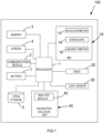
- FIG 1 is a schematic logical diagram of a portable device 100 that may implement the present invention.
- the portable device 100 is a smart phone, but it will be appreciated that the invention may be implemented on a range of devices such as wearable devices (e.g. smart watches and other jewellery), tablets, laptop computers etc.
- FIG. 1 shows the relevant components of the smart phone 100, which includes a processor 1, communications module 2, memory 3, screen 4, local storage 5 (non-volatile memory) and a battery 7.
- the communications module 2 comprises components necessary for wireless communication, such as a receiver, transmitter, antenna, local oscillator and signal processor.
- the device 100 also comprises an inertial measurement unit (IMU) 10, which here includes an accelerometer 12, a gyroscope 14 and a magnetometer 16.
- IMU inertial measurement unit
- the accelerometer is configured to measure the acceleration of the device; the gyroscope is configured to measure the rotation rate of the device, and the magnetometer is configured to measure the strength and direction of the local magnetic field, and hence the compass heading of the device 100.
- the accelerometer, gyroscope and magnetometer may be MEMs devices, which are typically tri-axial devices, where each orthogonal axis comprises a separate sensor. Other inertial sensors may be included in such an IMU.
- the device 100 further comprises a GNSS sensor 20, such as a GPS or GLONASS sensor (or both), and a light sensor 30.
- GNSS sensor 20 such as a GPS or GLONASS sensor (or both)
- GLONASS sensor or both
- light sensor 30 In other embodiments, other sensors may be used, examples of which have been discussed above.
- Each of the communications module 2, memory 3, screen 4, local storage 5, battery 7, IMU 10, GNSS sensor 20 and light sensor 30 is in logical communication with the processor 1.
- the processor 1 is also in logical communication with Navigation Solution Unit (NSU) 40, which is operable to obtain data from the device sensors and determine from said data, amongst other metrics, the position and velocity of the device.
- NSU Navigation Solution Unit
- the evolution of the metric of interest is the position of the device 100, i.e. its trajectory over time.
- the NSU 40 may be implemented in hardware, firmware, software, or a combination thereof.
- a solution may be provided by performing, at each time instance in the time interval T 1 to T 2 , single integration of the data from the rate gyroscope 14 to determine device attitude and double integration (while correcting for gravity) of the data obtained from the accelerometer sensor 12 in order to obtain position data.
- single integration of the data from the rate gyroscope 14 to determine device attitude and double integration (while correcting for gravity) of the data obtained from the accelerometer sensor 12 in order to obtain position data.
- double integration while correcting for gravity
- GNSS sensors may provide accurate position data when the device has a clear line of sight to the satellite constellation, position data from such sensors is subject to large errors (or may not be available at all) when no direct line of sight is available, such as when the user is inside a building or travelling through an "urban canyon".
- Figure 2 schematically illustrates how the present invention overcomes these problems in order to provide an accurate and reliable trajectory of the device between the time instances T 1 and T 2 .
- Box 210 in Figure 2 schematically represents data obtained by the sensors of the IMU 10, GNSS sensor 20 and light sensor 30 over the time period between T 0 (for example when the user turned the smart phone on in the morning) to time T 3 , which in the current example is the present time.
- this time period between T 0 and T 3 will be referred to as the second time period 210.
- box 220 schematically represents data obtained by the sensors of the IMU 10, GNSS sensor 20 and light sensor 30 over the time period between T 1 and T 2 which, for the purposes of this discussion, will be referred to as the first time period.
- the evolution of the metric of interest (position) is being measured between time instances T 1 and T 2 corresponding to the first time period, although this is not necessarily the case.
- the evolution of the position may be desired to be determined between the time instances T 0 and T 2 .
- the data obtained in the first time period (the first data) and the data obtained in the second time period (the second data) are provided to the NSU 40 which calculates the desired solution, in this case the trajectory of the device between time instances T 1 and T 2 .
- the solution is constrained by both the first data and the second data, and a motion model of the device between time instances T 1 and T 2 .
- the motion model represents the general motion of the device, and preferably comprises three components: a position context, a motion context and at least one parameter that quantitatively represents the motion of the device.
- the position context is the context in which the smart phone is being supported, and may comprise the attitude of the device, for example a heading to direction-of-motion offset. More generally, this can be used to infer the mode in which the device is being carried, which in the case of a smart phone may be in a pocket, beside the ear, in the user's hand swinging by his side, being held in front of the user's face etc.
- the motion context may generally describe the mode by which the user of the smart phone (and hence the smart phone itself) is moving, for example walking, running, crawling, cycling etc.
- the at least one parameter quantitatively describes an aspect of the motion, for example, a step length or speed of the user.
- the solution is constrained by the first data, second data and the motion model, this means that erroneous data obtained from the sensors may be corrected for in providing the position solution.
- the motion model comprises a motion context of "walking” and a position context of "in a user's pocket”
- any data obtained by, say, the GNSS sensor that does not align with the motion model for example a spurious data event that would not be possible by walking, such as a sudden and large change in position
- the motion model may be pre-selected by a user of the smart phone, for example through interaction with an appropriate graphical user interface (GUI) presented to the user via screen 4.
- GUI graphical user interface
- the user may decide to go for a run, and select a motion model that comprises a motion context of "running".
- the solution provided by the NSU 40 is constrained by the first data, second data and the "running" motion model.
- the first and/or second data may be used to automatically select, by an analysis module 42 of the NSU 40, a motion model for use in generating the position solution.
- the second data may be analysed by the analysis module 42, and the data from the accelerometer and gyroscope sensors used to determine a current motion and/or position context.
- the accelerometer 12 may determine a step cadence of the user and determine that the motion context is "walking", and furthermore that the step length of the user is 0.8m.
- the light sensor 30 may detect minimal or no light during the time period between T 0 and T 3 , and it can therefore be inferred that the smart phone is in an enclosed space such as a pocket or a bag if the time is during daylight hours. Therefore, the second time period can be thought of as providing a context under which the data from the first time period is processed to provide the location solution.
- the first data may also be used to select a motion model automatically.
- the method of the present invention takes advantage of the fact that a user of a portable device such as a smart phone 100 is likely to make numerous such journeys. Therefore, the motion model parameters for a particular user and device/sensor combination may be automatically learned by machine learning algorithms and refined over a plurality of such journeys spanning a wide range of motion and position contexts. For example, it may be determined that after a plurality of journeys, a reliable step length for the user of a smart phone is 0.75m rather than the initially-determined 0.8m, thereby providing more accurate navigation solutions.
- the motion models and their various parameters may be stored in the local storage 5 on the device, or by other addressable storage means (e.g. through use of a client-server system), and indexed by position context and/or motion context. Subsequently, a stored motion model and its corresponding parameters may be automatically selected from the addressable storage when a particular motion and/or position context is determined.
- a user may use more than one device, for example a smart phone and a wearable device such as a smart watch.
- the motion model and associated parameters may be further indexed by device and/or user, such that, in general, a motion model appropriate for a device and its current user may be selected automatically.
- the data obtained during the first 220 and second 210 time periods is analysed by the analysis module 42 of the NSU 40 during the determination of the device trajectory between time instances T 1 and T 2 .
- Such analysis advantageously allows for the assessment of the reliability and accuracy of the data obtained during the first and second time periods, in order to provide improved navigation solutions as compared to state-of-the-art systems that instead rely on instantaneous estimates.
- the second time instance T 2 is in fact in the past with respect to the present time, which here is T 3 .
- Instantaneous position data is not always required, and indeed in many cases users of a device would be willing to forego instantaneous results for more accurate position data.
- the time lag between T 2 and T 3 may be of the order of 1s, or longer.
- Such analysis as performed by the analysis module 42 may comprise self-consistency analysis (analysing the data obtained by a sensor across the respective time period) and cross-reference analysis, where the data from one sensor is compared with the data from another sensor and/or the motion model.
- the analysis performed by the analysis module may comprise analysing the obtained data forward and/or backwards in time, or as a batch process.
- the analysis performed by the analysis module 42 may comprise processing the obtained data forwards and backwards in time, which allows any asymmetries in them to be used in determining their reliability and accuracy.
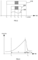
- Figure 3 schematically illustrates one-dimensional position data obtained by the GNSS sensor 20.
- the plotted change in position between the time instances T A and T B is caused by erroneous position data.
- the gradual change in position over the time period A may initially be seen as a possible "allowed" motion of the device (the allowed motions being constrained, for example, by the current motion model and/or measurements from the IMU).
- the erroneous GNSS position data from time period A is used to generate the navigation solution.
- the rapid change in position over time period B falls outside the allowed range of motion of the device, indicating there is a potential problem with the GNSS position data.
- the analysis may comprise iteratively processing the obtained data forward and/or backwards in time.
- confidence thresholds applied to an initial pass of the data may be such that all of the obtained data is allowed to be used for the navigation solution provided by the NSU 40.
- these data may include erroneous results such as the GNSS data obtained between time instance T A and T B depicted in Figure 3 ; however, it is important not to lose data that may represent the actual motion taken by the device.
- those from particular time periods (such as between T A and T B ) may not meet a new confidence threshold determined after the first pass, and are therefore ignored or corrected for.
- Confidence thresholds may be set initially according to the known statistical noise properties of the device sensors, or from information derived from other sensors.
- the accelerometer 12 may provide acceleration information in order to set thresholds on the expected variation in the GNSS frequency measurements during dynamic motions.
- the biases on the accelerometer may be known more accurately (for example, zero velocity update analysis may be performed during an initial analysis which reveals bias information). This means that the acceleration data is more accurate and reliable and therefore the confidence threshold on the expected frequency variation can be tighter (i.e. smaller variation). As a result, any error in frequency measurement that was allowed during the first pass of the data may now be ignored on the second pass due to the tighter (more confident) confidence thresholds.
- the initial confidence thresholds may be such that the GNSS data obtained between time instances T A and T B are seen as being consistent with the "allowed" motion of the device from the motion model.
- better estimates of the IMU 10 biases are determined, which can be used on subsequent passes of the data to provide more accurate IMU data and, consequently, tighter confidence thresholds for other sensor data.
- the GNSS position data between time instances T A and T B might now be found to be inconsistent with the more tightly constrained allowed motion of the device, and, as a result, be filtered out of (or assigned lower confidence in) the final trajectory solution.
- Confidence thresholds and the related analyses forwards and backwards in time may be applied to sensor data as described, and also to derived data and metrics of interest, including platform states, pose, and derived or latent variables such as sensor biases and calibration parameters.
- the second time period 210 is illustrated as extending between time instance T 0 and T 3 , and the first time period 220 as extending between T 1 and Tz.
- the durations of the first and second time periods are chosen so as to allow for optimal assessment by the analysis module 42 of the reliability and accuracy of the data obtained from the device sensors.
- the durations of the first and/or second time periods may be dynamically changed in response to the assessment by the analysis module.
- the second time period may be extended because of the erroneous data between time periods T A and T B , such that the extended time period allows for a more reliable interpretation of the data (for example so as to automatically select a motion model).
- Figure 4 schematically illustrates the evolution of the position of the smart phone 100 as determined between time instances T 1 and T 2 .
- the hatched boxes 100a, 100b, 100c, 100d, 100e, 100f represent time periods in which the absolute position of the device 100 has been determined with high confidence ("confident sections"), for example because of the availability of high quality GNSS data.
- the orientations of the confident sections also indicate the orientation of the device (e.g. position context) at that time period.
- the line 400 between the confident sections illustrates the potential trajectory of the device (i.e. the evolution of its position) as determined by the NSU 40.
- the time instances T A and T B are illustratively shown as a time period where the GNSS data were deemed to be too unreliable for determining the absolute position of the device, as has been explained above in relation to Figure 3 .
- Other metrics may be used to invoke the rejection (or reduction in confidence) of GNSS data, for example the number of satellites in use being fewer than a predetermined number, the signal strength of the GNSS data being below a predetermined threshold etc.
- the GNSS data when the GNSS data are analysed, if an event that is deemed to be unreliable is found (such as region B in Figure 3 ), then the GNSS data may be deemed unreliable for a certain time period before and after the "flagged" event, as the error in the data from the GNSS sensor may increase gradually rather than abruptly. For example, again referring to Figure 3 , the GNSS trace would be flagged as unreliable from time instant T A rather than from the start of time period T B .
- the data obtained in the confident sections are analysed and used to determine biases in the accelerometer 12, gyroscope 14 and magnetometer 16 sensors, calculate step length parameters of the motion model, and determine the direction-of-motion to heading offset, such that the data obtained from the IMU sensors, together with the motion model, may be used to determine the trajectory of the device accurately and reliably between the confident hatched regions.
- data obtained from the accelerometer 12, gyroscope 14 and magnetometer 16 during the time periods between the confident sections may be used in combination with multiple estimates of one or more parameters to determine a plurality of possible trajectories, and the trajectory that best aligns with the confident sections may be used.
- a plurality of direction-of-motion to heading-offset estimates may be used to generate trial trajectories during the low-confidence time periods, with the optimal trajectory being chosen as that which best aligns with the end-points of the trajectory in the high-confidence time periods.
- the trajectory between the confident sections may also be constrained using prior information obtained from a map to help determine which of the plurality of trajectories is the most likely. For example, if one of the possible trajectories involved crossing a river where no bridge was located, that particular trajectory could be ruled out; or if the map data indicates that a pedestrian would most likely travel along a straight path while the navigation solution shows a curved trajectory, this could be used to identify and correct a yaw-axis gyroscope bias.
- a least-squares fit of the entire trajectory (or piecewise fitting of sections of the trajectory) constrained by the data from the confident sections may be carried out.
- the second time period may extend into the future with respect to the first time period (and the second time instant T 2 ).
- data from the future with respect to T 2 is used to constrain the solution.
- This provides a more accurate determination of the evolution of the metric of interest, as constraints may be interpolated for future time periods with respect to the second time instance T 2 , rather than simply extrapolated.
- the extension of the second time period into the future with respect to the second time instance T 2 allows for a more accurate context, or "overall picture" of the data from which the evolution of the metric of interest is to be determined.
- the second time instance T 2 may be at, or within a small interval behind, present time, as schematically illustrated in Figure 5 .
- the relative positions of the second time period 210 and first time period 220 are also shown, with both time periods ending at time T 2 and only extending into the past with respect to T 2 .
- the trajectory of the device may be provided to the user in near-real-time, with the solution for the present time only constrained by past data.
- position solutions for previous times may be continually updated as new data are obtained.
- time instance T 2 both the first and second time periods extend into the future with respect to T 1 , and therefore at T 2 , a more accurate and reliable position of the device at T 1 may be determined as compared to the solution determined within the small interval behind at the time instance T 1 itself.
- the invention provides for near-real-time determination of the evolution of a metric of interest, as well as an improved determination of said evolution over time as more data are obtained.
- Figure 6 is a flow diagram 600 outlining the main steps of one embodiment of the invention.
- a user of the device preselects a motion model, typically by interaction with a suitable GUI via a screen of the device.
- a motion model may comprise a motion context, a position context and at least one quantitative parameter describing the motion.
- the user may pre-select at least one of these components. For example, the user may simply select a motion model having a motion context of "running".
- the NSU 40 obtains data from the first time period, and at step 603 obtains data from the second time period.
- the NSU 40 may obtain the data from the first and second time periods substantially simultaneously. In other embodiments the data from the second time period may be obtained before the data from the first time period.
- the first and second data are analysed by the analysis module 42, as described above, and at step 605, the NSU 40 determines the evolution of the metric of interest between first and second time instances.
- the motion model is shown as being pre-selected before the obtaining of data. However, it will be appreciated that the motion model may be selected by the user after the obtaining of the data.
- Figure 7 is a flow diagram 700 outlining the main steps of a further embodiment of the invention, in this case where the motion model is automatically selected from analysis of the first and second data.
- the NSU 40 obtains data from the first time period
- at step 702 obtains data from the second time period.
- steps 701 and 702 may in some cases occur substantially simultaneously or in reverse order.
- step 703 the first and second data are analysed by the analysis module 42.
- step 704 from the analysis performed at step 703, the motion and/or position context of the device is determined.
- the quantitative motion model parameter may comprise an estimate of the step length of the user for example. As has been discussed above, advantageously such a parameter may have been refined during previous analyses of data obtained by the device for the user.
- step 705 If, at step 705, it is determined that no corresponding motion model parameter exists, then the method moves to optional step 706 where the determined motion and/or position context is used to determine at least one parameter associated with the motion of the device. Optionally, this may be stored in addressable storage (step 707), indexed by the determined motion and/or position context and the identity of the device. Subsequently, at step 709 the NSU 40 determines the evolution of the metric of interest between time instances T 1 and T 2 , with the evolution constrained by the first data, second data and motion model.
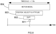
- FIG 8 is a schematic overview of how data from at least one sensor may be used to determine a navigation solution, for example for the smart phone 100 described above.
- Box 801 schematically represents the navigation solution generated by the NSU 40, at time instance T 1 , which here is at, or within a small interval behind, the present time.
- the navigation solution of the NSU is based on data from the IMU, the sensors of which may have sampling rates in the region of -100-1000 samples per second, and so the time period of box 801 may be of the order of -1-10ms.
- this "instantaneous" data obtained from an IMU would simply be used to output the navigation solution for that instant in time, and would therefore be subject to large error drift.
- the present invention may utilise data obtained from past and future time periods with respect to the NSU/IMU time instance T 1 in order to constrain the navigation solution at that time instance.
- Information from any of the boxes 801 to 804 may be analysed intra- and inter-box using a variety of methods in order to optimally filter and combine all of the available data, thus resulting in an improved navigation solution.
- box 802, labelled "ZUPT” represents data obtained by the IMU, and which has been analysed to determine whether or not the IMU was stationary at time instances during the time interval represented by box 802. Periods of detected zero velocity may be used, for example, to reset the velocity measurement being tracked by the NSU, or to determine biases in the inertial sensors of the IMU which may then be used to constrain the NSU solution at time instance T 1 .
- Box 803 may represent data obtained from a GNSS sensor that can be used to provide position and velocity data to further constrain the NSU solution. Additionally, information from box 802 may be used to filter out GNSS data in box 803 that is in violation of a confidently determined zero velocity condition. Attitude data may be obtained from an accelerometer and/or a gyroscope and/or magnetometer sensor.
- a motion model schematically illustrated at box 804 may have been pre-selected or automatically determined (for example through analysis of the raw IMU data, or from the position, velocity and attitude data).
- the motion model may include one or more parametric models describing some aspect of the user's motion. Analyses of sensor data contained in one or more of the boxes 801 to 804 may be performed to extract values subsequently used as input to such parametric models. For example, stepping cadence may be extracted from accelerometer data, and subsequently input to a function modelling pedestrian step length. As has been described above, the motion model at box 804 may be used to aid filtering of input sensor data and constrain the navigation solution.
- Figure 8 illustrates boxes 802, 803 and 804 as having different sizes (i.e. time periods), but this does not necessarily have to be the case and is for the purposes of illustration only.
- the data obtained and used to constrain the NSU solution at time instance T 1 have been obtained over longer time periods, and extend into both the past and future, with respect to time instance T 1 .
- the evolution of the metric of interest may be determined between first and second time instances by combining the positioning solution obtained at a plurality of such time instances.
- FIG. 8 the diagram of Figure 8 is for illustrative purposes only, and the boxes may represent different sensor data streams and analyses.
- a first platform may be a smart phone carried by a user and the second platform may be a smart watch worn by the user.
- both platforms here can be thought of as freely-moving sensor sets that provide independent measurements about the user.
- the evolution of that metric of interest can be reliably inferred for the user (i.e. the trajectory of the user).
- comparisons between the data obtained on the different platforms may be performed. For example, data obtained from an inertial sensor of the smart watch may be cross-referenced with data obtained from a GNSS sensor of the smart phone.
- a vehicle has sensors mounted onto its chassis (the first platform) which measure the vehicle's acceleration and rate-of-turning.
- the driver carries a smartphone in his pocket (the second platform) which has a built-in GNSS receiver, as well as sensors measuring acceleration, rate of turning etc. Data obtained from all of these sensors are analysed together using the methods outlined above to determine the trajectory of the driver's pocket and/or the vehicle with the lowest uncertainty.
Landscapes
- Engineering & Computer Science (AREA)
- Radar, Positioning & Navigation (AREA)
- Remote Sensing (AREA)
- Physics & Mathematics (AREA)
- General Physics & Mathematics (AREA)
- Automation & Control Theory (AREA)
- Computer Networks & Wireless Communication (AREA)
- Electromagnetism (AREA)
- Navigation (AREA)
Applications Claiming Priority (3)
| Application Number | Priority Date | Filing Date | Title |
|---|---|---|---|
| GB1717632.2A GB2567845B (en) | 2017-10-26 | 2017-10-26 | A method and system for combining sensor data |
| US15/894,841 US11035673B2 (en) | 2017-10-26 | 2018-02-12 | Method and system for combining sensor data |
| PCT/GB2018/053105 WO2019081944A1 (en) | 2017-10-26 | 2018-10-26 | METHOD AND SYSTEM FOR COMBINING SENSOR DATA |
Publications (2)
| Publication Number | Publication Date |
|---|---|
| EP3701286A1 EP3701286A1 (en) | 2020-09-02 |
| EP3701286B1 true EP3701286B1 (en) | 2024-03-27 |
Family
ID=60580106
Family Applications (1)
| Application Number | Title | Priority Date | Filing Date |
|---|---|---|---|
| EP18797058.7A Active EP3701286B1 (en) | 2017-10-26 | 2018-10-26 | A method and system for combining sensor data |
Country Status (5)
| Country | Link |
|---|---|
| US (3) | US11035673B2 (zh) |
| EP (1) | EP3701286B1 (zh) |
| CN (1) | CN111263900B (zh) |
| GB (1) | GB2567845B (zh) |
| WO (1) | WO2019081944A1 (zh) |
Families Citing this family (13)
| Publication number | Priority date | Publication date | Assignee | Title |
|---|---|---|---|---|
| EP3405931B1 (en) * | 2016-01-20 | 2020-04-22 | Koninklijke Philips N.V. | Occupancy sensing system and sensing method |
| US10859713B2 (en) * | 2017-01-04 | 2020-12-08 | Qualcomm Incorporated | Position-window extension for GNSS and visual-inertial-odometry (VIO) fusion |
| GB2567845B (en) * | 2017-10-26 | 2023-02-01 | Focal Point Positioning Ltd | A method and system for combining sensor data |
| US11167743B2 (en) * | 2018-04-03 | 2021-11-09 | AgJunction, LLC | Automatic pitch mounting compensation in an automatic steering system |
| CN110109976B (zh) * | 2019-05-15 | 2021-09-10 | 成都四方伟业软件股份有限公司 | 数据处理方法、装置、系统及存储介质 |
| US11709279B2 (en) * | 2019-08-14 | 2023-07-25 | Apple Inc. | Device orientation initialization |
| WO2021033113A1 (en) * | 2019-08-16 | 2021-02-25 | Thermo King Corporation | Environmental sensor for transport refrigeration |
| US11290183B2 (en) * | 2020-02-10 | 2022-03-29 | SA Photonics, Inc. | Feed-forward control of free space optical communication system based on inertial measurement unit |
| CN111637889A (zh) * | 2020-06-15 | 2020-09-08 | 中南大学 | 基于惯导和激光雷达三点测距的掘进机定位方法及系统 |
| US20210396524A1 (en) | 2020-06-17 | 2021-12-23 | Astra Navigation, Inc. | Generating a Geomagnetic Map |
| US20240167819A1 (en) | 2020-06-17 | 2024-05-23 | Astra Navigation, Inc. | Correlating Overlapping Magnetic Measurement Data from Multiple Magnetic Navigation Devices and Updating a Geomagnetic Map with that Data |
| WO2022261539A1 (en) * | 2021-06-11 | 2022-12-15 | The Regents Of The University Of California | Smartphone-based inertial odometry |
| CN113899363B (zh) * | 2021-09-29 | 2022-10-21 | 北京百度网讯科技有限公司 | 车辆的定位方法、装置及自动驾驶车辆 |
Family Cites Families (22)
| Publication number | Priority date | Publication date | Assignee | Title |
|---|---|---|---|---|
| US7827000B2 (en) * | 2006-03-03 | 2010-11-02 | Garmin Switzerland Gmbh | Method and apparatus for estimating a motion parameter |
| CN101815314A (zh) * | 2009-02-20 | 2010-08-25 | 华为技术有限公司 | 发现无线网络问题的方法、装置及系统 |
| US20110238308A1 (en) * | 2010-03-26 | 2011-09-29 | Isaac Thomas Miller | Pedal navigation using leo signals and body-mounted sensors |
| US9579048B2 (en) * | 2012-07-30 | 2017-02-28 | Treefrog Developments, Inc | Activity monitoring system with haptic feedback |
| US9161172B2 (en) * | 2012-11-06 | 2015-10-13 | Qualcomm Incorporated | Map-based adaptive sampling of orientation sensors for positioning |
| US20150185045A1 (en) * | 2013-12-30 | 2015-07-02 | Aliphcom | Dynamic calibration of relationships of motion units |
| FR3026216B1 (fr) * | 2014-09-18 | 2016-12-23 | Dassault Aviat | Systeme d'assistance au pilotage d'une plate-forme, et procede associe |
| DE102014219148A1 (de) * | 2014-09-23 | 2016-03-24 | Robert Bosch Gmbh | Verfahren und Vorrichtung zum Erstellen eines Bewegungsmodells eines Straßenverkehrsteilnehmers |
| FR3028031B1 (fr) * | 2014-10-29 | 2019-09-20 | Safran Electronics & Defense | Procede d'estimation d'un etat de navigation contraint en observabilite |
| US9719787B2 (en) * | 2015-02-26 | 2017-08-01 | Invensense, Inc. | Method and system for multiple pass smoothing |
| CN107923749B (zh) * | 2015-07-27 | 2020-11-24 | 飞利浦照明控股有限公司 | 用于检测地面位置变化的系统和方法 |
| US9743253B2 (en) * | 2015-08-27 | 2017-08-22 | Glopos Fzc | Method and arrangement for locating a mobile device |
| US10126134B2 (en) * | 2015-12-21 | 2018-11-13 | Invensense, Inc. | Method and system for estimating uncertainty for offline map information aided enhanced portable navigation |
| EP3211371B1 (en) * | 2016-02-26 | 2020-11-11 | InvenSense, Inc. | Method and system for multiple pass smoothing |
| US11808865B2 (en) | 2016-03-24 | 2023-11-07 | Focal Point Positioning Limited | Method and system for calibrating a system parameter |
| US10321430B2 (en) | 2016-03-24 | 2019-06-11 | Focal Point Positioning Ltd. | Method, apparatus, computer program, chip set, or data structure for correlating a digital signal and a correlation code |
| US9780829B1 (en) | 2016-03-24 | 2017-10-03 | Focal Point Positioning Ltd. | Method, apparatus, computer program, chip set, or data structure for correlating a digital signal and a correlation code |
| US9581467B1 (en) * | 2016-05-13 | 2017-02-28 | Google Inc. | Orientation estimation based on backward-forward bayesian filtering |
| GB2564406B (en) | 2017-07-06 | 2022-09-07 | Focal Point Positioning Ltd | Method and system for correcting the frequency or phase of a local signal generated using a local oscillator |
| US10983199B2 (en) * | 2017-08-11 | 2021-04-20 | Zoox, Inc. | Vehicle sensor calibration and localization |
| GB2566731A (en) | 2017-09-25 | 2019-03-27 | Focal Point Positioning Ltd | System for determining a physical metric such as position |
| GB2567845B (en) * | 2017-10-26 | 2023-02-01 | Focal Point Positioning Ltd | A method and system for combining sensor data |
-
2017
- 2017-10-26 GB GB1717632.2A patent/GB2567845B/en active Active
-
2018
- 2018-02-12 US US15/894,841 patent/US11035673B2/en active Active
- 2018-10-26 WO PCT/GB2018/053105 patent/WO2019081944A1/en unknown
- 2018-10-26 EP EP18797058.7A patent/EP3701286B1/en active Active
- 2018-10-26 CN CN201880069077.0A patent/CN111263900B/zh active Active
-
2021
- 2021-05-10 US US17/315,461 patent/US11815355B2/en active Active
-
2023
- 2023-10-06 US US18/377,380 patent/US20240027194A1/en active Pending
Also Published As
| Publication number | Publication date |
|---|---|
| US20210278216A1 (en) | 2021-09-09 |
| GB201717632D0 (en) | 2017-12-13 |
| US20240027194A1 (en) | 2024-01-25 |
| US11815355B2 (en) | 2023-11-14 |
| GB2567845A (en) | 2019-05-01 |
| WO2019081944A1 (en) | 2019-05-02 |
| US11035673B2 (en) | 2021-06-15 |
| GB2567845B (en) | 2023-02-01 |
| CN111263900A (zh) | 2020-06-09 |
| KR20200078507A (ko) | 2020-07-01 |
| CN111263900B (zh) | 2023-12-19 |
| EP3701286A1 (en) | 2020-09-02 |
| US20190128673A1 (en) | 2019-05-02 |
Similar Documents
| Publication | Publication Date | Title |
|---|---|---|
| EP3701286B1 (en) | A method and system for combining sensor data | |
| US20210254979A1 (en) | Method of estimating a metric of interest related to the motion of a body | |
| US11927447B2 (en) | Method for accelerometer-assisted navigation | |
| US9360323B2 (en) | Systems and methods for estimating movements of a vehicle using a mobile device | |
| EP3201633B1 (en) | Methods and systems for vertical trajectory determination and automatic jump detection | |
| JP6674791B2 (ja) | 混雑度推定方法、人数推定方法、混雑度推定プログラム、人数推定プログラム、および人数推定システム | |
| US9234767B2 (en) | Running condition detection device, running condition detection method, and recording medium | |
| US11686862B2 (en) | Inferring vehicle location and movement using sensor data fusion | |
| TWI524083B (zh) | 衛星導航接收機、設備和定位方法 | |
| JP5953677B2 (ja) | 情報処理装置、情報処理方法、プログラム、及び記録媒体 | |
| JP2012233800A (ja) | マルチセンサ判定装置及びプログラム | |
| KR102666648B1 (ko) | 센서 데이터를 결합하기 위한 방법 및 시스템 |
Legal Events
| Date | Code | Title | Description |
|---|---|---|---|
| STAA | Information on the status of an ep patent application or granted ep patent |
Free format text: STATUS: UNKNOWN |
|
| STAA | Information on the status of an ep patent application or granted ep patent |
Free format text: STATUS: THE INTERNATIONAL PUBLICATION HAS BEEN MADE |
|
| PUAI | Public reference made under article 153(3) epc to a published international application that has entered the european phase |
Free format text: ORIGINAL CODE: 0009012 |
|
| STAA | Information on the status of an ep patent application or granted ep patent |
Free format text: STATUS: REQUEST FOR EXAMINATION WAS MADE |
|
| 17P | Request for examination filed |
Effective date: 20200513 |
|
| AK | Designated contracting states |
Kind code of ref document: A1 Designated state(s): AL AT BE BG CH CY CZ DE DK EE ES FI FR GB GR HR HU IE IS IT LI LT LU LV MC MK MT NL NO PL PT RO RS SE SI SK SM TR |
|
| AX | Request for extension of the european patent |
Extension state: BA ME |
|
| RIN1 | Information on inventor provided before grant (corrected) |
Inventor name: CROCKETT, ROBERT MARK Inventor name: DUFFETT-SMITH, PETER Inventor name: FARAGHER, RAMSEY MICHAEL |
|
| DAV | Request for validation of the european patent (deleted) | ||
| DAX | Request for extension of the european patent (deleted) | ||
| STAA | Information on the status of an ep patent application or granted ep patent |
Free format text: STATUS: EXAMINATION IS IN PROGRESS |
|
| 17Q | First examination report despatched |
Effective date: 20210903 |
|
| RAP3 | Party data changed (applicant data changed or rights of an application transferred) |
Owner name: FOCAL POINT POSITIONING LTD. |
|
| REG | Reference to a national code |
Ref country code: DE Ref legal event code: R079 Ref document number: 602018067224 Country of ref document: DE Free format text: PREVIOUS MAIN CLASS: G01S0019480000 Ipc: G01C0022000000 Ref country code: DE Ref legal event code: R079 Free format text: PREVIOUS MAIN CLASS: G01S0019480000 Ipc: G01C0022000000 |
|
| GRAP | Despatch of communication of intention to grant a patent |
Free format text: ORIGINAL CODE: EPIDOSNIGR1 |
|
| STAA | Information on the status of an ep patent application or granted ep patent |
Free format text: STATUS: GRANT OF PATENT IS INTENDED |
|
| RIC1 | Information provided on ipc code assigned before grant |
Ipc: G01C 21/12 20060101ALI20230824BHEP Ipc: G01S 19/48 20100101ALI20230824BHEP Ipc: G01C 21/16 20060101ALI20230824BHEP Ipc: G01S 19/49 20100101ALI20230824BHEP Ipc: G01S 19/39 20100101ALI20230824BHEP Ipc: G01S 5/00 20060101ALI20230824BHEP Ipc: G01C 22/00 20060101AFI20230824BHEP |
|
| INTG | Intention to grant announced |
Effective date: 20230919 |
|
| P01 | Opt-out of the competence of the unified patent court (upc) registered |
Effective date: 20231024 |
|
| GRAS | Grant fee paid |
Free format text: ORIGINAL CODE: EPIDOSNIGR3 |
|
| GRAA | (expected) grant |
Free format text: ORIGINAL CODE: 0009210 |
|
| STAA | Information on the status of an ep patent application or granted ep patent |
Free format text: STATUS: THE PATENT HAS BEEN GRANTED |
|
| AK | Designated contracting states |
Kind code of ref document: B1 Designated state(s): AL AT BE BG CH CY CZ DE DK EE ES FI FR GB GR HR HU IE IS IT LI LT LU LV MC MK MT NL NO PL PT RO RS SE SI SK SM TR |
|
| REG | Reference to a national code |
Ref country code: GB Ref legal event code: FG4D |
|
| REG | Reference to a national code |
Ref country code: CH Ref legal event code: EP |
|
| REG | Reference to a national code |
Ref country code: DE Ref legal event code: R096 Ref document number: 602018067224 Country of ref document: DE |
|
| REG | Reference to a national code |
Ref country code: IE Ref legal event code: FG4D |