EP3701152B1 - Verfahren und vorrichtung zur bewahrung eines pumpsystems im betriebszustand - Google Patents
Verfahren und vorrichtung zur bewahrung eines pumpsystems im betriebszustand Download PDFInfo
- Publication number
- EP3701152B1 EP3701152B1 EP18789158.5A EP18789158A EP3701152B1 EP 3701152 B1 EP3701152 B1 EP 3701152B1 EP 18789158 A EP18789158 A EP 18789158A EP 3701152 B1 EP3701152 B1 EP 3701152B1
- Authority
- EP
- European Patent Office
- Prior art keywords
- pump
- pumping system
- motor
- pumping
- flow rate
- Prior art date
- Legal status (The legal status is an assumption and is not a legal conclusion. Google has not performed a legal analysis and makes no representation as to the accuracy of the status listed.)
- Active
Links
Images

Classifications
-
- F—MECHANICAL ENGINEERING; LIGHTING; HEATING; WEAPONS; BLASTING
- F04—POSITIVE - DISPLACEMENT MACHINES FOR LIQUIDS; PUMPS FOR LIQUIDS OR ELASTIC FLUIDS
- F04D—NON-POSITIVE-DISPLACEMENT PUMPS
- F04D7/00—Pumps adapted for handling specific fluids, e.g. by selection of specific materials for pumps or pump parts
- F04D7/02—Pumps adapted for handling specific fluids, e.g. by selection of specific materials for pumps or pump parts of centrifugal type
- F04D7/04—Pumps adapted for handling specific fluids, e.g. by selection of specific materials for pumps or pump parts of centrifugal type the fluids being viscous or non-homogenous
-
- F—MECHANICAL ENGINEERING; LIGHTING; HEATING; WEAPONS; BLASTING
- F04—POSITIVE - DISPLACEMENT MACHINES FOR LIQUIDS; PUMPS FOR LIQUIDS OR ELASTIC FLUIDS
- F04D—NON-POSITIVE-DISPLACEMENT PUMPS
- F04D13/00—Pumping installations or systems
- F04D13/02—Units comprising pumps and their driving means
- F04D13/06—Units comprising pumps and their driving means the pump being electrically driven
-
- F—MECHANICAL ENGINEERING; LIGHTING; HEATING; WEAPONS; BLASTING
- F04—POSITIVE - DISPLACEMENT MACHINES FOR LIQUIDS; PUMPS FOR LIQUIDS OR ELASTIC FLUIDS
- F04D—NON-POSITIVE-DISPLACEMENT PUMPS
- F04D15/00—Control, e.g. regulation, of pumps, pumping installations or systems
- F04D15/0077—Safety measures
-
- F—MECHANICAL ENGINEERING; LIGHTING; HEATING; WEAPONS; BLASTING
- F04—POSITIVE - DISPLACEMENT MACHINES FOR LIQUIDS; PUMPS FOR LIQUIDS OR ELASTIC FLUIDS
- F04D—NON-POSITIVE-DISPLACEMENT PUMPS
- F04D15/00—Control, e.g. regulation, of pumps, pumping installations or systems
- F04D15/0088—Testing machines
Definitions
- the invention is in the field of pumping, such as urban hydraulic pumping which is involved in the collection and transport of waste water as well as in the distribution of water.
- the invention relates more generally to the problems of managing water pumping stations comprising one or more pumping systems.
- a first type of actors are pump manufacturers.
- the latter benefit from detailed knowledge of the operation of their product and can thus finely detect operating drifts that can lead to pump failures.
- the management systems proposed by pump manufacturers are not, or are poorly, adapted to pumps from other manufacturers, nor to the pumping station as a whole, when it includes several pumps of different origin and manufacture for which it is necessary to monitor several different parameters such as hydraulic or electrical parameters.
- a third type of actor are the manufacturers of components used in pumps and their motors. These components include bearings, seals, etc. Again, this type of actor is very specialized in its technical field and even if the systems it offers will detect a component failure very well, failures due to other components will not be detected.
- a fourth type of actors are service providers who will design generic pumping station management tools. These tools take into account all the components of the pumps and motors but they must be correctly configured by an operator specialized in programming and with a good knowledge of the systems making up the pumping station. The configuration of such tools requires knowledge that electromechanical operators specialized in the management of pumping stations do not have. In the same way, operators specialized in the configuration of management tools do not have a very in-depth knowledge of the operation of each piece of equipment in the pumping station.
- One objective of the invention is in particular to propose an automatic analysis tool for monitoring and analyzing the operation of the pumping station.
- This analysis tool also makes it possible to detect mechanical failures of the machines making up the pumping station, in particular the pumps and motors.
- the analysis tool proposes a causal assessment as well as preventive and curative actions to be carried out following detection of one or more failures on the various components of the pumping station. If the actions do not require intervention by an operator, the tool can transmit the appropriate instructions to the pumping station.
- US 2009204267 a device for maintaining the operational condition of a pumping system as defined by the preamble of claim 1.
- the present invention provides for this purpose a method of maintaining in operational condition a pumping system forming part of a pumping station as defined by claim 1.
- the method may include in particular a step of analyzing and interpreting the evolution of operating points of the pump and a step of analyzing and interpreting the evolution of operating points of the motor.
- the method may also include a step of monitoring the energy performance of the pumping system.
- Said method may also comprise a step of detecting a cavitation phenomenon.
- the water intake submersion control step can notably take into account a water height in the water intake, a flow rate drawn by the pump at the water intake, and physical description parameters of the water intake.
- the step of analysis and interpretation of the operation of the suction line can take into account the evolution over time of the following parameters: a pressure at the pump suction, a flow rate served by the pump, a current intensity called by the motor, an active power called by the motor, a total manometric height, an available NPSH.
- the invention further relates to a device as claimed.
- the invention makes it possible to automatically implement appropriate actions to prevent or resolve operating problems of the pumping station.
- variants of the invention comprising only a selection of features described or illustrated below, isolated from the other features described or illustrated (even if this selection is isolated within a sentence comprising these other features), if this selection of features is sufficient to confer a technical advantage or to differentiate the invention compared to the state of the prior art.
- This selection comprises at least one preferably functional feature without structural details and, alternatively or with only part of the structural details, if this part only is sufficient to confer a technical advantage or to differentiate the invention compared to the state of the prior art.
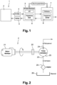
- FIG. 1 represents an example of a pumping station 1 comprising one or more pumping systems 2.
- the pumping system 2 comprises a pump, a motor, a water intake and an outlet pipe of the pump.
- the pumping system 2 may further comprise an inlet pipe connecting the pump to the water intake when the pump is not at least partially submerged in the fluid that it is to pump.
- the pumping system 2 further comprises sensors measuring parameters characteristic of the operation of each component of the pumping system 2.
- Each pumping system 2 is connected to an electrical cabinet 3 intended for managing the pumping system 2.
- the electrical cabinet 3 has the functions of monitoring and controlling the pumping system 2.
- the electrical cabinet 3 is part of the pumping station 1.
- the electrical cabinet 3 receives the various measurements, or inputs 4, made by the sensors of the pumping system 2 and transmits in particular to the pumping system 2 commands or outputs 5.
- the electrical cabinet 3 comprises at least one processor on which a local program 6 for managing the operation of the pumping system 2 is executed.
- the inputs 4 are taken into account by the local program 6.
- the electrical cabinet 3 then transmits the inputs 4 for processing to a supervision system 7.
- the supervision system 7 can monitor and control one or more pumping stations. In order to simplify the presentation, in the following we will only talk about one pumping station.
- the supervision system 7 is a remote server comprising at least one processor or computer which performs analysis processing on the inputs 4 by means of a computer program or central program 8.
- the central program 8 performs an analysis of the data and measurements coming from several pumping systems 2 in order to perform a monitoring function of the pumping station 1 as a whole.
- the supervision system 7 further comprises a database aggregating all of the physical characteristics of the pumping systems 2 and all of their components.
- the supervision system 7 is adapted to transmit instructions and commands to each pumping system 2 via each electrical cabinet 3.
- the electrical cabinet 3 adapts the instructions to the equipment to which said instructions are addressed in order to translate them into a signal that can be interpreted by the equipment.
- the equipment can for example be the pump, the motor or a valve.
- the electrical cabinet 3 can be configurable in particular via an API or Industrial Programmable Logic Controller.
- the configuration of the electrical cabinet 3 makes it possible to adapt this cabinet to different pumping systems 2, comprising for example equipment from different manufacturers.
- the electrical cabinet 3 can advantageously be programmed by an electromechanical operator who can enter thresholds and parameters to be taken into account in order to carry out the monitoring and supervision of each pumping system 2 of the pumping station 1. Said thresholds and parameters can thus be adapted to each piece of equipment.
- the thresholds and parameters can be transmitted to the supervision system 7 and stored in the database.
- the central program 8 uses the characteristics of the pumping station 1, the measurements made in real time as well as the parameters and thresholds entered by the operator in order to perform the monitoring function.
- the monitoring function performs an analysis of all of this information in order to detect a possible drift, linked to an anomaly that could lead to a breakdown or malfunction of the pumping station 1.
- the supervision system 7 analyzes all of the data in order to determine the cause of said drift according to rules defined according to the practices of the management field of pumping stations 1 as well as according to feedback from expert analysts of the causes of failure of pumping systems. These rules are also stored in the database. From the analyses carried out, the rules and the anomalies detected, the central program 8 can determine one or more actions, either preventive or curative, to be taken. These actions can be automatically transmitted to the electronic cabinet 3 in the form of commands and be transmitted to a human-machine interface for consultation by an operator.
- the operator can thus decide whether or not to carry out these actions or other operations.
- the operator can also, via the human-machine interface, enter commands to be implemented by the pumping station 1.
- the commands that can be implemented are, for example, stopping the pump and the motor, opening or closing a valve in the pumping station, instructions for changing the engine speed, etc.
- the pumping system 2 comprises at least one pump 20, an electric motor (21), a coupling device 22 of the motor 21 with the pump 20.
- the pump 20 is for example a dynamic pump which can be of the volumetric or rotodynamic type.
- the motor can be an asynchronous electric motor or a permanent magnet or variable reluctance synchronous type motor.
- the pump 20 comprises a fluid inlet 23 via a suction or intake pipe and a fluid outlet 24 via a discharge pipe.
- the inlet 23 is therefore connected to a suction pipe, itself connected to a water intake either via a strainer 25 or directly, without a strainer.
- the water suction can for example be done in a tank 26.
- the outlet 24, connected to a discharge pipe, supplies a system, not shown, for transferring water.
- the water transfer system can comprise a pipe or a network of pipes of different diameters and lengths.
- the pump may be immersed directly in the liquid.
- the pumping system does not include a suction line.
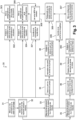
- a first step 31 of the method according to the invention is a step of updating the technical data and information on the pumping station as well as on the water transfer system that it serves, in the database of the supervision system 7.
- This information is for example the description of the pumping station 1 with all of its elements. In particular, it is important to provide the characteristics of the invisible parts of the pumping station 1, including their dimensions.
- the information describing the pumping station 1 it is also necessary to have plans and dimensions to locate the equipment of the pumping station 1 in relation to each other and in particular the pump in relation to the other equipment and the pump in relation to the measuring instruments, in particular hydraulic instruments.
- the information concerning the system served by the pumping station 1 is physical characteristics of said system served as well as the different elements composing it.
- the system served by the pumping station, or water transfer system may comprise one or more pipelines of different diameters and lengths.
- the information also comprises a description of the control modes of the pumping station 1, defined to satisfy the needs of the system served by the pumping station 1.
- the information on pumping station 1 makes it possible to construct a characteristic operating curve for pumping station 1 which represents a change in the water flow rate at the outlet of pumping station 1, as a function of the total manometric height.
- a second step 32 of the method according to the invention is a step of updating in the database information on the equipment of the pumping station 1 in particular on the pump 20, the motor 21 and the discharge and suction pipes and the water intake.
- the information on the equipment includes the performance curves of the pumps and motors.
- the first and second steps 31, 32 can be implemented when the pumping station 1 is put into service and then at each modification made to the pumping station 1 or the system that it serves, or even at each modification of a component of the pumping station 1.
- a third step 33 is a step of measuring or calculating physical and in particular hydraulic quantities, making it possible to characterize the current operation of the pumping system 2.
- the third step is carried out periodically during operation of the pumping station 1.
- the measurements carried out are dated and stored as and when in the database of the supervision system 7 with their date, thus constituting a history.
- Each hydraulic quantity is associated with an uncertainty and a range of variation of said quantity.
- a first hydraulic quantity is a pump flow rate which can be measured directly or calculated from other measurements.
- a second measured hydraulic quantity is a geometric height of the system supplied by pumping station 1, relative to said pumping station 1. This geometric height represents a minimum difference in level that the pump must overcome in order to supply the system that it serves.
- a third hydraulic quantity is a total manometric head or TMH.
- the manometric head can be defined as the sum of the geometric height and the pressure losses at the suction and discharge of the pump.
- a fourth hydraulic quantity is total dynamic head.
- Total dynamic head, or TDH can be defined as the sum of the total head and the dynamic pressure difference between the pump inlet and outlet.
- Mechanical quantities can also be taken into account such as vibration levels.
- a fourth step 34 is a step of calculating a service point or operating point, characteristic of the operation of the pump at a given time.
- the service point is determined from the hydraulic quantities calculated or measured during operation.
- the service point can be defined at a given time by a flow rate and a total manometric head.
- a fifth step 35 is a step of calculating physical quantities, notably electrical and mechanical.
- the electrical quantities measured are the intensity of the current drawn by the motor 21 and the supply voltage of the motor, as well as the variation range of these two electrical quantities.
- the fifth step 35 is also a step of determining the powers: active, reactive, apparent, distorting and their variation ranges. The uncertainties on the calculations of the different powers are also determined.
- Active power can be defined as the power useful for providing the work of the drive machine.
- Reactive power is defined as the power required to operate the machine, here, pump 20.
- Apparent power is defined as the power that actually flows through the equipment.
- Distorting power is a fourth power, present in circuits comprising electronic components that create non-linear loads and therefore harmonics.
- the distorting power is the power brought into play by the harmonic component.
- the fifth step 35 includes a determination of the different power factors, i.e. the cosine phi, the total power factor and the total harmonic distortion rate as well as the uncertainties on the different power factors.
- the total harmonic distortion rate is also called distortion power factor.
- the fifth step 35 is implemented cyclically during the operation of the pumping system 2.
- the measurements and the results of the calculations of these electrical quantities are stored in the database with a date and their measurement or calculation uncertainty as well as their variation range in order to constitute a history.
- a sixth step 36 is a step of determining an engine service point and its fluctuation range.
- the sixth step 36 comprises a step of determining an operating range of the engine located in the vicinity of a nominal operating or service point.
- a nominal duty point of an engine is that for which it is built to operate at the time of its design.
- the nominal duty point rarely coincides with an actual duty point.
- the duty point of the motor is defined as the balance point between the driving torque developed by the motor and the resistive torque opposed by the load machine.
- the operating range around the duty point is defined based on the measurements made on the current and torque and based on their variation range around the nominal duty point.
- a seventh step 37 is a step of creating a history of the service points determined during the operation of the pump.
- the creation of a history consists of storing the different service points in the database of the supervision system 7 in order to be able to follow their evolution.
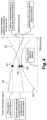
- the figure 4 describes the data needed to describe a reference situation for the operation of the pump. This reference situation will allow the behavior of the pump to be analyzed by following the movement of the service point relative to the reference service point, in the reference situation.
- Pump performance curves are established in particular from data provided by the pump manufacturer. A reference situation is determined, either from measured and calculated data, or from data provided by the manufacturer to characterize nominal operation of the pump.
- the first curve 40 represents a pump flow rate as a function of a total manometric head.
- a first initial service point 41 corresponds to a reference service point.
- the reference service point 41 is obtained by determining the pump flow rate as a function of the total manometric head in a reference configuration of the pumping station 1 and the system it serves.
- FIG 4 also represents a second performance curve 42 representing the mechanical power called by the pump on its impeller shaft as a function of the pump flow rate.
- a second reference service point 43 can be defined as a function of the reference mechanical power at the reference flow rate.
- a third performance curve 44 may be defined from the pump efficiency as a function of the pump flow rate.
- a third reference point 45 may be defined as the pump efficiency in the reference situation at the reference flow rate.
- the eighth step 38 is a step of comparing the current operating point of the pump with the corresponding performance curve of the pump and thus of identifying a possible drift of the operating point with respect to the performance curve of the pump and with respect to the first reference service point 41 previously defined.
- FIG 5 represents a division into zones of the two-dimensional space defined by the pump flow rate and the total head.
- the division into zones uses the first pump performance curve 40 as well as the first reference service point 41.
- the characteristic curve 50 of pumping station 1 is also shown.
- a first zone 51 is positioned below the first performance curve of the pump 40 and above a line at constant nanometric height equal to the nanometric height of the first reference service point 41.
- the first zone 51 is called a zone of increase in the HMT and decrease in the flow rate of the pump.
- a second zone 52 is defined for all operating points whose total manometric height is lower than the manometric height of the first reference service point 41 and therefore for a pump flow rate lower than the pump flow rate at the first reference point 41.
- the second zone 52 is called the HMT reduction and pump flow rate reduction zone.
- a third zone 53 is defined below the pump performance curve 40, for service points whose flow rate is greater than the pump flow rate at the first reference point 41.
- the third zone 53 is called the HMT decrease and flow rate increase zone.
- a fourth zone 54 is defined for all operating points above the characteristic curve of the pumping station.
- the fourth zone 54 is called the performance increase zone.
- a drift of the pump service point in the fourth zone 54 may mean that the diameter of the pump impeller has been modified and in particular increased, or that the rotation speed has increased or both.
- An action to be taken as a preventive measure may then be to update the characteristics of the pump in the database.
- the ninth step 39 is a step of creating a history of the different service points of the engine, determined during the operation of the pumping station 1.
- the evolution of the service point of the engine is evaluated from a reference situation as represented on the figure 6 .
- FIG. 6 illustrates a reference situation that can be used to analyze possible drifts in the service point of an engine 21.
- the abscissa axis represents the mechanical power of the engine.
- a first curve 61 represents the intensity of the electric current called.
- a second curve 62 represents the active electric power called.
- a reference service point is defined on each curve 61, 62 for a mechanical power 63 delivered by the motor in the reference situation. It is thus possible to determine an intensity called for the reference service point 64. Then, it is also possible to determine an active electric power 65 called for the reference service point, for the mechanical power delivered by the motor at the reference service point.
- the tenth step 300 is a step of analyzing a possible drift of the service point of the engine 21 and an interpretation of the drift if it is observed in order to detect a possible operating anomaly. The analysis is based on an interpretation of the engine load as represented on the figure 7 .
- FIG. 7 represents different load curves on the motor shaft depending on the rotation speed of the motor shaft.
- a maximum torque is defined which allows a maximum torque speed to be defined below which the machine risks stalling. Above this maximum torque speed, the motor 21 is in a stable usage zone. In this stable usage zone, or usable stable zone, three characteristic curves of different motor loads are defined.
- a first load curve describes the load in accidental operation of the motor, or accidental load.
- a second load curve describes the nominal load.
- a third load curve describes the load of the motor when the machine is operating at no load. The intersection of these load curves with a curve defining the evolution of the torque of the motor as a function of its speed 71, gives the speeds corresponding to each type of load, accidental, nominal or at no load.
- the impeller When the pump impeller rotates without propelling liquid, which can be the case with a clogged impeller or a deprimed pump, the impeller does not produce hydraulic power.
- the motor then drives a freewheel and does not need much electrical power.
- the motor torque drops below the torque at the nominal load.
- One possible interpretation is that there is an air inlet in the pump. The stopping of the motor and the pump can be automatically implemented by the electrical cabinet 3 of the pumping system 2.
- the pump wheel When the pump wheel turns but its rotation is slowed, for example: in the event of mechanical clearances clogged by debris, in the event of clogging by concretions, in the event of the start of seizure of the thrust bearing on a drilling pump, then the pump wheel produces the hydraulic power necessary to provide the service expected but the electric motor delivers on the one hand the mechanical power which is converted into hydraulic power and, on the other hand, an increase in mechanical power which makes it possible to counterbalance the braking undergone the wheel.
- the engine torque rises above the torque at the nominal load and goes into accidental load. In this case too, it is appropriate to couple the analysis of the called intensity, by defining a high threshold beyond which it is considered that the engine is operating in overload. Crossing the high threshold associated with an engine torque corresponding to an accidental load requires a curative shutdown of the pump and the engine. This shutdown can be implemented by the pumping system management device, comprising the electrical cabinet 3 and the supervision system 7.
- An increase in active electrical power concomitant with a decrease in HMT and a decrease in suction pressure means that the pump suction is clogging and the pump is cavitating.
- An increase in motor temperature indicates the imminent threat of overheating of the motor windings.
- the pump should be stopped immediately and a detailed inspection of the suction should be carried out. of the pump, that is to say of the strainer 25, of the pipes, of the water intake, etc.
- the analysis of the submergence calculated by taking into account in particular the thickness of the water slice in the water intake makes it possible to determine whether a swirling flow disturbs the velocity field at the pump inlet and whether it causes an air inlet in the pump which could cause the pump to lose its prime or at least cause the pump to vibrate.
- the water level must be raised above the water intake, for example by reducing the pump flow rate or by stopping the pump as a corrective measure.
- the analysis is also based on the temporal evolution of the discharge pressure in relation to the flow rate served by the pump.
- a first indicator is the service flow rate circulating in the discharge pipe. Indeed, a loss of flow rate results in a reduction in the diameter of the discharge pipe. Depending on the reduction in diameter that is determined, it may be necessary to carry out a cleaning action on the pipe as a corrective measure.
- Another indicator can be a ratio between the service flow rate of the pump and the flow rate at a point of best pump efficiency determined on the pump efficiency performance curve.
- the thirteenth step 304, 305 is a step of analysis of a possible drift of the characteristic curve of the suction 304, a step of interpretation of this drift then a pre-diagnosis 305 of a malfunction of the suction pipe on detection of an anomaly.
- the thirteenth step 304, 305 is optional for submersible pumps, that is to say those which are not connected to a water intake via a suction pipe.
- the fourteenth step 306 is a pre-diagnostic step of the probable causes of pump malfunctions.
- This step is a step allowing to link several indicators of hydraulic failures to possible hydraulic causes of these failures.
- the indicators considered for this pre-diagnostic step result from the analyses previously carried out. These indicators are the following operating conditions: no flow, insufficient flow, insufficient pressure, intermittent flow. Possible causes are for example "the pump is not not primed or losing prime” when all of the above operating conditions are met, or “too much air is trapped in the pumped liquid”, no flow alone may indicate a “clogged impeller”, insufficient flow alone may indicate incorrect direction of rotation of the pump impeller, etc.
- the bearings are hot or fail very regularly then the probable cause could be inadequate cooling of the lubricant or an axial or radial load in excess of the design loads of the engine bearings.
- a single failure such as "failures on the seals are very frequent” could be related to overheating of the seal friction faces or a lack of wash water on the seal friction faces or incorrect assembly of the seal, etc.
- the available NPSH depends on the suction circuit and the suction flow rate, while the NPSH required by the pump depends on the pump and the flow rate it delivers.
- the pump may be the site of the cavitation phenomenon likely to damage the pump: in fact, cavitation exposes the pump to erosion which can destroy the pump impeller and lead to the replacement of the pump, in particular by another type of pump better suited to the operating conditions. The appearance of this phenomenon may be a sign that the pump used is not suitable for the required service.
- a seventeenth step 308 is a step of controlling the energy performance of the pumping group.
- Wear and tear of the pumping system can also be detected by monitoring the specific energy consumption of the pumping system, particularly if there is a statistically significant upward difference.
- the device and the method according to the invention make it possible to detect anomalies in the operation of the pumping station and to implement preventive or curative actions in order to avoid or minimize the consequences of anomalies on the operation or integrity of the pumping system.
- the pumping system is maintained in operational condition, that is to say in a state of good functioning, in an efficient and inexpensive manner.
- the various embodiments of the present invention comprise various steps. These steps can be implemented by instructions of a machine executable by means of a microprocessor for example.
- these steps can be performed by specific integrated circuits that include hardwired logic to perform the steps, or by any combination of programmable components and custom components.
- the present invention may also be provided in the form of a computer program product which may comprise a non-transitory computer memory medium containing instructions executable on a computing machine, which instructions may be used to program a computer (or other electronic device) to perform the method.
Landscapes
- Engineering & Computer Science (AREA)
- Mechanical Engineering (AREA)
- General Engineering & Computer Science (AREA)
- Control Of Non-Positive-Displacement Pumps (AREA)
- Control Of Positive-Displacement Pumps (AREA)
Claims (7)
- Verfahren zum Aufrechterhalten eines Betriebszustands (30) eines Pumpsystems (2), das Teil einer Pumpstation (1) ist, das Pumpsystem (2) umfassend eine Pumpe (20), einen Motor (21), der die Pumpe (20) antreibt, eine Leitung zum Fördern von Fluid durch die Pumpe (20) undeine Leitung zum Ansaugen von Fluid durch die Pumpe (20), das Verfahren umfassend mindestens die folgenden Schritte:- Messen von physikalischen Größen, die für den Betrieb des Pumpsystems (2) charakteristisch sind, einschließlich physikalischer Größen, die für den Zustand der Förderleitung der Pumpe (20) und den Zustand der Saugleitung der Pumpe (20) charakteristisch sind;- Analysieren und Auslegen gemessener physikalischer Größen, um eine oder mehrere Anomalien zu erkennen;- Vordiagnostizieren der wahrscheinlichen Ursachen für die erkannten Anomalien und Bestimmen der präventiven und korrigierenden Maßnahmen, die an dem Pumpsystem (2) durchgeführt werden müssen;- automatisches Implementieren von präventiven und korrigierenden Maßnahmen an dem Pumpsystem (2),gekennzeichnet, dadurch, dass eseinen Analyse- und Auslegungsschritt von charakteristischen Betriebskurven der Saug- (304) und Förderleitung (302) der Pumpe (20) und einen Kontrollschritt eines Eintauchens (301) eines Wassereinlasses an dem Eingang des Pumpsystems (2) umfasst,wobei der Analyse- und Auslegungsschritt des Betriebs der Förderleitung (302) der Pumpe (2) die zeitliche Entwicklung der folgenden Parameter berücksichtigt, die gemessen oder berechnet werden:einen Förderdruck der Pumpe,eine Fördermenge, die von der Pumpe geleistet wird,eine Stromstärke, die von dem Motor aufgenommen wird,eine Wirkleistung, die von dem Motor aufgenommen wird,wobei der Analyseschritt auch auf der zeitlichen Entwicklung des Förderdrucks in Bezug auf die von der Pumpe geleistete Fördermenge basiert, was zur Erkennung eines Verstopfungsproblems in der Förderleitung führt, und wenn ein Verstopfungsproblem erkannt wird, wird eine Reinigungsaktion der Leitung als Abhilfemaßnahme durchgeführt.
- Verfahren nach dem vorherigen Anspruch, dadurch gekennzeichnet, dass es einen Analyse- und Auslegungsschritt der Entwicklung von Betriebspunkten (38) der Pumpe (20) und einen Analyse- und Auslegungsschritt der Entwicklung von Betriebspunkten des Motors (300) umfasst.
- Verfahren nach einem der vorherigen Ansprüche, dadurch gekennzeichnet, dass es einen Kontrollschritt der Energieeffizienz (309) des Pumpsystems (2) umfasst.
- Verfahren nach einem der vorherigen Ansprüche, dadurch gekennzeichnet, dass es einen Erkennungsschritt eines Kavitationsphänomens (308) umfasst.
- Verfahren nach einem der vorherigen Ansprüche, dadurch gekennzeichnet, dass der Kontrollschritt eines Eintauchens des Wassereinlasses (301) eine Wasserhöhe in dem Wassereinlass, eine von der Pumpe (20) an dem Wassereinlass angesaugte Durchflussmenge, Parameter zur physikalischen Beschreibung des Wassereinlasses berücksichtigt.
- Verfahren nach einem der vorherigen Ansprüche, dadurch gekennzeichnet, dass der Analyse- und Auslegungsschritt des Betriebs der Saugleitung (304), die zeitliche Entwicklung der folgenden Parameter berücksichtigt: einen Druck auf der Saugseite der Pumpe, einen von der Pumpe geförderten Volumenstrom, eine von dem Motor (21) aufgenommene Stromstärke, eine von dem Motor (21) aufgenommene Wirkleistung, eine Gesamtförderhöhe, einen verfügbaren NPSH.
- Vorrichtung zum Aufrechterhalten eines Betriebszustands eines Pumpsystems (2), das Teil einer Pumpstation (1) ist, das Pumpsystem (2) umfassend eine Pumpe (20), einen Motor (21), der die Pumpe (20) antreibt, und mindestens eine Förderleitung und eine Saugleitung des Fluid durch die Pumpe (20), wobei die Vorrichtung dadurch gekennzeichnet ist, dass sie Folgendes umfasst:- hydraulische und mechanische Sensoren, die Messungen von hydraulischen und mechanischen Größen an der Pumpe (20), der Förderleitung und der Saugleitung durchführen;- elektrische und mechanische Sensoren, die Messungen von elektrischen und mechanischen Größen an dem Motor (21) durchführen;- einen Schaltschrank (3) für das Pumpsystem (2), der die Messungen der hydraulischen, elektrischen und mechanischen Sensoren sammelt, der Betriebsanweisungen an das Pumpsystem (2) überträgt;- ein Überwachungssystem (7), umfassend einen Rechner, auf dem ein zentrales Programm (8) ausgeführt wird, das das Verfahren zum Aufrechterhalten des Betriebszustands eines Pumpsystems (2) nach einem der vorherigen Ansprüche implementiert, wobei das Überwachungssystem (7) geeignet ist, um abhängig von den Analyse-, Auslegungs- und Vordiagnoseresultaten, die auf einem Analyse- und Auslegungsschritt von Betriebskennkurven der Saugleitung (304) und der Förderleitung (302) der Pumpe (20) und einem Kontrollschritt eines Eintauchens (301) eines Wassereinlasses an dem Eingang des Pumpsystems (2) automatisch Befehle an den Schaltschrank (3) zu übertragen, das Überwachungssystem (7) umfassend eine Mensch-Maschine-Schnittstelle zur Anzeige der Resultate der Analyse, Auslegung und Vordiagnose.
Applications Claiming Priority (2)
| Application Number | Priority Date | Filing Date | Title |
|---|---|---|---|
| FR1760073A FR3072737B1 (fr) | 2017-10-25 | 2017-10-25 | Procede et dispositif de maintien en condition operationnelle d'un systeme de pompage |
| PCT/EP2018/079057 WO2019081524A1 (fr) | 2017-10-25 | 2018-10-23 | Procédé et dispositif de maintien en condition opérationnelle d'un système de pompage |
Publications (2)
| Publication Number | Publication Date |
|---|---|
| EP3701152A1 EP3701152A1 (de) | 2020-09-02 |
| EP3701152B1 true EP3701152B1 (de) | 2024-09-25 |
Family
ID=61132559
Family Applications (1)
| Application Number | Title | Priority Date | Filing Date |
|---|---|---|---|
| EP18789158.5A Active EP3701152B1 (de) | 2017-10-25 | 2018-10-23 | Verfahren und vorrichtung zur bewahrung eines pumpsystems im betriebszustand |
Country Status (8)
| Country | Link |
|---|---|
| US (1) | US11920600B2 (de) |
| EP (1) | EP3701152B1 (de) |
| CN (1) | CN111247344B (de) |
| AU (1) | AU2018356378B2 (de) |
| CL (1) | CL2020001085A1 (de) |
| FR (1) | FR3072737B1 (de) |
| MA (1) | MA50444A (de) |
| WO (1) | WO2019081524A1 (de) |
Families Citing this family (5)
| Publication number | Priority date | Publication date | Assignee | Title |
|---|---|---|---|---|
| EP3904682B1 (de) | 2020-04-27 | 2023-11-29 | Xylem Europe GmbH | Verfahren zur überwachung und steuerung des betriebs einer pumpstation |
| JP7577989B2 (ja) * | 2020-12-08 | 2024-11-06 | 富士電機株式会社 | ポンプの目詰まり検知システム |
| US12270962B1 (en) | 2023-03-22 | 2025-04-08 | Sevee & Maher Engineers, Inc. | Specific capacity measurement and estimation in a well, systems, apparatuses, and methods |
| US12392205B2 (en) * | 2024-01-10 | 2025-08-19 | Halliburton Energy Services, Inc. | Automatically detecting a key parameter affecting pump components |
| US12241354B1 (en) | 2024-01-10 | 2025-03-04 | Halliburton Energy Services, Inc. | Automatically determining flow type histories for frack pumps and managing usage thereof using the flow type histories |
Citations (8)
| Publication number | Priority date | Publication date | Assignee | Title |
|---|---|---|---|---|
| JPH02173372A (ja) | 1988-12-24 | 1990-07-04 | Kubota Ltd | ポンプ配管の詰まり及び破損の検出方法及び装置 |
| US4999117A (en) | 1988-06-08 | 1991-03-12 | Oy E. Sarlin Ab | Monitoring method for wastewater pump station and compatible apparatus |
| US6260004B1 (en) | 1997-12-31 | 2001-07-10 | Innovation Management Group, Inc. | Method and apparatus for diagnosing a pump system |
| JP2003028076A (ja) | 2001-07-12 | 2003-01-29 | Hitachi Ltd | ポンプ異常診断装置 |
| WO2006019352A1 (en) | 2004-08-19 | 2006-02-23 | Itt Manufacturing Enterprises Inc. | Method and device for operating a pump station |
| US20090204267A1 (en) * | 2001-08-10 | 2009-08-13 | Rockwell Automation Technologies, Inc. | System and method for dynamic multi-objective optimization of machine selection, integration and utilization |
| JP2015162036A (ja) | 2014-02-27 | 2015-09-07 | 新日鐵住金株式会社 | 電動ポンプの稼働状態を監視する監視装置、およびプログラム |
| GB2537461A (en) | 2015-02-16 | 2016-10-19 | Pulsar Process Measurement Ltd | Pump monitoring method |
Family Cites Families (17)
| Publication number | Priority date | Publication date | Assignee | Title |
|---|---|---|---|---|
| FR2082704A5 (de) * | 1970-03-24 | 1971-12-10 | Hayward Pierre | |
| US3844673A (en) * | 1970-03-24 | 1974-10-29 | P Hayward | Process for the regulation of the flow in conduits |
| US6033187A (en) * | 1997-10-17 | 2000-03-07 | Giw Industries, Inc. | Method for controlling slurry pump performance to increase system operational stability |
| EP1247986B1 (de) * | 2000-01-12 | 2008-10-08 | Ebara Corporation | Methode, um das kennfeld einer zentrifugiermaschine mit dem rechner zu erstellen |
| US6688320B2 (en) * | 2000-11-10 | 2004-02-10 | Flowtronex Psi, Inc. | Utility conservation control methodology within a fluid pumping system |
| US7797062B2 (en) * | 2001-08-10 | 2010-09-14 | Rockwell Automation Technologies, Inc. | System and method for dynamic multi-objective optimization of machine selection, integration and utilization |
| DE102006022740A1 (de) * | 2006-05-12 | 2007-11-15 | Ksb Aktiengesellschaft | Einrichtung zur Messwertübertragung |
| CA2765155C (en) * | 2009-06-12 | 2018-05-15 | Cidra Corporate Services Inc. | Method and apparatus for predicting maintenance needs of a pump based at least partly on pump performance analysis |
| GB0916887D0 (en) * | 2009-09-28 | 2009-11-11 | Wellmack Resources Ltd | Improved blockage apparatus and method |
| US9127678B2 (en) * | 2011-04-06 | 2015-09-08 | Field Intelligence, Inc. | Fast-response pump monitoring and in-situ pump data recording system |
| EP2606803B1 (de) * | 2011-12-20 | 2020-03-18 | Copreci, S.Coop. | Verfahren zur Steuerung für ein Wasch-Haushaltsgerät, und Wasch-Haushaltsgerät |
| JP2013217346A (ja) * | 2012-04-12 | 2013-10-24 | Hitachi Ltd | ポンプ吸込管 |
| US9886018B2 (en) * | 2014-09-12 | 2018-02-06 | Smith & Loveless Inc. | Pump control for operation on a variable pressure force main |
| SG10201405714SA (en) | 2014-09-15 | 2016-04-28 | Yokogawa Engineering Asia Pte Ltd | Method, system and computer program for fault detection in a machine |
| CN104866704A (zh) | 2015-03-21 | 2015-08-26 | 北京化工大学 | 一种基于模糊综合评判的离心泵状态评估方法 |
| CN206582134U (zh) | 2017-03-20 | 2017-10-24 | 湖北省安全生产应急救援中心 | 一种矿用主排水泵智能控制系统 |
| CN107013473A (zh) | 2017-04-19 | 2017-08-04 | 武汉惜源科技有限公司 | 一种泵站实时在线监测与能效管理方法及系统 |
-
2017
- 2017-10-25 FR FR1760073A patent/FR3072737B1/fr active Active
-
2018
- 2018-10-23 AU AU2018356378A patent/AU2018356378B2/en active Active
- 2018-10-23 US US16/759,005 patent/US11920600B2/en active Active
- 2018-10-23 MA MA050444A patent/MA50444A/fr unknown
- 2018-10-23 WO PCT/EP2018/079057 patent/WO2019081524A1/fr not_active Ceased
- 2018-10-23 CN CN201880068734.XA patent/CN111247344B/zh active Active
- 2018-10-23 EP EP18789158.5A patent/EP3701152B1/de active Active
-
2020
- 2020-04-22 CL CL2020001085A patent/CL2020001085A1/es unknown
Patent Citations (8)
| Publication number | Priority date | Publication date | Assignee | Title |
|---|---|---|---|---|
| US4999117A (en) | 1988-06-08 | 1991-03-12 | Oy E. Sarlin Ab | Monitoring method for wastewater pump station and compatible apparatus |
| JPH02173372A (ja) | 1988-12-24 | 1990-07-04 | Kubota Ltd | ポンプ配管の詰まり及び破損の検出方法及び装置 |
| US6260004B1 (en) | 1997-12-31 | 2001-07-10 | Innovation Management Group, Inc. | Method and apparatus for diagnosing a pump system |
| JP2003028076A (ja) | 2001-07-12 | 2003-01-29 | Hitachi Ltd | ポンプ異常診断装置 |
| US20090204267A1 (en) * | 2001-08-10 | 2009-08-13 | Rockwell Automation Technologies, Inc. | System and method for dynamic multi-objective optimization of machine selection, integration and utilization |
| WO2006019352A1 (en) | 2004-08-19 | 2006-02-23 | Itt Manufacturing Enterprises Inc. | Method and device for operating a pump station |
| JP2015162036A (ja) | 2014-02-27 | 2015-09-07 | 新日鐵住金株式会社 | 電動ポンプの稼働状態を監視する監視装置、およびプログラム |
| GB2537461A (en) | 2015-02-16 | 2016-10-19 | Pulsar Process Measurement Ltd | Pump monitoring method |
Also Published As
| Publication number | Publication date |
|---|---|
| CN111247344A (zh) | 2020-06-05 |
| CN111247344B (zh) | 2022-07-22 |
| WO2019081524A1 (fr) | 2019-05-02 |
| US20200340483A1 (en) | 2020-10-29 |
| MA50444A (fr) | 2020-09-02 |
| US11920600B2 (en) | 2024-03-05 |
| CL2020001085A1 (es) | 2020-08-14 |
| FR3072737A1 (fr) | 2019-04-26 |
| AU2018356378B2 (en) | 2025-01-23 |
| AU2018356378A1 (en) | 2020-06-04 |
| FR3072737B1 (fr) | 2021-09-24 |
| EP3701152A1 (de) | 2020-09-02 |
Similar Documents
| Publication | Publication Date | Title |
|---|---|---|
| EP3701152B1 (de) | Verfahren und vorrichtung zur bewahrung eines pumpsystems im betriebszustand | |
| US11341836B2 (en) | Persistent monitoring and real time low latency local control of centrifugal hydraulic pump, remote monitoring and control, and collecting data to produce performance profiles | |
| US20250003557A1 (en) | Supplemental filtration for machine fluid systems | |
| US12352258B2 (en) | Controlling fluid operations for machine systems | |
| US20150308304A1 (en) | Variable fluid flow techniques for machine fluid systems | |
| KR102208831B1 (ko) | 모터펌프의 진단 장치 및 방법 | |
| FR2979377B1 (fr) | Systeme et procede pour prevoir des frottements dans une turbine | |
| FR2923926A1 (fr) | Detection et signalements automatiques de la degradation d'une piece interne de turbine | |
| CN110083962B (zh) | 一种离心泵主轴运行寿命的预测方法及预测系统 | |
| FR3045737A1 (fr) | Procede de surveillance de performance de puits ou trou de forage et systeme | |
| CN104321529B (zh) | 用于监测并控制正排量泵中的汽蚀的系统和方法 | |
| CN117514734A (zh) | 检测装置、检测方法以及检测系统 | |
| JP2023094732A (ja) | ポンプの診断方法 | |
| BE1025462B1 (fr) | Détermination d'un colmatage d'un filtre d'un système hydraulique | |
| Mostafa et al. | Condition monitoring as a pathway for sustainable operation: a case study for vibration analysis on centrifugal pumps | |
| Hicks | Improving Jet Lift Runtime Using Machine Learning and Enhanced Power Fluid Pump Instrumentation | |
| JP7645766B2 (ja) | 管理方法および管理プログラム | |
| Davids | Vibration-based signal feature generation for centrifugal pump condition monitoring. | |
| CN120845380A (zh) | 一种水泵及其智慧高效运维方法 |
Legal Events
| Date | Code | Title | Description |
|---|---|---|---|
| STAA | Information on the status of an ep patent application or granted ep patent |
Free format text: STATUS: UNKNOWN |
|
| STAA | Information on the status of an ep patent application or granted ep patent |
Free format text: STATUS: THE INTERNATIONAL PUBLICATION HAS BEEN MADE |
|
| PUAI | Public reference made under article 153(3) epc to a published international application that has entered the european phase |
Free format text: ORIGINAL CODE: 0009012 |
|
| STAA | Information on the status of an ep patent application or granted ep patent |
Free format text: STATUS: REQUEST FOR EXAMINATION WAS MADE |
|
| 17P | Request for examination filed |
Effective date: 20200520 |
|
| AK | Designated contracting states |
Kind code of ref document: A1 Designated state(s): AL AT BE BG CH CY CZ DE DK EE ES FI FR GB GR HR HU IE IS IT LI LT LU LV MC MK MT NL NO PL PT RO RS SE SI SK SM TR |
|
| AX | Request for extension of the european patent |
Extension state: BA ME |
|
| DAX | Request for extension of the european patent (deleted) | ||
| RAV | Requested validation state of the european patent: fee paid |
Extension state: MA Effective date: 20200520 |
|
| STAA | Information on the status of an ep patent application or granted ep patent |
Free format text: STATUS: EXAMINATION IS IN PROGRESS |
|
| 17Q | First examination report despatched |
Effective date: 20221027 |
|
| RAP1 | Party data changed (applicant data changed or rights of an application transferred) |
Owner name: SUEZ INTERNATIONAL |
|
| P01 | Opt-out of the competence of the unified patent court (upc) registered |
Effective date: 20230601 |
|
| GRAP | Despatch of communication of intention to grant a patent |
Free format text: ORIGINAL CODE: EPIDOSNIGR1 |
|
| STAA | Information on the status of an ep patent application or granted ep patent |
Free format text: STATUS: GRANT OF PATENT IS INTENDED |
|
| INTG | Intention to grant announced |
Effective date: 20240517 |
|
| GRAS | Grant fee paid |
Free format text: ORIGINAL CODE: EPIDOSNIGR3 |
|
| GRAA | (expected) grant |
Free format text: ORIGINAL CODE: 0009210 |
|
| STAA | Information on the status of an ep patent application or granted ep patent |
Free format text: STATUS: THE PATENT HAS BEEN GRANTED |
|
| AK | Designated contracting states |
Kind code of ref document: B1 Designated state(s): AL AT BE BG CH CY CZ DE DK EE ES FI FR GB GR HR HU IE IS IT LI LT LU LV MC MK MT NL NO PL PT RO RS SE SI SK SM TR |
|
| REG | Reference to a national code |
Ref country code: GB Ref legal event code: FG4D Free format text: NOT ENGLISH |
|
| REG | Reference to a national code |
Ref country code: CH Ref legal event code: EP |
|
| REG | Reference to a national code |
Ref country code: DE Ref legal event code: R096 Ref document number: 602018074742 Country of ref document: DE |
|
| REG | Reference to a national code |
Ref country code: IE Ref legal event code: FG4D Free format text: LANGUAGE OF EP DOCUMENT: FRENCH |
|
| REG | Reference to a national code |
Ref country code: LT Ref legal event code: MG9D |
|
| PG25 | Lapsed in a contracting state [announced via postgrant information from national office to epo] |
Ref country code: NO Free format text: LAPSE BECAUSE OF FAILURE TO SUBMIT A TRANSLATION OF THE DESCRIPTION OR TO PAY THE FEE WITHIN THE PRESCRIBED TIME-LIMIT Effective date: 20241225 |
|
| PG25 | Lapsed in a contracting state [announced via postgrant information from national office to epo] |
Ref country code: GR Free format text: LAPSE BECAUSE OF FAILURE TO SUBMIT A TRANSLATION OF THE DESCRIPTION OR TO PAY THE FEE WITHIN THE PRESCRIBED TIME-LIMIT Effective date: 20241226 Ref country code: FI Free format text: LAPSE BECAUSE OF FAILURE TO SUBMIT A TRANSLATION OF THE DESCRIPTION OR TO PAY THE FEE WITHIN THE PRESCRIBED TIME-LIMIT Effective date: 20240925 |
|
| PG25 | Lapsed in a contracting state [announced via postgrant information from national office to epo] |
Ref country code: BG Free format text: LAPSE BECAUSE OF FAILURE TO SUBMIT A TRANSLATION OF THE DESCRIPTION OR TO PAY THE FEE WITHIN THE PRESCRIBED TIME-LIMIT Effective date: 20240925 |
|
| PG25 | Lapsed in a contracting state [announced via postgrant information from national office to epo] |
Ref country code: LV Free format text: LAPSE BECAUSE OF FAILURE TO SUBMIT A TRANSLATION OF THE DESCRIPTION OR TO PAY THE FEE WITHIN THE PRESCRIBED TIME-LIMIT Effective date: 20240925 |
|
| PG25 | Lapsed in a contracting state [announced via postgrant information from national office to epo] |
Ref country code: RS Free format text: LAPSE BECAUSE OF FAILURE TO SUBMIT A TRANSLATION OF THE DESCRIPTION OR TO PAY THE FEE WITHIN THE PRESCRIBED TIME-LIMIT Effective date: 20241225 |
|
| REG | Reference to a national code |
Ref country code: NL Ref legal event code: MP Effective date: 20240925 |
|
| PG25 | Lapsed in a contracting state [announced via postgrant information from national office to epo] |
Ref country code: RS Free format text: LAPSE BECAUSE OF FAILURE TO SUBMIT A TRANSLATION OF THE DESCRIPTION OR TO PAY THE FEE WITHIN THE PRESCRIBED TIME-LIMIT Effective date: 20241225 Ref country code: NO Free format text: LAPSE BECAUSE OF FAILURE TO SUBMIT A TRANSLATION OF THE DESCRIPTION OR TO PAY THE FEE WITHIN THE PRESCRIBED TIME-LIMIT Effective date: 20241225 Ref country code: LV Free format text: LAPSE BECAUSE OF FAILURE TO SUBMIT A TRANSLATION OF THE DESCRIPTION OR TO PAY THE FEE WITHIN THE PRESCRIBED TIME-LIMIT Effective date: 20240925 Ref country code: GR Free format text: LAPSE BECAUSE OF FAILURE TO SUBMIT A TRANSLATION OF THE DESCRIPTION OR TO PAY THE FEE WITHIN THE PRESCRIBED TIME-LIMIT Effective date: 20241226 Ref country code: FI Free format text: LAPSE BECAUSE OF FAILURE TO SUBMIT A TRANSLATION OF THE DESCRIPTION OR TO PAY THE FEE WITHIN THE PRESCRIBED TIME-LIMIT Effective date: 20240925 Ref country code: BG Free format text: LAPSE BECAUSE OF FAILURE TO SUBMIT A TRANSLATION OF THE DESCRIPTION OR TO PAY THE FEE WITHIN THE PRESCRIBED TIME-LIMIT Effective date: 20240925 |
|
| REG | Reference to a national code |
Ref country code: AT Ref legal event code: MK05 Ref document number: 1726834 Country of ref document: AT Kind code of ref document: T Effective date: 20240925 |
|
| PG25 | Lapsed in a contracting state [announced via postgrant information from national office to epo] |
Ref country code: NL Free format text: LAPSE BECAUSE OF FAILURE TO SUBMIT A TRANSLATION OF THE DESCRIPTION OR TO PAY THE FEE WITHIN THE PRESCRIBED TIME-LIMIT Effective date: 20240925 |
|
| PG25 | Lapsed in a contracting state [announced via postgrant information from national office to epo] |
Ref country code: IS Free format text: LAPSE BECAUSE OF FAILURE TO SUBMIT A TRANSLATION OF THE DESCRIPTION OR TO PAY THE FEE WITHIN THE PRESCRIBED TIME-LIMIT Effective date: 20250125 Ref country code: PT Free format text: LAPSE BECAUSE OF FAILURE TO SUBMIT A TRANSLATION OF THE DESCRIPTION OR TO PAY THE FEE WITHIN THE PRESCRIBED TIME-LIMIT Effective date: 20250127 |
|
| PG25 | Lapsed in a contracting state [announced via postgrant information from national office to epo] |
Ref country code: RO Free format text: LAPSE BECAUSE OF FAILURE TO SUBMIT A TRANSLATION OF THE DESCRIPTION OR TO PAY THE FEE WITHIN THE PRESCRIBED TIME-LIMIT Effective date: 20240925 Ref country code: SM Free format text: LAPSE BECAUSE OF FAILURE TO SUBMIT A TRANSLATION OF THE DESCRIPTION OR TO PAY THE FEE WITHIN THE PRESCRIBED TIME-LIMIT Effective date: 20240925 |
|
| PG25 | Lapsed in a contracting state [announced via postgrant information from national office to epo] |
Ref country code: ES Free format text: LAPSE BECAUSE OF FAILURE TO SUBMIT A TRANSLATION OF THE DESCRIPTION OR TO PAY THE FEE WITHIN THE PRESCRIBED TIME-LIMIT Effective date: 20240925 |
|
| PG25 | Lapsed in a contracting state [announced via postgrant information from national office to epo] |
Ref country code: AT Free format text: LAPSE BECAUSE OF FAILURE TO SUBMIT A TRANSLATION OF THE DESCRIPTION OR TO PAY THE FEE WITHIN THE PRESCRIBED TIME-LIMIT Effective date: 20240925 Ref country code: EE Free format text: LAPSE BECAUSE OF FAILURE TO SUBMIT A TRANSLATION OF THE DESCRIPTION OR TO PAY THE FEE WITHIN THE PRESCRIBED TIME-LIMIT Effective date: 20240925 |
|
| PG25 | Lapsed in a contracting state [announced via postgrant information from national office to epo] |
Ref country code: CZ Free format text: LAPSE BECAUSE OF FAILURE TO SUBMIT A TRANSLATION OF THE DESCRIPTION OR TO PAY THE FEE WITHIN THE PRESCRIBED TIME-LIMIT Effective date: 20240925 Ref country code: PL Free format text: LAPSE BECAUSE OF FAILURE TO SUBMIT A TRANSLATION OF THE DESCRIPTION OR TO PAY THE FEE WITHIN THE PRESCRIBED TIME-LIMIT Effective date: 20240925 |
|
| PG25 | Lapsed in a contracting state [announced via postgrant information from national office to epo] |
Ref country code: SK Free format text: LAPSE BECAUSE OF FAILURE TO SUBMIT A TRANSLATION OF THE DESCRIPTION OR TO PAY THE FEE WITHIN THE PRESCRIBED TIME-LIMIT Effective date: 20240925 |
|
| REG | Reference to a national code |
Ref country code: DE Ref legal event code: R119 Ref document number: 602018074742 Country of ref document: DE |
|
| REG | Reference to a national code |
Ref country code: CH Ref legal event code: PL |
|
| PLBI | Opposition filed |
Free format text: ORIGINAL CODE: 0009260 |
|
| PG25 | Lapsed in a contracting state [announced via postgrant information from national office to epo] |
Ref country code: MC Free format text: LAPSE BECAUSE OF FAILURE TO SUBMIT A TRANSLATION OF THE DESCRIPTION OR TO PAY THE FEE WITHIN THE PRESCRIBED TIME-LIMIT Effective date: 20240925 |
|
| PLAX | Notice of opposition and request to file observation + time limit sent |
Free format text: ORIGINAL CODE: EPIDOSNOBS2 |
|
| PG25 | Lapsed in a contracting state [announced via postgrant information from national office to epo] |
Ref country code: DE Free format text: LAPSE BECAUSE OF NON-PAYMENT OF DUE FEES Effective date: 20250501 |
|
| PG25 | Lapsed in a contracting state [announced via postgrant information from national office to epo] |
Ref country code: DK Free format text: LAPSE BECAUSE OF FAILURE TO SUBMIT A TRANSLATION OF THE DESCRIPTION OR TO PAY THE FEE WITHIN THE PRESCRIBED TIME-LIMIT Effective date: 20240925 |
|
| PG25 | Lapsed in a contracting state [announced via postgrant information from national office to epo] |
Ref country code: LU Free format text: LAPSE BECAUSE OF NON-PAYMENT OF DUE FEES Effective date: 20241023 Ref country code: BE Free format text: LAPSE BECAUSE OF NON-PAYMENT OF DUE FEES Effective date: 20241031 |
|
| PG25 | Lapsed in a contracting state [announced via postgrant information from national office to epo] |
Ref country code: CH Free format text: LAPSE BECAUSE OF NON-PAYMENT OF DUE FEES Effective date: 20241031 |
|
| 26 | Opposition filed |
Opponent name: KSB SE & CO. KGAA Effective date: 20250625 |
|
| REG | Reference to a national code |
Ref country code: BE Ref legal event code: MM Effective date: 20241031 |
|
| PG25 | Lapsed in a contracting state [announced via postgrant information from national office to epo] |
Ref country code: SE Free format text: LAPSE BECAUSE OF FAILURE TO SUBMIT A TRANSLATION OF THE DESCRIPTION OR TO PAY THE FEE WITHIN THE PRESCRIBED TIME-LIMIT Effective date: 20240925 |
|
| PG25 | Lapsed in a contracting state [announced via postgrant information from national office to epo] |
Ref country code: IE Free format text: LAPSE BECAUSE OF NON-PAYMENT OF DUE FEES Effective date: 20241023 |
|
| PLAB | Opposition data, opponent's data or that of the opponent's representative modified |
Free format text: ORIGINAL CODE: 0009299OPPO |
|
| PLBB | Reply of patent proprietor to notice(s) of opposition received |
Free format text: ORIGINAL CODE: EPIDOSNOBS3 |
|
| R26 | Opposition filed (corrected) |
Opponent name: KSB SE & CO. KGAA Effective date: 20250625 |
|
| PGFP | Annual fee paid to national office [announced via postgrant information from national office to epo] |
Ref country code: GB Payment date: 20251027 Year of fee payment: 8 |
|
| PGFP | Annual fee paid to national office [announced via postgrant information from national office to epo] |
Ref country code: IT Payment date: 20251021 Year of fee payment: 8 |
|
| PG25 | Lapsed in a contracting state [announced via postgrant information from national office to epo] |
Ref country code: HR Free format text: LAPSE BECAUSE OF FAILURE TO SUBMIT A TRANSLATION OF THE DESCRIPTION OR TO PAY THE FEE WITHIN THE PRESCRIBED TIME-LIMIT Effective date: 20240925 |
|
| PGFP | Annual fee paid to national office [announced via postgrant information from national office to epo] |
Ref country code: FR Payment date: 20251027 Year of fee payment: 8 |
|
| PG25 | Lapsed in a contracting state [announced via postgrant information from national office to epo] |
Ref country code: CY Free format text: LAPSE BECAUSE OF FAILURE TO SUBMIT A TRANSLATION OF THE DESCRIPTION OR TO PAY THE FEE WITHIN THE PRESCRIBED TIME-LIMIT; INVALID AB INITIO Effective date: 20181023 |