EP3700402B1 - Robot cleaner - Google Patents
Robot cleaner Download PDFInfo
- Publication number
- EP3700402B1 EP3700402B1 EP18887173.5A EP18887173A EP3700402B1 EP 3700402 B1 EP3700402 B1 EP 3700402B1 EP 18887173 A EP18887173 A EP 18887173A EP 3700402 B1 EP3700402 B1 EP 3700402B1
- Authority
- EP
- European Patent Office
- Prior art keywords
- robot cleaner
- main body
- dust
- suction passage
- suction
- Prior art date
- Legal status (The legal status is an assumption and is not a legal conclusion. Google has not performed a legal analysis and makes no representation as to the accuracy of the status listed.)
- Active
Links
Images




Classifications
-
- A—HUMAN NECESSITIES
- A47—FURNITURE; DOMESTIC ARTICLES OR APPLIANCES; COFFEE MILLS; SPICE MILLS; SUCTION CLEANERS IN GENERAL
- A47L—DOMESTIC WASHING OR CLEANING; SUCTION CLEANERS IN GENERAL
- A47L9/00—Details or accessories of suction cleaners, e.g. mechanical means for controlling the suction or for effecting pulsating action; Storing devices specially adapted to suction cleaners or parts thereof; Carrying-vehicles specially adapted for suction cleaners
- A47L9/02—Nozzles
- A47L9/06—Nozzles with fixed, e.g. adjustably fixed brushes or the like
- A47L9/068—Nozzles combined with a different cleaning side, e.g. duplex nozzles or dual purpose nozzles
-
- A—HUMAN NECESSITIES
- A47—FURNITURE; DOMESTIC ARTICLES OR APPLIANCES; COFFEE MILLS; SPICE MILLS; SUCTION CLEANERS IN GENERAL
- A47L—DOMESTIC WASHING OR CLEANING; SUCTION CLEANERS IN GENERAL
- A47L7/00—Suction cleaners adapted for additional purposes; Tables with suction openings for cleaning purposes; Containers for cleaning articles by suction; Suction cleaners adapted to cleaning of brushes; Suction cleaners adapted to taking-up liquids
- A47L7/04—Suction cleaners adapted for additional purposes; Tables with suction openings for cleaning purposes; Containers for cleaning articles by suction; Suction cleaners adapted to cleaning of brushes; Suction cleaners adapted to taking-up liquids for using the exhaust air for other purposes, e.g. for distribution of chemicals in a room, for sterilisation of the air
-
- A—HUMAN NECESSITIES
- A47—FURNITURE; DOMESTIC ARTICLES OR APPLIANCES; COFFEE MILLS; SPICE MILLS; SUCTION CLEANERS IN GENERAL
- A47L—DOMESTIC WASHING OR CLEANING; SUCTION CLEANERS IN GENERAL
- A47L13/00—Implements for cleaning floors, carpets, furniture, walls, or wall coverings
- A47L13/10—Scrubbing; Scouring; Cleaning; Polishing
- A47L13/40—Cleaning implements actuated by electrostatic attraction; Devices for cleaning same; Magnetic cleaning implements
-
- A—HUMAN NECESSITIES
- A47—FURNITURE; DOMESTIC ARTICLES OR APPLIANCES; COFFEE MILLS; SPICE MILLS; SUCTION CLEANERS IN GENERAL
- A47L—DOMESTIC WASHING OR CLEANING; SUCTION CLEANERS IN GENERAL
- A47L5/00—Structural features of suction cleaners
- A47L5/12—Structural features of suction cleaners with power-driven air-pumps or air-compressors, e.g. driven by motor vehicle engine vacuum
- A47L5/14—Structural features of suction cleaners with power-driven air-pumps or air-compressors, e.g. driven by motor vehicle engine vacuum cleaning by blowing-off, also combined with suction cleaning
-
- A—HUMAN NECESSITIES
- A47—FURNITURE; DOMESTIC ARTICLES OR APPLIANCES; COFFEE MILLS; SPICE MILLS; SUCTION CLEANERS IN GENERAL
- A47L—DOMESTIC WASHING OR CLEANING; SUCTION CLEANERS IN GENERAL
- A47L5/00—Structural features of suction cleaners
- A47L5/12—Structural features of suction cleaners with power-driven air-pumps or air-compressors, e.g. driven by motor vehicle engine vacuum
- A47L5/22—Structural features of suction cleaners with power-driven air-pumps or air-compressors, e.g. driven by motor vehicle engine vacuum with rotary fans
-
- A—HUMAN NECESSITIES
- A47—FURNITURE; DOMESTIC ARTICLES OR APPLIANCES; COFFEE MILLS; SPICE MILLS; SUCTION CLEANERS IN GENERAL
- A47L—DOMESTIC WASHING OR CLEANING; SUCTION CLEANERS IN GENERAL
- A47L9/00—Details or accessories of suction cleaners, e.g. mechanical means for controlling the suction or for effecting pulsating action; Storing devices specially adapted to suction cleaners or parts thereof; Carrying-vehicles specially adapted for suction cleaners
-
- A—HUMAN NECESSITIES
- A47—FURNITURE; DOMESTIC ARTICLES OR APPLIANCES; COFFEE MILLS; SPICE MILLS; SUCTION CLEANERS IN GENERAL
- A47L—DOMESTIC WASHING OR CLEANING; SUCTION CLEANERS IN GENERAL
- A47L9/00—Details or accessories of suction cleaners, e.g. mechanical means for controlling the suction or for effecting pulsating action; Storing devices specially adapted to suction cleaners or parts thereof; Carrying-vehicles specially adapted for suction cleaners
- A47L9/0009—Storing devices ; Supports, stands or holders
- A47L9/0018—Storing devices ; Supports, stands or holders integrated in or removably mounted upon the suction cleaner for storing parts of said suction cleaner
- A47L9/0027—Storing devices ; Supports, stands or holders integrated in or removably mounted upon the suction cleaner for storing parts of said suction cleaner specially adapted for holding the suction cleaning tools
-
- A—HUMAN NECESSITIES
- A47—FURNITURE; DOMESTIC ARTICLES OR APPLIANCES; COFFEE MILLS; SPICE MILLS; SUCTION CLEANERS IN GENERAL
- A47L—DOMESTIC WASHING OR CLEANING; SUCTION CLEANERS IN GENERAL
- A47L9/00—Details or accessories of suction cleaners, e.g. mechanical means for controlling the suction or for effecting pulsating action; Storing devices specially adapted to suction cleaners or parts thereof; Carrying-vehicles specially adapted for suction cleaners
- A47L9/02—Nozzles
-
- A—HUMAN NECESSITIES
- A47—FURNITURE; DOMESTIC ARTICLES OR APPLIANCES; COFFEE MILLS; SPICE MILLS; SUCTION CLEANERS IN GENERAL
- A47L—DOMESTIC WASHING OR CLEANING; SUCTION CLEANERS IN GENERAL
- A47L9/00—Details or accessories of suction cleaners, e.g. mechanical means for controlling the suction or for effecting pulsating action; Storing devices specially adapted to suction cleaners or parts thereof; Carrying-vehicles specially adapted for suction cleaners
- A47L9/02—Nozzles
- A47L9/04—Nozzles with driven brushes or agitators
- A47L9/0461—Dust-loosening tools, e.g. agitators, brushes
- A47L9/0466—Rotating tools
-
- A—HUMAN NECESSITIES
- A47—FURNITURE; DOMESTIC ARTICLES OR APPLIANCES; COFFEE MILLS; SPICE MILLS; SUCTION CLEANERS IN GENERAL
- A47L—DOMESTIC WASHING OR CLEANING; SUCTION CLEANERS IN GENERAL
- A47L9/00—Details or accessories of suction cleaners, e.g. mechanical means for controlling the suction or for effecting pulsating action; Storing devices specially adapted to suction cleaners or parts thereof; Carrying-vehicles specially adapted for suction cleaners
- A47L9/10—Filters; Dust separators; Dust removal; Automatic exchange of filters
- A47L9/16—Arrangement or disposition of cyclones or other devices with centrifugal action
- A47L9/1608—Cyclonic chamber constructions
-
- A—HUMAN NECESSITIES
- A47—FURNITURE; DOMESTIC ARTICLES OR APPLIANCES; COFFEE MILLS; SPICE MILLS; SUCTION CLEANERS IN GENERAL
- A47L—DOMESTIC WASHING OR CLEANING; SUCTION CLEANERS IN GENERAL
- A47L2201/00—Robotic cleaning machines, i.e. with automatic control of the travelling movement or the cleaning operation
Definitions
- the disclosure relates to a robot cleaner capable of efficiently cleaning not only a lower side of the robot cleaner but also a lateral side and an upper side of the robot cleaner.
- a robot cleaner is a home appliance that self-runs without user's operation and cleans any area.
- the robot cleaner includes a driving unit including wheels, a sensor for sensing the surrounding environment, a fan for generating a suction force, and a dust collecting apparatus for removing dust from the air sucked into a main body.
- the robot cleaner travels along a floor surface and it sucks air on the floor surface to perform cleaning.
- a suction port of the robot cleaner is formed on the bottom surface of the main body, and the suction port is provided with a rotating brush.
- the brush rotates to scatter dust, trash and the like accumulated on a floor surface while rotating the brush. The scattered dust, trash and the like are sucked into the main body by the suction force of the fan.
- US2007/113373 relates to a vacuum cleaner provided with a left cover and a right cover, which cover a suction port body, so as to be movable in the right and left direction to facilitate cleaning by expanding the suction port body when cleaning along the side of a wall or a corner of a room.
- KR20060067780 relates to a vacuum cleaner with an air blow function for collecting floor dust.
- an aspect of the invention is to provide a robot cleaner capable of enlarging a cleaning area to side walls or corners of a facility.
- Another aspect of the invention is to provide a robot cleaner having a simple structure with improved cleaning efficiency at the time of cleaning a side wall or a corner of a facility.
- Another aspect of the invention is to provide a robot cleaner provided with a cleaning tool capable of manual operation to clean pet hair or the like or efficiently clean furniture and the like.
- the side surface of the main body may include a left surface and a right surface, the side suction port may be formed on at least one of the left surface or the right surface, and the side discharge port may be formed on the side surface on which the side suction port is formed.
- the side suction port and the side discharge port are arranged to face each other.
- the robot cleaner may further include a bottom suction port formed on a bottom surface of the main body to suck dust below the main body, a main suction passage to guide the air sucked through the bottom suction port to the dust collecting apparatus, and an auxiliary suction passage to guide the air sucked through the side suction port to the dust collecting apparatus.
- the main suction passage and the auxiliary suction passage may join together in front of the dust collecting apparatus.
- the robot cleaner may further include a switching valve provided at a point where the main suction passage and the auxiliary suction passage join together such that the suction force of the fan is transmitted to either the main suction passage or the auxiliary suction passage.
- the switching valve may include a cylindrical valve housing and a valve body rotatably provided in the cylindrical valve housing.
- the valve body may be configured to be rotatable between a first position to open the main suction passage and close the auxiliary suction passage, and a second position to close the main suction passage and open the auxiliary suction passage.
- the valve body may include a valve passage connected to one of the main suction passage and the auxiliary suction passage, and the valve passage may be connected to the main suction passage when the valve body is in the first position and the valve passage is connected to the auxiliary suction passage when the valve body is in the second position.
- the dust collecting apparatus may include an inlet through which the air sucked through the main suction passage or the auxiliary suction passage flows, a cyclone chamber to centrifugally separate the dust by turning the air introduced through the inlet, a dust collecting chamber to collect the dust that has been removed from the cyclone chamber, and an outlet to discharge the dust-removed air from the cyclone chamber.
- the robot cleaner may further include an electrostatic adsorption plate provided on the side surface of the main body to adsorb dust from the outside of the main body through static electricity.
- the electrostatic adsorption plate may be disposed between the side suction port and the side discharge port.
- a robot cleaner includes a main body, a fan provided inside the main body and configured to generate a suction force, a dust collecting apparatus provided to remove dust from the air sucked into the main body, and an electrostatic adsorption plate provided on at least one of a top surface or a side surface of the main body to adsorb dust outside the main body through static electricity.
- the electrostatic adsorption plate may be provided on the side surface of the main body, and the robot cleaner may further include a side suction port formed on the side surface of the main body to suck dust adhering to the electrostatic adsorption plate.
- the electrostatic adsorption plate may be provided on the top surface of the main body, and the robot cleaner may further include a top suction port formed on the top surface of the main body to suck dust adhering to the electrostatic adsorption plate.
- a robot cleaner in accordance with another exemplary aspect of the disclosure, includes a main body, a fan provided inside the main body and configured to generate a suction force, a dust collecting apparatus provided to remove dust from the air sucked into the main body, a suction port formed on a bottom surface of the main body to suck dust below the main body, a main suction passage to guide the air sucked through the suction port to the dust collecting apparatus, a cleaning tool for hand-held and manual cleaning, a tool mounting part provided on the main body to detachably mount the cleaning tool, and an auxiliary suction passage to suck dust from the tool mounting part to remove dust attached to the cleaning tool mounted on the tool mounting part and guide the dust to the dust collecting apparatus.
- the tool mounting part may include a scraper configured to scrape dust adhering to the cleaning tool when the cleaning tool is mounted on the tool mounting part.
- the scraper may be configured to move in a process of mounting the cleaning tool, and the tool mounting part may include an elastic member to elastically support the scraper.
- the main suction passage and the auxiliary suction passage may join together in front of the dust collecting apparatus.
- the robot cleaner may further include a switching valve provided at a position where the main suction passage and the auxiliary suction passage join together such that the suction force of the fan is transmitted to either the main suction passage or the auxiliary suction passage.
- the robot cleaner can efficiently clean dust, garbage, pet hair, and the like in the vicinity of side walls or corners of a facility.
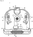
- FIG. 1 is a perspective view showing a robot cleaner according to an embodiment of the invention
- FIG. 2 is a bottom perspective view of the robot cleaner of FIG. 1 according to an embodiment of the invention
- FIG. 3 is a plan view of the robot cleaner of FIG. 1 according to an embodiment of the invention
- FIG. 4 is a side cross sectional view of the robot cleaner of FIG. 1 according to an embodiment of the invention
- FIG. 5 is a plan sectional view of the robot cleaner of FIG. 1 according to an embodiment of the invention
- FIG. 6 is a view showing a state in which a valve body of the robot cleaner of FIG. 1 is in a first position according to an embodiment of the invention
- FIG. 7 is a view showing a state in which the valve body of the robot cleaner of FIG. 1 is in a second position according to an embodiment of the invention
- a robot cleaner 1 includes a main body 10, a fan 20 provided inside the main body 10 to generate a suction force, and a dust collecting apparatus 30 provided to remove foreign matter such as dust from the air sucked into the main body 10.
- the main body 10 forms an outer appearance of the robot cleaner 1 and includes a top surface 11, a bottom surface 12, a front surface 13, a rear surface 14, a left surface 15, and a right surface 16.
- the front surface 13, the rear surface 14, the left surface 15 and the right surface 16 connect the top surface 11 and the bottom surface 12.
- the front surface 13, the rear surface 14, the left surface 15, and the right surface 16 may be formed as planes or curved surfaces, respectively.
- the front surface 13 is substantially linear when viewed from above the robot cleaner 1, and the rear surface 14, the left surface 15, and the right surface 16 are formed in a substantially curved shape.
- the front surface 13, the rear surface 14, the left surface 15, and the right surface 16 are all formed in an arc shape, and the robot cleaner 1 may be formed to have a circular shape as a whole when viewed from above.
- a sensor unit 2 may be provided on the top surface 11 of the main body 10 to sense the surrounding environment for autonomously running the robot cleaner 1 or to receive signals from a remote controller (not shown).
- a wheel 3 to run the robot cleaner 1 and a caster 5 to assist the wheels 3 and allow the main body 10 to travel stably can be provided on the bottom surface 12 of the main body 10.
- a pair of the wheels 3 is provided on the rear portion of the bottom surface 12 of the main body, and the caster 5 may be provided in front of the wheel 3.
- a wheel drive unit 4 for driving the wheel 3 may be provided inside the main body 10.
- the wheel drive unit 4 may include a drive motor for generating a rotational force, a gear assembly for transmitting the rotational force of the motor to the wheel 3, and the like.
- a bottom suction port 50 is formed in the bottom surface 12 of the main body 10 so as to suck the dust of an indoor or outdoor floor G into the main body 10, and the bottom suction port 50 may be provided with a brush 6 to scatter dust adhering to the floor G so as to be sucked smoothly.
- the brush 6 is rotatably provided and the main body 10 may be provided with a brush drive motor 7 to drive the brush 6.
- the dust collecting apparatus 30 may be provided at the center of the main body 10.
- the dust collecting apparatus 30 can be mounted on the main body 10 so as to be detachable upward.
- the dust collecting apparatus 30 is a cyclone type in which dust is separated using a centrifugal force.
- the invention is not limited thereto, and the dust collecting apparatus 30 using a dust bag or a filter may be employed.
- the dust collecting apparatus 30 includes an outer wall 31, a cyclone chamber 36 to form a swirling airflow to separate dust by the centrifugal force, a dust collecting chamber 37 to collect the dust separated through the cyclone chamber 36, an inner wall 32 to partition the cyclone chamber 36 and the dust collecting chamber 37, an opening 33 formed in the inner wall 32 so that the dust of the cyclone chamber 36 moves to the dust collecting chamber 37, an inlet 34 through which the air outside the dust collecting apparatus 30 flows into the dust collecting apparatus 30, and an outlet 35 through which air with the dust removed through the cyclone chamber 36 flows out of the dust collecting apparatus 30.
- a guide wall 38 is formed inside of the cyclone chamber 36 so as to guide the swirling airflow.
- a spiral wall 39 formed to be inclined in a helical shape may be provided around the guide wall 38 so as to form a swirl flow.
- the inner space of the guide wall 38 communicates with the outlet 35 and the upper portion of the guide wall 38 is provided with a grill 40 formed to prevent foreign matter such as dust from flowing to the outlet 35 and to guide air to flow to the outlet 35.
- the air outside the dust collecting apparatus 30 flows into the cyclone chamber 36 through the inlet 34 and is circulated around the guide wall 38 along the spiral wall 39 in the cyclone chamber 36.
- the dust is separated from the air by the centrifugal force, and the separated dust is collected through the opening 33 into the dust collecting chamber 37.
- the dust-removed air may pass through the grill 40 over the guide wall 38 and be discharged to the outside of the dust collecting apparatus 30 through the outlet 35.
- the user can remove the dust collecting apparatus 30 from the main body 10, remove the dust collected in the dust collecting chamber 37, and mount the dust collecting apparatus 30 in the main body 10 again.
- the fan 20 is connected to a motor 21 and can generate a suction force.
- the fan 20 and the motor 21 may be disposed in a fan motor chamber 22 at the rear of the main body 10.
- the fan motor chamber 22 can be connected to the outlet 35 of the dust collecting apparatus 30.
- the robot cleaner 1 may include side suction ports 51 and 52 formed in the side surfaces 15 and 16 of the main body 10 so as to suck dust beside the main body 10 into the main body 10.
- the side suction ports 51 and 52 may be formed on both the left surface 15 and the right surface 16 of the main body. But the invention is not limited thereto and the side suction ports 51 and 52 may be formed on only one of the left surface 15 and the right surface 16 of the main body.
- the robot cleaner 1 may include a top suction port 53 formed on the top surface 11 of the main body 10 so as to suck dust above the main body 10 into the main body 10.
- the robot cleaner 1 includes the bottom suction port 50 formed on the bottom surface 12 of the main body, the side suction ports 51 and 52 formed on the side surfaces 15 and 16 of the main body, and the top suction port 53 formed on the top surface 11 of the main body.
- the robot cleaner 1 includes a main suction passage 60 to transmit the suction force of the fan 20 to the bottom suction port 50 to suck air through the bottom suction port 50, and an auxiliary suction passage 61 to transmit the suction force of the fan 20 to the side suction ports 51 and 52 and the top suction port 53 to suck air through the side suction ports 51 and 52 and the top suction port 53.
- the main suction passage 60 connects the bottom suction port 50 to the inlet 34 of the dust collecting apparatus, and the auxiliary suction passage 61 can connect the side suction ports 51 and 52 and the inlet 34 of the dust collecting apparatus.
- the main suction passage 60 and the auxiliary suction passage 61 may be arranged to join together in front of the dust collecting apparatus 30. That is, the main suction passage 60 and the auxiliary suction passage 61 can be joined to the inlet 34 of the dust collecting apparatus 30 by one passage.
- a switching valve 62 may be provided to select whether to transmit the suction force of the fan 20 to the main suction passage 60 or to the auxiliary suction passage 61 at a point where the main suction passage 60 and the auxiliary suction passage 61 join.
- the switching valve 62 includes a cylindrical valve housing 63, a valve body 64 rotatably provided in the cylindrical valve housing 63, and a valve motor 66 to drive the valve body 64.
- the valve body 64 may be configured to be rotatable between a first position ( FIG. 6 ) in which the main suction passage 60 is opened and the auxiliary suction passage 61 is closed and a second position ( FIG. 7 ) in which the main suction passage 60 is closed and the auxiliary suction passage 61 is opened.
- the valve body 64 may include a valve passage 65 formed therein to be connected to either the main suction passage 60 or the auxiliary suction passage 61, depending on the position of the valve body 64.
- the valve passage 65 is connected to the main suction passage 60 when the valve body 64 is in the first position and is connected to the auxiliary suction passage 61 when the valve body 64 is in the second position.
- the robot cleaner 1 can have a first cleaning mode in which the valve body 64 is in the first position and a second cleaning mode in which the valve body 64 is in the second position.
- the first cleaning mode the main suction passage 60 is opened and the auxiliary suction passage 61 is closed so that the air on the floor can be cleaned through the bottom suction port 50.
- the second cleaning mode the main suction passage 60 is closed and the auxiliary suction passage 61 is opened so that the air in the lateral side and upper side of the main body can be sucked and cleaned through the side suction ports 51 and 52 and the top suction port 53.
- the robot cleaner 1 of the invention has a structure in which the main suction passage 60 and the auxiliary suction passage 61 can receive the suction force from the fan 20.
- the main suction passage 60 and the auxiliary suction passage 61 can receive the suction force from the fan 20.
- the main suction passage 60 and the auxiliary suction passage 61 are joined to each other to select one of the main suction passage 60 and the auxiliary suction passage 61 through the switching valve 62. Therefore, since the suction force of the fan 20 is not dispersed in the plurality of passages, the suction force may not decrease.
- the robot cleaner 1 includes side discharge ports 56 and 57 formed on the side surfaces 15 and 16 of the main body 10 and top discharge port 58 formed on the top surface 11 of the main body 10 in addition to a rear discharge port 55.
- the exhaust air discharged through the side discharge ports 56 and 57 can scatter the dust on the side of the main body 10 so that the dust on the side of the main body 10 can be sucked smoothly through the side suction ports 51 and 52.
- the side discharge ports 56 and 57 according to the embodiment of the invention can increase the suction efficiency through the side suction ports 51 and 52 by scattering the dust on the sides by guiding the air stream laterally rather than rearward.
- the side discharge ports 56 and 57 may be formed in at least one of the left surface 15 or the right surface 16 of the main body 10 in which the side suction ports 51 and 52 are formed.
- the side suction ports 51 and 52 may be formed so that the direction of the suction air sucked through the side suction ports 51 and 52 is not perpendicular to the side surfaces 15 and 16 of the main body. In other words, the direction of the suction air sucked through the side suction ports 51 and 52 can be aligned or oblique to the side surfaces 15 and 16 of the main body. For this purpose, the side suction ports 51 and 52 can be opened toward the rear of the main body 10 rather than toward the side of the main body 10.
- the side discharge ports 56 and 57 may also be formed such that the direction of the exhaust wind discharged through the side discharge ports 56 and 57 is not perpendicular to the side surfaces 15 and 16 of the main body. That is, the direction of the exhaust wind that is discharged through the side discharge ports 56 and 57 can be parallel or oblique to the side surfaces 15 and 16 of the main body.
- the side discharge ports 56 and 57 can be opened toward the front of the main body 10, rather than toward the side of the main body 10. Therefore, the side suction ports 51 and 52 and the side discharge ports 56 and 57 may be formed so as to substantially face each other.
- the robot cleaner 1 includes a side discharge passage 68 to discharge dust-removed air to the side discharge ports 56 and 57 and a top discharge passage 69 to discharge the air to the side discharge passage 68.
- the side discharge passage 68 connects the fan motor chamber 22 and the side discharge ports 56 and 57 and the top discharge passage 69 connects the fan motor chamber 22 and the top discharge passage 69.
- the dust on the side of the main body 10 is affected by both the exhaust air discharged from the side discharge ports 56 and 57 and the suction air sucked through the side suction ports 51 and 52, so that the suction efficiency can be increased.
- FIG. 8 is a front view showing a cleaning operation of the robot cleaner of FIG. 1 according to an embodiment of the invention
- FIG. 9 is a plan view showing the cleaning operation of the robot cleaner of FIG. 1 according to an embodiment of the invention
- FIGS. 8 and 9 A cleaning operation of the robot cleaner 1 according to the embodiment of the invention will be briefly described with reference to FIGS. 8 and 9 .
- the robot cleaner 1 may have the first cleaning mode for cleaning the indoor and outdoor floor G and the second cleaning mode for cleaning the side and the top of the robot cleaner 1 according to the position of the valve body 64.
- the robot cleaner 1 sucks the air on the side of the robot cleaner 1 through the side suction port 51. Therefore, the robot cleaner 1 can clean dust, garbage, pet hair and the like that is adjacent to a side wall W of the facility such as a compartment or on a surface H higher than the floor G.
- the cleaning efficiency can be increased.
- FIG. 10 is a view showing a state in which a cleaning tool of the robot cleaner of FIG. 1 is separated according to an embodiment of the invention
- FIG. 11 is a view showing a process of mounting the cleaning tool of the robot cleaner on a tool mounting part according to an embodiment of the invention
- FIG. 12 is a view showing a state in which the cleaning tool of the robot cleaner of FIG. 1 is mounted on the tool mounting part according to an embodiment of the invention
- FIGS. 10 to 12 a cleaning tool 80 of the robot cleaner according to the embodiment of the invention will be described.
- the robot cleaner 1 may include the cleaning tool 80.
- the user can manually clean the tool by holding the cleaning tool 80 by hand.
- the cleaning tool 80 may be detachably mounted to the main body 10.
- the main body 10 may be provided with a tool mounting part 90 to which the cleaning tool 80 is detachably mounted.
- the tool mounting part 90 may be formed on the upper portion of the main body 10.
- the cleaning tool 80 may include a handle 81 that can be held by hand and a cleaning member 82 provided under the handle 81.
- the cleaning member 82 may include a plurality of cleaning members 82a and 82b.
- the first cleaning member 82a of the brush type that can trim pet hair is provided on one side of the cleaning tool 80
- the second cleaning member 82b that can clean cloth or leather is provided on the other side of the cleaning tool 80.
- the cleaning tool 80 may be provided with a coupling groove 83 and the tool mounting part 90 may include a coupling protrusion 97 to be inserted into the coupling groove 83.
- the tool mounting part 90 may include a side wall 91, a bottom wall 94, and a mounting space 96 formed by the side wall 91 and the bottom wall 94.
- the mounting space 96 is formed so that the upper surface thereof is opened and the cleaning tool 80 can be mounted or dismounted through the open upper surface of the mounting space 96.
- the side wall 91 may be formed with a mounting inlet 92 to connect the mounting space 96 and the auxiliary suction passage 61.
- Hair, dust, pet hair, or other foreign matter that is attached or buried in the cleaning member 82 after the use of the cleaning tool 80 can be sucked into the auxiliary suction passage 61 through the mounting inlet 92 and guided to the dust collecting apparatus 30.
- the tool mounting part 90 may include a scraper 98 to scrape foreign matter that adheres to the cleaning member 82 of the cleaning tool 80 in the process of mounting the cleaning tool 80 to the tool mounting part 90.
- the foreign matter separated from the cleaning member 82 through the scraper 98 can be more easily sucked into the dust collecting apparatus 30.
- the scraper 98 may be provided to protrude from the side wall 91 to the mounting space 96 so as to contact the cleaning member 82 of the cleaning tool 80 in the process of mounting the cleaning tool 80.
- the scraper 98 may be provided to be movable such that the scraper 98 and the cleaning member 82 are prevented from being excessively pressed against each other to cause breakage. Also, the cleaning tool 80 is prevented from being caught by the scraper 98 so as not to be mounted on the tool mounting part 90.
- the scraper 98 may be provided to be movable in an opening 93 formed in the side wall 91.
- the scraper 98 is projected farthest normally.
- the scraper moves in a direction in which the amount of protrusion decreases in the process of mounting the cleaning tool 80 as shown in FIG. 11 , and the scraper may be restored to its original position when the cleaning tool 80 is installed as shown in FIG. 12 .
- the tool mounting part 90 may include an elastic member 99 to elastically support the scraper 98.
- One end of the elastic member 99 is supported by the scraper 98 and the other end of the elastic member 99 can be supported by an elastic member support 95 of the tool mounting part 90.
- FIG. 13 is a view showing a robot cleaner according to an embodiment of the invention
- a robot cleaner according to another embodiment of the disclosure will be described with reference to FIG. 13 .
- the same reference numerals are assigned to the same components as those of the above-described embodiment, and a description thereof is omitted.
- a robot cleaner 200 may include an electrostatic adsorption plate 270 that is configured to adsorb dust or the like from the outside of the main body 10 through static electricity.
- the electrostatic adsorption plate 270 is charged with a negative potential in consideration of the fact that human hair, pet hair, floating dust, etc. have positive potential in a normal living environment. Therefore, the electrostatic adsorption plates can adsorb them by an electric attraction force.
- the electrostatic adsorption plate 270 may be formed of a thin metal plate made of a metal such as aluminum having high conductivity and high electric capacity.
- the electrostatic adsorption plate 270 may be connected to a static electricity generator (not shown) that receives power from the outside and generates static electricity.
- the electrostatic adsorption plate 270 may be attached to the side surfaces 15 and 16 of the main body 10.
- the electrostatic adsorption plate 270 may be provided between the side suction ports 51 and 52 and the side discharge ports 56 and 57.
- the foreign matter adsorbed on the electrostatic adsorption plate 270 does not remain attached to the electrostatic adsorption plate 270 but is sucked through the side suction ports 51 and 52 into the main body 10 by the suction wind of the side suction ports 51 and 52 and the exhaust wind of the side discharge ports 56 and 57. Therefore, it is not necessary for the user to remove the dust attached to the electrostatic adsorption plate 270.
- FIG. 14 is a view showing a robot cleaner according to an embodiment of the invention
- FIG. 15 is a plan view of the robot cleaner of FIG. 14 according to an embodiment of the invention
- the same reference numerals are assigned to the same components as those of the above-described embodiment, and a description thereof is omitted.
- a robot cleaner 300 may have an auxiliary discharge port 359 in addition to a bottom suction port, side suction ports 351 and 352, a rear discharge port 355 and side discharge ports 356 and 357.
- the auxiliary discharge port 359 can more effectively scatter the dust on the side and on the top of the robot cleaner 300, thereby increasing the suction efficiency through the side suction ports 351 and 352.
- the auxiliary discharge port 359 is located behind the side suction port 351 and can discharge the wind slantingly with respect to a front and rear direction FR of the robot cleaner 300. That is, a spray direction D of the auxiliary discharge port 359 may be formed to be inclined at a predetermined angle ( ⁇ , 0 ⁇ ⁇ ⁇ 90 degrees) with respect to a front direction F of the robot cleaner 300. Accordingly, the dust on the side and the top of the robot cleaner 300 is effectively scattered by the auxiliary discharge port 359, and the scattered dust can be sucked through the side suction port 351.
Landscapes
- Engineering & Computer Science (AREA)
- Mechanical Engineering (AREA)
- Electric Vacuum Cleaner (AREA)
- Nozzles For Electric Vacuum Cleaners (AREA)
Description
- The disclosure relates to a robot cleaner capable of efficiently cleaning not only a lower side of the robot cleaner but also a lateral side and an upper side of the robot cleaner.
- A robot cleaner is a home appliance that self-runs without user's operation and cleans any area. The robot cleaner includes a driving unit including wheels, a sensor for sensing the surrounding environment, a fan for generating a suction force, and a dust collecting apparatus for removing dust from the air sucked into a main body. The robot cleaner travels along a floor surface and it sucks air on the floor surface to perform cleaning.
- Generally, a suction port of the robot cleaner is formed on the bottom surface of the main body, and the suction port is provided with a rotating brush. The brush rotates to scatter dust, trash and the like accumulated on a floor surface while rotating the brush. The scattered dust, trash and the like are sucked into the main body by the suction force of the fan.
- However, such robot cleaner can only perform cleaning on the floor surface, thus limiting the cleaning range. In other words, it is difficult to clean areas adjacent to side walls of a facility such as a compartment, a corner area, an area located higher than the floor surface such as a washboard, and the like. In addition, it is difficult to clean dirt, human hair, and pet hair attached to the side walls of compartments or furniture, or floating in the air.
-
US2007/113373 relates to a vacuum cleaner provided with a left cover and a right cover, which cover a suction port body, so as to be movable in the right and left direction to facilitate cleaning by expanding the suction port body when cleaning along the side of a wall or a corner of a room.KR20060067780 - Aspects of the invention are to address at least the above-mentioned problems and/or disadvantages and to provide at least the advantages described below. Accordingly, an aspect of the invention is to provide a robot cleaner capable of enlarging a cleaning area to side walls or corners of a facility.
- Another aspect of the invention is to provide a robot cleaner having a simple structure with improved cleaning efficiency at the time of cleaning a side wall or a corner of a facility.
- Another aspect of the invention is to provide a robot cleaner provided with a cleaning tool capable of manual operation to clean pet hair or the like or efficiently clean furniture and the like.
- Additional aspects will be set forth in part in the description which follows and, in part, will be apparent from the description, or may be learned by practice of the presented embodiments.
- In accordance with the present invention, there is provided a robot cleaner according to
claim 1. Optional features are set out in the dependent claims. - The side surface of the main body may include a left surface and a right surface, the side suction port may be formed on at least one of the left surface or the right surface, and the side discharge port may be formed on the side surface on which the side suction port is formed.
- The side suction port and the side discharge port are arranged to face each other.
- The robot cleaner may further include a bottom suction port formed on a bottom surface of the main body to suck dust below the main body, a main suction passage to guide the air sucked through the bottom suction port to the dust collecting apparatus, and an auxiliary suction passage to guide the air sucked through the side suction port to the dust collecting apparatus.
- The main suction passage and the auxiliary suction passage may join together in front of the dust collecting apparatus.
- The robot cleaner may further include a switching valve provided at a point where the main suction passage and the auxiliary suction passage join together such that the suction force of the fan is transmitted to either the main suction passage or the auxiliary suction passage.
- The switching valve may include a cylindrical valve housing and a valve body rotatably provided in the cylindrical valve housing.
- The valve body may be configured to be rotatable between a first position to open the main suction passage and close the auxiliary suction passage, and a second position to close the main suction passage and open the auxiliary suction passage.
- The valve body may include a valve passage connected to one of the main suction passage and the auxiliary suction passage, and the valve passage may be connected to the main suction passage when the valve body is in the first position and the valve passage is connected to the auxiliary suction passage when the valve body is in the second position.
- The dust collecting apparatus may include an inlet through which the air sucked through the main suction passage or the auxiliary suction passage flows, a cyclone chamber to centrifugally separate the dust by turning the air introduced through the inlet, a dust collecting chamber to collect the dust that has been removed from the cyclone chamber, and an outlet to discharge the dust-removed air from the cyclone chamber.
- The robot cleaner may further include an electrostatic adsorption plate provided on the side surface of the main body to adsorb dust from the outside of the main body through static electricity.
- The electrostatic adsorption plate may be disposed between the side suction port and the side discharge port.
- In accordance with an exemplary aspect of the invention a robot cleaner includes a main body, a fan provided inside the main body and configured to generate a suction force, a dust collecting apparatus provided to remove dust from the air sucked into the main body, and an electrostatic adsorption plate provided on at least one of a top surface or a side surface of the main body to adsorb dust outside the main body through static electricity.
- The electrostatic adsorption plate may be provided on the side surface of the main body, and the robot cleaner may further include a side suction port formed on the side surface of the main body to suck dust adhering to the electrostatic adsorption plate.
- The electrostatic adsorption plate may be provided on the top surface of the main body, and the robot cleaner may further include a top suction port formed on the top surface of the main body to suck dust adhering to the electrostatic adsorption plate.
- In accordance with another exemplary aspect of the disclosure, a robot cleaner is provided. The robot cleaner includes a main body, a fan provided inside the main body and configured to generate a suction force, a dust collecting apparatus provided to remove dust from the air sucked into the main body, a suction port formed on a bottom surface of the main body to suck dust below the main body, a main suction passage to guide the air sucked through the suction port to the dust collecting apparatus, a cleaning tool for hand-held and manual cleaning, a tool mounting part provided on the main body to detachably mount the cleaning tool, and an auxiliary suction passage to suck dust from the tool mounting part to remove dust attached to the cleaning tool mounted on the tool mounting part and guide the dust to the dust collecting apparatus.
- The tool mounting part may include a scraper configured to scrape dust adhering to the cleaning tool when the cleaning tool is mounted on the tool mounting part.
- The scraper may be configured to move in a process of mounting the cleaning tool, and the tool mounting part may include an elastic member to elastically support the scraper.
- The main suction passage and the auxiliary suction passage may join together in front of the dust collecting apparatus.
- The robot cleaner may further include a switching valve provided at a position where the main suction passage and the auxiliary suction passage join together such that the suction force of the fan is transmitted to either the main suction passage or the auxiliary suction passage.
- Other aspects, advantages, and salient features of the disclosure will become apparent to those skilled in the art from the following detailed description, which, taken in conjunction with the annexed drawings, discloses various embodiments of the invention
- The robot cleaner can efficiently clean dust, garbage, pet hair, and the like in the vicinity of side walls or corners of a facility.
-
-
FIG. 1 is a perspective view showing a robot cleaner according to an embodiment of the invention -
FIG. 2 is a bottom perspective view of the robot cleaner ofFIG. 1 according to an embodiment of the invention; -
FIG. 3 is a plan view of the robot cleaner ofFIG. 1 according to an embodiment of the invention -
FIG. 4 is a side cross sectional view of the robot cleaner ofFIG. 1 according to an embodiment of the invention; -
FIG. 5 is a plan sectional view of the robot cleaner ofFIG. 1 according to an embodiment of the invention; -
FIG. 6 is a view showing a state in which a valve body of the robot cleaner ofFIG. 1 is in a first position according to an embodiment of the invention -
FIG. 7 is a view showing a state in which the valve body of the robot cleaner ofFIG. 1 is in a second position according to an embodiment of the invention -
FIG. 8 is a front view showing a cleaning operation of the robot cleaner ofFIG. 1 according to an embodiment of the invention -
FIG. 9 is a plan view showing the cleaning operation of the robot cleaner ofFIG. 1 according to an embodiment of the invention -
FIG. 10 is a view showing a state in which a cleaning tool of the robot cleaner ofFIG. 1 is separated according to an embodiment of the invention -
FIG. 11 is a view showing a process of mounting the cleaning tool of the robot cleaner on a tool mounting part according to an embodiment of the invention -
FIG. 12 is a view showing a state in which the cleaning tool of the robot cleaner ofFIG. 1 is mounted on the tool mounting part according to an embodiment of the invention -
FIG. 13 is a view showing a robot cleaner according to another embodiment of the disclosure according to an embodiment of the invention -
FIG. 14 is a view showing a robot cleaner according to still another embodiment of the disclosure according to an embodiment of the invention and -
FIG. 15 is a plan view of the robot cleaner ofFIG. 14 according to an embodiment of the invention. - The following description with reference to the accompanying drawings is provided to assist in a comprehensive understanding of various embodiments of the invention as defined by the claims and their equivalents. It includes various specific details to assist in that understood but these are to be regarded as merely exemplary. Accordingly, those of ordinary skill in the art will recognize that various changes and modifications of the various embodiments described herein can be made without departing from the scope of the invention as defined by the appended claims. In addition, descriptions of well-known functions and constructions may be omitted for clarity and conciseness.
- The terms and words used in the following description and claims are not limited to the bibliographical meanings, but, are merely used by the inventor to enable a clear and consistent understanding of the invention
- It is to be understood that the singular forms "a," "an," and "the" include plural referents unless the context clearly dictates otherwise. Thus, for example, reference to "a component surface" includes reference to one or more of such surfaces.
-
FIG. 1 is a perspective view showing a robot cleaner according to an embodiment of the inventionFIG. 2 is a bottom perspective view of the robot cleaner ofFIG. 1 according to an embodiment of the inventionFIG. 3 is a plan view of the robot cleaner ofFIG. 1 according to an embodiment of the inventionFIG. 4 is a side cross sectional view of the robot cleaner ofFIG. 1 according to an embodiment of the inventionFIG. 5 is a plan sectional view of the robot cleaner ofFIG. 1 according to an embodiment of the inventionFIG. 6 is a view showing a state in which a valve body of the robot cleaner ofFIG. 1 is in a first position according to an embodiment of the inventionFIG. 7 is a view showing a state in which the valve body of the robot cleaner ofFIG. 1 is in a second position according to an embodiment of the invention - Referring to
FIGS. 1 to 7 , arobot cleaner 1 includes amain body 10, afan 20 provided inside themain body 10 to generate a suction force, and adust collecting apparatus 30 provided to remove foreign matter such as dust from the air sucked into themain body 10. - The
main body 10 forms an outer appearance of therobot cleaner 1 and includes atop surface 11, abottom surface 12, afront surface 13, arear surface 14, aleft surface 15, and aright surface 16. Thefront surface 13, therear surface 14, theleft surface 15 and theright surface 16 connect thetop surface 11 and thebottom surface 12. Thefront surface 13, therear surface 14, theleft surface 15, and theright surface 16 may be formed as planes or curved surfaces, respectively. - That is, in the embodiment, the
front surface 13 is substantially linear when viewed from above therobot cleaner 1, and therear surface 14, theleft surface 15, and theright surface 16 are formed in a substantially curved shape. However, it is not limited thereto. That is, thefront surface 13, therear surface 14, theleft surface 15, and theright surface 16 are all formed in an arc shape, and therobot cleaner 1 may be formed to have a circular shape as a whole when viewed from above. - A
sensor unit 2 may be provided on thetop surface 11 of themain body 10 to sense the surrounding environment for autonomously running therobot cleaner 1 or to receive signals from a remote controller (not shown). - A
wheel 3 to run therobot cleaner 1 and acaster 5 to assist thewheels 3 and allow themain body 10 to travel stably can be provided on thebottom surface 12 of themain body 10. A pair of thewheels 3 is provided on the rear portion of thebottom surface 12 of the main body, and thecaster 5 may be provided in front of thewheel 3. A wheel drive unit 4 for driving thewheel 3 may be provided inside themain body 10. The wheel drive unit 4 may include a drive motor for generating a rotational force, a gear assembly for transmitting the rotational force of the motor to thewheel 3, and the like. - A
bottom suction port 50 is formed in thebottom surface 12 of themain body 10 so as to suck the dust of an indoor or outdoor floor G into themain body 10, and thebottom suction port 50 may be provided with abrush 6 to scatter dust adhering to the floor G so as to be sucked smoothly. Thebrush 6 is rotatably provided and themain body 10 may be provided with abrush drive motor 7 to drive thebrush 6. - The
dust collecting apparatus 30 may be provided at the center of themain body 10. Thedust collecting apparatus 30 can be mounted on themain body 10 so as to be detachable upward. In an embodiment, thedust collecting apparatus 30 is a cyclone type in which dust is separated using a centrifugal force. However, the invention is not limited thereto, and thedust collecting apparatus 30 using a dust bag or a filter may be employed. - As shown in
FIG. 4 , thedust collecting apparatus 30 includes anouter wall 31, acyclone chamber 36 to form a swirling airflow to separate dust by the centrifugal force, adust collecting chamber 37 to collect the dust separated through thecyclone chamber 36, aninner wall 32 to partition thecyclone chamber 36 and thedust collecting chamber 37, anopening 33 formed in theinner wall 32 so that the dust of thecyclone chamber 36 moves to thedust collecting chamber 37, aninlet 34 through which the air outside thedust collecting apparatus 30 flows into thedust collecting apparatus 30, and anoutlet 35 through which air with the dust removed through thecyclone chamber 36 flows out of thedust collecting apparatus 30. - A
guide wall 38 is formed inside of thecyclone chamber 36 so as to guide the swirling airflow. A spiral wall 39 formed to be inclined in a helical shape may be provided around theguide wall 38 so as to form a swirl flow. The inner space of theguide wall 38 communicates with theoutlet 35 and the upper portion of theguide wall 38 is provided with agrill 40 formed to prevent foreign matter such as dust from flowing to theoutlet 35 and to guide air to flow to theoutlet 35. - With this configuration, the air outside the
dust collecting apparatus 30 flows into thecyclone chamber 36 through theinlet 34 and is circulated around theguide wall 38 along the spiral wall 39 in thecyclone chamber 36. In the course of turning, the dust is separated from the air by the centrifugal force, and the separated dust is collected through theopening 33 into thedust collecting chamber 37. The dust-removed air may pass through thegrill 40 over theguide wall 38 and be discharged to the outside of thedust collecting apparatus 30 through theoutlet 35. When cleaning is completed, the user can remove thedust collecting apparatus 30 from themain body 10, remove the dust collected in thedust collecting chamber 37, and mount thedust collecting apparatus 30 in themain body 10 again. - The
fan 20 is connected to amotor 21 and can generate a suction force. Thefan 20 and themotor 21 may be disposed in afan motor chamber 22 at the rear of themain body 10. Thefan motor chamber 22 can be connected to theoutlet 35 of thedust collecting apparatus 30. - The
robot cleaner 1 may includeside suction ports main body 10 so as to suck dust beside themain body 10 into themain body 10. Theside suction ports left surface 15 and theright surface 16 of the main body. But the invention is not limited thereto and theside suction ports left surface 15 and theright surface 16 of the main body. - The
robot cleaner 1 may include atop suction port 53 formed on thetop surface 11 of themain body 10 so as to suck dust above themain body 10 into themain body 10. - That is, the
robot cleaner 1 includes thebottom suction port 50 formed on thebottom surface 12 of the main body, theside suction ports top suction port 53 formed on thetop surface 11 of the main body. - The
robot cleaner 1 includes amain suction passage 60 to transmit the suction force of thefan 20 to thebottom suction port 50 to suck air through thebottom suction port 50, and anauxiliary suction passage 61 to transmit the suction force of thefan 20 to theside suction ports top suction port 53 to suck air through theside suction ports top suction port 53. - That is, the
main suction passage 60 connects thebottom suction port 50 to theinlet 34 of the dust collecting apparatus, and theauxiliary suction passage 61 can connect theside suction ports inlet 34 of the dust collecting apparatus. - The
main suction passage 60 and theauxiliary suction passage 61 may be arranged to join together in front of thedust collecting apparatus 30. That is, themain suction passage 60 and theauxiliary suction passage 61 can be joined to theinlet 34 of thedust collecting apparatus 30 by one passage. - A switching
valve 62 may be provided to select whether to transmit the suction force of thefan 20 to themain suction passage 60 or to theauxiliary suction passage 61 at a point where themain suction passage 60 and theauxiliary suction passage 61 join. The switchingvalve 62 includes acylindrical valve housing 63, avalve body 64 rotatably provided in thecylindrical valve housing 63, and avalve motor 66 to drive thevalve body 64. - The
valve body 64 may be configured to be rotatable between a first position (FIG. 6 ) in which themain suction passage 60 is opened and theauxiliary suction passage 61 is closed and a second position (FIG. 7 ) in which themain suction passage 60 is closed and theauxiliary suction passage 61 is opened. For this purpose, thevalve body 64 may include avalve passage 65 formed therein to be connected to either themain suction passage 60 or theauxiliary suction passage 61, depending on the position of thevalve body 64. - The
valve passage 65 is connected to themain suction passage 60 when thevalve body 64 is in the first position and is connected to theauxiliary suction passage 61 when thevalve body 64 is in the second position. - With this configuration, the
robot cleaner 1 can have a first cleaning mode in which thevalve body 64 is in the first position and a second cleaning mode in which thevalve body 64 is in the second position. In the first cleaning mode, themain suction passage 60 is opened and theauxiliary suction passage 61 is closed so that the air on the floor can be cleaned through thebottom suction port 50. In the second cleaning mode, themain suction passage 60 is closed and theauxiliary suction passage 61 is opened so that the air in the lateral side and upper side of the main body can be sucked and cleaned through theside suction ports top suction port 53. - As described above, the
robot cleaner 1 of the invention has a structure in which themain suction passage 60 and theauxiliary suction passage 61 can receive the suction force from thefan 20. Thus, there is no need to add a fan and a motor and a cost increase and space reduction can both be avoided. - The
main suction passage 60 and theauxiliary suction passage 61 are joined to each other to select one of themain suction passage 60 and theauxiliary suction passage 61 through the switchingvalve 62. Therefore, since the suction force of thefan 20 is not dispersed in the plurality of passages, the suction force may not decrease. - The
robot cleaner 1 includesside discharge ports main body 10 andtop discharge port 58 formed on thetop surface 11 of themain body 10 in addition to arear discharge port 55. - The exhaust air discharged through the
side discharge ports main body 10 so that the dust on the side of themain body 10 can be sucked smoothly through theside suction ports side discharge ports side suction ports - The
side discharge ports left surface 15 or theright surface 16 of themain body 10 in which theside suction ports - The
side suction ports side suction ports side suction ports side suction ports main body 10 rather than toward the side of themain body 10. - The
side discharge ports side discharge ports side discharge ports side discharge ports main body 10, rather than toward the side of themain body 10. Therefore, theside suction ports side discharge ports - The
robot cleaner 1 includes aside discharge passage 68 to discharge dust-removed air to theside discharge ports side discharge passage 68. Theside discharge passage 68 connects thefan motor chamber 22 and theside discharge ports fan motor chamber 22 and the top discharge passage 69. - With this structure, the dust on the side of the
main body 10 is affected by both the exhaust air discharged from theside discharge ports side suction ports -
FIG. 8 is a front view showing a cleaning operation of the robot cleaner ofFIG. 1 according to an embodiment of the inventionFIG. 9 is a plan view showing the cleaning operation of the robot cleaner ofFIG. 1 according to an embodiment of the invention - A cleaning operation of the
robot cleaner 1 according to the embodiment of the invention will be briefly described with reference toFIGS. 8 and 9 . - The
robot cleaner 1 may have the first cleaning mode for cleaning the indoor and outdoor floor G and the second cleaning mode for cleaning the side and the top of therobot cleaner 1 according to the position of thevalve body 64. - In the second cleaning mode, as shown in
FIG. 8 , therobot cleaner 1 sucks the air on the side of therobot cleaner 1 through theside suction port 51. Therefore, therobot cleaner 1 can clean dust, garbage, pet hair and the like that is adjacent to a side wall W of the facility such as a compartment or on a surface H higher than the floor G. - As shown in
FIG. 9 , since the dust on the sides of the robot cleaner can be scattered by the exhaust air discharged through thetop discharge port 58 formed on the side surface of themain body 10 when cleaning the sides, the cleaning efficiency can be increased. -
FIG. 10 is a view showing a state in which a cleaning tool of the robot cleaner ofFIG. 1 is separated according to an embodiment of the inventionFIG. 11 is a view showing a process of mounting the cleaning tool of the robot cleaner on a tool mounting part according to an embodiment of the inventionFIG. 12 is a view showing a state in which the cleaning tool of the robot cleaner ofFIG. 1 is mounted on the tool mounting part according to an embodiment of the invention - Referring to
FIGS. 10 to 12 , acleaning tool 80 of the robot cleaner according to the embodiment of the invention will be described. - The
robot cleaner 1 may include thecleaning tool 80. The user can manually clean the tool by holding thecleaning tool 80 by hand. Thecleaning tool 80 may be detachably mounted to themain body 10. To this end, themain body 10 may be provided with atool mounting part 90 to which thecleaning tool 80 is detachably mounted. Thetool mounting part 90 may be formed on the upper portion of themain body 10. - The
cleaning tool 80 may include ahandle 81 that can be held by hand and a cleaningmember 82 provided under thehandle 81. The cleaningmember 82 may include a plurality of cleaningmembers first cleaning member 82a of the brush type that can trim pet hair is provided on one side of thecleaning tool 80, and thesecond cleaning member 82b that can clean cloth or leather is provided on the other side of thecleaning tool 80. Thecleaning tool 80 may be provided with acoupling groove 83 and thetool mounting part 90 may include acoupling protrusion 97 to be inserted into thecoupling groove 83. - The
tool mounting part 90 may include aside wall 91, abottom wall 94, and a mountingspace 96 formed by theside wall 91 and thebottom wall 94. The mountingspace 96 is formed so that the upper surface thereof is opened and thecleaning tool 80 can be mounted or dismounted through the open upper surface of the mountingspace 96. - The
side wall 91 may be formed with a mountinginlet 92 to connect the mountingspace 96 and theauxiliary suction passage 61. With this structure, when therobot cleaner 1 operates in the second cleaning mode, the air in the mountingspace 96 can be sucked into theauxiliary suction passage 61 through the mountinginlet 92. - Hair, dust, pet hair, or other foreign matter that is attached or buried in the cleaning
member 82 after the use of thecleaning tool 80 can be sucked into theauxiliary suction passage 61 through the mountinginlet 92 and guided to thedust collecting apparatus 30. - The
tool mounting part 90 may include ascraper 98 to scrape foreign matter that adheres to the cleaningmember 82 of thecleaning tool 80 in the process of mounting thecleaning tool 80 to thetool mounting part 90. The foreign matter separated from the cleaningmember 82 through thescraper 98 can be more easily sucked into thedust collecting apparatus 30. - The
scraper 98 may be provided to protrude from theside wall 91 to the mountingspace 96 so as to contact the cleaningmember 82 of thecleaning tool 80 in the process of mounting thecleaning tool 80. - The
scraper 98 may be provided to be movable such that thescraper 98 and the cleaningmember 82 are prevented from being excessively pressed against each other to cause breakage. Also, thecleaning tool 80 is prevented from being caught by thescraper 98 so as not to be mounted on thetool mounting part 90. Thescraper 98 may be provided to be movable in anopening 93 formed in theside wall 91. - The
scraper 98 is projected farthest normally. The scraper moves in a direction in which the amount of protrusion decreases in the process of mounting thecleaning tool 80 as shown inFIG. 11 , and the scraper may be restored to its original position when thecleaning tool 80 is installed as shown inFIG. 12 . - To this end, the
tool mounting part 90 may include anelastic member 99 to elastically support thescraper 98. One end of theelastic member 99 is supported by thescraper 98 and the other end of theelastic member 99 can be supported by anelastic member support 95 of thetool mounting part 90. -
FIG. 13 is a view showing a robot cleaner according to an embodiment of the invention A robot cleaner according to another embodiment of the disclosure will be described with reference toFIG. 13 . The same reference numerals are assigned to the same components as those of the above-described embodiment, and a description thereof is omitted. - A
robot cleaner 200 may include anelectrostatic adsorption plate 270 that is configured to adsorb dust or the like from the outside of themain body 10 through static electricity. Theelectrostatic adsorption plate 270 is charged with a negative potential in consideration of the fact that human hair, pet hair, floating dust, etc. have positive potential in a normal living environment. Therefore, the electrostatic adsorption plates can adsorb them by an electric attraction force. - The
electrostatic adsorption plate 270 may be formed of a thin metal plate made of a metal such as aluminum having high conductivity and high electric capacity. Theelectrostatic adsorption plate 270 may be connected to a static electricity generator (not shown) that receives power from the outside and generates static electricity. - The
electrostatic adsorption plate 270 may be attached to the side surfaces 15 and 16 of themain body 10. Theelectrostatic adsorption plate 270 may be provided between theside suction ports side discharge ports electrostatic adsorption plate 270 does not remain attached to theelectrostatic adsorption plate 270 but is sucked through theside suction ports main body 10 by the suction wind of theside suction ports side discharge ports electrostatic adsorption plate 270. - The
electrostatic adsorption plate 270 may be attached to thetop surface 11 of themain body 10. Theelectrostatic adsorption plate 270 may be provided between thetop suction port 53 and thetop discharge port 58. -
FIG. 14 is a view showing a robot cleaner according to an embodiment of the inventionFIG. 15 is a plan view of the robot cleaner ofFIG. 14 according to an embodiment of the invention The same reference numerals are assigned to the same components as those of the above-described embodiment, and a description thereof is omitted. - A
robot cleaner 300 may have anauxiliary discharge port 359 in addition to a bottom suction port,side suction ports ports auxiliary discharge port 359 can more effectively scatter the dust on the side and on the top of therobot cleaner 300, thereby increasing the suction efficiency through theside suction ports - A
main body 310 of therobot cleaner 300 has atop surface 311, a bottom surface, afront surface 313, arear surface 314, aleft surface 315 and aright surface 316. Theauxiliary discharge port 359 may be provided at the upper end of theleft surface 315. - Specifically, the
robot cleaner 300 includes anozzle body 370 protruding laterally and upwardly from acorner 317 connecting theleft surface 315 and thetop surface 311 of themain body 310. Anauxiliary discharge passage 371 branched from theside discharge passage 368 is formed in thenozzle body 370 and theauxiliary discharge port 359 may be formed at the end of thenozzle body 370 to be connected to theauxiliary discharge passage 371. - The
auxiliary discharge port 359 is located behind theside suction port 351 and can discharge the wind slantingly with respect to a front and rear direction FR of therobot cleaner 300. That is, a spray direction D of theauxiliary discharge port 359 may be formed to be inclined at a predetermined angle (θ, 0 < θ < 90 degrees) with respect to a front direction F of therobot cleaner 300. Accordingly, the dust on the side and the top of therobot cleaner 300 is effectively scattered by theauxiliary discharge port 359, and the scattered dust can be sucked through theside suction port 351. - In an embodiment, the
auxiliary discharge port 359 is provided at the upper end of theleft surface 315 of the main body but may be provided at the upper end of theright surface 316 of themain body 310 or both. - While the invetnion has been shown and described with reference to various embodiments thereof, it will be understood by those skilled in the art that various changes in form and details may be made therein without departing from the scope of the invention as defined by the appended claims.
Claims (15)
- A robot cleaner comprising:a main body (10);a fan (20) provided inside the main body and configured to generate a suction force;a dust collecting apparatus (30) provided to remove dust from air sucked into the main body;a side suction port (51, 52) formed on a side surface (15, 16) of the main body and configured to suck dust in a lateral direction towards a side of the main body into the main body; anda side discharge port (56, 57) formed on the side surface (15, 16) of the main body and configured to discharge air in a lateral direction from the side of the main body and scatter dust at the side of the main body to be sucked in through the side suction port.
- The robot cleaner according to claim 1, wherein the side surface of the main body includes a left surface (15) and a right surface (16),wherein the side suction port is formed on at least one of the left surface or the right surface, andwherein the side discharge port is formed on the side surface on which the side suction port is formed.
- The robot cleaner according to claim 1, wherein the side suction port and the side discharge port are arranged to face each other.
- The robot cleaner according to claim 1, further comprising:a bottom suction port (50) formed on a bottom surface of the main body to suck dust below the main body;a main suction passage (60) to guide air sucked through the bottom suction port to the dust collecting apparatus; andan auxiliary suction passage (61) to guide air sucked through the side suction port to the dust collecting apparatus.
- The robot cleaner according to claim 4, wherein the main suction passage and the auxiliary suction passage join together in front of the dust collecting apparatus.
- The robot cleaner according to claim 5, further comprising a switching valve (62) provided at a point where the main suction passage and the auxiliary suction passage join together such that the suction force of the fan is transmitted to one of the main suction passage or the auxiliary suction passage.
- The robot cleaner according to claim 6, wherein the switching valve includes a cylindrical valve housing (63) and a valve body (64) rotatably provided in the cylindrical valve housing.
- The robot cleaner according to claim 7, wherein the valve body is configured to be rotatable between a first position to open the main suction passage and close the auxiliary suction passage, and a second position to close the main suction passage and open the auxiliary suction passage.
- The robot cleaner according to claim 7, wherein the valve body includes a valve passage (65) connected to one of the main suction passage and the auxiliary suction passage, and
the valve passage is connected to the main suction passage when the valve body is in the first position and the valve passage is connected to the auxiliary suction passage when the valve body is in the second position. - The robot cleaner according to claim 1, wherein the dust collecting apparatus includes:an inlet (34) through which the air sucked through a main suction passage or an auxiliary suction passage is introduced;a cyclone chamber (36) to centrifugally separate dust by turning the air introduced through the inlet;a dust collecting chamber (37) to collect the dust that has been removed from the cyclone chamber; andan outlet (35) to discharge the dust-removed air from the cyclone chamber.
- The robot cleaner according to claim 1, further comprising an electrostatic adsorption plate (270) provided on the side surface of the main body to adsorb dust from the outside of the main body through static electricity.
- The robot cleaner according to claim 11, wherein the electrostatic adsorption plate is disposed between the side suction port and the side discharge port.
- The robot cleaner according to claim 1, further comprising:a cleaning tool (80) for hand-held and manual cleaning;a tool mounting part (90) provided on the main body to detachably mount the cleaning tool; anda suction passage (92) to suck dust from the tool mounting part by removing dust attached to the tool mounting part and guide the dust to the dust collecting apparatus.
- The robot cleaner according to claim 13, wherein the tool mounting part includes a scraper (98) configured to scrape dust adhering to the cleaning tool in a process of mounting the cleaning tool on the tool mounting part.
- The robot cleaner according to claim 14, wherein the scraper is configured to move in the process of mounting the cleaning tool, and
wherein the tool mounting part includes an elastic member (99) to elastically support the scraper.
Applications Claiming Priority (2)
| Application Number | Priority Date | Filing Date | Title |
|---|---|---|---|
| KR1020170165281A KR102455228B1 (en) | 2017-12-04 | 2017-12-04 | Robot cleaner |
| PCT/KR2018/015021 WO2019112249A1 (en) | 2017-12-04 | 2018-11-30 | Robot cleaner |
Publications (4)
| Publication Number | Publication Date |
|---|---|
| EP3700402A1 EP3700402A1 (en) | 2020-09-02 |
| EP3700402A4 EP3700402A4 (en) | 2020-12-30 |
| EP3700402B1 true EP3700402B1 (en) | 2024-10-16 |
| EP3700402C0 EP3700402C0 (en) | 2024-10-16 |
Family
ID=66658320
Family Applications (1)
| Application Number | Title | Priority Date | Filing Date |
|---|---|---|---|
| EP18887173.5A Active EP3700402B1 (en) | 2017-12-04 | 2018-11-30 | Robot cleaner |
Country Status (5)
| Country | Link |
|---|---|
| US (1) | US11076730B2 (en) |
| EP (1) | EP3700402B1 (en) |
| KR (1) | KR102455228B1 (en) |
| CN (1) | CN111432704B (en) |
| WO (1) | WO2019112249A1 (en) |
Families Citing this family (16)
| Publication number | Priority date | Publication date | Assignee | Title |
|---|---|---|---|---|
| USD926398S1 (en) * | 2019-02-15 | 2021-07-27 | Samsung Electronics Co., Ltd. | Robot vacuum cleaner |
| EP4009844B1 (en) | 2019-08-08 | 2025-11-12 | SharkNinja Operating LLC | Robotic cleaner with air jet assembly |
| US20230248192A1 (en) * | 2019-08-08 | 2023-08-10 | Sharkninja Operating Llc | Robotic cleaner with air jet assembly |
| WO2021029712A1 (en) * | 2019-08-14 | 2021-02-18 | Samsung Electronics Co., Ltd. | Cleaner head and vacuum cleaner having the same |
| KR102105444B1 (en) * | 2019-11-01 | 2020-04-28 | 정근원 | Pet Dryer with Double Doors |
| KR102105442B1 (en) * | 2019-11-01 | 2020-04-28 | 정근원 | Pet Dryer with Circle Air Circulation Structure |
| CN112741567B (en) * | 2021-01-18 | 2025-06-10 | 深圳市杉川机器人有限公司 | Intelligent waste gas utilization device of sweeper and sweeper |
| EP4322812A4 (en) | 2021-04-12 | 2025-04-23 | SharkNinja Operating LLC | ROBOT CLEANER |
| USD954110S1 (en) * | 2021-07-23 | 2022-06-07 | Illinois Tool Works Inc. | Garage inflator |
| USD1016417S1 (en) * | 2021-07-30 | 2024-02-27 | Bissell Inc. | Autonomous floor cleaner |
| CN113558534A (en) * | 2021-08-13 | 2021-10-29 | 珠海一微半导体股份有限公司 | A cleaning robot and its control method |
| CN113786120B (en) * | 2021-09-30 | 2025-03-11 | 宁波云上智能科技有限公司 | A new type of wireless flat surface cleaner |
| WO2023200849A1 (en) * | 2022-04-12 | 2023-10-19 | Sharkninja Operating Llc | Robotic cleaner with air jet assembly |
| AU2023251965A1 (en) * | 2022-04-12 | 2024-10-24 | Sharkninja Operating Llc | Robotic cleaner and methods of operating the same |
| US20240108184A1 (en) * | 2022-10-04 | 2024-04-04 | Makita Corporation | Dust collector |
| JP1790229S (en) * | 2024-04-19 | 2025-01-30 | Cleaning robot |
Family Cites Families (38)
| Publication number | Priority date | Publication date | Assignee | Title |
|---|---|---|---|---|
| DE4425924A1 (en) | 1994-07-21 | 1996-01-25 | Siemens Ag | Autonomous mobile unit with space-saving manipulator and associated control procedure |
| KR0137488B1 (en) * | 1995-11-08 | 1998-05-15 | 최진호 | Dust scattering device of vacuum cleaner |
| JPH10309247A (en) * | 1997-05-13 | 1998-11-24 | Mitsubishi Electric Corp | Vacuum cleaner brush |
| SE517347C2 (en) * | 1999-12-03 | 2002-05-28 | Electrolux Ab | Device for a vacuum cleaner |
| WO2002074150A1 (en) | 2001-03-16 | 2002-09-26 | Vision Robotics Corporation | Autonomous mobile canister vacuum cleaner |
| JP2003144359A (en) * | 2001-11-12 | 2003-05-20 | Sharp Corp | Electric vacuum cleaner |
| CN1668238B (en) * | 2002-01-25 | 2010-05-26 | 詹姆斯·R·奥尔顿 | Vacuum cleaner nozzle assembly with edge suction tube |
| KR20050012049A (en) * | 2003-07-24 | 2005-01-31 | 삼성광주전자 주식회사 | Robot cleaner and system thereof |
| KR100533829B1 (en) | 2003-07-29 | 2005-12-07 | 삼성광주전자 주식회사 | an air-cleaning robot and system thereof |
| GB2404331B (en) | 2003-07-29 | 2005-06-29 | Samsung Gwanju Electronics Co | Robot cleaner equipped with negative-ion generator |
| GB0409307D0 (en) * | 2003-07-29 | 2004-06-02 | Samsung Kwangju Electronics Co | Robot cleaner equipped with negative-ion generator |
| KR100580301B1 (en) | 2004-06-22 | 2006-05-16 | 삼성전자주식회사 | Air purifier and its control method |
| AU2005309571A1 (en) | 2004-11-23 | 2006-06-01 | S. C. Johnson & Son, Inc. | Device and methods of providing air purification in combination with cleaning of surfaces |
| KR20060067780A (en) * | 2004-12-15 | 2006-06-20 | 주식회사 파인옵틱스 | Vacuum cleaner with air blow |
| US20070113373A1 (en) | 2005-11-21 | 2007-05-24 | Sharp Kabushiki Kaisha | Vacuum cleaner |
| KR20070101002A (en) | 2006-04-10 | 2007-10-16 | 이바도 | Satellite cleaning robot system |
| DE202006013372U1 (en) | 2006-08-31 | 2007-03-15 | Maslov, Genady | Air deodorizing and conditioning system and air cleaning robot and robot vacuum cleaner involves control system contamination gradients connected with controller to eliminate dirty stains on surface |
| KR100768076B1 (en) * | 2006-10-23 | 2007-10-17 | 김해광 | Dust Collector |
| KR100795551B1 (en) * | 2006-12-22 | 2008-01-21 | 엄재홍 | Robot Cleaner |
| EP1992266A2 (en) | 2007-05-16 | 2008-11-19 | Samsung Gwangju Electronics Co., Ltd. | Vacuum cleaner |
| SE0702005L (en) | 2007-09-07 | 2008-12-16 | Electrolux Ab | Vacuum cleaner |
| KR20110052032A (en) * | 2009-11-12 | 2011-05-18 | 김도연 | Articulated Robot Vacuum Cleaner |
| US8635738B2 (en) * | 2009-12-22 | 2014-01-28 | Ab Electrolux | Dusting system |
| KR101496913B1 (en) | 2010-11-03 | 2015-03-02 | 삼성전자 주식회사 | Robot cleaner, automatic exhaust station and robot cleaner system having the same |
| KR101471322B1 (en) | 2011-03-28 | 2014-12-09 | 가부시끼가이샤 도시바 | Electric vacuum cleaner |
| JP5160678B1 (en) | 2011-09-29 | 2013-03-13 | シャープ株式会社 | Cleaning robot |
| JP5965709B2 (en) * | 2012-04-23 | 2016-08-10 | シャープ株式会社 | Self-propelled vacuum cleaner |
| KR101248475B1 (en) | 2012-08-02 | 2013-04-02 | 이춘우 | Vacuum cleaner |
| CN202761189U (en) * | 2012-09-07 | 2013-03-06 | 光荣电业(东莞)有限公司 | Cleaning device with concentrated suction at the corners |
| KR102180682B1 (en) * | 2014-06-13 | 2020-11-20 | 삼성전자주식회사 | Robot Cleaner |
| KR20160017965A (en) * | 2014-08-07 | 2016-02-17 | 삼성전자주식회사 | Robot cleaner |
| JP6522905B2 (en) | 2014-08-20 | 2019-05-29 | 東芝ライフスタイル株式会社 | Electric vacuum cleaner |
| JP6378984B2 (en) * | 2014-09-09 | 2018-08-22 | シャープ株式会社 | Self-propelled vacuum cleaner |
| TW201705889A (en) | 2015-08-04 | 2017-02-16 | Massif Co Ltd | Self-propelled device with vacuum cleaning and air purifying functions enabling an air purifier positioned on a self-propelled vacuum cleaner to access a power source from the self-propelled vacuum cleaner |
| CN205268068U (en) * | 2015-11-28 | 2016-06-01 | 重庆医科大学附属永川医院 | Hair cleaning device |
| JP6195649B2 (en) * | 2016-06-29 | 2017-09-13 | 三菱電機株式会社 | Self-propelled vacuum cleaner |
| US10517455B2 (en) * | 2017-10-26 | 2019-12-31 | Irobot Corporation | Electrostatic discharge systems for autonomous mobile robots |
| US10967749B2 (en) * | 2017-12-29 | 2021-04-06 | Irobot Corporation | Electrostatic discharge systems for autonomous mobile robots |
-
2017
- 2017-12-04 KR KR1020170165281A patent/KR102455228B1/en active Active
-
2018
- 2018-11-30 CN CN201880078119.7A patent/CN111432704B/en active Active
- 2018-11-30 EP EP18887173.5A patent/EP3700402B1/en active Active
- 2018-11-30 WO PCT/KR2018/015021 patent/WO2019112249A1/en not_active Ceased
- 2018-12-03 US US16/208,031 patent/US11076730B2/en active Active
Also Published As
| Publication number | Publication date |
|---|---|
| EP3700402A1 (en) | 2020-09-02 |
| EP3700402A4 (en) | 2020-12-30 |
| CN111432704A (en) | 2020-07-17 |
| EP3700402C0 (en) | 2024-10-16 |
| US20190167052A1 (en) | 2019-06-06 |
| WO2019112249A1 (en) | 2019-06-13 |
| KR102455228B1 (en) | 2022-10-18 |
| US11076730B2 (en) | 2021-08-03 |
| KR20190065776A (en) | 2019-06-12 |
| CN111432704B (en) | 2022-08-12 |
Similar Documents
| Publication | Publication Date | Title |
|---|---|---|
| US11076730B2 (en) | Robot cleaner | |
| US11317774B2 (en) | Robot cleaner | |
| EP2440100B1 (en) | Cleaning apparatus and dust collecting method using the same | |
| EP4215097A1 (en) | Robot cleaner, station, and cleaning system | |
| US11284766B2 (en) | Robot cleaner and maintenance device for the same | |
| EP3209175B1 (en) | Handheld vacuum cleaner | |
| US11291343B2 (en) | Robot cleaner and maintenance device for the same | |
| CN106175587B (en) | Robot cleaner | |
| US9687127B2 (en) | Self-propelled vacuum cleaner | |
| US20160302637A1 (en) | Autononmous cleaner | |
| JP2007181652A (en) | Robot cleaning system | |
| KR20130137580A (en) | Cyclone dust collecting apparatus and a handy-type cleaner having the same | |
| JP6625509B2 (en) | Cleaning robot | |
| US20160206161A1 (en) | Self-propelled vacuum cleaner | |
| CN116350139A (en) | Base station and cleaning robot system | |
| JP2020140324A (en) | Autonomous electric cleaning device | |
| CN221903484U (en) | Cleaning device | |
| CN221903499U (en) | Dust collection box, cleaning device and cleaning system | |
| KR20220077758A (en) | Robot cleaner station | |
| US20250185860A1 (en) | Vacuum cleaner | |
| KR101369906B1 (en) | Vacuum cleaner | |
| KR101292537B1 (en) | Robot cleaner | |
| CN221903483U (en) | Cleaning device | |
| CN217959948U (en) | Cleaning robot and cleaning system | |
| WO2025162137A1 (en) | Dust box, cleaning device, and cleaning system |
Legal Events
| Date | Code | Title | Description |
|---|---|---|---|
| STAA | Information on the status of an ep patent application or granted ep patent |
Free format text: STATUS: THE INTERNATIONAL PUBLICATION HAS BEEN MADE |
|
| PUAI | Public reference made under article 153(3) epc to a published international application that has entered the european phase |
Free format text: ORIGINAL CODE: 0009012 |
|
| STAA | Information on the status of an ep patent application or granted ep patent |
Free format text: STATUS: REQUEST FOR EXAMINATION WAS MADE |
|
| 17P | Request for examination filed |
Effective date: 20200528 |
|
| AK | Designated contracting states |
Kind code of ref document: A1 Designated state(s): AL AT BE BG CH CY CZ DE DK EE ES FI FR GB GR HR HU IE IS IT LI LT LU LV MC MK MT NL NO PL PT RO RS SE SI SK SM TR |
|
| AX | Request for extension of the european patent |
Extension state: BA ME |
|
| A4 | Supplementary search report drawn up and despatched |
Effective date: 20201127 |
|
| RIC1 | Information provided on ipc code assigned before grant |
Ipc: A47L 9/06 20060101AFI20201123BHEP Ipc: A47L 13/40 20060101ALI20201123BHEP Ipc: A47L 9/16 20060101ALI20201123BHEP |
|
| DAV | Request for validation of the european patent (deleted) | ||
| DAX | Request for extension of the european patent (deleted) | ||
| GRAP | Despatch of communication of intention to grant a patent |
Free format text: ORIGINAL CODE: EPIDOSNIGR1 |
|
| STAA | Information on the status of an ep patent application or granted ep patent |
Free format text: STATUS: GRANT OF PATENT IS INTENDED |
|
| INTG | Intention to grant announced |
Effective date: 20240515 |
|
| GRAS | Grant fee paid |
Free format text: ORIGINAL CODE: EPIDOSNIGR3 |
|
| GRAA | (expected) grant |
Free format text: ORIGINAL CODE: 0009210 |
|
| STAA | Information on the status of an ep patent application or granted ep patent |
Free format text: STATUS: THE PATENT HAS BEEN GRANTED |
|
| AK | Designated contracting states |
Kind code of ref document: B1 Designated state(s): AL AT BE BG CH CY CZ DE DK EE ES FI FR GB GR HR HU IE IS IT LI LT LU LV MC MK MT NL NO PL PT RO RS SE SI SK SM TR |
|
| REG | Reference to a national code |
Ref country code: GB Ref legal event code: FG4D |
|
| REG | Reference to a national code |
Ref country code: DE Ref legal event code: R096 Ref document number: 602018075624 Country of ref document: DE Ref country code: CH Ref legal event code: EP |
|
| REG | Reference to a national code |
Ref country code: IE Ref legal event code: FG4D |
|
| U01 | Request for unitary effect filed |
Effective date: 20241025 |
|
| U07 | Unitary effect registered |
Designated state(s): AT BE BG DE DK EE FI FR IT LT LU LV MT NL PT RO SE SI Effective date: 20241108 |
|
| U20 | Renewal fee for the european patent with unitary effect paid |
Year of fee payment: 7 Effective date: 20241122 |
|
| PG25 | Lapsed in a contracting state [announced via postgrant information from national office to epo] |
Ref country code: HR Free format text: LAPSE BECAUSE OF FAILURE TO SUBMIT A TRANSLATION OF THE DESCRIPTION OR TO PAY THE FEE WITHIN THE PRESCRIBED TIME-LIMIT Effective date: 20241016 Ref country code: IS Free format text: LAPSE BECAUSE OF FAILURE TO SUBMIT A TRANSLATION OF THE DESCRIPTION OR TO PAY THE FEE WITHIN THE PRESCRIBED TIME-LIMIT Effective date: 20250216 |
|
| PG25 | Lapsed in a contracting state [announced via postgrant information from national office to epo] |
Ref country code: ES Free format text: LAPSE BECAUSE OF FAILURE TO SUBMIT A TRANSLATION OF THE DESCRIPTION OR TO PAY THE FEE WITHIN THE PRESCRIBED TIME-LIMIT Effective date: 20241016 |
|
| PG25 | Lapsed in a contracting state [announced via postgrant information from national office to epo] |
Ref country code: NO Free format text: LAPSE BECAUSE OF FAILURE TO SUBMIT A TRANSLATION OF THE DESCRIPTION OR TO PAY THE FEE WITHIN THE PRESCRIBED TIME-LIMIT Effective date: 20250116 |
|
| PG25 | Lapsed in a contracting state [announced via postgrant information from national office to epo] |
Ref country code: GR Free format text: LAPSE BECAUSE OF FAILURE TO SUBMIT A TRANSLATION OF THE DESCRIPTION OR TO PAY THE FEE WITHIN THE PRESCRIBED TIME-LIMIT Effective date: 20250117 |
|
| PG25 | Lapsed in a contracting state [announced via postgrant information from national office to epo] |
Ref country code: PL Free format text: LAPSE BECAUSE OF FAILURE TO SUBMIT A TRANSLATION OF THE DESCRIPTION OR TO PAY THE FEE WITHIN THE PRESCRIBED TIME-LIMIT Effective date: 20241016 |
|
| PG25 | Lapsed in a contracting state [announced via postgrant information from national office to epo] |
Ref country code: RS Free format text: LAPSE BECAUSE OF FAILURE TO SUBMIT A TRANSLATION OF THE DESCRIPTION OR TO PAY THE FEE WITHIN THE PRESCRIBED TIME-LIMIT Effective date: 20250116 |
|
| REG | Reference to a national code |
Ref country code: CH Ref legal event code: PL |
|
| PG25 | Lapsed in a contracting state [announced via postgrant information from national office to epo] |
Ref country code: SM Free format text: LAPSE BECAUSE OF FAILURE TO SUBMIT A TRANSLATION OF THE DESCRIPTION OR TO PAY THE FEE WITHIN THE PRESCRIBED TIME-LIMIT Effective date: 20241016 |
|
| PG25 | Lapsed in a contracting state [announced via postgrant information from national office to epo] |
Ref country code: MC Free format text: LAPSE BECAUSE OF FAILURE TO SUBMIT A TRANSLATION OF THE DESCRIPTION OR TO PAY THE FEE WITHIN THE PRESCRIBED TIME-LIMIT Effective date: 20241016 |
|
| REG | Reference to a national code |
Ref country code: CH Ref legal event code: PL |
|
| PG25 | Lapsed in a contracting state [announced via postgrant information from national office to epo] |
Ref country code: CH Free format text: LAPSE BECAUSE OF NON-PAYMENT OF DUE FEES Effective date: 20241130 |
|
| PG25 | Lapsed in a contracting state [announced via postgrant information from national office to epo] |
Ref country code: SK Free format text: LAPSE BECAUSE OF FAILURE TO SUBMIT A TRANSLATION OF THE DESCRIPTION OR TO PAY THE FEE WITHIN THE PRESCRIBED TIME-LIMIT Effective date: 20241016 |
|
| PG25 | Lapsed in a contracting state [announced via postgrant information from national office to epo] |
Ref country code: CZ Free format text: LAPSE BECAUSE OF FAILURE TO SUBMIT A TRANSLATION OF THE DESCRIPTION OR TO PAY THE FEE WITHIN THE PRESCRIBED TIME-LIMIT Effective date: 20241016 |
|
| PLBE | No opposition filed within time limit |
Free format text: ORIGINAL CODE: 0009261 |
|
| STAA | Information on the status of an ep patent application or granted ep patent |
Free format text: STATUS: NO OPPOSITION FILED WITHIN TIME LIMIT |
|
| 26N | No opposition filed |
Effective date: 20250717 |
|
| PG25 | Lapsed in a contracting state [announced via postgrant information from national office to epo] |
Ref country code: IE Free format text: LAPSE BECAUSE OF NON-PAYMENT OF DUE FEES Effective date: 20241130 |
|
| U20 | Renewal fee for the european patent with unitary effect paid |
Year of fee payment: 8 Effective date: 20251124 |
|
| PGFP | Annual fee paid to national office [announced via postgrant information from national office to epo] |
Ref country code: GB Payment date: 20251001 Year of fee payment: 8 |
|
| PG25 | Lapsed in a contracting state [announced via postgrant information from national office to epo] |
Ref country code: CY Free format text: LAPSE BECAUSE OF FAILURE TO SUBMIT A TRANSLATION OF THE DESCRIPTION OR TO PAY THE FEE WITHIN THE PRESCRIBED TIME-LIMIT; INVALID AB INITIO Effective date: 20181130 |