EP3700312A1 - Module, and server - Google Patents
Module, and server Download PDFInfo
- Publication number
- EP3700312A1 EP3700312A1 EP18869063.0A EP18869063A EP3700312A1 EP 3700312 A1 EP3700312 A1 EP 3700312A1 EP 18869063 A EP18869063 A EP 18869063A EP 3700312 A1 EP3700312 A1 EP 3700312A1
- Authority
- EP
- European Patent Office
- Prior art keywords
- connection pipe
- substrate
- terminal portion
- connection terminal
- cooling unit
- Prior art date
- Legal status (The legal status is an assumption and is not a legal conclusion. Google has not performed a legal analysis and makes no representation as to the accuracy of the status listed.)
- Withdrawn
Links
Images



Classifications
-
- H—ELECTRICITY
- H05—ELECTRIC TECHNIQUES NOT OTHERWISE PROVIDED FOR
- H05K—PRINTED CIRCUITS; CASINGS OR CONSTRUCTIONAL DETAILS OF ELECTRIC APPARATUS; MANUFACTURE OF ASSEMBLAGES OF ELECTRICAL COMPONENTS
- H05K7/00—Constructional details common to different types of electric apparatus
- H05K7/20—Modifications to facilitate cooling, ventilating, or heating
- H05K7/20709—Modifications to facilitate cooling, ventilating, or heating for server racks or cabinets; for data centers, e.g. 19-inch computer racks
- H05K7/20763—Liquid cooling without phase change
- H05K7/20772—Liquid cooling without phase change within server blades for removing heat from heat source
-
- H—ELECTRICITY
- H05—ELECTRIC TECHNIQUES NOT OTHERWISE PROVIDED FOR
- H05K—PRINTED CIRCUITS; CASINGS OR CONSTRUCTIONAL DETAILS OF ELECTRIC APPARATUS; MANUFACTURE OF ASSEMBLAGES OF ELECTRICAL COMPONENTS
- H05K7/00—Constructional details common to different types of electric apparatus
- H05K7/20—Modifications to facilitate cooling, ventilating, or heating
- H05K7/20709—Modifications to facilitate cooling, ventilating, or heating for server racks or cabinets; for data centers, e.g. 19-inch computer racks
- H05K7/20763—Liquid cooling without phase change
- H05K7/20781—Liquid cooling without phase change within cabinets for removing heat from server blades
-
- G—PHYSICS
- G06—COMPUTING OR CALCULATING; COUNTING
- G06F—ELECTRIC DIGITAL DATA PROCESSING
- G06F1/00—Details not covered by groups G06F3/00 - G06F13/00 and G06F21/00
- G06F1/16—Constructional details or arrangements
- G06F1/20—Cooling means
-
- H—ELECTRICITY
- H10—SEMICONDUCTOR DEVICES; ELECTRIC SOLID-STATE DEVICES NOT OTHERWISE PROVIDED FOR
- H10W—GENERIC PACKAGES, INTERCONNECTIONS, CONNECTORS OR OTHER CONSTRUCTIONAL DETAILS OF DEVICES COVERED BY CLASS H10
- H10W40/00—Arrangements for thermal protection or thermal control
- H10W40/40—Arrangements for thermal protection or thermal control involving heat exchange by flowing fluids
- H10W40/47—Arrangements for thermal protection or thermal control involving heat exchange by flowing fluids by flowing liquids, e.g. forced water cooling
Definitions
- the present invention relates to a module, and a server.
- Patent Document 1 discloses a configuration provided with a cooling block for cooling electronic components on a printed circuit board.
- cooling pipes through which a refrigerant flows are connected to the cooling block.
- the printed circuit board has a connector on one edge of the printed circuit board.
- the cooling pipes extend to the outside of the printed circuit board from an edge of the printed circuit board opposite to the edge on which the connector is provided.
- the connector insertion/withdrawal direction of the printed circuit board is aligned with the connection direction of the cooling pipe.
- Patent Document 2 discloses a configuration provided with a cooling plate for cooling electronic components on a printed circuit board.
- the cooling plate is provided with a cooling channel through which a refrigerant flows.
- the printed circuit board has a socket that can be inserted or withdrawn with respect to a connector.
- Hose nipples provided on the ends of the cooling channel are disposed on an edge of the printed circuit board on which the socket is provided. The insertion/withdrawal direction of the socket on the printed circuit board is aligned with the connection direction of the hose nipples.
- Patent Documents 1 and 2 do not disclose configurations for cases in which the insertion/withdrawal direction of the printed circuit board is not aligned with the connection directions of the cooling pipes and the hose nipples. Therefore, Patent Documents 1 and 2 cannot solve the above-mentioned problem in which the cooling pipes interfere with other components when inserting and withdrawing a printed circuit board in the case wherein the insertion/withdrawal direction of the printed circuit board and the connection direction of the cooling pipes are not aligned.
- the present invention was made in view of the above-mentioned problem, and provides a module and a server wherein, in the module, which is provided with a connection pipe extending in a direction different from the insertion/withdrawal direction of a connection terminal portion, a substrate can be easily inserted and withdrawn.
- a module includes a substrate; a cooling unit that cools a heat-generating component provided on the substrate; a connection terminal portion provided on the substrate; and a connection pipe that is connected to the cooling unit and that extends in a direction different from a direction of at least one of insertion and withdrawal of the connection terminal portion, wherein the connection pipe extends from a side towards the connection terminal portion.
- a server includes a module as mentioned above; and a housing containing the module; wherein the housing has an opening portion that faces the edge of the substrate from which the connection pipe extends; and the connection pipe extends through the opening portion to an outside of the housing.
- a module includes a substrate; a cooling unit that cools a heat-generating component provided on the substrate; a connection terminal portion provided on the substrate; and a connection pipe that is connected to the cooling unit through an opening provided in a direction different from a direction of at least one of insertion and withdrawal of the connection terminal, wherein the connection pipe is provided at a position not interfering with the opening when the connection terminal portion is being inserted or withdrawn.
- a substrate in the module, which is provided with a connection pipe extending in a direction different from the insertion/withdrawal direction of a connection terminal portion, a substrate can be easily inserted and withdrawn.
- Fig. 1 is a diagram illustrating the minimum structure of a module according to the first embodiment.
- the module 1 comprises at least a substrate 2, a cooling unit 3, a connection terminal portion 5 and a connection pipe 6.
- a heat-generating component 4 is provided on the substrate 2.
- the cooling unit 3 cools the heat-generating component 4 provided on the substrate 2.
- connection terminal portion 5 is provided on the substrate 2.
- the connection terminal portion 5 is inserted and withdrawn with respect to an external connector 100 or the like.
- the connection terminal portion 5 is inserted or withdrawn in the insertion/withdrawal direction D1, which intersects an edge S1 of the substrate 2 on which the connection terminal portion 5 is provided.
- connection pipe 6 is connected to the cooling unit 3.
- the connection pipe 6 extends in the direction D2, which is different from the insertion/withdrawal direction D1 of the connection terminal portion 5.
- the connection pipe 6 extends from the side towards the connection terminal portion 5.
- the connection pipe 6 extends from a portion of the edge S2 near the edge S1 on which the connection terminal portion 5 is provided.
- the substrate 2 when inserting or withdrawing the connection terminal portion 5 with respect to the external connector 100 or the like, the substrate 2 is inserted or withdrawn in the insertion/withdrawal direction D1 intersecting the edge S1 of the substrate 2 on which the connection terminal portion 5 is provided.
- the substrate 2 when withdrawing the connection terminal portion 5 from the connector 100, the substrate 2 is displaced in a direction away from the connection terminal portion 5 in the insertion/withdrawal direction D1 intersecting the edge S1 on which the connection terminal portion 5 is provided.
- the substrate 2 When connecting the connection terminal portion 5 to the connector 100, the substrate 2 is displaced towards the connection terminal portion 5 in the insertion/withdrawal direction D1 intersecting the edge S1 on which the connection terminal portion 5 is provided.
- connection pipe 6 extends from the side towards the connection terminal portion 5.
- the connection pipe 6 is not located on the side opposite to the connection terminal portion 5. Therefore, when the substrate 2 is displaced in the insertion/withdrawal direction D1 intersecting the edge S1 on which the connection terminal portion 5 is provided in order to insert or withdraw the connection terminal portion 5 with respect to the connector 100, the connection pipe 6 does not tend to interfere with other components or the like located on the side opposite to the connection terminal portion 5.
- the module 1 comprising the connection pipe 6 extending in the direction D2 different from the insertion/withdrawal direction D1 of the connection terminal portion 5 is less susceptible to interfere from other components or the like, and the substrate 2 can be easily inserted or withdrawn.
- Fig. 2 is a diagram illustrating the minimum structure of a module according to a modified example of the first embodiment.
- the substrate 2B was rectangular, but the invention is not limited thereto.
- the substrate may have a cutout portion.
- a cutout portion K is formed on the edge S2B of the substrate 2B from which the connection pipe 6 extends.
- the cutout portion K is formed, for example, by recessing a portion of the substrate 2B inward, in stepped fashion, towards the inner side of the substrate 2B.
- connection pipe 6 With the substrate 2B having the cutout portion K, on the edge S2B from which the connection pipe 6 extends, the connection pipe 6 extends from the side towards the connection terminal portion 5.
- connection pipe 6 extends from the side towards the connection terminal portion 5.
- the connection pipe 6 is not located on the side opposite to the connection terminal portion 5. Therefore, when the substrate 2B is displaced in the insertion/withdrawal direction D1 intersecting the edge S1 on which the connection terminal portion 5 is provided in order to insert or withdraw the connection terminal portion 5 with respect to the connector 100, the connection pipe 6 does not tend to interfere with other components or the like located on the side opposite to the connection terminal portion 5.
- the module 1B comprising the connection pipe 6 extending in the direction D2 different from the insertion/withdrawal direction D1 of the connection terminal portion 5 is less susceptible to interfere from components or the like, and the substrate 2B can be easily inserted and withdrawn.
- connection terminal portion 5 is provided on an edge on an outer peripheral portion of the substrate 2, but the position of the connection terminal portion 5 is not limited thereto.
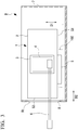
- Fig. 3 is a diagram illustrating the minimum structure of a server according to the second embodiment.
- the server 9 comprises at least a module 1 and a housing 7.
- the module 1 is similar to that indicated for the above-described first embodiment. That is, the module 1 comprises at least a substrate 2, a cooling unit 3, a connection terminal portion 5 and a connection pipe 6.
- a heat-generating component 4 is provided on the substrate 2.
- the cooling unit 3 cools the heat-generating component 4 provided on the substrate 2.
- connection terminal portion 5 is provided on the substrate 2.
- the connection terminal portion 5 is inserted or withdrawn in the insertion/withdrawal direction D1, which intersects the edge S1 of the substrate 2 on which the connection terminal portion 5 is provided.
- connection pipe 6 is connected to the cooling unit 3.
- the connection pipe 6 extends in the direction D2, which is different from the insertion/withdrawal direction D1 of the connection terminal portion 5.
- the connection pipe 6 extends from the side towards the connection terminal portion 5.
- the housing 7 houses the module 1.
- the housing 7 has an opening portion 8.
- the opening portion 8 faces the edge S2 of the substrate 2 from which the connection pipe 6 extends.
- connection pipe 6 extends to the outside the housing 7 through the opening portion 8.
- connection pipe 6 which extends to the outside of the housing 7 through the opening portion 8, is displaced together with the substrate 2, in the insertion/withdrawal direction of the substrate 2, inside the opening portion 8.
- the connection pipe 6 is provided on the side towards the connection terminal portion 5, so that even if the substrate 2 is displaced in the insertion/withdrawal direction D1 of the connection terminal portion 5 when inserting or withdrawing the connection terminal portion 5, the connection pipe 6 does not tend to interfere with the inner rim 8t of the opening 8.
- this server 9 it is possible to easily insert or withdraw the module 1 comprising the connection pipe 6 extending in the direction D2 different from the insertion/withdrawal direction D1 of the connection terminal portion 5.
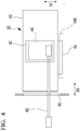
- Fig. 4 is a diagram illustrating the minimum structure of a module according to the third embodiment.
- the module 1C comprises at least a substrate 2C, a cooling unit 3C, a connection terminal portion 5C and a connection pipe 6C.
- the substrate 2C is provided with a heat-generating component 4C.
- the cooling unit 3C cools the heat-generating component 4C provided on the substrate 2C.
- connection terminal portion 5C is provided on the substrate 2C.
- the connection terminal portion 5C is inserted and withdrawn with respect to an external connector 100 or the like.
- connection pipe 6C is connected to the cooling unit 3C.
- the connection pipe 6C is connected to the cooling unit 3C through an opening 8C provided in a direction D2 different from the insertion/withdrawal direction D1 of the connection terminal portion 5C.
- the connection pipe 6C is provided at a position not interfering with the opening 8C when the connection terminal portion 5C is being inserted or withdrawn.
- connection pipe 6C is provided at a position not interfering with the opening 8C when the connection terminal portion 5C is being inserted or withdrawn. Therefore, when the substrate 2C is displaced in the insertion/withdrawal direction D1 in order to insert or withdraw the connection terminal portion 5C with respect to the connector 100, the connection pipe 6C does not interfere with the opening 8C. As a result thereof, the module 1C comprising the connection pipe 6C connected to the cooling unit 3C through the opening 8C is less susceptible to interfere from other components and the like, and the substrate 2C can be easily inserted or withdrawn.
- Fig. 5 is a vertical section view illustrating the structure of a server according to the fourth embodiment.
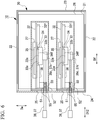
- Fig. 6 is a horizontal section view illustrating the structure of the server according to the fourth embodiment.
- the server 10 of the present embodiment comprises a housing 20 and a module 30.
- the housing 20 is in the shape of a hollow box and is contained in a server rack, which is not illustrated.
- the housing 20 is supported so as to be able to slide in a horizontal direction (hereinafter referred to as the front-rear direction Df) connecting one end of the server rack (not illustrated) with the other end.
- the housing 20 contains, in the interior thereof, a base substrate 26, a module 30, a power supply device (not illustrated) and the like.
- the housing 20 comprises a bottom plate 21, side plates 22, a front plate 23 and a rear plate 24.
- the bottom plate 21, in plan view, is rectangular, having long edges in the front-rear direction Df and having short edges in the width direction Dw orthogonal to the front-rear direction Df.
- the side plates 22 are located on both sides, in the width direction Dw, of the bottom plate 21.
- the side plates 22 respectively extend upward, in the vertical direction Dv, from both sides, in the width direction Dw, of the bottom plate 21.
- the front plate 23 is located on one end, in the front-rear direction Df, of the bottom plate 21.
- the front plate 23 extends upward from the front end of the bottom plate 21.
- the rear plate 24 is located on the other end, in the front-rear direction Df, of the bottom plate 21.
- the rear plate 24 extends upward from the rear end of the bottom plate 21.
- the rear plate 24 has opening portions 25 penetrating therethrough in the front-rear direction Df.
- a plurality of the opening portions 25 are provided so as to be spaced apart in the width direction Dw.
- the base substrate 26 is plate-shaped and is provided along the bottom plate 21 of the housing 20.
- the base substrate 26 has a connector 27 on the upper surface thereof.
- a connection terminal portion 35 of the module 30 to be mentioned below is connected to the connector 27.
- the module 30 comprises a substrate 32, a cooling unit 33, a supply connection pipe (connection pipe) 36, a discharge connection pipe (connection pipe) 37 and a fixation portion 50.
- the substrate 32 is in the shape of a rectangular plate having short edges (pipe-extending edge) S12 and long edges S11.
- the substrate 32 is arranged so that the long edges S11 are aligned with the front-rear direction Df and the short edges S12 are aligned with the vertical direction Dv, in the state in which the module 30 is contained inside the housing 20.
- the substrate 32 has a connection terminal portion 35.
- the connection terminal portion 35 is provided on one of the long edges S11 on the substrate 32.
- the connection terminal portion 35 is provided on the long edge S11 located on the lower side, in the vertical direction Dv, in the state in which the module 30 is contained inside the housing 20.
- the connection terminal portion 35 is inserted and withdrawn with respect to the connector 27 on the base substrate 26 inside the housing 20.
- the insertion/withdrawal direction D11 of the connection terminal portion 35 with respect to the connector 27 is a direction orthogonal to the upper surface of the base substrate 26, i.e., the vertical direction Dv.
- the substrate 32 has a heat-generating component 34 such as a CPU (Central Processing Unit).
- the heat-generating component 34 is mounted on one surface 32f of the substrate 32.
- the cooling unit 33 is provided on the substrate 32.
- the cooling unit 33 is provided so as to be stacked on the heat-generating component 34. More specifically, the cooling unit 33 should preferably have a structure such that, when stacked on the substrate 32, there is contact over as large an area as possible and there is tight contact with as large a contact force as possible, so that heat is transferred with the lowest possible contact resistance.
- the cooling unit 33 cools the heat-generating component 34.
- the cooling unit 33 has a rectangular shape that is larger than the heat-generating component 34 when viewed from a direction orthogonal to the one surface 32f of the substrate 32.
- the cooling unit 33 has a prescribed thickness in the direction orthogonal to the one surface 32f of the substrate 32.
- the cooling unit 33 has a recess 33s in a first surface 33a facing the heat-generating component 34.
- the recess 33s is recessed from the first surface 33a towards a second surface 33b on the side opposite thereto.
- the recess 33s covers at least a portion of the surface 34f of the heat-generating component 34.
- the supply connection pipe 36 and the discharge connection pipe 37 are connected to the cooling unit 33.
- the supply connection pipe 36 supplies a coolant to the cooling unit 33.
- the supply connection pipe 36 has, for example, an elbow-shaped connection portion 36c on one end.
- the connection portion 36c on the supply connection pipe 36 is connected to the cooling unit 33.
- the connection portion 36c is arranged to be on one side, relative to the center of the heat-generating component 34, in the recess 33s in the cooling unit 33.
- the connection portion 36c is arranged to be, for example, on the lower side, in the vertical direction Dv, relative to the center of the heat-generating component 34, in the state in which the module 30 is contained inside the housing 20.
- the supply connection pipe 36 extends to the outside of the substrate 32.
- the supply connection pipe 36 extends from the substrate 32 in the direction D12, which is different from the insertion/withdrawal direction D11 of the connection terminal portion 35.
- the supply connection pipe 36 extends to the outside of the substrate 32 from a short edge S12 of the substrate 32, which is different from the long edge S11 on which the connection terminal portion 35 is provided.
- the supply connection pipe 36 is connected to a supply pipe (not illustrated).
- the supply pipe (not illustrated) supplies the supply connection pipe 36 with a coolant supplied from coolant supply equipment (not illustrated).
- the discharge connection pipe 37 discharges the coolant from the cooling unit 33.
- the discharge connection pipe 37 is provided alongside the supply connection pipe 36 in a direction along the one surface 32f of the substrate 32.
- the discharge connection pipe 37 has a connection portion 37c on one end.
- the connection portion 37c on the discharge connection pipe 37 is connected to the cooling unit 33.
- the connection portion 37c is arranged to be on the other side, relative to the center of the heat-generating component 34, in the recess 33s in the cooling unit 33.
- the connection portion 37c is arranged to be, for example, on the upper side, in the vertical direction Dv, relative to the center of the heat-generating component 34, in the state in which the module 30 is contained inside the housing 20.
- the discharge connection pipe 37 extends to the outside of the substrate 32.
- the discharge connection pipe 37 extends from the substrate 32 in the direction D12, which is different from the insertion/withdrawal direction D11 of the connection terminal 35.
- the discharge connection pipe 37 extends to the outside of the substrate 32 from a short edge S12 of the substrate 32, which is different from the long edge S11 on which the connection terminal portion 35 is provided.
- the discharge connection pipe 37 is connected to a discharge pipe (not illustrated) that discharges the coolant to the outside.
- the supply connection pipe 36 and the discharge connection pipe 37 extend from extension positions P1 and P2 that are located, on the short edge S12 of the substrate 32 from which the supply connection pipe 36 and the discharge connection pipe 37 extend, on the side towards the connection terminal portion 35 relative to the center Sd of the short edge S12.
- the supply connection pipe 36 and the discharge connection pipe 37 extend from extension positions P1 and P2, on the short edge S12, which are closer to the long edge S11 on which the connection terminal portion 35 is provided than the center Sd is.
- the supply connection pipe 36 and the discharge connection pipe 37 are connected to the cooling unit 33 at connection positions P3 and P4 that are shifted towards the side opposite (the upper side in Fig. 5 ) to the side (the side towards the base substrate 26, the lower side in Fig. 5 ) on which the connection terminal portion 35 is provided, relative to the extension positions P1 and P2 from which the supply connection pipe 36 and the discharge connection pipe 37 extend from the pipe-extending short edge S12.
- the supply connection pipe 36 and the discharge connection pipe 37 are curved towards the side on which the connection terminal portion 35 is provided. Furthermore, the supply connection pipe 36 and the discharge connection pipe 37 extend from the cooling unit 33 in mutually different directions. For example, the supply connection pipe 36 and the discharge connection pipe 37 extend with different orientations. Specifically, the connection portion 36c of the supply connection pipe 36 and the connection portion 37c of the discharge connection pipe 37 are not parallel to each other when viewed from a direction orthogonal to the one surface 32f of the substrate 32. The connection portion 36c of the supply connection pipe 36 and the connection portion 37c of the discharge connection pipe 37 are both inclined relative to the direction parallel to the long edges S11 of the substrate 32. The inclination angle of the connection portion 37c of the discharge connection pipe 37 relative to the direction parallel to the long edges S11 is greater than the inclination angle of the connection portion 36c of the supply connection pipe 36.
- the fixation portion 50 fixes the supply connection pipe 36 and the discharge connection pipe 37.
- the fixation portion 50 is provided at a position at which stress from the supply connection pipe 36 and the discharge connection pipe 37 to the cooling unit 33 is reduced. Specifically, the fixation portion 50 fixes the supply connection pipe 36 and the discharge connection pipe 37 at positions distanced from the connection portions 36c and 37c connected to the cooling unit 33.
- the fixation portion 50 constrains the movement of the supply connection pipe 36 and the discharge connection pipe 37 in the pipe axial directions.
- the fixation portion 50 fixes the supply connection pipe 36 and the discharge connection pipe 37 on the short edge S12 of the substrate 32 from which the supply connection pipe 36 and the discharge connection pipe 37 extend.
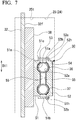
- Fig. 7 is a section view illustrating the structure of the fixation portion in the fourth embodiment.
- the fixation portion 50 is attached to a reinforcement member 38.
- the reinforcement member 38 is arranged parallel to the substrate 32.
- the reinforcement member 38 is provided on the one surface 32f of the substrate 32 at a portion where the cooling unit 33 is not provided.
- the reinforcement member 38 comprises, for example, an aluminum alloy or the like.
- the reinforcement member 38 has the function of reinforcing the substrate 32 and the function of receiving heat transferred from various types of electronic components mounted on the one surface 32f of the substrate 32 and dissipating the heat.
- the fixation portion 50 has a base member 51, a clamp member 52 and a spacer 53.
- the base member 51 is fixed to the reinforcement member 38.
- the base member 51 may be formed integrally with the reinforcement member 38.
- the base member 51 has a receiving recess 51a, an engagement portion 51b and a pedestal portion 51c.
- the receiving recess 51a accommodates portions, in the radial direction, of the supply connection pipe 36 and the discharge connection pipe 37.
- the engagement portion 51b is provided on one side of the receiving recess 51a and extends away from the reinforcement member 38 and towards the clamp member 52.
- the engagement portion 51b has an engagement hole 51h for engaging with the clamp member 52.
- the pedestal portion 51c is provided on the other side of the receiving recess 51a.
- the pedestal portion 51c is located on the side opposite to the engagement portion 51b with the receiving recess 51a therebetween.
- the pedestal portion 51c has a female screw hole 51n.
- the clamp member 52 faces the base member 51 on the side away from the reinforcement member 38.
- the clamp member 52 has a receiving recess 52a, an engagement claw 52b and a flange portion 52c.
- the receiving recess 52a accommodates portions, in the radial direction, of the supply connection pipe 36 and the discharge connection pipe 37.
- the engagement claw 52b is provided on one side of the receiving recess 52a.
- the engagement claw 52b engages with the engagement hole 51h on the engagement portion 51b of the base member 51.
- the flange portion 52c is provided on the other side of the receiving recess 52a.
- the flange portion 52c is located on the side opposite to the engagement claw 52b with the receiving recess 52a therebetween.
- the flange portion 52c has a screw penetration hole 52h.
- the spacer 53 is arranged between the pedestal portion 51c of the base member 51 and the flange portion 52c of the clamp member 52.
- the spacer 53 is tubular and has a through hole 53h.
- the supply connection pipe 36 and the discharge connection pipe 37 are sandwiched between the receiving recess 51a in the base member 51 and the receiving recess 52a in the clamp member 52.
- the clamp member 52 is restricted from moving in the direction away from the reinforcement member 38 on one side of the receiving recess 52a by the engagement claw 52b being engaged with the engagement hole 51h.
- the clamp member 52 is fastened to the base member 51 by a screw 54 on the other side of the receiving recess 52a.
- the screw 54 is passed through the screw penetration hole 52h in the flange portion 52c of the clamp member 52 and the through hole 53h in the spacer 53, and is screwed into the female screw hole 51n in the pedestal portion 51c of the base member 51.
- the spacing between the flange portion 52c of the clamp member 52 and the pedestal portion 51c of the base member 51 is regulated by the spacer 53.
- the supply connection pipe 36 and the discharge connection pipe 37 sandwiched between the receiving recess 51a of the base member 51 and the receiving recess 52a of the clamp member 52 can be kept from being excessively crushed in the radial direction.
- the supply connection pipe 36 and the discharge connection pipe 37 fixed by the fixation portion 50 are spaced (the spacing from the substrate 32 in a direction orthogonal to the one surface 32f of the substrate 32) from the substrate 32 by the same distance at the parts connected to the cooling unit 33 and at the parts fixed to the fixation portion 50.
- the supply connection pipe 36 and the discharge connection pipe 37 are curved between the parts fixed to the fixation portion 50 and the connection portions 36c and 37c, which are the parts connected to the cooling unit 33.
- elastic sheets 55 are sandwiched between the base member 51 and the clamp member 52 of the fixation portion 50, and the supply connection pipe 36 and the discharge connection pipe 37.
- the elastic sheets 55 comprise a rubber-based material or the like, and have elasticity. Due to the elastic sheets 55, a compressive force in the radial direction is applied to the supply connection pipe 36 and the discharge connection pipe 37 sandwiched by the receiving recess 51a in the base member 51 and the receiving recess 52a in the clamp member 52.
- the elastic sheets 55 are elastically deformed in the thickness directions thereof, thereby reducing the compressive force in the radial direction applied to the supply connection pipe 36 and the discharge connection pipe 37.
- the elastic sheets 55 due to the friction with the supply connection pipe 36 and the discharge connection pipe 37, keep the supply connection pipe 36 and the discharge connection pipe 37 from shifting in the pipe axial direction. Furthermore, the elastic sheets 55 are provided, in a state of compression in the thickness directions thereof, between the base member 51 and the clamp member 52 of the fixation portion 50, and the supply connection pipe 36 and the discharge connection pipe 37, thereby increasing the friction generated with respect to the supply connection pipe 36 and the discharge connection pipe 37. As a result thereof, the shifting of the supply connection pipe 36 and the discharge connection pipe 37 in the pipe axial direction can be more reliably suppressed.
- the supply connection pipe 36 and the discharge connection pipe 37 extend to the outside of the housing 20 through an opening portion 25 formed in the rear plate 24 of the housing 20, in a state in which the module 30 is contained inside the housing 20.
- the elastic sheets 55 extend from the fixation portion 50 to the inside of the opening portion 25.
- the elastic sheets 55 are located between the inner rim of the opening portion 25, and the supply connection pipe 36 and the discharge connection pipe 37. As a result thereof, the supply connection pipe 36 and the discharge connection pipe 37 are kept from scraping against the inner rim of the opening portion 25.
- the module 30 as described above can be attached to or detached from the housing 20.
- the connection terminal portion 35 is inserted or withdrawn with respect to the connector 27 in the base substrate 26 in the housing 20.
- the substrate 32 is inserted or withdrawn in the insertion/withdrawal direction D11, which intersects the long edge S11 of the substrate 32 on which the connection terminal portion 35 is provided.
- the substrate 32 When withdrawing the connection terminal portion 35 from the connector 27, the substrate 32 is displaced in the direction away from the connection terminal portion 35 in the insertion/withdrawal direction D11 intersecting the long edge S11 on which the connection terminal portion 35 is provided.
- the supply connection pipe 36 and the discharge connection pipe 37 extend from a side of the short edge S12 towards the connection terminal portion 35 relative to the center Sd. For this reason, there is no tendency to interfere with other components such as, for example, the inner rim 25t of the opening portion 25, located on the side opposite to the connection terminal portion 35.
- the supply connection pipe 36 and the discharge connection pipe 37 extend from the side towards the connection terminal portion 35.
- the supply connection pipe 36 and the discharge connection pipe 37 do not tend to interfere with the inner rim 25t of the opening portion 25 located on the side opposite to the connection terminal portion 35. Therefore, in a module 30 comprising a supply connection pipe 36 and a discharge connection pipe 37 extending in a direction D12 different from the insertion/withdrawal direction D11 of the connection terminal portion 35, the substrate 32 can be easily inserted and withdrawn.
- the supply connection pipe 36 and the discharge connection pipe 37 extend from a side towards the connection terminal portion 35 relative to the center Sd of the short edge S12.
- the supply connection pipe 36 and the discharge connection pipe 37 do not tend to interfere with the inner rim 25t of the opening portion 25 located on the side opposite to the connection terminal portion 35. Therefore, in the module 30 comprising the supply connection pipe 36 and the discharge connection pipe 37 extending in a direction D12 different from the insertion/withdrawal direction D11 of the connection terminal portion 35, the substrate 32 can be easily inserted and withdrawn.
- the supply connection pipe 36 and the discharge connection pipe 37 are connected to the cooling unit 33 at connection positions P3 and P4 that are shifted towards the side opposite to the side on which the connection terminal portion 35 is provided, relative to the extension positions P1 and P2 from which the supply connection pipe 36 and the discharge connection pipe 37 extend from the pipe-extending short edge S12.
- the supply connection pipe 36 and the discharge connection pipe 37 are arranged to extend, from the connection portions 36c and 37c connected to the cooling unit 33, towards the connection terminal portion 35.
- the supply connection pipe 36 and the discharge connection pipe 37 can be extended from the connection terminal portion 35 to the outside of the substrate 32.
- the supply connection pipe 36 and the discharge connection pipe 37 extend from the cooling unit 33 in mutually different directions.
- the supply connection pipe 36 and the discharge connection pipe 37 extend with mutually different orientations.
- the connection positions P3 and P4 if the supply connection pipe 36 and the discharge connection pipe 37 were extended in the same direction and made parallel, then the curvature of one of the supply connection pipe 36 and the discharge connection pipe 37 could become smaller in some cases. If the curvature became smaller, then a load would be applied to one of the supply connection pipe 36 and the discharge connection pipe 37, and the flow channel in the pipe could be crushed in some cases.
- the curvature can be kept from becoming smaller in both the supply connection pipe 36 and the discharge connection pipe 37. Therefore, the load generated on both the supply connection pipe 36 and the discharge connection pipe 37 can be suppressed, thereby keeping the flow channels in the pipes from being crushed. As a result thereof, the flow resistance of the coolant in the supply connection pipe 36 and the discharge connection pipe 37 can be kept from increasing, and high cooling efficiency can be obtained.
- the supply connection pipe 36 and the discharge connection pipe 37 are fixed by the fixation portion 50.
- the fixation portion 50 As a result thereof, even if the supply connection pipe 36 and the discharge connection pipe 37 move outside the module 30, the movement of the supply connection pipe 36 and the discharge connection pipe 37 is not easily transmitted past the fixation portion 50 towards the cooling unit 33. Therefore, stress applied from the supply connection pipe 36 and the discharge connection pipe 37 to the cooling unit 33 can be reduced. As a result thereof, it is possible to keep too much force from being applied to the cooling unit 33, or to the connection portions for connecting the supply connection pipe 36 and the discharge connection pipe 37 to the cooling unit 33, thereby preventing leakage of the coolant and the like.
- the supply connection pipe 36 and the discharge connection pipe 37 extend through the opening portions 25 to the outside of the housing 20.
- the supply connection pipe 36 and the discharge connection pipe 37 are displaced, together with the substrate 32, in the insertion/withdrawal direction D11 of the substrate 32, inside the opening portion 25.
- the supply connection pipe 36 and the discharge connection pipe 37 are provided on the short edge S12 on the side towards the connection terminal portion 35, and thus do not tend to interfere with the inner rim 25t of the opening portion 25. Therefore, the substrate 32 can be easily inserted and withdrawn.
- the fixation portion 50 constrains the supply connection pipe 36 and the discharge connection pipe 37 in the pipe axial direction, but it is not always essential for the supply connection pipe 36 and the discharge connection pipe 37 to be constrained in the pipe axial direction. In other words, it is sufficient for the fixation portion 50 to reduce the stress transmitted from the supply connection pipe 36 and the discharge connection pipe 37 to the cooling unit 33.
- the cooling unit 33 cools only the heat-generating component 34, but other electronic components provided on the substrate 32 may also be cooled. Additionally, the heat transfer between the heat-generating component and the cooling unit is not limited to being made through direct contact, and may be mediated by an electrically insulating thin-film (mica) or a fluid such as grease, or mediated by an intermediary member formed from a material having good thermal conductivity.
- a substrate in the module, which is provided with a connection pipe extending in a direction different from the insertion/withdrawal direction of a connection terminal portion, a substrate can be easily inserted and withdrawn.
Landscapes
- Engineering & Computer Science (AREA)
- General Engineering & Computer Science (AREA)
- Physics & Mathematics (AREA)
- Computer Hardware Design (AREA)
- Thermal Sciences (AREA)
- Microelectronics & Electronic Packaging (AREA)
- Theoretical Computer Science (AREA)
- Human Computer Interaction (AREA)
- General Physics & Mathematics (AREA)
- Cooling Or The Like Of Semiconductors Or Solid State Devices (AREA)
- Cooling Or The Like Of Electrical Apparatus (AREA)
Abstract
Description
- The present invention relates to a module, and a server.
-
Patent Document 1 discloses a configuration provided with a cooling block for cooling electronic components on a printed circuit board. In this configuration, cooling pipes through which a refrigerant flows are connected to the cooling block. Additionally, the printed circuit board has a connector on one edge of the printed circuit board. The cooling pipes extend to the outside of the printed circuit board from an edge of the printed circuit board opposite to the edge on which the connector is provided. The connector insertion/withdrawal direction of the printed circuit board is aligned with the connection direction of the cooling pipe. -
Patent Document 2 discloses a configuration provided with a cooling plate for cooling electronic components on a printed circuit board. In this configuration, the cooling plate is provided with a cooling channel through which a refrigerant flows. Additionally, the printed circuit board has a socket that can be inserted or withdrawn with respect to a connector. Hose nipples provided on the ends of the cooling channel are disposed on an edge of the printed circuit board on which the socket is provided. The insertion/withdrawal direction of the socket on the printed circuit board is aligned with the connection direction of the hose nipples. -
- [Patent Document 1]
Japanese Unexamined Patent Application, First Publication No2000-338173 - [Patent Document 2]
Japanese Unexamined Patent Application, First Publication NoH10-70386 - There are cases in which the insertion/withdrawal direction of a printed circuit board is made different from the connection direction of cooling piping (cooling pipes, hose nipples). In such cases, when inserting or removing the printed circuit board, the cooling pipes extending from the printed circuit board can interfere with other components, making it difficult to insert and withdraw the printed circuit board.
-
Patent Documents Patent Documents - The present invention was made in view of the above-mentioned problem, and provides a module and a server wherein, in the module, which is provided with a connection pipe extending in a direction different from the insertion/withdrawal direction of a connection terminal portion, a substrate can be easily inserted and withdrawn.
- A module according to one embodiment of the present invention includes a substrate; a cooling unit that cools a heat-generating component provided on the substrate; a connection terminal portion provided on the substrate; and a connection pipe that is connected to the cooling unit and that extends in a direction different from a direction of at least one of insertion and withdrawal of the connection terminal portion, wherein the connection pipe extends from a side towards the connection terminal portion.
- A server according to one embodiment of the present invention includes a module as mentioned above; and a housing containing the module; wherein the housing has an opening portion that faces the edge of the substrate from which the connection pipe extends; and the connection pipe extends through the opening portion to an outside of the housing.
- A module according to one embodiment of the present invention includes a substrate; a cooling unit that cools a heat-generating component provided on the substrate; a connection terminal portion provided on the substrate; and a connection pipe that is connected to the cooling unit through an opening provided in a direction different from a direction of at least one of insertion and withdrawal of the connection terminal, wherein the connection pipe is provided at a position not interfering with the opening when the connection terminal portion is being inserted or withdrawn.
- According to the module and the server in the present invention, in the module, which is provided with a connection pipe extending in a direction different from the insertion/withdrawal direction of a connection terminal portion, a substrate can be easily inserted and withdrawn.
-
-
Fig. 1 is a diagram illustrating the minimum structure of a module according to a first embodiment. -
Fig. 2 is a diagram illustrating the minimum structure of a module according to a modified example of the first embodiment. -
Fig. 3 is a diagram illustrating the minimum structure of a server according to a second embodiment. -
Fig. 4 is a diagram illustrating the minimum structure of a module according to a third embodiment. -
Fig. 5 is a vertical section view illustrating the structure of a server according to a fourth embodiment. -
Fig. 6 is a horizontal section view illustrating the structure of a server according to the fourth embodiment. -
Fig. 7 is a section view illustrating the structure of a fixation portion according to the fourth embodiment. - Multiple embodiments of the present invention will be explained below with reference to the drawings. However, regarding the present embodiments, the portions that are identical to the aforementioned conventional examples will be referred to by using the same names, and their explanations will be omitted.
-
Fig. 1 is a diagram illustrating the minimum structure of a module according to the first embodiment. - As illustrated in this drawing, it is sufficient for the
module 1 to comprise at least asubstrate 2, acooling unit 3, aconnection terminal portion 5 and aconnection pipe 6. - A heat-
generating component 4 is provided on thesubstrate 2. Thecooling unit 3 cools the heat-generating component 4 provided on thesubstrate 2. - The
connection terminal portion 5 is provided on thesubstrate 2. Theconnection terminal portion 5 is inserted and withdrawn with respect to anexternal connector 100 or the like. When inserting or withdrawing theconnection terminal portion 5 with respect to theconnector 100 or the like, theconnection terminal portion 5 is inserted or withdrawn in the insertion/withdrawal direction D1, which intersects an edge S1 of thesubstrate 2 on which theconnection terminal portion 5 is provided. - The
connection pipe 6 is connected to thecooling unit 3. Theconnection pipe 6 extends in the direction D2, which is different from the insertion/withdrawal direction D1 of theconnection terminal portion 5. On an edge S2 of thesubstrate 2 from which theconnection pipe 6 extends, theconnection pipe 6 extends from the side towards theconnection terminal portion 5. For example, theconnection pipe 6 extends from a portion of the edge S2 near the edge S1 on which theconnection terminal portion 5 is provided. - With this
module 1, when inserting or withdrawing theconnection terminal portion 5 with respect to theexternal connector 100 or the like, thesubstrate 2 is inserted or withdrawn in the insertion/withdrawal direction D1 intersecting the edge S1 of thesubstrate 2 on which theconnection terminal portion 5 is provided. For example, when withdrawing theconnection terminal portion 5 from theconnector 100, thesubstrate 2 is displaced in a direction away from theconnection terminal portion 5 in the insertion/withdrawal direction D1 intersecting the edge S1 on which theconnection terminal portion 5 is provided. When connecting theconnection terminal portion 5 to theconnector 100, thesubstrate 2 is displaced towards theconnection terminal portion 5 in the insertion/withdrawal direction D1 intersecting the edge S1 on which theconnection terminal portion 5 is provided. - As mentioned above, the
connection pipe 6 extends from the side towards theconnection terminal portion 5. In other words, on the edge S2 from which theconnection pipe 6 extends, theconnection pipe 6 is not located on the side opposite to theconnection terminal portion 5. Therefore, when thesubstrate 2 is displaced in the insertion/withdrawal direction D1 intersecting the edge S1 on which theconnection terminal portion 5 is provided in order to insert or withdraw theconnection terminal portion 5 with respect to theconnector 100, theconnection pipe 6 does not tend to interfere with other components or the like located on the side opposite to theconnection terminal portion 5. As a result thereof, themodule 1 comprising theconnection pipe 6 extending in the direction D2 different from the insertion/withdrawal direction D1 of theconnection terminal portion 5 is less susceptible to interfere from other components or the like, and thesubstrate 2 can be easily inserted or withdrawn. -
Fig. 2 is a diagram illustrating the minimum structure of a module according to a modified example of the first embodiment. - In the above-mentioned first embodiment, the
substrate 2B was rectangular, but the invention is not limited thereto. For example, the substrate may have a cutout portion. - As illustrated in
Fig. 2 , on thesubstrate 2B of themodule 1B, a cutout portion K is formed on the edge S2B of thesubstrate 2B from which theconnection pipe 6 extends. The cutout portion K is formed, for example, by recessing a portion of thesubstrate 2B inward, in stepped fashion, towards the inner side of thesubstrate 2B. - With the
substrate 2B having the cutout portion K, on the edge S2B from which theconnection pipe 6 extends, theconnection pipe 6 extends from the side towards theconnection terminal portion 5. - In this
module 1B also, theconnection pipe 6 extends from the side towards theconnection terminal portion 5. In other words, on the edge S2B from which theconnection pipe 6 extends, theconnection pipe 6 is not located on the side opposite to theconnection terminal portion 5. Therefore, when thesubstrate 2B is displaced in the insertion/withdrawal direction D1 intersecting the edge S1 on which theconnection terminal portion 5 is provided in order to insert or withdraw theconnection terminal portion 5 with respect to theconnector 100, theconnection pipe 6 does not tend to interfere with other components or the like located on the side opposite to theconnection terminal portion 5. As a result thereof, themodule 1B comprising theconnection pipe 6 extending in the direction D2 different from the insertion/withdrawal direction D1 of theconnection terminal portion 5 is less susceptible to interfere from components or the like, and thesubstrate 2B can be easily inserted and withdrawn. - In
Figs. 1 and2 illustrating the present embodiment and the modified example thereof, theconnection terminal portion 5 is provided on an edge on an outer peripheral portion of thesubstrate 2, but the position of theconnection terminal portion 5 is not limited thereto. -
Fig. 3 is a diagram illustrating the minimum structure of a server according to the second embodiment. - As illustrated in this drawing, it is sufficient for the
server 9 to comprise at least amodule 1 and a housing 7. - The
module 1 is similar to that indicated for the above-described first embodiment. That is, themodule 1 comprises at least asubstrate 2, acooling unit 3, aconnection terminal portion 5 and aconnection pipe 6. - A heat-generating
component 4 is provided on thesubstrate 2. Thecooling unit 3 cools the heat-generatingcomponent 4 provided on thesubstrate 2. - The
connection terminal portion 5 is provided on thesubstrate 2. When inserting or withdrawing theconnection terminal portion 5 with respect to aconnector 100 or the like, theconnection terminal portion 5 is inserted or withdrawn in the insertion/withdrawal direction D1, which intersects the edge S1 of thesubstrate 2 on which theconnection terminal portion 5 is provided. - The
connection pipe 6 is connected to thecooling unit 3. Theconnection pipe 6 extends in the direction D2, which is different from the insertion/withdrawal direction D1 of theconnection terminal portion 5. On the edge S2 of thesubstrate 2 from which theconnection pipe 6 extends, theconnection pipe 6 extends from the side towards theconnection terminal portion 5. - The housing 7 houses the
module 1. The housing 7 has an opening portion 8. The opening portion 8 faces the edge S2 of thesubstrate 2 from which theconnection pipe 6 extends. - The
connection pipe 6 extends to the outside the housing 7 through the opening portion 8. - In this
server 9, when inserting or withdrawing thesubstrate 2 of themodule 1, theconnection pipe 6, which extends to the outside of the housing 7 through the opening portion 8, is displaced together with thesubstrate 2, in the insertion/withdrawal direction of thesubstrate 2, inside the opening portion 8. On the edge S2 from which theconnection pipe 6 extends, theconnection pipe 6 is provided on the side towards theconnection terminal portion 5, so that even if thesubstrate 2 is displaced in the insertion/withdrawal direction D1 of theconnection terminal portion 5 when inserting or withdrawing theconnection terminal portion 5, theconnection pipe 6 does not tend to interfere with theinner rim 8t of the opening 8. As a result thereof, with thisserver 9, it is possible to easily insert or withdraw themodule 1 comprising theconnection pipe 6 extending in the direction D2 different from the insertion/withdrawal direction D1 of theconnection terminal portion 5. -
Fig. 4 is a diagram illustrating the minimum structure of a module according to the third embodiment. - As illustrated in this drawing, it is sufficient for the
module 1C to comprise at least asubstrate 2C, acooling unit 3C, aconnection terminal portion 5C and aconnection pipe 6C. - The
substrate 2C is provided with a heat-generatingcomponent 4C. Thecooling unit 3C cools the heat-generatingcomponent 4C provided on thesubstrate 2C. - The
connection terminal portion 5C is provided on thesubstrate 2C. Theconnection terminal portion 5C is inserted and withdrawn with respect to anexternal connector 100 or the like. - The
connection pipe 6C is connected to thecooling unit 3C. Theconnection pipe 6C is connected to thecooling unit 3C through anopening 8C provided in a direction D2 different from the insertion/withdrawal direction D1 of theconnection terminal portion 5C. Theconnection pipe 6C is provided at a position not interfering with the opening 8C when theconnection terminal portion 5C is being inserted or withdrawn. - In this
module 1C, theconnection pipe 6C is provided at a position not interfering with the opening 8C when theconnection terminal portion 5C is being inserted or withdrawn. Therefore, when thesubstrate 2C is displaced in the insertion/withdrawal direction D1 in order to insert or withdraw theconnection terminal portion 5C with respect to theconnector 100, theconnection pipe 6C does not interfere with theopening 8C. As a result thereof, themodule 1C comprising theconnection pipe 6C connected to thecooling unit 3C through the opening 8C is less susceptible to interfere from other components and the like, and thesubstrate 2C can be easily inserted or withdrawn. -
Fig. 5 is a vertical section view illustrating the structure of a server according to the fourth embodiment.Fig. 6 is a horizontal section view illustrating the structure of the server according to the fourth embodiment. - As illustrated in
Fig. 5 andFig. 6 , theserver 10 of the present embodiment comprises ahousing 20 and amodule 30. - The
housing 20 is in the shape of a hollow box and is contained in a server rack, which is not illustrated. Thehousing 20 is supported so as to be able to slide in a horizontal direction (hereinafter referred to as the front-rear direction Df) connecting one end of the server rack (not illustrated) with the other end. Thehousing 20 contains, in the interior thereof, abase substrate 26, amodule 30, a power supply device (not illustrated) and the like. - The
housing 20 comprises abottom plate 21,side plates 22, afront plate 23 and arear plate 24. - The
bottom plate 21, in plan view, is rectangular, having long edges in the front-rear direction Df and having short edges in the width direction Dw orthogonal to the front-rear direction Df. Theside plates 22 are located on both sides, in the width direction Dw, of thebottom plate 21. Theside plates 22 respectively extend upward, in the vertical direction Dv, from both sides, in the width direction Dw, of thebottom plate 21. Thefront plate 23 is located on one end, in the front-rear direction Df, of thebottom plate 21. Thefront plate 23 extends upward from the front end of thebottom plate 21. Therear plate 24 is located on the other end, in the front-rear direction Df, of thebottom plate 21. Therear plate 24 extends upward from the rear end of thebottom plate 21. - The
rear plate 24 has openingportions 25 penetrating therethrough in the front-rear direction Df. A plurality of the openingportions 25 are provided so as to be spaced apart in the width direction Dw. - The
base substrate 26 is plate-shaped and is provided along thebottom plate 21 of thehousing 20. Thebase substrate 26 has aconnector 27 on the upper surface thereof. Aconnection terminal portion 35 of themodule 30 to be mentioned below is connected to theconnector 27. - The
module 30 comprises asubstrate 32, a coolingunit 33, a supply connection pipe (connection pipe) 36, a discharge connection pipe (connection pipe) 37 and afixation portion 50. - The
substrate 32 is in the shape of a rectangular plate having short edges (pipe-extending edge) S12 and long edges S11. Thesubstrate 32 is arranged so that the long edges S11 are aligned with the front-rear direction Df and the short edges S12 are aligned with the vertical direction Dv, in the state in which themodule 30 is contained inside thehousing 20. - The
substrate 32 has aconnection terminal portion 35. Theconnection terminal portion 35 is provided on one of the long edges S11 on thesubstrate 32. Theconnection terminal portion 35 is provided on the long edge S11 located on the lower side, in the vertical direction Dv, in the state in which themodule 30 is contained inside thehousing 20. Theconnection terminal portion 35 is inserted and withdrawn with respect to theconnector 27 on thebase substrate 26 inside thehousing 20. The insertion/withdrawal direction D11 of theconnection terminal portion 35 with respect to theconnector 27 is a direction orthogonal to the upper surface of thebase substrate 26, i.e., the vertical direction Dv. - The
substrate 32 has a heat-generatingcomponent 34 such as a CPU (Central Processing Unit). The heat-generatingcomponent 34 is mounted on onesurface 32f of thesubstrate 32. - The cooling
unit 33 is provided on thesubstrate 32. The coolingunit 33 is provided so as to be stacked on the heat-generatingcomponent 34. More specifically, the coolingunit 33 should preferably have a structure such that, when stacked on thesubstrate 32, there is contact over as large an area as possible and there is tight contact with as large a contact force as possible, so that heat is transferred with the lowest possible contact resistance. The coolingunit 33 cools the heat-generatingcomponent 34. The coolingunit 33 has a rectangular shape that is larger than the heat-generatingcomponent 34 when viewed from a direction orthogonal to the onesurface 32f of thesubstrate 32. The coolingunit 33 has a prescribed thickness in the direction orthogonal to the onesurface 32f of thesubstrate 32. The coolingunit 33 has arecess 33s in afirst surface 33a facing the heat-generatingcomponent 34. Therecess 33s is recessed from thefirst surface 33a towards asecond surface 33b on the side opposite thereto. Therecess 33s covers at least a portion of thesurface 34f of the heat-generatingcomponent 34. - The
supply connection pipe 36 and thedischarge connection pipe 37 are connected to thecooling unit 33. - The
supply connection pipe 36 supplies a coolant to thecooling unit 33. Thesupply connection pipe 36 has, for example, an elbow-shapedconnection portion 36c on one end. Theconnection portion 36c on thesupply connection pipe 36 is connected to thecooling unit 33. Theconnection portion 36c is arranged to be on one side, relative to the center of the heat-generatingcomponent 34, in therecess 33s in thecooling unit 33. Theconnection portion 36c is arranged to be, for example, on the lower side, in the vertical direction Dv, relative to the center of the heat-generatingcomponent 34, in the state in which themodule 30 is contained inside thehousing 20. - The
supply connection pipe 36 extends to the outside of thesubstrate 32. Thesupply connection pipe 36 extends from thesubstrate 32 in the direction D12, which is different from the insertion/withdrawal direction D11 of theconnection terminal portion 35. Thesupply connection pipe 36 extends to the outside of thesubstrate 32 from a short edge S12 of thesubstrate 32, which is different from the long edge S11 on which theconnection terminal portion 35 is provided. Thesupply connection pipe 36 is connected to a supply pipe (not illustrated). The supply pipe (not illustrated) supplies thesupply connection pipe 36 with a coolant supplied from coolant supply equipment (not illustrated). - The
discharge connection pipe 37 discharges the coolant from the coolingunit 33. Thedischarge connection pipe 37 is provided alongside thesupply connection pipe 36 in a direction along the onesurface 32f of thesubstrate 32. - The
discharge connection pipe 37 has aconnection portion 37c on one end. Theconnection portion 37c on thedischarge connection pipe 37 is connected to thecooling unit 33. Theconnection portion 37c is arranged to be on the other side, relative to the center of the heat-generatingcomponent 34, in therecess 33s in thecooling unit 33. Theconnection portion 37c is arranged to be, for example, on the upper side, in the vertical direction Dv, relative to the center of the heat-generatingcomponent 34, in the state in which themodule 30 is contained inside thehousing 20. - The
discharge connection pipe 37 extends to the outside of thesubstrate 32. Thedischarge connection pipe 37 extends from thesubstrate 32 in the direction D12, which is different from the insertion/withdrawal direction D11 of theconnection terminal 35. Thedischarge connection pipe 37 extends to the outside of thesubstrate 32 from a short edge S12 of thesubstrate 32, which is different from the long edge S11 on which theconnection terminal portion 35 is provided. Thedischarge connection pipe 37 is connected to a discharge pipe (not illustrated) that discharges the coolant to the outside. - The
supply connection pipe 36 and thedischarge connection pipe 37 extend from extension positions P1 and P2 that are located, on the short edge S12 of thesubstrate 32 from which thesupply connection pipe 36 and thedischarge connection pipe 37 extend, on the side towards theconnection terminal portion 35 relative to the center Sd of the short edge S12. For example, thesupply connection pipe 36 and thedischarge connection pipe 37 extend from extension positions P1 and P2, on the short edge S12, which are closer to the long edge S11 on which theconnection terminal portion 35 is provided than the center Sd is. - The
supply connection pipe 36 and thedischarge connection pipe 37 are connected to thecooling unit 33 at connection positions P3 and P4 that are shifted towards the side opposite (the upper side inFig. 5 ) to the side (the side towards thebase substrate 26, the lower side inFig. 5 ) on which theconnection terminal portion 35 is provided, relative to the extension positions P1 and P2 from which thesupply connection pipe 36 and thedischarge connection pipe 37 extend from the pipe-extending short edge S12. - From the connection positions P3 and P4 to the extension positions P1 and P2, the
supply connection pipe 36 and thedischarge connection pipe 37 are curved towards the side on which theconnection terminal portion 35 is provided. Furthermore, thesupply connection pipe 36 and thedischarge connection pipe 37 extend from the coolingunit 33 in mutually different directions. For example, thesupply connection pipe 36 and thedischarge connection pipe 37 extend with different orientations. Specifically, theconnection portion 36c of thesupply connection pipe 36 and theconnection portion 37c of thedischarge connection pipe 37 are not parallel to each other when viewed from a direction orthogonal to the onesurface 32f of thesubstrate 32. Theconnection portion 36c of thesupply connection pipe 36 and theconnection portion 37c of thedischarge connection pipe 37 are both inclined relative to the direction parallel to the long edges S11 of thesubstrate 32. The inclination angle of theconnection portion 37c of thedischarge connection pipe 37 relative to the direction parallel to the long edges S11 is greater than the inclination angle of theconnection portion 36c of thesupply connection pipe 36. - The
fixation portion 50 fixes thesupply connection pipe 36 and thedischarge connection pipe 37. Thefixation portion 50 is provided at a position at which stress from thesupply connection pipe 36 and thedischarge connection pipe 37 to thecooling unit 33 is reduced. Specifically, thefixation portion 50 fixes thesupply connection pipe 36 and thedischarge connection pipe 37 at positions distanced from theconnection portions cooling unit 33. Thefixation portion 50 constrains the movement of thesupply connection pipe 36 and thedischarge connection pipe 37 in the pipe axial directions. Thefixation portion 50 fixes thesupply connection pipe 36 and thedischarge connection pipe 37 on the short edge S12 of thesubstrate 32 from which thesupply connection pipe 36 and thedischarge connection pipe 37 extend. -
Fig. 7 is a section view illustrating the structure of the fixation portion in the fourth embodiment. - As illustrated in
Fig. 6 andFig. 7 , thefixation portion 50 is attached to areinforcement member 38. Thereinforcement member 38 is arranged parallel to thesubstrate 32. Thereinforcement member 38 is provided on the onesurface 32f of thesubstrate 32 at a portion where the coolingunit 33 is not provided. Thereinforcement member 38 comprises, for example, an aluminum alloy or the like. Thereinforcement member 38 has the function of reinforcing thesubstrate 32 and the function of receiving heat transferred from various types of electronic components mounted on the onesurface 32f of thesubstrate 32 and dissipating the heat. - As illustrated in
Fig. 7 , thefixation portion 50 has abase member 51, aclamp member 52 and aspacer 53. - The
base member 51 is fixed to thereinforcement member 38. Thebase member 51 may be formed integrally with thereinforcement member 38. Thebase member 51 has a receivingrecess 51a, anengagement portion 51b and apedestal portion 51c. The receivingrecess 51a accommodates portions, in the radial direction, of thesupply connection pipe 36 and thedischarge connection pipe 37. Theengagement portion 51b is provided on one side of the receivingrecess 51a and extends away from thereinforcement member 38 and towards theclamp member 52. Theengagement portion 51b has anengagement hole 51h for engaging with theclamp member 52. Thepedestal portion 51c is provided on the other side of the receivingrecess 51a. Thepedestal portion 51c is located on the side opposite to theengagement portion 51b with the receivingrecess 51a therebetween. Thepedestal portion 51c has afemale screw hole 51n. - The
clamp member 52 faces thebase member 51 on the side away from thereinforcement member 38. Theclamp member 52 has a receivingrecess 52a, anengagement claw 52b and aflange portion 52c. The receivingrecess 52a accommodates portions, in the radial direction, of thesupply connection pipe 36 and thedischarge connection pipe 37. - The
engagement claw 52b is provided on one side of the receivingrecess 52a. Theengagement claw 52b engages with theengagement hole 51h on theengagement portion 51b of thebase member 51. Theflange portion 52c is provided on the other side of the receivingrecess 52a. Theflange portion 52c is located on the side opposite to theengagement claw 52b with the receivingrecess 52a therebetween. Theflange portion 52c has ascrew penetration hole 52h. - The
spacer 53 is arranged between thepedestal portion 51c of thebase member 51 and theflange portion 52c of theclamp member 52. Thespacer 53 is tubular and has a throughhole 53h. - With this
fixation portion 50, thesupply connection pipe 36 and thedischarge connection pipe 37 are sandwiched between the receivingrecess 51a in thebase member 51 and the receivingrecess 52a in theclamp member 52. Theclamp member 52 is restricted from moving in the direction away from thereinforcement member 38 on one side of the receivingrecess 52a by theengagement claw 52b being engaged with theengagement hole 51h. Additionally, theclamp member 52 is fastened to thebase member 51 by ascrew 54 on the other side of the receivingrecess 52a. Thescrew 54 is passed through thescrew penetration hole 52h in theflange portion 52c of theclamp member 52 and the throughhole 53h in thespacer 53, and is screwed into thefemale screw hole 51n in thepedestal portion 51c of thebase member 51. The spacing between theflange portion 52c of theclamp member 52 and thepedestal portion 51c of thebase member 51 is regulated by thespacer 53. As a result thereof, thesupply connection pipe 36 and thedischarge connection pipe 37 sandwiched between the receivingrecess 51a of thebase member 51 and the receivingrecess 52a of theclamp member 52 can be kept from being excessively crushed in the radial direction. - As illustrated in
Fig. 6 , thesupply connection pipe 36 and thedischarge connection pipe 37 fixed by thefixation portion 50 are spaced (the spacing from thesubstrate 32 in a direction orthogonal to the onesurface 32f of the substrate 32) from thesubstrate 32 by the same distance at the parts connected to thecooling unit 33 and at the parts fixed to thefixation portion 50. - Additionally, as illustrated in
Fig. 5 , thesupply connection pipe 36 and thedischarge connection pipe 37 are curved between the parts fixed to thefixation portion 50 and theconnection portions cooling unit 33. - As illustrated in
Fig. 7 ,elastic sheets 55 are sandwiched between thebase member 51 and theclamp member 52 of thefixation portion 50, and thesupply connection pipe 36 and thedischarge connection pipe 37. Theelastic sheets 55 comprise a rubber-based material or the like, and have elasticity. Due to theelastic sheets 55, a compressive force in the radial direction is applied to thesupply connection pipe 36 and thedischarge connection pipe 37 sandwiched by the receivingrecess 51a in thebase member 51 and the receivingrecess 52a in theclamp member 52. Theelastic sheets 55 are elastically deformed in the thickness directions thereof, thereby reducing the compressive force in the radial direction applied to thesupply connection pipe 36 and thedischarge connection pipe 37. - Additionally, the
elastic sheets 55, due to the friction with thesupply connection pipe 36 and thedischarge connection pipe 37, keep thesupply connection pipe 36 and thedischarge connection pipe 37 from shifting in the pipe axial direction. Furthermore, theelastic sheets 55 are provided, in a state of compression in the thickness directions thereof, between thebase member 51 and theclamp member 52 of thefixation portion 50, and thesupply connection pipe 36 and thedischarge connection pipe 37, thereby increasing the friction generated with respect to thesupply connection pipe 36 and thedischarge connection pipe 37. As a result thereof, the shifting of thesupply connection pipe 36 and thedischarge connection pipe 37 in the pipe axial direction can be more reliably suppressed. - As illustrated in
Fig. 5 andFig. 6 , thesupply connection pipe 36 and thedischarge connection pipe 37 extend to the outside of thehousing 20 through an openingportion 25 formed in therear plate 24 of thehousing 20, in a state in which themodule 30 is contained inside thehousing 20. Theelastic sheets 55 extend from thefixation portion 50 to the inside of the openingportion 25. Theelastic sheets 55 are located between the inner rim of the openingportion 25, and thesupply connection pipe 36 and thedischarge connection pipe 37. As a result thereof, thesupply connection pipe 36 and thedischarge connection pipe 37 are kept from scraping against the inner rim of the openingportion 25. - The
module 30 as described above can be attached to or detached from thehousing 20. When attaching or detaching themodule 30 with respect to thehousing 20, theconnection terminal portion 35 is inserted or withdrawn with respect to theconnector 27 in thebase substrate 26 in thehousing 20. When inserting or withdrawing theconnection terminal portion 35 with respect to theconnector 27, thesubstrate 32 is inserted or withdrawn in the insertion/withdrawal direction D11, which intersects the long edge S11 of thesubstrate 32 on which theconnection terminal portion 35 is provided. - When withdrawing the
connection terminal portion 35 from theconnector 27, thesubstrate 32 is displaced in the direction away from theconnection terminal portion 35 in the insertion/withdrawal direction D11 intersecting the long edge S11 on which theconnection terminal portion 35 is provided. When displacing thesubstrate 32 in the insertion/withdrawal direction D11 in this way, thesupply connection pipe 36 and thedischarge connection pipe 37 extend from a side of the short edge S12 towards theconnection terminal portion 35 relative to the center Sd. For this reason, there is no tendency to interfere with other components such as, for example, theinner rim 25t of the openingportion 25, located on the side opposite to theconnection terminal portion 35. - In this
module 30, thesupply connection pipe 36 and thedischarge connection pipe 37 extend from the side towards theconnection terminal portion 35. As a result thereof, when inserting or withdrawing theconnection terminal portion 35 with respect to theconnector 27, thesupply connection pipe 36 and thedischarge connection pipe 37 do not tend to interfere with theinner rim 25t of the openingportion 25 located on the side opposite to theconnection terminal portion 35. Therefore, in amodule 30 comprising asupply connection pipe 36 and adischarge connection pipe 37 extending in a direction D12 different from the insertion/withdrawal direction D11 of theconnection terminal portion 35, thesubstrate 32 can be easily inserted and withdrawn. - In this
module 30, on the short edge S12 of thesubstrate 32 from which thesupply connection pipe 36 and thedischarge connection pipe 37 extend, thesupply connection pipe 36 and thedischarge connection pipe 37 extend from a side towards theconnection terminal portion 35 relative to the center Sd of the short edge S12. As a result thereof, when inserting or withdrawing theconnection terminal portion 35 with respect to theconnector 27, thesupply connection pipe 36 and thedischarge connection pipe 37 do not tend to interfere with theinner rim 25t of the openingportion 25 located on the side opposite to theconnection terminal portion 35. Therefore, in themodule 30 comprising thesupply connection pipe 36 and thedischarge connection pipe 37 extending in a direction D12 different from the insertion/withdrawal direction D11 of theconnection terminal portion 35, thesubstrate 32 can be easily inserted and withdrawn. - In this
module 30, thesupply connection pipe 36 and thedischarge connection pipe 37 are connected to thecooling unit 33 at connection positions P3 and P4 that are shifted towards the side opposite to the side on which theconnection terminal portion 35 is provided, relative to the extension positions P1 and P2 from which thesupply connection pipe 36 and thedischarge connection pipe 37 extend from the pipe-extending short edge S12. As a result thereof, thesupply connection pipe 36 and thedischarge connection pipe 37 are arranged to extend, from theconnection portions cooling unit 33, towards theconnection terminal portion 35. - As a result thereof, regardless of the position of the cooling
unit 33 on thesubstrate 32, thesupply connection pipe 36 and thedischarge connection pipe 37 can be extended from theconnection terminal portion 35 to the outside of thesubstrate 32. - In this
module 30, thesupply connection pipe 36 and thedischarge connection pipe 37 extend from the coolingunit 33 in mutually different directions. For example, thesupply connection pipe 36 and thedischarge connection pipe 37 extend with mutually different orientations. At the connection positions P3 and P4, if thesupply connection pipe 36 and thedischarge connection pipe 37 were extended in the same direction and made parallel, then the curvature of one of thesupply connection pipe 36 and thedischarge connection pipe 37 could become smaller in some cases. If the curvature became smaller, then a load would be applied to one of thesupply connection pipe 36 and thedischarge connection pipe 37, and the flow channel in the pipe could be crushed in some cases. - In contrast therewith, by extending the
supply connection pipe 36 and thedischarge connection pipe 37 from the coolingunit 33 in different directions, the curvature can be kept from becoming smaller in both thesupply connection pipe 36 and thedischarge connection pipe 37. Therefore, the load generated on both thesupply connection pipe 36 and thedischarge connection pipe 37 can be suppressed, thereby keeping the flow channels in the pipes from being crushed. As a result thereof, the flow resistance of the coolant in thesupply connection pipe 36 and thedischarge connection pipe 37 can be kept from increasing, and high cooling efficiency can be obtained. - In this
module 30, thesupply connection pipe 36 and thedischarge connection pipe 37 are fixed by thefixation portion 50. As a result thereof, even if thesupply connection pipe 36 and thedischarge connection pipe 37 move outside themodule 30, the movement of thesupply connection pipe 36 and thedischarge connection pipe 37 is not easily transmitted past thefixation portion 50 towards the coolingunit 33. Therefore, stress applied from thesupply connection pipe 36 and thedischarge connection pipe 37 to thecooling unit 33 can be reduced. As a result thereof, it is possible to keep too much force from being applied to thecooling unit 33, or to the connection portions for connecting thesupply connection pipe 36 and thedischarge connection pipe 37 to thecooling unit 33, thereby preventing leakage of the coolant and the like. - In this
server 10, thesupply connection pipe 36 and thedischarge connection pipe 37 extend through the openingportions 25 to the outside of thehousing 20. When inserting or withdrawing thesubstrate 32 of themodule 30 with respect to theconnector 27, thesupply connection pipe 36 and thedischarge connection pipe 37 are displaced, together with thesubstrate 32, in the insertion/withdrawal direction D11 of thesubstrate 32, inside the openingportion 25. Thesupply connection pipe 36 and thedischarge connection pipe 37 are provided on the short edge S12 on the side towards theconnection terminal portion 35, and thus do not tend to interfere with theinner rim 25t of the openingportion 25. Therefore, thesubstrate 32 can be easily inserted and withdrawn. - Additionally, in the above-described embodiment, it is described that the
fixation portion 50 constrains thesupply connection pipe 36 and thedischarge connection pipe 37 in the pipe axial direction, but it is not always essential for thesupply connection pipe 36 and thedischarge connection pipe 37 to be constrained in the pipe axial direction. In other words, it is sufficient for thefixation portion 50 to reduce the stress transmitted from thesupply connection pipe 36 and thedischarge connection pipe 37 to thecooling unit 33. - Additionally, it is described that the cooling
unit 33 cools only the heat-generatingcomponent 34, but other electronic components provided on thesubstrate 32 may also be cooled. Additionally, the heat transfer between the heat-generating component and the cooling unit is not limited to being made through direct contact, and may be mediated by an electrically insulating thin-film (mica) or a fluid such as grease, or mediated by an intermediary member formed from a material having good thermal conductivity. - Aside from the above, it is possible to select whether or not to adopt features described in the above-mentioned embodiments, or to make appropriate changes to other features, as long as they do not depart from the spirit of the present invention.
- Priority is claimed on Japanese Patent Application No.
2017-203289, filed October 20, 2017 - According to the module and the server in the present invention, in the module, which is provided with a connection pipe extending in a direction different from the insertion/withdrawal direction of a connection terminal portion, a substrate can be easily inserted and withdrawn.
-
- 1, 1B, 1C
- Module
- 2, 2B, 1C
- Substrate
- 3, 3C
- Cooling unit
- 4, 4C
- Heat-generating component
- 5, 5C
- Connection terminal portion
- 6, 6C
- Connection pipe
- 7
- Housing
- 8
- Opening portion
- 8C
- Opening
- 9
- Server
- 10
- Server
- 20
- Housing
- 25
- Opening portion
- 30
- Module
- 32
- Substrate
- 33
- Cooling unit
- 34
- Heat-generating component
- 35
- Connection terminal portion
- 36
- Supply connection pipe (connection pipe)
- 37
- Discharge connection pipe (connection pipe)
- 50
- Fixation portion
- D1, D11
- Insertion/withdrawal direction
- D2, D12
- Different direction
- S12
- Short edge (pipe-extending edge)
- S2, S2B
- Pipe-extending edge
- Sd
- Center
Claims (7)
- A module comprising:a substrate;a cooling unit that cools a heat-generating component provided on the substrate;a connection terminal portion provided on the substrate; anda connection pipe that is connected to the cooling unit and that extends in a direction different from a direction of at least one of insertion and withdrawal of the connection terminal portion,wherein the connection pipe extends from a side towards the connection terminal portion.
- The module according to claim 1, wherein, on an edge of the substrate from which the connection pipe extends, the connection pipe extends from a side towards the connection terminal portion relative to a center of the edge.
- The module according to claim 1 or 2, wherein the connection pipe is connected to the cooling unit at a position that is shifted towards a side opposite to the side on which the connection terminal portion is provided, relative to a position at which the connection pipe extends from the pipe-extending edge.
- The module according to any one of claims 1 to 3, wherein:the connection pipe includes a supply connection pipe that supplies a cooling medium to the cooling unit, and a discharge connection pipe that discharges the cooling medium from the cooling unit; andthe supply connection pipe and the discharge connection pipe that are connected to the cooling unit extend from the cooling unit in different directions.
- The module according to any one of claims 1 to 4, further comprising:
a fixation portion provided at a position for reducing stress from the connection pipe to the cooling unit. - A server comprising:the module according to any one of claims 1 to 5; anda housing containing the module, whereinthe housing has an opening portion that faces the edge of the substrate from which the connection pipe extends, andthe connection pipe extends through the opening portion to an outside of the housing.
- A module comprising:a substrate;a cooling unit that cools a heat-generating component provided on the substrate;a connection terminal portion provided on the substrate; anda connection pipe that is connected to the cooling unit through an opening provided in a direction different from a direction of at least one of insertion and withdrawal of the connection terminal,wherein the connection pipe is provided at a position not interfering with the opening when the connection terminal portion is being inserted or withdrawn.
Applications Claiming Priority (2)
| Application Number | Priority Date | Filing Date | Title |
|---|---|---|---|
| JP2017203289A JP6628327B2 (en) | 2017-10-20 | 2017-10-20 | server |
| PCT/JP2018/027736 WO2019077827A1 (en) | 2017-10-20 | 2018-07-24 | Module, and server |
Publications (2)
| Publication Number | Publication Date |
|---|---|
| EP3700312A1 true EP3700312A1 (en) | 2020-08-26 |
| EP3700312A4 EP3700312A4 (en) | 2021-07-07 |
Family
ID=66173926
Family Applications (1)
| Application Number | Title | Priority Date | Filing Date |
|---|---|---|---|
| EP18869063.0A Withdrawn EP3700312A4 (en) | 2017-10-20 | 2018-07-24 | MODULE AND SERVER |
Country Status (4)
| Country | Link |
|---|---|
| US (1) | US11246242B2 (en) |
| EP (1) | EP3700312A4 (en) |
| JP (1) | JP6628327B2 (en) |
| WO (1) | WO2019077827A1 (en) |
Families Citing this family (4)
| Publication number | Priority date | Publication date | Assignee | Title |
|---|---|---|---|---|
| GB201916771D0 (en) * | 2019-11-18 | 2020-01-01 | Iceotope Group Ltd | Heat sink for liquid cooling |
| DK3829278T3 (en) | 2019-11-29 | 2022-06-20 | Ovh | COOLING DEVICE FOR A SERVER WHICH CAN BE MOUNTED IN A SERVER RACK |
| US12453045B2 (en) * | 2022-07-20 | 2025-10-21 | Dell Products, L.P. | Liquid line routing apparatus for information technology equipment |
| US12526956B2 (en) * | 2023-08-14 | 2026-01-13 | Nvidia Corporation | Hose management system for server liquid cooling |
Family Cites Families (25)
| Publication number | Priority date | Publication date | Assignee | Title |
|---|---|---|---|---|
| JPS6370386A (en) | 1986-09-11 | 1988-03-30 | Nec Corp | Graphics display and control system |
| JP2842851B2 (en) | 1996-08-27 | 1999-01-06 | 埼玉日本電気株式会社 | Sealed forced cooling structure for communication equipment |
| JP2000330667A (en) * | 1999-05-21 | 2000-11-30 | Nec Eng Ltd | Extension board attachment / detachment mechanism |
| JP2000338173A (en) | 1999-05-28 | 2000-12-08 | Ando Electric Co Ltd | IC cooling device |
| JP2001111279A (en) * | 1999-10-08 | 2001-04-20 | Hitachi Electronics Eng Co Ltd | Electronic component cooling device |
| US6955212B1 (en) * | 2004-04-20 | 2005-10-18 | Adda Corporation | Water-cooler radiator module |
| US20060171117A1 (en) * | 2004-10-13 | 2006-08-03 | Qnx Cooling Systems, Inc. | Cooling system |
| US7212409B1 (en) * | 2005-12-05 | 2007-05-01 | Hewlett-Packard Development Company, L.P. | Cam actuated cold plate |
| TW200805042A (en) * | 2006-02-16 | 2008-01-16 | Cooligy Inc | Liquid cooling loops for server applications |
| JP4711194B2 (en) * | 2006-03-14 | 2011-06-29 | 日本電気株式会社 | Circuit board device and connector insertion / extraction method |
| US7428150B1 (en) * | 2006-10-31 | 2008-09-23 | Zoran Stefanoski | Computing platform component cooling with quick disconnect |
| DE102007045733B3 (en) * | 2007-09-25 | 2009-02-05 | Qimonda Ag | Memory module comprises board with two sides, where memory chips are arranged on former and latter side, where longitudinally proceeding heat pipe module is arranged on former side |
| US8305760B2 (en) * | 2008-05-16 | 2012-11-06 | Parker-Hannifin Corporation | Modular high-power drive stack cooled with vaporizable dielectric fluid |
| AU2009282170B2 (en) * | 2008-08-11 | 2014-11-27 | Green Revolution Cooling, Inc. | Liquid submerged, horizontal computer server rack and systems and methods of cooling such a server rack |
| WO2011040129A1 (en) * | 2009-09-29 | 2011-04-07 | 日本電気株式会社 | Heat conveying structure for electronic device |
| TWI392432B (en) * | 2010-11-23 | 2013-04-01 | Inventec Corp | A cabinet of server |
| JP2013140864A (en) | 2012-01-04 | 2013-07-18 | Nec Corp | Electronic device, electronic apparatus including electronic device, and manufacturing method of electronic apparatus |
| JP5966570B2 (en) * | 2012-04-27 | 2016-08-10 | ダイキン工業株式会社 | Refrigerant piping mounting structure |
| JP5986064B2 (en) * | 2013-12-25 | 2016-09-06 | Necプラットフォームズ株式会社 | Cooling system and electronic equipment |
| CN205003610U (en) * | 2015-09-09 | 2016-01-27 | 深圳市七彩虹科技发展有限公司 | Display card liquid cooling ware of control by temperature change induction type |
| TWM519266U (en) * | 2015-11-26 | 2016-03-21 | 東莞永騰電子制品有限公司 | Interface card module |
| JP2017163065A (en) * | 2016-03-11 | 2017-09-14 | 富士通株式会社 | Electronics |
| JP6667899B2 (en) | 2016-05-11 | 2020-03-18 | カネソウ株式会社 | Brace |
| WO2018051501A1 (en) * | 2016-09-16 | 2018-03-22 | 富士通株式会社 | Liquid immersion tank and device including liquid immersion tank |
| JP7081361B2 (en) * | 2018-07-17 | 2022-06-07 | 富士通株式会社 | Immersion tank |
-
2017
- 2017-10-20 JP JP2017203289A patent/JP6628327B2/en active Active
-
2018
- 2018-07-24 WO PCT/JP2018/027736 patent/WO2019077827A1/en not_active Ceased
- 2018-07-24 EP EP18869063.0A patent/EP3700312A4/en not_active Withdrawn
- 2018-07-24 US US16/756,795 patent/US11246242B2/en active Active
Also Published As
| Publication number | Publication date |
|---|---|
| JP6628327B2 (en) | 2020-01-08 |
| EP3700312A4 (en) | 2021-07-07 |
| JP2019079842A (en) | 2019-05-23 |
| US20210195805A1 (en) | 2021-06-24 |
| US11246242B2 (en) | 2022-02-08 |
| WO2019077827A1 (en) | 2019-04-25 |
Similar Documents
| Publication | Publication Date | Title |
|---|---|---|
| EP3699957A1 (en) | Module, and server | |
| US11246242B2 (en) | Module, and server | |
| US11150028B2 (en) | Cooling device with superimposed fin groups and parallel heatpipes | |
| US10834852B2 (en) | Cooling methods for electronic components | |
| US6873528B2 (en) | Supplemental heat conduction path for card to chassis heat dissipation | |
| CN106936034B (en) | Pin connector and connector system | |
| US9875951B2 (en) | Heat sink with orientable fins | |
| US9348378B2 (en) | Computer provided with cooling system | |
| US20140345829A1 (en) | Thermal Transfer Device with Reduced Vertical Profile | |
| WO2019060429A2 (en) | Heat sink with protective ramp | |
| US20220408609A1 (en) | Heat sink for liquid cooling | |
| EP3396776A1 (en) | Battery system | |
| US10257961B2 (en) | Fixation of heat sink on SFP/XFP cage | |
| US9137929B1 (en) | Connector module | |
| US20210022268A1 (en) | Dual heat transfer assembly for a receptacle assembly | |
| US20110303403A1 (en) | Flexible Heat Exchanger | |
| US20200383236A1 (en) | I/o circuit board for immersion-cooled electronics | |
| US11266046B2 (en) | Heatsink for multiple memory modules | |
| US9648789B2 (en) | Apparatus for cooling and mounting a circuit board | |
| KR100773643B1 (en) | Device for protecting electric component | |
| US9904329B2 (en) | Power supply and circuit module for data processing system | |
| US10559904B1 (en) | Link module for a scalable multiprocessor system | |
| EP2725449A2 (en) | Heat dissipating structure |
Legal Events
| Date | Code | Title | Description |
|---|---|---|---|
| STAA | Information on the status of an ep patent application or granted ep patent |
Free format text: STATUS: THE INTERNATIONAL PUBLICATION HAS BEEN MADE |
|
| PUAI | Public reference made under article 153(3) epc to a published international application that has entered the european phase |
Free format text: ORIGINAL CODE: 0009012 |
|
| STAA | Information on the status of an ep patent application or granted ep patent |
Free format text: STATUS: REQUEST FOR EXAMINATION WAS MADE |
|
| 17P | Request for examination filed |
Effective date: 20200515 |
|
| AK | Designated contracting states |
Kind code of ref document: A1 Designated state(s): AL AT BE BG CH CY CZ DE DK EE ES FI FR GB GR HR HU IE IS IT LI LT LU LV MC MK MT NL NO PL PT RO RS SE SI SK SM TR |
|
| AX | Request for extension of the european patent |
Extension state: BA ME |
|
| DAV | Request for validation of the european patent (deleted) | ||
| DAX | Request for extension of the european patent (deleted) | ||
| A4 | Supplementary search report drawn up and despatched |
Effective date: 20210609 |
|
| RIC1 | Information provided on ipc code assigned before grant |
Ipc: H05K 7/20 20060101AFI20210602BHEP Ipc: G06F 1/20 20060101ALI20210602BHEP Ipc: H01L 23/473 20060101ALI20210602BHEP |
|
| GRAP | Despatch of communication of intention to grant a patent |
Free format text: ORIGINAL CODE: EPIDOSNIGR1 |
|
| STAA | Information on the status of an ep patent application or granted ep patent |
Free format text: STATUS: GRANT OF PATENT IS INTENDED |
|
| INTG | Intention to grant announced |
Effective date: 20230426 |
|
| STAA | Information on the status of an ep patent application or granted ep patent |
Free format text: STATUS: THE APPLICATION IS DEEMED TO BE WITHDRAWN |
|
| 18D | Application deemed to be withdrawn |
Effective date: 20230907 |