EP3700301A1 - Induction heating roller and spun yarn drawing device - Google Patents
Induction heating roller and spun yarn drawing device Download PDFInfo
- Publication number
- EP3700301A1 EP3700301A1 EP18868907.9A EP18868907A EP3700301A1 EP 3700301 A1 EP3700301 A1 EP 3700301A1 EP 18868907 A EP18868907 A EP 18868907A EP 3700301 A1 EP3700301 A1 EP 3700301A1
- Authority
- EP
- European Patent Office
- Prior art keywords
- heat
- axial direction
- main body
- heating roller
- heating
- Prior art date
- Legal status (The legal status is an assumption and is not a legal conclusion. Google has not performed a legal analysis and makes no representation as to the accuracy of the status listed.)
- Granted
Links
Images



Classifications
-
- H—ELECTRICITY
- H05—ELECTRIC TECHNIQUES NOT OTHERWISE PROVIDED FOR
- H05B—ELECTRIC HEATING; ELECTRIC LIGHT SOURCES NOT OTHERWISE PROVIDED FOR; CIRCUIT ARRANGEMENTS FOR ELECTRIC LIGHT SOURCES, IN GENERAL
- H05B6/00—Heating by electric, magnetic or electromagnetic fields
- H05B6/02—Induction heating
- H05B6/10—Induction heating apparatus, other than furnaces, for specific applications
- H05B6/14—Tools, e.g. nozzles, rollers, calenders
-
- F—MECHANICAL ENGINEERING; LIGHTING; HEATING; WEAPONS; BLASTING
- F16—ENGINEERING ELEMENTS AND UNITS; GENERAL MEASURES FOR PRODUCING AND MAINTAINING EFFECTIVE FUNCTIONING OF MACHINES OR INSTALLATIONS; THERMAL INSULATION IN GENERAL
- F16C—SHAFTS; FLEXIBLE SHAFTS; ELEMENTS OR CRANKSHAFT MECHANISMS; ROTARY BODIES OTHER THAN GEARING ELEMENTS; BEARINGS
- F16C13/00—Rolls, drums, discs, or the like; Bearings or mountings therefor
Definitions
- the present invention relates to a heating roller and a spun yarn drawing apparatus.
- Patent Literature 1 an induction heating roller which is configured to heat a roller surface by induction heating using a coil has been known.
- the induction heating roller of Patent Literature 1 is therefore arranged such that a jacket chamber in which a gas-liquid two-phase heating medium is enclosed extends in the axial direction at around a surface of a roller main body. Because this jacket chamber functions as a heat pipe, the temperature of the roller surface is equalized in the axial direction.
- Patent Literature 1 Japanese Laid-Open Patent Publication No. 2003-100437
- the inventors of the subject application provided a cylindrical heat equalizer having higher heat conduction than the roller main body to be in contact with an inner circumferential surface of a heating target. Because the heat equalizer in contact with the roller main body functions as a heat pipe, the temperature distribution in the axial direction of the roller surface is equalized. Furthermore, because the heat equalizer is cylindrical, it is unnecessary to provide a structure for supporting the heat equalizer radially inside the heat equalizer. It is therefore possible to reduce the thickness of the roller main body. As a result, the roller surface is efficiently heated. Such a cylindrical heat equalizer is effective not only for the induction heating roller but also for heating rollers heated by other heating methods.
- a material of the heat equalizer is, for example, a carbon fiber composite which excels in heat conduction and lightness.
- the linear expansion coefficient of the carbon fiber composite is very small. For this reason, the roller main body expands significantly more than the heat equalizer in the induction heating, with the result that a gap is formed between the roller main body and the heat equalizer. Heat conduction between the roller main body and the heat equalizer becomes hindered, and the heat equalization effect of the heat equalizer is not sufficiently exerted.
- an object of a heating roller of the present invention is to prevent deterioration of a heat equalizing effect of a heat equalizer due to a gap formed by a thermal expansion difference, when the cylindrical heat equalizer which is higher in thermal conductivity than and lower in linear expansion coefficient than a roller main body is provided in the heating roller.
- a heating roller of the present invention includes: a roller main body which includes a cylindrical heating target; and a cylindrical heat equalizer which is provided to be in contact with an inner circumferential surface of the heating target, the heat equalizer being higher in heat conductivity than and lower in linear expansion coefficient than the roller main body, heat equalization pieces each extending in an axial direction being lined up in a circumferential direction so as to form the cylindrical heat equalizer, and the heating roller further including a pressing mechanism which is configured to press each of the heat equalization pieces toward the inner circumferential surface of the heating target.
- the cylindrical heat equalizer is constituted by plural heat equalization pieces, and each heat equalization piece is pressed onto the inner circumferential surface of the heating target by the pressing mechanism. For this reason, even when the roller main body expands significantly more than the heat equalizer in induction heating, the contact state between each heat equalization piece and the inner circumferential surface of the heating target is maintained. It is therefore possible to prevent the deterioration of the heat equalizing effect of the heat equalizer.
- the state in which the heat equalization piece is in contact with the inner circumferential surface of the heating target may be maintained by, for example, adhering the heat equalization pieces to the inner circumferential surface of the heating target.
- the adhered part may be broken when relative displacement in the axial direction or the circumferential direction occurs due to a difference in expansion between the roller main body and the heat equalizer.
- each heat equalization piece is simply pressed toward the inner circumferential surface of the heating target. The heat equalization pieces are therefore allowed to be displaced in the axial direction and the circumferential direction relative to the heating target. The problem above does not therefore occur in the present embodiment.
- the present invention is preferably arranged such that a coil which is provided radially inside the heating target is further included, and the heating target being induction-heated by the coil.
- each of the heat equalization pieces has a radially outer surface which is circular-arc-shaped in a cross section orthogonal to the axial direction.
- the radially outer surface of the heat equalization piece extends along the inner circumferential surface of the heating target and hence the contact area between the heat equalization piece and the heating target is large. It is therefore possible to further improve the heat equalizing effect.
- the present invention is preferably arranged such that the pressing mechanism is provided outside the heat equalization pieces in the axial direction.
- the pressing mechanism When the pressing mechanism is provided outside the heat equalization pieces in the axial direction in this way, it is unnecessary to provide the pressing mechanism at a central portion of the roller main body, and hence it is possible to maintain a suitable rotation balance of the roller main body.
- the induction heating in addition to the above, the number of magnetic fluxes penetrating the pressing mechanism can be reduced, and hence the heating efficiency of the roller main body can be improved.
- the present invention is preferably arranged such that at least one end face in the axial direction of each of the heat equalization pieces is a tapered surface which is inclined radially outward and axially outward, and, the pressing mechanism presses the tapered surface in the axial direction.
- the heat equalization piece is pressed radially outward, i.e., toward the inner circumferential surface of the heating target. For this reason, even when the pressing mechanism is provided outside the heat equalization pieces in the axial direction, the heat equalization pieces are pressed toward the inner circumferential surface of the heating target, with a simple arrangement.
- the present invention is preferably arranged such that the pressing mechanism includes: an interposed member which has a pressing surface making contact with the tapered surface and tapered to correspond to the tapered surface in shape; and at least one biasing member which is configured to bias the interposed member in the axial direction to press the tapered surface in the axial direction by the pressing surface.
- the tapered surface is reliably pressed in the axial direction by the pressing surface, and hence the heat equalization piece is further effectively pressed toward the inner circumferential surface of the heating target.
- the present invention is preferably arranged such that the interposed member is an annular member which makes contact with the tapered surface of each of the heat equalization pieces.
- the present invention is preferably arranged such that the biasing members are provided at regular intervals in the circumferential direction.
- the present invention is preferably arranged such that both end surfaces in the axial direction of each of the heat equalization pieces are tapered surfaces, the pressing mechanism is provided only on one side of each of the heat equalization pieces in the axial direction, and the roller main body has an engaging surface which is tapered to correspond in shape to the tapered surface on the other side of each of the heat equalization pieces in the axial direction.
- the heat equalization piece is evenly pressed radially outward, and the entire heat equalization piece suitably makes contact with the inner circumferential surface of the heating target. Furthermore, because the pressing mechanism is provided only on one side of the heat equalization piece, the number of components is small.
- the present invention is preferably arranged such that the roller main body is cantilevered, and the pressing mechanism is provided on a base end side of the roller main body in the axial direction.
- roller main body is cantilevered, parts of the leading end portion of the roller main body exposed to the outside air are large as compared to the base end portion. For this reason, heat dissipation and temperature decrease are facilitated. For this reason, as the pressing mechanism is provided on the base end side of the roller main body, it is possible to press the heat equalization piece toward the leading end side and cause the heat equalization piece to reliably make contact with the leading end portion of the roller main body. As a result, heat transfer to the leading end portion of the roller main body via the heat equalization piece is facilitated, temperature decrease at the leading end portion of the roller main body is suppressed, and the heat equalizing effect is improved.
- the present invention is preferably arranged such that the heat equalizer is made of a carbon fiber composite.
- the carbon fiber composite is suitable for a material of the heat equalizer on account of high heat conduction and lightness.
- the linear expansion coefficient of the carbon fiber composite is very small, and hence a gap tends to be formed between the roller main body and the heat equalizer when heated.
- the carbon fiber composite can be employed as a material of the heat equalizer.
- a spun yarn drawing apparatus of the present invention includes any one of the above-described heating rollers, yarns being wound on a surface of the heating roller to be aligned in the axial direction.
- the heating roller of the present invention prevents the heat equalizing effect of the heat equalizer from being deteriorated as described above, with the result that the temperature distribution in the axial direction of the surface of the heating roller is equalized. Differences in quality between the yarns wound on the heating roller are therefore suppressed, and high-quality yarns are produced.
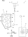
- FIG. 1 is a schematic diagram of a spun yarn take-up machine including an induction heating roller of the present embodiment.
- the spun yarn take-up machine 1 is configured to draw yarns Y serially spun out from a spinning apparatus 2 by a spun yarn drawing apparatus 3, and then to wind the yarns Y by a yarn winding apparatus 4.
- the spun yarn take-up machine 1 is configured to draw yarns Y serially spun out from a spinning apparatus 2 by a spun yarn drawing apparatus 3, and then to wind the yarns Y by a yarn winding apparatus 4.
- the spinning apparatus 2 is configured to generate the yarns Y by continuously spinning out a molten fibrous material such as polyester. To the yarns Y spun out from the spinning apparatus 2, oil is applied at an oil guide 10. The yarns Y are then sent to the spun yarn drawing apparatus 3 via a guide roller 11.
- the spun yarn drawing apparatus 3 is an apparatus for drawing the yarns Y and is provided below the spinning apparatus 2.
- the spun yarn drawing apparatus 3 includes plural godet rollers 21 to 25 housed in a thermal insulation box 12.
- the godet rollers 21 to 25 are induction heating rollers which are rotationally driven by a motor and are induction-heated by a coil.
- Yarns Y are wound onto the godet rollers 21 to 25.
- an inlet 12a is formed to introduce yarns Y into the thermal insulation box 12.
- an outlet 12b is formed to take yarns Y out from the thermal insulation box 12.
- the yarns Y are wound onto each of the godet rollers 21 to 25 at a winding angle of less than 360 degrees.
- the yarns Y are wound onto the godet rollers 21 to 25 in order, from the lowest godet roller 21.
- the lower three godet rollers 21 to 23 are preheating rollers for preliminarily heating the yarns Y before drawing them.
- the roller surface temperature of each of these rollers is arranged to be equal to or higher than the glass transition temperature of the yarns Y (e.g., set at about 90 to 100 degrees centigrade).
- the upper two godet rollers 24 and 25 are conditioning rollers for thermally setting the drawn yarns Y.
- the roller surface temperature of each of these rollers is arranged to be higher than the roller surface temperatures of the lower three godet rollers 21 to 23 (e.g., set at about 150 to 200 degrees centigrade).
- the yarn feeding speeds of the upper two godet rollers 24 and 25 are higher than those of the lower three godet rollers 21 to 23.
- the yarns Y introduced into the thermal insulation box 12 through the inlet 12a are, to begin with, preliminarily heated to a drawable temperature while being transferred by the godet rollers 21 to 23.
- the preliminarily-heated yarns Y are drawn on account of a difference in yarn feeding speed between the godet roller 23 and the godet roller 24.
- the yarns Y are then further heated while being transferred by the godet rollers 24 and 25, with the result that the drawn state is thermally set.
- the yarns Y having been drawn in this way go out from the thermal insulation box 12 through the outlet 12b.
- the yarns Y drawn by the spun yarn drawing apparatus 3 are sent to the yarn winding apparatus 4 via a guide roller 13.
- the yarn winding apparatus 4 is an apparatus for winding the yarns Y and is provided below the spun yarn drawing apparatus 3.
- the yarn winding apparatus 4 includes members such as a bobbin holder 14 and a contact roller 15.
- the bobbin holder 14 is cylindrical in shape and extends in the front-rear direction.
- the bobbin holder 14 is rotationally driven by an unillustrated motor.
- bobbins B are attached along the axial direction to be side by side. By rotating the bobbin holder 14, the yarn winding apparatus 4 simultaneously winds the yarns Y onto the bobbins B, so as to produce packages P.
- the contact roller 15 makes contact with the surfaces of the packages P to adjust the shape of each package P by applying a predetermined contact pressure to each package P.
- FIG. 2 is a cross section of the induction heating roller 30 of the present embodiment. At least one of the godet rollers 21 to 25 shown in FIG. 1 may be the induction heating roller 30 shown in FIG. 2 .
- a roller main body 31 of the induction heating roller 30 is cantilevered by a motor 50 which rotationally drives the roller main body 31.
- the motor 50 side in the axial direction will be referred to as a base end side, whereas the side opposite to the motor 50 side in the axial direction will be referred to as a leading end side.
- the induction heating roller 30 includes the cylindrical roller main body 31 and a cylindrical coil 32 provided inside the roller main body 31.
- the induction heating roller 30 is configured to heat an outer circumferential surface 31a (hereinafter, a roller surface 31a) of the roller main body 31 by induction heating using the coil 32, so as to heat the yarns Y wound on the roller surface 31a.
- the motor 50 is arranged such that an output shaft 53 of the motor 50 is rotatably supported by a bearing 52 of a housing 51.
- the roller main body 31 is made of, for example, carbon steel which is a magnetic body and a conductor.
- the roller main body 31 is arranged such that a cylindrical heating target 33, a cylindrical shaft center part 34, and a disc-shaped end face part 35 are integrally formed.
- the heating target 33 is provided radially outside the coil 32.
- the shaft center part 34 is provided radially inside the coil 32.
- the end face part 35 connects a leading end portion of the heating target 33 with a leading end portion of the shaft center part 34.
- a base end portion of the roller main body 31 is open, and the output shaft 53 of the motor 50 is inserted therein.
- the output shaft 53 is fixed to a shaft inserting hole 34a which is formed in the shaft center part 34. This arrangement allows the roller main body 31 and the output shaft 53 to rotate together.
- a cylindrical heat equalizer 36 is provided at a location which is radially inside the heating target 33 of the roller main body 31 and radially outside the coil 32.
- the heat equalizer 36 is made of a C/C composite (carbon fiber reinforced-carbon matrix-composite) which is a composite material of carbon fibers and graphite.
- the heat equalizer 36 has higher heat conductivity than the roller main body 31 and has a function of equalizing the temperature distribution of the heating target 33 in the axial direction.
- the outer diameter of the heat equalizer 36 is arranged to be substantially identical with the inner diameter of the heating target 33.
- the heat equalizer 36 is in contact with an inner circumferential surface 33a of the heating target 33. In the roller surface 31a, if an axially-extending region where the yarns Y are wound is a wound region R, the heat equalizer 36 is provided over a range including the wound region R in the axial direction.
- the heat equalizer 36 will be detailed later.
- the coil 32 is arranged such that conducting wires are wound onto a cylindrical bobbin member 38.
- the bobbin member 38 is, for example, attached to the housing 51 of the motor 50.
- a high-frequency current is supplied from an unillustrated power source to the coil 32, an eddy current is generated at the heating target 33 by alternating fluxes penetrating the heating target 33, with the result that the heating target 33 is induction-heated.
- the base end portion of the heating target 33 is covered with an annular cover member 39.
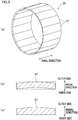
- FIG. 3(a) is a perspective view of the heat equalizer 36.
- FIG. 3(b) and FIG. 3(c) are cross sections of a heat equalization piece 37 constituting the heat equalizer 36, which are taken along a direction orthogonal to the axial direction.
- the heat equalizer 36 is cylindrical in overall shape as plural heat equalization pieces 37 extending in the axial direction are aligned in the circumferential direction.
- the radially outer surface of each heat equalization piece 37 is circular-arc-shaped in a cross section orthogonal to the axial direction.
- the radially inner surface of the heat equalization piece 37 is not required to have a specific shape.
- the surface may be circular-arc-shaped as shown in FIG. 3(b) , or may be linear as shown in FIG. 3(c) .
- the C/C composite of which the heat equalizer 36 is made is manufactured by laminating layers of carbon fibers together with a matrix material (base material) and baking the layers at a high pressure and temperature.
- the C/C composite is typically plate-shaped, and is not easily molded into a cylindrical shape.
- the heat equalization piece 37 is manufactured in such a way that a plate member which is rectangular in cross section is manufactured, and then parts of the plate member are cut off.
- FIG. 4 is a table of physical properties of the roller main body 31 and the heat equalizer 36.
- the orientations of the carbon fibers of the C/C composite are adjustable when manufactured.
- "ORIENTED IN AXIAL DIRECTION" in the table indicates that the carbon fibers are oriented in the axial direction
- "RANDOM ORIENTATION” indicates that the carbon fibers are not oriented in a particular direction.
- the heat conductivity is varied depending on the orientation of the carbon fibers.
- the heat equalizer 36 of the present embodiment equalizes the temperature distribution of the heating target 33 in the axial direction. It is therefore important to obtain high heat conductivity in the axial direction.
- the heat conductivity in the present invention is heat conductivity in the axial direction.
- a C/C composite in which carbon fibers are oriented in the axial direction or randomly is used.
- the C/C composite is suitable as a material of the heat equalizer 36 because of high heat conductivity and lightness in weight.
- the linear expansion coefficient is significantly low as compared to carbon steel.
- the roller main body 31 expands significantly more than the heat equalizer 36 in the induction heating, with the result that a gap is formed between the heating target 33 and the heat equalizer 36. Heat conduction between the heating target 33 and the heat equalizer 36 becomes hindered, and the heat equalization effect of the heat equalizer 36 is not sufficiently exerted.
- a pressing mechanism 40 (see FIG. 2 ) is provided to press the heat equalization pieces 37 constituting the heat equalizer 36 toward the inner circumferential surface 33a of the heating target 33, in order to keep each heat equalization piece 37 to be in contact with the heating target 33 in the induction heating.
- FIG. 5 is an enlarged cross section of the heat equalization piece 37 and the pressing mechanism 40 and their surroundings. Both end faces in the axial direction of the heat equalization piece 37 are tapered surfaces 37a and 37b which are inclined radially outward and axially outward. In the present embodiment, the tapered surfaces 37a and 37b are identical in inclination angle.
- the pressing mechanism 40 is provided on the base end side of the heat equalization piece 37.
- the pressing mechanism 40 includes an interposed member 41 adjacent to the base-end-side tapered surface 37a of the heat equalization piece 37 and a spring 42 which biases the interposed member 41 toward the leading end side.
- the interposed member 41 is an annular member extending in the circumferential direction of the roller main body 31.
- the interposed member 41 of the present embodiment is made of, for example, a ferrous material or a stainless streel material.
- the interposed member 41 includes a pressing surface 41a which is in contact with all heat equalization pieces 37 aligned in the circumferential direction.
- the pressing surface 41a is tapered to correspond to the shape of the tapered surface 37a.
- the interposed member 41 is sandwiched in the radial direction between the heating target 33 of the roller main body 31 and a regulatory portion 39a of a cover member 39.
- the spring 42 is provided on the base end side of the interposed member 41 and is housed in a concave portion 39b formed in the cover member 39.
- Springs 42 are provided at regular intervals in the circumferential direction. For example, one spring 42 may be provided for one heat equalization piece 37, plural springs 42 may be provided for one heat equalization piece 37, or one spring 42 may be provided for plural heat equalization pieces 37.
- an engaging surface 31b is formed to be tapered in accordance with the tapered surface 37b on the leading end side of the heat equalization piece 37.
- the heat equalization piece 37 is provided to be sandwiched between the interposed member 41 and the engaging surface 31b in the axial direction.
- the tapered surface 37a of the heat equalization piece 37 is pressed by the pressing surface 41a of the interposed member 41 toward the leading end side.
- This pressing force is converted to force which presses the heat equalization piece 37 radially outward by the tapered surface 37a.
- the tapered surface 37b of the heat equalization piece 37 is pressed toward the base end side by reaction force from the engaging surface 31b. This reaction force is also converted to force which presses the heat equalization piece 37 radially outward by the tapered surface 37b.
- the heat equalization piece 37 is pressed radially outward evenly in the axial direction (see arrows in FIG. 5 ).
- the contact state between the heating target 33 and the heat equalizer 36 is maintained as each heat equalization piece 37 is pressed onto the inner circumferential surface 33a of the heating target 33.
- the cylindrical heat equalizer 36 is constituted by plural heat equalization pieces 37, and each heat equalization piece 37 is pressed onto the inner circumferential surface 33a of the heating target 33 by the pressing mechanism 40. For this reason, even when the roller main body 31 expands significantly more than the heat equalizer 36 in induction heating, the contact state between each heat equalization piece 37 and the inner circumferential surface 33a of the heating target 33 is maintained. It is therefore possible to prevent the deterioration of the heat equalizing effect of the heat equalizer 36.
- the state in which the heat equalization piece 37 is in contact with the inner circumferential surface 33a of the heating target 33 may be maintained by, for example, adhering the heat equalization pieces 37 to the inner circumferential surface 33a of the heating target 33.
- the adhered part may be broken when relative displacement in the axial direction or the circumferential direction occurs due to a difference in expansion between the roller main body 31 and the heat equalizer 36.
- each heat equalization piece 37 is simply pressed toward the inner circumferential surface 33a of the heating target 33. The heat equalization pieces 37 are therefore allowed to be displaced in the axial direction and the circumferential direction relative to the heating target 33. The problem above does not therefore occur in the present embodiment.
- the coil 32 is provided radially inside the heating target 33, and the heating target 33 is induction-heated by the coil 32.
- the heating target 33 is induction-heated by the coil 32.
- the present invention which makes it possible to reliably maintain the heat equalizing effect of the heat equalizer 36 in induction heating is therefore effective for the heating roller 30.
- each heat equalization piece 37 is circular-arc-shaped in a cross section orthogonal to the axial direction. With this arrangement, the radially outer surface of the heat equalization piece 37 extends along the inner circumferential surface of the heating target 33 and hence the contact area between the heat equalization piece 37 and the heating target 33 is large. It is therefore possible to further improve the heat equalizing effect.
- the pressing mechanism 40 is provided outside the heat equalization pieces 37 in the axial direction.
- the pressing mechanism 40 is provided outside the heat equalization pieces 37 in the axial direction in this way, it is unnecessary to provide the pressing mechanism at a central portion of the roller main body 31, and hence it is possible to maintain a suitable rotation balance of the roller main body 31.
- the induction heating in addition to the above, the number of magnetic fluxes penetrating the pressing mechanism 40 can be reduced, and hence the heating efficiency of the roller main body 31 can be improved.
- At least one end face in the axial direction of the heat equalization piece 37 is the tapered surface 37a inclined radially outward and axially outward, and the pressing mechanism 40 presses the tapered surface 37a in the axial direction.
- the pressing mechanism 40 includes: the interposed member 41 which makes contact with the tapered surface 37a and has the pressing surface 41a tapered to correspond to the tapered surface 37a in shape; and the spring 42 (biasing member) which biases the interposed member 41 in the axial direction to press the tapered surface 37a in the axial direction by the pressing surface 41a. Because the interposed member 41 is provided between the spring 42 and the heat equalization piece 37, the tapered surface 37a is reliably pressed in the axial direction by the pressing surface 41a, and hence the heat equalization piece 37 is further effectively pressed toward the inner circumferential surface 33a of the heating target 33.
- the interposed member 41 is an annular member making contact with the tapered surface 37a of each heat equalization piece 37. Because it is unnecessary to provide an interposed member 41 for each heat equalization piece 37 and only one interposed member 41 is required, the arrangement is advantageous in terms of cost and assembling efficiency.
- the springs 42 are provided at regular intervals in the circumferential direction. With this arrangement, all heat equalization pieces 37 are evenly pressed by one interposed member 41. The heat equalization pieces 37 are therefore evenly pressed toward the inner circumferential surface 33a of the heating target 33.
- the tapered surfaces 37a and 37b are formed on the both sides of the heat equalization piece 37 in the axial direction
- the pressing mechanism 40 is provided only on one side of the heat equalization piece 37 in the axial direction
- the roller main body 31 has the engaging surface 31b which is tapered to correspond in shape to the tapered surface 37b of the heat equalization piece 37, which is the other tapered surface in the axial direction.
- the heat equalization piece 37 is evenly pressed radially outward, and the entire heat equalization piece 37 suitably makes contact with the inner circumferential surface 33a of the heating target 33. Furthermore, because the pressing mechanism 40 is provided only on one side of the heat equalization piece 37, the number of components is small.
- the roller main body 31 is cantilevered, and the pressing mechanism 40 is provided on the base end side in the axial direction, where the roller main body 31 is cantilevered. Because the roller main body 31 is cantilevered, parts of the leading end portion of the roller main body 31 exposed to the outside air are large as compared to the base end portion. For this reason, heat dissipation and temperature decrease are facilitated. For this reason, as the pressing mechanism 40 is provided on the base end side of the roller main body 31, it is possible to press the heat equalization piece 37 toward the leading end side and cause the heat equalization piece 37 to reliably make contact with the leading end portion of the roller main body 31. As a result, heat transfer to the leading end portion of the roller main body 31 via the heat equalization piece 37 is facilitated, temperature decrease at the leading end portion of the roller main body 31 is suppressed, and the heat equalizing effect is improved.
- the heat equalizer 36 is made of a C/C composite (carbon fiber composite).
- the carbon fiber composite is suitable for a material of the heat equalizer 36 on account of high heat conduction and lightness.
- the linear expansion coefficient of the carbon fiber composite is very small, and hence a gap tends to be formed between the roller main body 31 and the heat equalizer 36 when heated.
- the carbon fiber composite can be employed as a material of the heat equalizer 36.
- plural yarns Y are wound on the surface of the induction heating roller 30 to be aligned in the axial direction.
- the induction heating roller 30 prevents the heat equalizing effect of the heat equalizer 36 from being deteriorated as described above, with the result that the temperature distribution in the axial direction of the surface of the induction heating roller 30 is equalized. Differences in quality between the yarns Y wound on the induction heating roller 30 are therefore suppressed, and high-quality yarns Y are produced.
- the pressing mechanism 140 is formed of two annular ring members 141.
- Each ring member 141 is made of a material (e.g., aluminum alloy or copper alloy) having a higher linear expansion coefficient than the roller main body 31.
- the two ring members 141 are fitted to the inside of the respective end portions in the axial direction of the heat equalization piece 137 by cool fitting. As the cool-fitted ring members 141 expand at room temperatures, the heat equalization piece 137 is pressed toward the inner circumferential surface 33a of the heating target 33. For this reason, even when the roller main body 31 expands in induction heating, the contact state between each heat equalization piece 137 and the inner circumferential surface 33a of the heating target 33 is maintained.
- the number and locations of the ring members 141 are not limited to the above-mentioned number and locations in this modification, and may be suitably changed.
- the pressing mechanism 140 is very easily constructed.
- the efficiency of heating the heating target 33 of the roller main body 31 may be deteriorated on account of increase in number of magnetic fluxes penetrating the pressing mechanism 140 (ring members 141).
- the pressing mechanism 40 is provided axially outside the heat equalization piece 37 as in the embodiment above, the number of magnetic fluxes penetrating the pressing mechanism 40 is reduced, and hence the heating efficiency of the roller main body 31 is advantageously improved.
Landscapes
- Engineering & Computer Science (AREA)
- General Engineering & Computer Science (AREA)
- Physics & Mathematics (AREA)
- Electromagnetism (AREA)
- Mechanical Engineering (AREA)
- General Induction Heating (AREA)
- Yarns And Mechanical Finishing Of Yarns Or Ropes (AREA)
- Spinning Or Twisting Of Yarns (AREA)
Abstract
Description
- The present invention relates to a heating roller and a spun yarn drawing apparatus.
- For example, as shown in Patent Literature 1, an induction heating roller which is configured to heat a roller surface by induction heating using a coil has been known. In such an induction heating roller, it is difficult to arrange an amount of heat generated by the induction heating to be uniform in the axial direction, with the result that the temperature of the roller surface tends to be uneven in the axial direction. The induction heating roller of Patent Literature 1 is therefore arranged such that a jacket chamber in which a gas-liquid two-phase heating medium is enclosed extends in the axial direction at around a surface of a roller main body. Because this jacket chamber functions as a heat pipe, the temperature of the roller surface is equalized in the axial direction.
- [Patent Literature 1] Japanese Laid-Open Patent Publication No.
2003-100437 - In the arrangement in which the heat pipe (jacket chamber) is provided in the roller main body as in Patent Literature 1, the roller main body is required to be thick in order to accommodate the heat pipe therein. As a result, the heat capacity of the roller main body is large and hence the roller surface cannot be effectively heated.
- Under this circumstance, the inventors of the subject application provided a cylindrical heat equalizer having higher heat conduction than the roller main body to be in contact with an inner circumferential surface of a heating target. Because the heat equalizer in contact with the roller main body functions as a heat pipe, the temperature distribution in the axial direction of the roller surface is equalized. Furthermore, because the heat equalizer is cylindrical, it is unnecessary to provide a structure for supporting the heat equalizer radially inside the heat equalizer. It is therefore possible to reduce the thickness of the roller main body. As a result, the roller surface is efficiently heated. Such a cylindrical heat equalizer is effective not only for the induction heating roller but also for heating rollers heated by other heating methods.
- A material of the heat equalizer is, for example, a carbon fiber composite which excels in heat conduction and lightness. The linear expansion coefficient of the carbon fiber composite, however, is very small. For this reason, the roller main body expands significantly more than the heat equalizer in the induction heating, with the result that a gap is formed between the roller main body and the heat equalizer. Heat conduction between the roller main body and the heat equalizer becomes hindered, and the heat equalization effect of the heat equalizer is not sufficiently exerted.
- In order to solve the problem above, an object of a heating roller of the present invention is to prevent deterioration of a heat equalizing effect of a heat equalizer due to a gap formed by a thermal expansion difference, when the cylindrical heat equalizer which is higher in thermal conductivity than and lower in linear expansion coefficient than a roller main body is provided in the heating roller.
- A heating roller of the present invention includes: a roller main body which includes a cylindrical heating target; and a cylindrical heat equalizer which is provided to be in contact with an inner circumferential surface of the heating target, the heat equalizer being higher in heat conductivity than and lower in linear expansion coefficient than the roller main body, heat equalization pieces each extending in an axial direction being lined up in a circumferential direction so as to form the cylindrical heat equalizer, and the heating roller further including a pressing mechanism which is configured to press each of the heat equalization pieces toward the inner circumferential surface of the heating target.
- In the present invention, the cylindrical heat equalizer is constituted by plural heat equalization pieces, and each heat equalization piece is pressed onto the inner circumferential surface of the heating target by the pressing mechanism. For this reason, even when the roller main body expands significantly more than the heat equalizer in induction heating, the contact state between each heat equalization piece and the inner circumferential surface of the heating target is maintained. It is therefore possible to prevent the deterioration of the heat equalizing effect of the heat equalizer. In this connection, the state in which the heat equalization piece is in contact with the inner circumferential surface of the heating target may be maintained by, for example, adhering the heat equalization pieces to the inner circumferential surface of the heating target. However, in this case, the adhered part may be broken when relative displacement in the axial direction or the circumferential direction occurs due to a difference in expansion between the roller main body and the heat equalizer. In this regard, in the present invention, each heat equalization piece is simply pressed toward the inner circumferential surface of the heating target. The heat equalization pieces are therefore allowed to be displaced in the axial direction and the circumferential direction relative to the heating target. The problem above does not therefore occur in the present embodiment.
- The present invention is preferably arranged such that a coil which is provided radially inside the heating target is further included, and the heating target being induction-heated by the coil.
- In such an induction-heated heating roller, it is particularly difficult to equalize the temperature distribution of the heating target in the axial direction. The present invention which makes it possible to reliably maintain the heat equalizing effect of the heat equalizer in induction heating is therefore effective for the heating roller.
- The present invention is preferably arranged such that each of the heat equalization pieces has a radially outer surface which is circular-arc-shaped in a cross section orthogonal to the axial direction.
- With this arrangement, the radially outer surface of the heat equalization piece extends along the inner circumferential surface of the heating target and hence the contact area between the heat equalization piece and the heating target is large. It is therefore possible to further improve the heat equalizing effect.
- The present invention is preferably arranged such that the pressing mechanism is provided outside the heat equalization pieces in the axial direction.
- When the pressing mechanism is provided outside the heat equalization pieces in the axial direction in this way, it is unnecessary to provide the pressing mechanism at a central portion of the roller main body, and hence it is possible to maintain a suitable rotation balance of the roller main body. In the induction heating, in addition to the above, the number of magnetic fluxes penetrating the pressing mechanism can be reduced, and hence the heating efficiency of the roller main body can be improved.
- The present invention is preferably arranged such that at least one end face in the axial direction of each of the heat equalization pieces is a tapered surface which is inclined radially outward and axially outward, and, the pressing mechanism presses the tapered surface in the axial direction.
- With this arrangement, as the pressing mechanism presses the tapered surface of the heat equalization piece in the axial direction, the heat equalization piece is pressed radially outward, i.e., toward the inner circumferential surface of the heating target. For this reason, even when the pressing mechanism is provided outside the heat equalization pieces in the axial direction, the heat equalization pieces are pressed toward the inner circumferential surface of the heating target, with a simple arrangement.
- The present invention is preferably arranged such that the pressing mechanism includes: an interposed member which has a pressing surface making contact with the tapered surface and tapered to correspond to the tapered surface in shape; and at least one biasing member which is configured to bias the interposed member in the axial direction to press the tapered surface in the axial direction by the pressing surface.
- Because the interposed member is provided between the biasing member and the heat equalization piece, the tapered surface is reliably pressed in the axial direction by the pressing surface, and hence the heat equalization piece is further effectively pressed toward the inner circumferential surface of the heating target.
- The present invention is preferably arranged such that the interposed member is an annular member which makes contact with the tapered surface of each of the heat equalization pieces.
- Because it is unnecessary to provide an interposed member for each heat equalization piece and only one interposed member is required, the arrangement is advantageous in terms of cost and assembling efficiency.
- The present invention is preferably arranged such that the biasing members are provided at regular intervals in the circumferential direction.
- With this arrangement, all heat equalization pieces are evenly pressed by one interposed member. The heat equalization pieces are therefore evenly pressed toward the inner circumferential surface of the heating target.
- The present invention is preferably arranged such that both end surfaces in the axial direction of each of the heat equalization pieces are tapered surfaces, the pressing mechanism is provided only on one side of each of the heat equalization pieces in the axial direction, and the roller main body has an engaging surface which is tapered to correspond in shape to the tapered surface on the other side of each of the heat equalization pieces in the axial direction.
- With this arrangement, one tapered surface of the heat equalization piece is pressed by the pressing mechanism whereas the other tapered surface is pressed by reaction force from the engaging surface. As such, the heat equalization piece is evenly pressed radially outward, and the entire heat equalization piece suitably makes contact with the inner circumferential surface of the heating target. Furthermore, because the pressing mechanism is provided only on one side of the heat equalization piece, the number of components is small.
- The present invention is preferably arranged such that the roller main body is cantilevered, and the pressing mechanism is provided on a base end side of the roller main body in the axial direction.
- Because the roller main body is cantilevered, parts of the leading end portion of the roller main body exposed to the outside air are large as compared to the base end portion. For this reason, heat dissipation and temperature decrease are facilitated. For this reason, as the pressing mechanism is provided on the base end side of the roller main body, it is possible to press the heat equalization piece toward the leading end side and cause the heat equalization piece to reliably make contact with the leading end portion of the roller main body. As a result, heat transfer to the leading end portion of the roller main body via the heat equalization piece is facilitated, temperature decrease at the leading end portion of the roller main body is suppressed, and the heat equalizing effect is improved.
- The present invention is preferably arranged such that the heat equalizer is made of a carbon fiber composite.
- The carbon fiber composite is suitable for a material of the heat equalizer on account of high heat conduction and lightness. However, the linear expansion coefficient of the carbon fiber composite is very small, and hence a gap tends to be formed between the roller main body and the heat equalizer when heated. In the present invention, because such a gap is eliminated by the pressing mechanism, the carbon fiber composite can be employed as a material of the heat equalizer.
- A spun yarn drawing apparatus of the present invention includes any one of the above-described heating rollers, yarns being wound on a surface of the heating roller to be aligned in the axial direction.
- The heating roller of the present invention prevents the heat equalizing effect of the heat equalizer from being deteriorated as described above, with the result that the temperature distribution in the axial direction of the surface of the heating roller is equalized. Differences in quality between the yarns wound on the heating roller are therefore suppressed, and high-quality yarns are produced.
-
-
FIG. 1 is a schematic diagram of a spun yarn take-up machine including an induction heating roller of an embodiment. -
FIG. 2 is a cross section of the induction heating roller of the embodiment. -
FIG. 3(a) is a perspective view of a heat equalizer.FIG. 3(b) and FIG. 3(c) are cross sections of a heat equalization piece. -
FIG. 4 is a table of physical properties of the roller main body and the heat equalizer. -
FIG. 5 is an enlarged cross section of the heat equalization piece and a pressing mechanism and their surroundings. -
FIG. 6 is a cross section of an induction heating roller of a modification. - The following will describe an embodiment of the present invention.
FIG. 1 is a schematic diagram of a spun yarn take-up machine including an induction heating roller of the present embodiment. As shown inFIG. 1 , the spun yarn take-up machine 1 is configured to draw yarns Y serially spun out from aspinning apparatus 2 by a spunyarn drawing apparatus 3, and then to wind the yarns Y by ayarn winding apparatus 4. Hereinafter, explanations will be given with reference to the directions shown in the figures. - The
spinning apparatus 2 is configured to generate the yarns Y by continuously spinning out a molten fibrous material such as polyester. To the yarns Y spun out from thespinning apparatus 2, oil is applied at anoil guide 10. The yarns Y are then sent to the spunyarn drawing apparatus 3 via a guide roller 11. - The spun
yarn drawing apparatus 3 is an apparatus for drawing the yarns Y and is provided below thespinning apparatus 2. The spunyarn drawing apparatus 3 includesplural godet rollers 21 to 25 housed in athermal insulation box 12. Thegodet rollers 21 to 25 are induction heating rollers which are rotationally driven by a motor and are induction-heated by a coil. Yarns Y are wound onto thegodet rollers 21 to 25. At a lower part of a right side portion of thethermal insulation box 12, aninlet 12a is formed to introduce yarns Y into thethermal insulation box 12. At an upper part of the right side portion of thethermal insulation box 12, anoutlet 12b is formed to take yarns Y out from thethermal insulation box 12. The yarns Y are wound onto each of thegodet rollers 21 to 25 at a winding angle of less than 360 degrees. The yarns Y are wound onto thegodet rollers 21 to 25 in order, from thelowest godet roller 21. - The lower three
godet rollers 21 to 23 are preheating rollers for preliminarily heating the yarns Y before drawing them. The roller surface temperature of each of these rollers is arranged to be equal to or higher than the glass transition temperature of the yarns Y (e.g., set at about 90 to 100 degrees centigrade). Meanwhile, the upper twogodet rollers godet rollers 21 to 23 (e.g., set at about 150 to 200 degrees centigrade). The yarn feeding speeds of the upper twogodet rollers godet rollers 21 to 23. - The yarns Y introduced into the
thermal insulation box 12 through theinlet 12a are, to begin with, preliminarily heated to a drawable temperature while being transferred by thegodet rollers 21 to 23. The preliminarily-heated yarns Y are drawn on account of a difference in yarn feeding speed between thegodet roller 23 and thegodet roller 24. The yarns Y are then further heated while being transferred by thegodet rollers thermal insulation box 12 through theoutlet 12b. - The yarns Y drawn by the spun
yarn drawing apparatus 3 are sent to theyarn winding apparatus 4 via aguide roller 13. Theyarn winding apparatus 4 is an apparatus for winding the yarns Y and is provided below the spunyarn drawing apparatus 3. Theyarn winding apparatus 4 includes members such as abobbin holder 14 and acontact roller 15. Thebobbin holder 14 is cylindrical in shape and extends in the front-rear direction. Thebobbin holder 14 is rotationally driven by an unillustrated motor. To thebobbin holder 14, bobbins B are attached along the axial direction to be side by side. By rotating thebobbin holder 14, theyarn winding apparatus 4 simultaneously winds the yarns Y onto the bobbins B, so as to produce packages P. Thecontact roller 15 makes contact with the surfaces of the packages P to adjust the shape of each package P by applying a predetermined contact pressure to each package P. -
FIG. 2 is a cross section of theinduction heating roller 30 of the present embodiment. At least one of thegodet rollers 21 to 25 shown inFIG. 1 may be theinduction heating roller 30 shown inFIG. 2 . A rollermain body 31 of theinduction heating roller 30 is cantilevered by amotor 50 which rotationally drives the rollermain body 31. Hereinafter, themotor 50 side in the axial direction will be referred to as a base end side, whereas the side opposite to themotor 50 side in the axial direction will be referred to as a leading end side. - The
induction heating roller 30 includes the cylindrical rollermain body 31 and acylindrical coil 32 provided inside the rollermain body 31. Theinduction heating roller 30 is configured to heat an outercircumferential surface 31a (hereinafter, aroller surface 31a) of the rollermain body 31 by induction heating using thecoil 32, so as to heat the yarns Y wound on theroller surface 31a. Meanwhile, themotor 50 is arranged such that anoutput shaft 53 of themotor 50 is rotatably supported by a bearing 52 of ahousing 51. - The roller
main body 31 is made of, for example, carbon steel which is a magnetic body and a conductor. The rollermain body 31 is arranged such that acylindrical heating target 33, a cylindricalshaft center part 34, and a disc-shaped end facepart 35 are integrally formed. Theheating target 33 is provided radially outside thecoil 32. Theshaft center part 34 is provided radially inside thecoil 32. The end facepart 35 connects a leading end portion of theheating target 33 with a leading end portion of theshaft center part 34. A base end portion of the rollermain body 31 is open, and theoutput shaft 53 of themotor 50 is inserted therein. Theoutput shaft 53 is fixed to ashaft inserting hole 34a which is formed in theshaft center part 34. This arrangement allows the rollermain body 31 and theoutput shaft 53 to rotate together. - A
cylindrical heat equalizer 36 is provided at a location which is radially inside theheating target 33 of the rollermain body 31 and radially outside thecoil 32. Theheat equalizer 36 is made of a C/C composite (carbon fiber reinforced-carbon matrix-composite) which is a composite material of carbon fibers and graphite. Theheat equalizer 36 has higher heat conductivity than the rollermain body 31 and has a function of equalizing the temperature distribution of theheating target 33 in the axial direction. The outer diameter of theheat equalizer 36 is arranged to be substantially identical with the inner diameter of theheating target 33. Theheat equalizer 36 is in contact with an innercircumferential surface 33a of theheating target 33. In theroller surface 31a, if an axially-extending region where the yarns Y are wound is a wound region R, theheat equalizer 36 is provided over a range including the wound region R in the axial direction. Theheat equalizer 36 will be detailed later. - The
coil 32 is arranged such that conducting wires are wound onto acylindrical bobbin member 38. Thebobbin member 38 is, for example, attached to thehousing 51 of themotor 50. When a high-frequency current is supplied from an unillustrated power source to thecoil 32, an eddy current is generated at theheating target 33 by alternating fluxes penetrating theheating target 33, with the result that theheating target 33 is induction-heated. The base end portion of theheating target 33 is covered with anannular cover member 39. - The
heat equalizer 36 is detailed below.FIG. 3(a) is a perspective view of theheat equalizer 36.FIG. 3(b) and FIG. 3(c) are cross sections of aheat equalization piece 37 constituting theheat equalizer 36, which are taken along a direction orthogonal to the axial direction. As shown inFIG. 3(a) , theheat equalizer 36 is cylindrical in overall shape as pluralheat equalization pieces 37 extending in the axial direction are aligned in the circumferential direction. As shown inFIG. 3(b) and FIG. 3(c) , the radially outer surface of eachheat equalization piece 37 is circular-arc-shaped in a cross section orthogonal to the axial direction. The radially inner surface of theheat equalization piece 37 is not required to have a specific shape. For example, the surface may be circular-arc-shaped as shown inFIG. 3(b) , or may be linear as shown inFIG. 3(c) . - The C/C composite of which the
heat equalizer 36 is made is manufactured by laminating layers of carbon fibers together with a matrix material (base material) and baking the layers at a high pressure and temperature. On this account, the C/C composite is typically plate-shaped, and is not easily molded into a cylindrical shape. For this reason, in the present embodiment, as indicated by dashed lines inFIG. 3(b) and FIG. 3(c) , theheat equalization piece 37 is manufactured in such a way that a plate member which is rectangular in cross section is manufactured, and then parts of the plate member are cut off. -
FIG. 4 is a table of physical properties of the rollermain body 31 and theheat equalizer 36. The orientations of the carbon fibers of the C/C composite are adjustable when manufactured. "ORIENTED IN AXIAL DIRECTION" in the table indicates that the carbon fibers are oriented in the axial direction, whereas "RANDOM ORIENTATION" indicates that the carbon fibers are not oriented in a particular direction. The heat conductivity is varied depending on the orientation of the carbon fibers. As described above, theheat equalizer 36 of the present embodiment equalizes the temperature distribution of theheating target 33 in the axial direction. It is therefore important to obtain high heat conductivity in the axial direction. For this reason, when the thermal conductivity of the heat equalizer is anisotropic, the heat conductivity in the present invention is heat conductivity in the axial direction. In the present embodiment, a C/C composite in which carbon fibers are oriented in the axial direction or randomly is used. - As clearly shown in
FIG. 4 , the C/C composite is suitable as a material of theheat equalizer 36 because of high heat conductivity and lightness in weight. However, the linear expansion coefficient is significantly low as compared to carbon steel. For this reason, the rollermain body 31 expands significantly more than theheat equalizer 36 in the induction heating, with the result that a gap is formed between theheating target 33 and theheat equalizer 36. Heat conduction between theheating target 33 and theheat equalizer 36 becomes hindered, and the heat equalization effect of theheat equalizer 36 is not sufficiently exerted. To solve this problem, in the present embodiment, a pressing mechanism 40 (seeFIG. 2 ) is provided to press theheat equalization pieces 37 constituting theheat equalizer 36 toward the innercircumferential surface 33a of theheating target 33, in order to keep eachheat equalization piece 37 to be in contact with theheating target 33 in the induction heating. - The
pressing mechanism 40 will be detailed with reference toFIG. 5. FIG. 5 is an enlarged cross section of theheat equalization piece 37 and thepressing mechanism 40 and their surroundings. Both end faces in the axial direction of theheat equalization piece 37 are taperedsurfaces tapered surfaces - The
pressing mechanism 40 is provided on the base end side of theheat equalization piece 37. Thepressing mechanism 40 includes an interposedmember 41 adjacent to the base-end-side taperedsurface 37a of theheat equalization piece 37 and aspring 42 which biases the interposedmember 41 toward the leading end side. The interposedmember 41 is an annular member extending in the circumferential direction of the rollermain body 31. The interposedmember 41 of the present embodiment is made of, for example, a ferrous material or a stainless streel material. The interposedmember 41 includes apressing surface 41a which is in contact with allheat equalization pieces 37 aligned in the circumferential direction. Thepressing surface 41a is tapered to correspond to the shape of the taperedsurface 37a. The interposedmember 41 is sandwiched in the radial direction between theheating target 33 of the rollermain body 31 and aregulatory portion 39a of acover member 39. Thespring 42 is provided on the base end side of the interposedmember 41 and is housed in aconcave portion 39b formed in thecover member 39.Springs 42 are provided at regular intervals in the circumferential direction. For example, onespring 42 may be provided for oneheat equalization piece 37, plural springs 42 may be provided for oneheat equalization piece 37, or onespring 42 may be provided for pluralheat equalization pieces 37. - At an inner surface of the end face
part 35 of the roller main body 31 (i.e., a part of the inner surface of the end facepart 35 at around a corner portion formed between the end facepart 35 and the heating target 33), anengaging surface 31b is formed to be tapered in accordance with thetapered surface 37b on the leading end side of theheat equalization piece 37. Theheat equalization piece 37 is provided to be sandwiched between the interposedmember 41 and theengaging surface 31b in the axial direction. - As the
spring 42 biases the interposedmember 41 toward the leading end side, thetapered surface 37a of theheat equalization piece 37 is pressed by thepressing surface 41a of the interposedmember 41 toward the leading end side. This pressing force is converted to force which presses theheat equalization piece 37 radially outward by the taperedsurface 37a. Furthermore, thetapered surface 37b of theheat equalization piece 37 is pressed toward the base end side by reaction force from theengaging surface 31b. This reaction force is also converted to force which presses theheat equalization piece 37 radially outward by the taperedsurface 37b. - As such, as the
tapered surfaces heat equalization piece 37 are pressed axially inward, theheat equalization piece 37 is pressed radially outward evenly in the axial direction (see arrows inFIG. 5 ). With this arrangement, even when the rollermain body 31 expands significantly more than theheat equalizer 36 in induction heating, the contact state between theheating target 33 and theheat equalizer 36 is maintained as eachheat equalization piece 37 is pressed onto the innercircumferential surface 33a of theheating target 33. - In the induction heating roller 30 (equivalent to a heating roller of the present invention) of the present embodiment, the
cylindrical heat equalizer 36 is constituted by pluralheat equalization pieces 37, and eachheat equalization piece 37 is pressed onto the innercircumferential surface 33a of theheating target 33 by thepressing mechanism 40. For this reason, even when the rollermain body 31 expands significantly more than theheat equalizer 36 in induction heating, the contact state between eachheat equalization piece 37 and the innercircumferential surface 33a of theheating target 33 is maintained. It is therefore possible to prevent the deterioration of the heat equalizing effect of theheat equalizer 36. In this connection, the state in which theheat equalization piece 37 is in contact with the innercircumferential surface 33a of theheating target 33 may be maintained by, for example, adhering theheat equalization pieces 37 to the innercircumferential surface 33a of theheating target 33. However, in this case, the adhered part may be broken when relative displacement in the axial direction or the circumferential direction occurs due to a difference in expansion between the rollermain body 31 and theheat equalizer 36. In this regard, in the present embodiment, eachheat equalization piece 37 is simply pressed toward the innercircumferential surface 33a of theheating target 33. Theheat equalization pieces 37 are therefore allowed to be displaced in the axial direction and the circumferential direction relative to theheating target 33. The problem above does not therefore occur in the present embodiment. - In the present embodiment, the
coil 32 is provided radially inside theheating target 33, and theheating target 33 is induction-heated by thecoil 32. In such an induction-heated heating roller 30, it is particularly difficult to equalize the temperature distribution of theheating target 33 in the axial direction. The present invention which makes it possible to reliably maintain the heat equalizing effect of theheat equalizer 36 in induction heating is therefore effective for theheating roller 30. - In the present embodiment, the radially outer surface of each
heat equalization piece 37 is circular-arc-shaped in a cross section orthogonal to the axial direction. With this arrangement, the radially outer surface of theheat equalization piece 37 extends along the inner circumferential surface of theheating target 33 and hence the contact area between theheat equalization piece 37 and theheating target 33 is large. It is therefore possible to further improve the heat equalizing effect. - In the present embodiment, the
pressing mechanism 40 is provided outside theheat equalization pieces 37 in the axial direction. When thepressing mechanism 40 is provided outside theheat equalization pieces 37 in the axial direction in this way, it is unnecessary to provide the pressing mechanism at a central portion of the rollermain body 31, and hence it is possible to maintain a suitable rotation balance of the rollermain body 31. In the induction heating, in addition to the above, the number of magnetic fluxes penetrating thepressing mechanism 40 can be reduced, and hence the heating efficiency of the rollermain body 31 can be improved. - In the present embodiment, at least one end face in the axial direction of the
heat equalization piece 37 is the taperedsurface 37a inclined radially outward and axially outward, and thepressing mechanism 40 presses thetapered surface 37a in the axial direction. With this arrangement, as thepressing mechanism 40 presses thetapered surface 37a of theheat equalization piece 37 in the axial direction, theheat equalization piece 37 is pressed radially outward, i.e., toward the innercircumferential surface 33a of theheating target 33. For this reason, even when thepressing mechanism 40 is provided outside theheat equalization pieces 37 in the axial direction, theheat equalization pieces 37 are pressed toward the innercircumferential surface 33a of theheating target 33, with a simple arrangement. - In the present embodiment, the
pressing mechanism 40 includes: the interposedmember 41 which makes contact with thetapered surface 37a and has thepressing surface 41a tapered to correspond to the taperedsurface 37a in shape; and the spring 42 (biasing member) which biases the interposedmember 41 in the axial direction to press the taperedsurface 37a in the axial direction by thepressing surface 41a. Because the interposedmember 41 is provided between thespring 42 and theheat equalization piece 37, thetapered surface 37a is reliably pressed in the axial direction by thepressing surface 41a, and hence theheat equalization piece 37 is further effectively pressed toward the innercircumferential surface 33a of theheating target 33. - In the present embodiment, the interposed
member 41 is an annular member making contact with thetapered surface 37a of eachheat equalization piece 37. Because it is unnecessary to provide an interposedmember 41 for eachheat equalization piece 37 and only one interposedmember 41 is required, the arrangement is advantageous in terms of cost and assembling efficiency. - In the present embodiment, the
springs 42 are provided at regular intervals in the circumferential direction. With this arrangement, allheat equalization pieces 37 are evenly pressed by one interposedmember 41. Theheat equalization pieces 37 are therefore evenly pressed toward the innercircumferential surface 33a of theheating target 33. - In the present embodiment, the
tapered surfaces heat equalization piece 37 in the axial direction, thepressing mechanism 40 is provided only on one side of theheat equalization piece 37 in the axial direction, and the rollermain body 31 has theengaging surface 31b which is tapered to correspond in shape to the taperedsurface 37b of theheat equalization piece 37, which is the other tapered surface in the axial direction. With this arrangement, one taperedsurface 37a of theheat equalization piece 37 is pressed by thepressing mechanism 40 whereas the othertapered surface 37b is pressed by reaction force from theengaging surface 31b. As such, theheat equalization piece 37 is evenly pressed radially outward, and the entireheat equalization piece 37 suitably makes contact with the innercircumferential surface 33a of theheating target 33. Furthermore, because thepressing mechanism 40 is provided only on one side of theheat equalization piece 37, the number of components is small. - In the present embodiment, the roller
main body 31 is cantilevered, and thepressing mechanism 40 is provided on the base end side in the axial direction, where the rollermain body 31 is cantilevered. Because the rollermain body 31 is cantilevered, parts of the leading end portion of the rollermain body 31 exposed to the outside air are large as compared to the base end portion. For this reason, heat dissipation and temperature decrease are facilitated. For this reason, as thepressing mechanism 40 is provided on the base end side of the rollermain body 31, it is possible to press theheat equalization piece 37 toward the leading end side and cause theheat equalization piece 37 to reliably make contact with the leading end portion of the rollermain body 31. As a result, heat transfer to the leading end portion of the rollermain body 31 via theheat equalization piece 37 is facilitated, temperature decrease at the leading end portion of the rollermain body 31 is suppressed, and the heat equalizing effect is improved. - In the present embodiment, the
heat equalizer 36 is made of a C/C composite (carbon fiber composite). The carbon fiber composite is suitable for a material of theheat equalizer 36 on account of high heat conduction and lightness. However, the linear expansion coefficient of the carbon fiber composite is very small, and hence a gap tends to be formed between the rollermain body 31 and theheat equalizer 36 when heated. With the present embodiment, because such a gap is eliminated by thepressing mechanism 40, the carbon fiber composite can be employed as a material of theheat equalizer 36. - In the present embodiment, plural yarns Y are wound on the surface of the
induction heating roller 30 to be aligned in the axial direction. Theinduction heating roller 30 prevents the heat equalizing effect of theheat equalizer 36 from being deteriorated as described above, with the result that the temperature distribution in the axial direction of the surface of theinduction heating roller 30 is equalized. Differences in quality between the yarns Y wound on theinduction heating roller 30 are therefore suppressed, and high-quality yarns Y are produced. - The following will describe modifications of the above-described embodiment.
- (1) In the embodiment above, the heating roller of the present invention is applied to the
induction heating roller 30. The present invention, however, is applicable to those other than induction heating rollers. - (2) While in the embodiment above the
pressing mechanism 40 is provided axially outside theheat equalization pieces 37, apressing mechanism 140 may be provided radially insideheat equalization pieces 137, as shown inFIG. 6. FIG. 6 is a cross section of aninduction heating roller 130 of a modification. Among components of theinduction heating roller 130, components having the same structures as those in theinduction heating roller 30 of the above-described embodiment are given the same reference numerals, and descriptions thereof are omitted. Being different from theheat equalization pieces 37, end faces in the axial direction of each of theheat equalization pieces 137 constituting aheat equalizer 136 are not tapered surfaces. - The
pressing mechanism 140 is formed of twoannular ring members 141. Eachring member 141 is made of a material (e.g., aluminum alloy or copper alloy) having a higher linear expansion coefficient than the rollermain body 31. The tworing members 141 are fitted to the inside of the respective end portions in the axial direction of theheat equalization piece 137 by cool fitting. As the cool-fittedring members 141 expand at room temperatures, theheat equalization piece 137 is pressed toward the innercircumferential surface 33a of theheating target 33. For this reason, even when the rollermain body 31 expands in induction heating, the contact state between eachheat equalization piece 137 and the innercircumferential surface 33a of theheating target 33 is maintained. The number and locations of thering members 141 are not limited to the above-mentioned number and locations in this modification, and may be suitably changed. - By the cool fitting of the
ring members 141, thepressing mechanism 140 is very easily constructed. However, when thepressing mechanism 140 is provided radially inside theheat equalization piece 137, the efficiency of heating theheating target 33 of the rollermain body 31 may be deteriorated on account of increase in number of magnetic fluxes penetrating the pressing mechanism 140 (ring members 141). In this regard, when thepressing mechanism 40 is provided axially outside theheat equalization piece 37 as in the embodiment above, the number of magnetic fluxes penetrating thepressing mechanism 40 is reduced, and hence the heating efficiency of the rollermain body 31 is advantageously improved. - (3) In the embodiment above, the
pressing mechanism 40 is constituted by the interposedmember 41 and thespring 42. Alternatively, the interposedmember 41 may be omitted. Theheat equalization piece 37 is pressed toward the innercircumferential surface 33a of theheating target 33 even when theheat equalization piece 37 is biased toward the leading end side directly by thespring 42, on account of reaction force from theengaging surface 31b to the taperedsurface 37b on the leading end side. Alternatively, when the interposedmember 41 is made of a material (e.g., aluminum alloy or copper alloy) having higher linear expansion coefficient than the heating target 33 (roller main body 31) and the heat equalization piece 37 (heat equalizer 36), thespring 42 may be omitted. In this case, thetapered surface 37a of theheat equalization piece 37 is pressed by the interposedmember 41 which thermally expands. - (4) In the embodiment above, the end faces in the axial direction of the
heat equalization piece 37 are taperedsurfaces heat equalization piece 37 is a tapered surface, the other end face may not be a tapered surface. - (5) In the embodiment above, the
pressing mechanism 40 is provided only on one side of theheat equalization piece 37 in the axial direction. Alternatively, pressingmechanisms 40 may be provided on both sides of theheat equalization piece 37. - (6) In the embodiment above, the radially outer surface of the
heat equalization piece 37 is circular-arc-shaped. In this connection, when, for example, eachheat equalization piece 37 is narrow in the circumferential direction, theheat equalization pieces 37 can be arranged more or less along the inner circumferential surface of theheating target 33, even if the radially outer surface of eachheat equalization piece 37 is not circular-arc-shaped. - (7) While in the embodiment above the roller
main body 31 is made of carbon steel whereas theheat equalizer 36 is made of a C/C composite, the materials of these members are not limited to them. For example, the rollermain body 31 may be made of aluminum or copper. Furthermore, theheat equalizer 36 may be made of CFRP (carbon fiber reinforced plastic) which is a composite material of carbon fibers and resin (e.g., epoxy resin), instead of the C/C composite. Furthermore, theheat equalizer 36 may be made of a metal sintered material which is higher in heat conductivity than and lower in linear expansion coefficient than the rollermain body 31. It is usually difficult to mold a sintered material into a cylindrical shape. However, theheat equalizer 36 may be made of a sintered material when theheat equalizer 36 is constituted by pluralheat equalization pieces 37 as in the embodiment above. - (8) In the embodiment above, the roller
main body 31 is cantilevered. Alternatively, the rollermain body 31 may be supported on both sides. - (9) In the embodiment above, because plural yarns Y are wound on one
induction heating roller 30, differences in quality between the yarns Y are advantageously suppressed as the temperature distribution in the axial direction of theroller surface 31a is equalized. As a matter of course, the present invention is applicable to an induction heating roller on which a single yarn is wound. - (10) In the embodiment above, plural yarns Y are wound on one
induction heating roller 30 and the yarns Y are heated. In this regard, the use of theinduction heating roller 30 is not limited for heating the yarns Y. The roller may be used for heating materials other than the yarns Y, such as a film, paper, nonwoven fabric, a sheet such as a resin sheet, and a toner image on a sheet in a photocopier. -
- 30, 130:
- induction heating roller (heating roller)
- 31
- roller main body
- 32
- coil
- 33
- heating target
- 33a
- inner circumferential surface
- 36, 136
- heat equalizer
- 37 137
- heat equalization piece
- 37a, 37b
- tapered surface
- 40, 140
- pressing mechanism
- 41
- interposed member
- 41a
- pressing surface
- 42
- spring (biasing member)
Claims (12)
- A heating roller comprising:a roller main body which includes a cylindrical heating target; anda cylindrical heat equalizer which is provided to be in contact with an inner circumferential surface of the heating target, the heat equalizer being higher in heat conductivity than and lower in linear expansion coefficient than the roller main body,heat equalization pieces each extending in an axial direction being lined up in a circumferential direction so as to form the cylindrical heat equalizer, andthe heating roller further comprising a pressing mechanism which is configured to press each of the heat equalization pieces toward the inner circumferential surface of the heating target.
- The heating roller according to claim 1, further comprising a coil which is provided radially inside the heating target, the heating target being induction-heated by the coil.
- The heating roller according to claim 1 or 2, wherein, each of the heat equalization pieces has a radially outer surface which is circular-arc-shaped in a cross section orthogonal to the axial direction.
- The heating roller according to any one of claims 1 to 3, wherein, the pressing mechanism is provided outside the heat equalization pieces in the axial direction.
- The heating roller according to claim 4, wherein,
at least one end face in the axial direction of each of the heat equalization pieces is a tapered surface which is inclined radially outward and axially outward, and,
the pressing mechanism presses the tapered surface in the axial direction. - The heating roller according to claim 5, wherein, the pressing mechanism includes:an interposed member which has a pressing surface making contact with the tapered surface and tapered to correspond to the tapered surface in shape; andat least one biasing member which is configured to bias the interposed member in the axial direction to press the tapered surface in the axial direction by the pressing surface.
- The heating roller according to claim 6, wherein, the interposed member is an annular member which makes contact with the tapered surface of each of the heat equalization pieces.
- The heating roller according to claim 7, wherein, the biasing members are provided at regular intervals in the circumferential direction.
- The heating roller according to any one of claims 5 to 8, wherein,
both end surfaces in the axial direction of each of the heat equalization pieces are tapered surfaces,
the pressing mechanism is provided only on one side of each of the heat equalization pieces in the axial direction, and the roller main body has an engaging surface which is tapered to correspond in shape to the tapered surface on the other side of each of the heat equalization pieces in the axial direction. - The heating roller according to claim 9, wherein,
the roller main body is cantilevered, and
the pressing mechanism is provided on a base end side of the roller main body in the axial direction. - The heating roller according to any one of claims 1 to 10, wherein, the heat equalizer is made of a carbon fiber composite.
- A spun yarn drawing apparatus comprising the heating roller of any one of claims 1 to 11,
yarns being wound on a surface of the heating roller to be aligned in the axial direction.
Applications Claiming Priority (2)
| Application Number | Priority Date | Filing Date | Title |
|---|---|---|---|
| JP2017200810 | 2017-10-17 | ||
| PCT/JP2018/030735 WO2019077864A1 (en) | 2017-10-17 | 2018-08-21 | Induction heating roller and spun yarn drawing device |
Publications (3)
| Publication Number | Publication Date |
|---|---|
| EP3700301A1 true EP3700301A1 (en) | 2020-08-26 |
| EP3700301A4 EP3700301A4 (en) | 2021-07-14 |
| EP3700301B1 EP3700301B1 (en) | 2022-03-30 |
Family
ID=66174449
Family Applications (1)
| Application Number | Title | Priority Date | Filing Date |
|---|---|---|---|
| EP18868907.9A Active EP3700301B1 (en) | 2017-10-17 | 2018-08-21 | Induction heating roller and spun yarn drawing device |
Country Status (5)
| Country | Link |
|---|---|
| EP (1) | EP3700301B1 (en) |
| JP (1) | JP6857743B2 (en) |
| CN (1) | CN111133835B (en) |
| TW (1) | TWI750413B (en) |
| WO (1) | WO2019077864A1 (en) |
Families Citing this family (2)
| Publication number | Priority date | Publication date | Assignee | Title |
|---|---|---|---|---|
| JP7865718B2 (en) * | 2020-05-27 | 2026-05-26 | Tmtマシナリー株式会社 | Induction heating roller and spinning and drawing apparatus |
| CN113529217B (en) * | 2021-06-23 | 2022-05-17 | 无锡长江精密纺织有限公司 | Heatable drafting roller and ring spinning frame thereof |
Family Cites Families (26)
| Publication number | Priority date | Publication date | Assignee | Title |
|---|---|---|---|---|
| JPS4746141B1 (en) * | 1969-06-16 | 1972-11-02 | ||
| JPS4914827B1 (en) * | 1970-09-25 | 1974-04-10 | ||
| JPS5933476A (en) * | 1982-08-19 | 1984-02-23 | Matsushita Electric Ind Co Ltd | Fixation roll of copying machine |
| JPS60136375U (en) * | 1984-12-28 | 1985-09-10 | 特殊電機株式会社 | induction heating roller |
| EP0763667B1 (en) * | 1995-09-13 | 2001-12-19 | Idemitsu Petrochemical Co., Ltd. | Multi-layer structure roller and a method for producing the same |
| JPH09127810A (en) * | 1995-10-27 | 1997-05-16 | Minolta Co Ltd | Induction heating fixing device |
| JP3559716B2 (en) * | 1998-09-25 | 2004-09-02 | 株式会社リコー | Method for manufacturing induction heating type fixing device and induced current generating member thereof |
| JP2001126856A (en) * | 1999-10-26 | 2001-05-11 | Canon Inc | Induction heating device and image forming device |
| JP2002280158A (en) * | 2001-03-21 | 2002-09-27 | Ricoh Co Ltd | Induction heating roller |
| JP4903327B2 (en) * | 2001-09-21 | 2012-03-28 | トクデン株式会社 | Induction heating roller device |
| US7065315B2 (en) * | 2003-06-30 | 2006-06-20 | Kabushiki Kaisha Toshiba | Fixing apparatus |
| JP2005031308A (en) * | 2003-07-10 | 2005-02-03 | Toshiba Corp | Fixing device |
| JP4838992B2 (en) * | 2004-10-08 | 2011-12-14 | 古河スカイ株式会社 | Heater plate and heater plate manufacturing method |
| JP4749041B2 (en) * | 2005-06-09 | 2011-08-17 | トクデン株式会社 | Heat treatment roller device |
| DE102009029695A1 (en) * | 2009-09-23 | 2011-03-31 | Voith Patent Gmbh | roll cover |
| KR100958733B1 (en) * | 2009-11-10 | 2010-05-18 | 주식회사 모팜 | Multilayer roll forming sheet for a heat protector and manufacturing method thereof |
| TWM407828U (en) * | 2010-10-19 | 2011-07-21 | Prec Machinery Res & Dev Ct | External magnetic type electromagnetic heating roller for use in thin film solidification |
| JP5580242B2 (en) * | 2011-03-31 | 2014-08-27 | Tmtマシナリー株式会社 | Yarn heating device |
| EP2664428B1 (en) * | 2012-05-16 | 2016-03-23 | UHLMANN PAC-SYSTEME GmbH & Co. KG | Sealing roller |
| JP2015117447A (en) * | 2013-12-19 | 2015-06-25 | Tmtマシナリー株式会社 | Spinning pack, method for producing spinning pack, and method for modification of spinning pack |
| CN204046852U (en) * | 2014-08-29 | 2014-12-24 | 上海联净电子科技有限公司 | A kind of electromagnetic induction heating roller |
| CN204906751U (en) * | 2015-09-18 | 2015-12-23 | 徐仕坚 | Electromagnetic induction heating apparatus |
| CN204993918U (en) * | 2015-09-30 | 2016-01-20 | 杨开彬 | Annular heat pipe formula hot -rolling |
| CN205160821U (en) * | 2015-12-02 | 2016-04-13 | 乐道战略材料有限公司 | High -efficient electromagnetic heating roller |
| JP6909659B2 (en) * | 2016-08-25 | 2021-07-28 | Tmtマシナリー株式会社 | Induction heating roller |
| CN106429289B (en) * | 2016-12-19 | 2019-01-04 | 吕铁男 | A kind of hot type logistics roller |
-
2018
- 2018-08-21 JP JP2019549131A patent/JP6857743B2/en active Active
- 2018-08-21 WO PCT/JP2018/030735 patent/WO2019077864A1/en not_active Ceased
- 2018-08-21 CN CN201880061585.4A patent/CN111133835B/en active Active
- 2018-08-21 EP EP18868907.9A patent/EP3700301B1/en active Active
- 2018-09-17 TW TW107132572A patent/TWI750413B/en active
Also Published As
| Publication number | Publication date |
|---|---|
| WO2019077864A1 (en) | 2019-04-25 |
| JPWO2019077864A1 (en) | 2020-11-19 |
| EP3700301A4 (en) | 2021-07-14 |
| CN111133835B (en) | 2022-05-03 |
| EP3700301B1 (en) | 2022-03-30 |
| CN111133835A (en) | 2020-05-08 |
| TW201918115A (en) | 2019-05-01 |
| JP6857743B2 (en) | 2021-04-14 |
| TWI750413B (en) | 2021-12-21 |
Similar Documents
| Publication | Publication Date | Title |
|---|---|---|
| EP3288339B1 (en) | Induction heating roller | |
| EP3700301B1 (en) | Induction heating roller and spun yarn drawing device | |
| TW490517B (en) | Apparatus and method for cooling the bearings of a godet for advancing and guiding yarn | |
| JP7261854B2 (en) | Induction heating roller and spinning take-up machine | |
| JP4106277B2 (en) | Godet | |
| EP3700302B1 (en) | Induction heating roller and spun yarn drawing device | |
| CN102560798A (en) | A godet roller for guiding, heating and transporting filaments | |
| EP3700300B1 (en) | Induction heating roller and spun yarn drawing device | |
| EP3758445A1 (en) | Heating roller and spun yarn drawing device | |
| EP3917282A1 (en) | Induction heating roller and spun yarn drawing device | |
| JP7607907B2 (en) | Induction heating roller device | |
| JPH08270641A (en) | Heating roller device |
Legal Events
| Date | Code | Title | Description |
|---|---|---|---|
| STAA | Information on the status of an ep patent application or granted ep patent |
Free format text: STATUS: THE INTERNATIONAL PUBLICATION HAS BEEN MADE |
|
| PUAI | Public reference made under article 153(3) epc to a published international application that has entered the european phase |
Free format text: ORIGINAL CODE: 0009012 |
|
| STAA | Information on the status of an ep patent application or granted ep patent |
Free format text: STATUS: REQUEST FOR EXAMINATION WAS MADE |
|
| 17P | Request for examination filed |
Effective date: 20200326 |
|
| AK | Designated contracting states |
Kind code of ref document: A1 Designated state(s): AL AT BE BG CH CY CZ DE DK EE ES FI FR GB GR HR HU IE IS IT LI LT LU LV MC MK MT NL NO PL PT RO RS SE SI SK SM TR |
|
| AX | Request for extension of the european patent |
Extension state: BA ME |
|
| DAV | Request for validation of the european patent (deleted) | ||
| DAX | Request for extension of the european patent (deleted) | ||
| A4 | Supplementary search report drawn up and despatched |
Effective date: 20210615 |
|
| RIC1 | Information provided on ipc code assigned before grant |
Ipc: H05B 6/14 20060101AFI20210609BHEP Ipc: F16C 13/00 20060101ALI20210609BHEP |
|
| GRAP | Despatch of communication of intention to grant a patent |
Free format text: ORIGINAL CODE: EPIDOSNIGR1 |
|
| STAA | Information on the status of an ep patent application or granted ep patent |
Free format text: STATUS: GRANT OF PATENT IS INTENDED |
|
| INTG | Intention to grant announced |
Effective date: 20211210 |
|
| GRAS | Grant fee paid |
Free format text: ORIGINAL CODE: EPIDOSNIGR3 |
|
| GRAA | (expected) grant |
Free format text: ORIGINAL CODE: 0009210 |
|
| STAA | Information on the status of an ep patent application or granted ep patent |
Free format text: STATUS: THE PATENT HAS BEEN GRANTED |
|
| AK | Designated contracting states |
Kind code of ref document: B1 Designated state(s): AL AT BE BG CH CY CZ DE DK EE ES FI FR GB GR HR HU IE IS IT LI LT LU LV MC MK MT NL NO PL PT RO RS SE SI SK SM TR |
|
| REG | Reference to a national code |
Ref country code: GB Ref legal event code: FG4D |
|
| REG | Reference to a national code |
Ref country code: CH Ref legal event code: EP |
|
| REG | Reference to a national code |
Ref country code: AT Ref legal event code: REF Ref document number: 1480386 Country of ref document: AT Kind code of ref document: T Effective date: 20220415 |
|
| REG | Reference to a national code |
Ref country code: DE Ref legal event code: R096 Ref document number: 602018033149 Country of ref document: DE |
|
| REG | Reference to a national code |
Ref country code: IE Ref legal event code: FG4D |
|
| REG | Reference to a national code |
Ref country code: LT Ref legal event code: MG9D |
|
| PG25 | Lapsed in a contracting state [announced via postgrant information from national office to epo] |
Ref country code: SE Free format text: LAPSE BECAUSE OF FAILURE TO SUBMIT A TRANSLATION OF THE DESCRIPTION OR TO PAY THE FEE WITHIN THE PRESCRIBED TIME-LIMIT Effective date: 20220330 Ref country code: RS Free format text: LAPSE BECAUSE OF FAILURE TO SUBMIT A TRANSLATION OF THE DESCRIPTION OR TO PAY THE FEE WITHIN THE PRESCRIBED TIME-LIMIT Effective date: 20220330 Ref country code: NO Free format text: LAPSE BECAUSE OF FAILURE TO SUBMIT A TRANSLATION OF THE DESCRIPTION OR TO PAY THE FEE WITHIN THE PRESCRIBED TIME-LIMIT Effective date: 20220630 Ref country code: LT Free format text: LAPSE BECAUSE OF FAILURE TO SUBMIT A TRANSLATION OF THE DESCRIPTION OR TO PAY THE FEE WITHIN THE PRESCRIBED TIME-LIMIT Effective date: 20220330 Ref country code: HR Free format text: LAPSE BECAUSE OF FAILURE TO SUBMIT A TRANSLATION OF THE DESCRIPTION OR TO PAY THE FEE WITHIN THE PRESCRIBED TIME-LIMIT Effective date: 20220330 Ref country code: BG Free format text: LAPSE BECAUSE OF FAILURE TO SUBMIT A TRANSLATION OF THE DESCRIPTION OR TO PAY THE FEE WITHIN THE PRESCRIBED TIME-LIMIT Effective date: 20220630 |
|
| REG | Reference to a national code |
Ref country code: NL Ref legal event code: MP Effective date: 20220330 |
|
| REG | Reference to a national code |
Ref country code: AT Ref legal event code: MK05 Ref document number: 1480386 Country of ref document: AT Kind code of ref document: T Effective date: 20220330 |
|
| PG25 | Lapsed in a contracting state [announced via postgrant information from national office to epo] |
Ref country code: LV Free format text: LAPSE BECAUSE OF FAILURE TO SUBMIT A TRANSLATION OF THE DESCRIPTION OR TO PAY THE FEE WITHIN THE PRESCRIBED TIME-LIMIT Effective date: 20220330 Ref country code: GR Free format text: LAPSE BECAUSE OF FAILURE TO SUBMIT A TRANSLATION OF THE DESCRIPTION OR TO PAY THE FEE WITHIN THE PRESCRIBED TIME-LIMIT Effective date: 20220701 Ref country code: FI Free format text: LAPSE BECAUSE OF FAILURE TO SUBMIT A TRANSLATION OF THE DESCRIPTION OR TO PAY THE FEE WITHIN THE PRESCRIBED TIME-LIMIT Effective date: 20220330 |
|
| PG25 | Lapsed in a contracting state [announced via postgrant information from national office to epo] |
Ref country code: NL Free format text: LAPSE BECAUSE OF FAILURE TO SUBMIT A TRANSLATION OF THE DESCRIPTION OR TO PAY THE FEE WITHIN THE PRESCRIBED TIME-LIMIT Effective date: 20220330 |
|
| PG25 | Lapsed in a contracting state [announced via postgrant information from national office to epo] |
Ref country code: SM Free format text: LAPSE BECAUSE OF FAILURE TO SUBMIT A TRANSLATION OF THE DESCRIPTION OR TO PAY THE FEE WITHIN THE PRESCRIBED TIME-LIMIT Effective date: 20220330 Ref country code: SK Free format text: LAPSE BECAUSE OF FAILURE TO SUBMIT A TRANSLATION OF THE DESCRIPTION OR TO PAY THE FEE WITHIN THE PRESCRIBED TIME-LIMIT Effective date: 20220330 Ref country code: RO Free format text: LAPSE BECAUSE OF FAILURE TO SUBMIT A TRANSLATION OF THE DESCRIPTION OR TO PAY THE FEE WITHIN THE PRESCRIBED TIME-LIMIT Effective date: 20220330 Ref country code: PT Free format text: LAPSE BECAUSE OF FAILURE TO SUBMIT A TRANSLATION OF THE DESCRIPTION OR TO PAY THE FEE WITHIN THE PRESCRIBED TIME-LIMIT Effective date: 20220801 Ref country code: ES Free format text: LAPSE BECAUSE OF FAILURE TO SUBMIT A TRANSLATION OF THE DESCRIPTION OR TO PAY THE FEE WITHIN THE PRESCRIBED TIME-LIMIT Effective date: 20220330 Ref country code: EE Free format text: LAPSE BECAUSE OF FAILURE TO SUBMIT A TRANSLATION OF THE DESCRIPTION OR TO PAY THE FEE WITHIN THE PRESCRIBED TIME-LIMIT Effective date: 20220330 Ref country code: CZ Free format text: LAPSE BECAUSE OF FAILURE TO SUBMIT A TRANSLATION OF THE DESCRIPTION OR TO PAY THE FEE WITHIN THE PRESCRIBED TIME-LIMIT Effective date: 20220330 Ref country code: AT Free format text: LAPSE BECAUSE OF FAILURE TO SUBMIT A TRANSLATION OF THE DESCRIPTION OR TO PAY THE FEE WITHIN THE PRESCRIBED TIME-LIMIT Effective date: 20220330 |
|
| PG25 | Lapsed in a contracting state [announced via postgrant information from national office to epo] |
Ref country code: PL Free format text: LAPSE BECAUSE OF FAILURE TO SUBMIT A TRANSLATION OF THE DESCRIPTION OR TO PAY THE FEE WITHIN THE PRESCRIBED TIME-LIMIT Effective date: 20220330 Ref country code: IS Free format text: LAPSE BECAUSE OF FAILURE TO SUBMIT A TRANSLATION OF THE DESCRIPTION OR TO PAY THE FEE WITHIN THE PRESCRIBED TIME-LIMIT Effective date: 20220730 Ref country code: AL Free format text: LAPSE BECAUSE OF FAILURE TO SUBMIT A TRANSLATION OF THE DESCRIPTION OR TO PAY THE FEE WITHIN THE PRESCRIBED TIME-LIMIT Effective date: 20220330 |
|
| REG | Reference to a national code |
Ref country code: DE Ref legal event code: R097 Ref document number: 602018033149 Country of ref document: DE |
|
| PG25 | Lapsed in a contracting state [announced via postgrant information from national office to epo] |
Ref country code: DK Free format text: LAPSE BECAUSE OF FAILURE TO SUBMIT A TRANSLATION OF THE DESCRIPTION OR TO PAY THE FEE WITHIN THE PRESCRIBED TIME-LIMIT Effective date: 20220330 |
|
| PLBE | No opposition filed within time limit |
Free format text: ORIGINAL CODE: 0009261 |
|
| STAA | Information on the status of an ep patent application or granted ep patent |
Free format text: STATUS: NO OPPOSITION FILED WITHIN TIME LIMIT |
|
| 26N | No opposition filed |
Effective date: 20230103 |
|
| PG25 | Lapsed in a contracting state [announced via postgrant information from national office to epo] |
Ref country code: MC Free format text: LAPSE BECAUSE OF FAILURE TO SUBMIT A TRANSLATION OF THE DESCRIPTION OR TO PAY THE FEE WITHIN THE PRESCRIBED TIME-LIMIT Effective date: 20220330 |
|
| GBPC | Gb: european patent ceased through non-payment of renewal fee |
Effective date: 20220821 |
|
| PG25 | Lapsed in a contracting state [announced via postgrant information from national office to epo] |
Ref country code: LU Free format text: LAPSE BECAUSE OF NON-PAYMENT OF DUE FEES Effective date: 20220821 |
|
| REG | Reference to a national code |
Ref country code: BE Ref legal event code: MM Effective date: 20220831 |
|
| PG25 | Lapsed in a contracting state [announced via postgrant information from national office to epo] |
Ref country code: SI Free format text: LAPSE BECAUSE OF FAILURE TO SUBMIT A TRANSLATION OF THE DESCRIPTION OR TO PAY THE FEE WITHIN THE PRESCRIBED TIME-LIMIT Effective date: 20220330 |
|
| P01 | Opt-out of the competence of the unified patent court (upc) registered |
Effective date: 20230426 |
|
| PG25 | Lapsed in a contracting state [announced via postgrant information from national office to epo] |
Ref country code: IT Free format text: LAPSE BECAUSE OF FAILURE TO SUBMIT A TRANSLATION OF THE DESCRIPTION OR TO PAY THE FEE WITHIN THE PRESCRIBED TIME-LIMIT Effective date: 20220330 Ref country code: IE Free format text: LAPSE BECAUSE OF NON-PAYMENT OF DUE FEES Effective date: 20220821 Ref country code: FR Free format text: LAPSE BECAUSE OF NON-PAYMENT OF DUE FEES Effective date: 20220831 |
|
| PG25 | Lapsed in a contracting state [announced via postgrant information from national office to epo] |
Ref country code: BE Free format text: LAPSE BECAUSE OF NON-PAYMENT OF DUE FEES Effective date: 20220831 |
|
| PG25 | Lapsed in a contracting state [announced via postgrant information from national office to epo] |
Ref country code: GB Free format text: LAPSE BECAUSE OF NON-PAYMENT OF DUE FEES Effective date: 20220821 |
|
| PG25 | Lapsed in a contracting state [announced via postgrant information from national office to epo] |
Ref country code: CY Free format text: LAPSE BECAUSE OF FAILURE TO SUBMIT A TRANSLATION OF THE DESCRIPTION OR TO PAY THE FEE WITHIN THE PRESCRIBED TIME-LIMIT Effective date: 20220330 |
|
| PG25 | Lapsed in a contracting state [announced via postgrant information from national office to epo] |
Ref country code: MK Free format text: LAPSE BECAUSE OF FAILURE TO SUBMIT A TRANSLATION OF THE DESCRIPTION OR TO PAY THE FEE WITHIN THE PRESCRIBED TIME-LIMIT Effective date: 20220330 Ref country code: HU Free format text: LAPSE BECAUSE OF FAILURE TO SUBMIT A TRANSLATION OF THE DESCRIPTION OR TO PAY THE FEE WITHIN THE PRESCRIBED TIME-LIMIT; INVALID AB INITIO Effective date: 20180821 |
|
| PG25 | Lapsed in a contracting state [announced via postgrant information from national office to epo] |
Ref country code: MT Free format text: LAPSE BECAUSE OF FAILURE TO SUBMIT A TRANSLATION OF THE DESCRIPTION OR TO PAY THE FEE WITHIN THE PRESCRIBED TIME-LIMIT Effective date: 20220330 |
|
| PGFP | Annual fee paid to national office [announced via postgrant information from national office to epo] |
Ref country code: DE Payment date: 20250821 Year of fee payment: 8 |
|
| PGFP | Annual fee paid to national office [announced via postgrant information from national office to epo] |
Ref country code: CH Payment date: 20250901 Year of fee payment: 8 |
|
| PG25 | Lapsed in a contracting state [announced via postgrant information from national office to epo] |
Ref country code: TR Free format text: LAPSE BECAUSE OF FAILURE TO SUBMIT A TRANSLATION OF THE DESCRIPTION OR TO PAY THE FEE WITHIN THE PRESCRIBED TIME-LIMIT Effective date: 20220330 |