EP3700300A1 - Induction heating roller and spun yarn drawing device - Google Patents
Induction heating roller and spun yarn drawing device Download PDFInfo
- Publication number
- EP3700300A1 EP3700300A1 EP18868728.9A EP18868728A EP3700300A1 EP 3700300 A1 EP3700300 A1 EP 3700300A1 EP 18868728 A EP18868728 A EP 18868728A EP 3700300 A1 EP3700300 A1 EP 3700300A1
- Authority
- EP
- European Patent Office
- Prior art keywords
- groove portion
- induction heating
- main body
- roller
- heating roller
- Prior art date
- Legal status (The legal status is an assumption and is not a legal conclusion. Google has not performed a legal analysis and makes no representation as to the accuracy of the status listed.)
- Pending
Links
Images


Classifications
-
- H—ELECTRICITY
- H05—ELECTRIC TECHNIQUES NOT OTHERWISE PROVIDED FOR
- H05B—ELECTRIC HEATING; ELECTRIC LIGHT SOURCES NOT OTHERWISE PROVIDED FOR; CIRCUIT ARRANGEMENTS FOR ELECTRIC LIGHT SOURCES, IN GENERAL
- H05B6/00—Heating by electric, magnetic or electromagnetic fields
- H05B6/02—Induction heating
- H05B6/10—Induction heating apparatus, other than furnaces, for specific applications
- H05B6/14—Tools, e.g. nozzles, rollers, calenders
- H05B6/145—Heated rollers
-
- D—TEXTILES; PAPER
- D01—NATURAL OR MAN-MADE THREADS OR FIBRES; SPINNING
- D01D—MECHANICAL METHODS OR APPARATUS IN THE MANUFACTURE OF ARTIFICIAL FILAMENTS, THREADS, FIBRES, BRISTLES OR RIBBONS
- D01D10/00—Physical treatment of artificial filaments or the like during manufacture, i.e. during a continuous production process before the filaments have been collected
- D01D10/02—Heat treatment
-
- D—TEXTILES; PAPER
- D01—NATURAL OR MAN-MADE THREADS OR FIBRES; SPINNING
- D01D—MECHANICAL METHODS OR APPARATUS IN THE MANUFACTURE OF ARTIFICIAL FILAMENTS, THREADS, FIBRES, BRISTLES OR RIBBONS
- D01D5/00—Formation of filaments, threads, or the like
- D01D5/12—Stretch-spinning methods
- D01D5/16—Stretch-spinning methods using rollers, or like mechanical devices, e.g. snubbing pins
-
- D—TEXTILES; PAPER
- D02—YARNS; MECHANICAL FINISHING OF YARNS OR ROPES; WARPING OR BEAMING
- D02J—FINISHING OR DRESSING OF FILAMENTS, YARNS, THREADS, CORDS, ROPES OR THE LIKE
- D02J1/00—Modifying the structure or properties resulting from a particular structure; Modifying, retaining, or restoring the physical form or cross-sectional shape, e.g. by use of dies or squeeze rollers
- D02J1/22—Stretching or tensioning, shrinking or relaxing, e.g. by use of overfeed and underfeed apparatus, or preventing stretch
- D02J1/224—Selection or control of the temperature during stretching
-
- D—TEXTILES; PAPER
- D02—YARNS; MECHANICAL FINISHING OF YARNS OR ROPES; WARPING OR BEAMING
- D02J—FINISHING OR DRESSING OF FILAMENTS, YARNS, THREADS, CORDS, ROPES OR THE LIKE
- D02J13/00—Heating or cooling the yarn, thread, cord, rope, or the like, not specific to any one of the processes provided for in this subclass
- D02J13/005—Heating or cooling the yarn, thread, cord, rope, or the like, not specific to any one of the processes provided for in this subclass by contact with at least one rotating roll
-
- H—ELECTRICITY
- H05—ELECTRIC TECHNIQUES NOT OTHERWISE PROVIDED FOR
- H05B—ELECTRIC HEATING; ELECTRIC LIGHT SOURCES NOT OTHERWISE PROVIDED FOR; CIRCUIT ARRANGEMENTS FOR ELECTRIC LIGHT SOURCES, IN GENERAL
- H05B6/00—Heating by electric, magnetic or electromagnetic fields
- H05B6/02—Induction heating
-
- F—MECHANICAL ENGINEERING; LIGHTING; HEATING; WEAPONS; BLASTING
- F16—ENGINEERING ELEMENTS AND UNITS; GENERAL MEASURES FOR PRODUCING AND MAINTAINING EFFECTIVE FUNCTIONING OF MACHINES OR INSTALLATIONS; THERMAL INSULATION IN GENERAL
- F16C—SHAFTS; FLEXIBLE SHAFTS; ELEMENTS OR CRANKSHAFT MECHANISMS; ROTARY BODIES OTHER THAN GEARING ELEMENTS; BEARINGS
- F16C13/00—Rolls, drums, discs, or the like; Bearings or mountings therefor
- F16C13/006—Guiding rollers, wheels or the like, formed by or on the outer element of a single bearing or bearing unit, e.g. two adjacent bearings, whose ratio of length to diameter is generally less than one
-
- F—MECHANICAL ENGINEERING; LIGHTING; HEATING; WEAPONS; BLASTING
- F16—ENGINEERING ELEMENTS AND UNITS; GENERAL MEASURES FOR PRODUCING AND MAINTAINING EFFECTIVE FUNCTIONING OF MACHINES OR INSTALLATIONS; THERMAL INSULATION IN GENERAL
- F16C—SHAFTS; FLEXIBLE SHAFTS; ELEMENTS OR CRANKSHAFT MECHANISMS; ROTARY BODIES OTHER THAN GEARING ELEMENTS; BEARINGS
- F16C2202/00—Solid materials defined by their properties
- F16C2202/20—Thermal properties
-
- F—MECHANICAL ENGINEERING; LIGHTING; HEATING; WEAPONS; BLASTING
- F16—ENGINEERING ELEMENTS AND UNITS; GENERAL MEASURES FOR PRODUCING AND MAINTAINING EFFECTIVE FUNCTIONING OF MACHINES OR INSTALLATIONS; THERMAL INSULATION IN GENERAL
- F16C—SHAFTS; FLEXIBLE SHAFTS; ELEMENTS OR CRANKSHAFT MECHANISMS; ROTARY BODIES OTHER THAN GEARING ELEMENTS; BEARINGS
- F16C2240/00—Specified values or numerical ranges of parameters; Relations between them
- F16C2240/06—Temperature
-
- F—MECHANICAL ENGINEERING; LIGHTING; HEATING; WEAPONS; BLASTING
- F16—ENGINEERING ELEMENTS AND UNITS; GENERAL MEASURES FOR PRODUCING AND MAINTAINING EFFECTIVE FUNCTIONING OF MACHINES OR INSTALLATIONS; THERMAL INSULATION IN GENERAL
- F16C—SHAFTS; FLEXIBLE SHAFTS; ELEMENTS OR CRANKSHAFT MECHANISMS; ROTARY BODIES OTHER THAN GEARING ELEMENTS; BEARINGS
- F16C2340/00—Apparatus for treating textiles
- F16C2340/18—Apparatus for spinning or twisting
-
- F—MECHANICAL ENGINEERING; LIGHTING; HEATING; WEAPONS; BLASTING
- F16—ENGINEERING ELEMENTS AND UNITS; GENERAL MEASURES FOR PRODUCING AND MAINTAINING EFFECTIVE FUNCTIONING OF MACHINES OR INSTALLATIONS; THERMAL INSULATION IN GENERAL
- F16C—SHAFTS; FLEXIBLE SHAFTS; ELEMENTS OR CRANKSHAFT MECHANISMS; ROTARY BODIES OTHER THAN GEARING ELEMENTS; BEARINGS
- F16C2380/00—Electrical apparatus
-
- F—MECHANICAL ENGINEERING; LIGHTING; HEATING; WEAPONS; BLASTING
- F16—ENGINEERING ELEMENTS AND UNITS; GENERAL MEASURES FOR PRODUCING AND MAINTAINING EFFECTIVE FUNCTIONING OF MACHINES OR INSTALLATIONS; THERMAL INSULATION IN GENERAL
- F16C—SHAFTS; FLEXIBLE SHAFTS; ELEMENTS OR CRANKSHAFT MECHANISMS; ROTARY BODIES OTHER THAN GEARING ELEMENTS; BEARINGS
- F16C41/00—Other accessories, e.g. devices integrated in the bearing not relating to the bearing function as such
Definitions
- the present invention relates to an induction heating roller and a spun yarn drawing device including the induction heating roller.
- an induction heating roller recited in Patent Literature 1 is arranged such that a heater with a coil is provided inside a roller main body made of a magnetic material, and an outer cylindrical part (heating target) of the roller main body is induction-heated as an alternate current is supplied to the coil.
- a front lid hereinafter, end face part
- a magnetic yoke is provided to be adjacent to the other end side of the outer cylindrical part in the axial direction.
- Patent Literature 1 Japanese Laid-Open Patent Publication No. 54-106617
- the magnetic flux mainly passes through a location inside a corner portion between the outer cylindrical part and the end face part. For this reason, when the end face part is thick to some extent, the magnetic flux scarcely passes through the one end side of the end face part and the outer cylindrical part, with the result that the one end portion of the roller main body is not sufficiently heated. As a result, the temperature distribution in the axial direction of the outer circumferential surface (roller surface) of the roller main body is disadvantageously uneven. If the thickness of the end face part is reduced, the magnetic flux passes through the one end side of the end face part and the outer cylindrical part. Because heat generation at the one end portion of the roller main body is facilitated, the temperature distribution of the roller surface is improved. In this case, however, the rigidity of the end face part is decreased and hence the strength of the roller main body is decreased.
- an object of an induction heating roller of the present invention is to equalize the temperature distribution in the axial direction of a roller surface while suppressing decrease in strength of a roller main body.
- An induction heating roller of the present invention includes: a roller main body including a cylindrical heating target and an end face part connected to an end portion of the heating target on one end side in an axial direction; and a heater including a coil which is provided inside the roller main body, the heating target being induction-heated as an alternate current is supplied to the coil, and in a region between the heating target and the heater in a radial direction in an inner surface of the end face part, a groove portion being formed to extend in a circumferential direction.
- a magnetic flux passing through the end face part makes a detour toward the one end side in the axial direction to circumvent the groove portion. It is therefore possible to facilitate heat generation at the one end portion of the roller main body, so as to improve the temperature distribution in the axial direction of the roller surface. Furthermore, because merely the groove portion is formed in a part of the inner surface of the end face part, the rigidity of the end face part is not significantly lowered. In this way, the present invention makes it possible to equalize the temperature distribution in the axial direction of the roller surface while suppressing deterioration in strength of the roller main body.
- the groove portion is an uninterrupted annular groove extending in the circumferential direction.
- the groove portion is annular, heat generation at the one end portion of the roller main body is facilitated at every part in the circumferential direction. It is therefore possible to effectively equalize the temperature distribution in the axial direction of the roller surface.
- the groove portion is formed to be adjacent to the heating target.
- the magnetic flux which makes a detour toward the one end side to circumvent the groove portion passes through the one end portion of the heating target. Heat generation at the one end portion of the heating target is therefore facilitated, and the temperature distribution in the axial direction of the roller surface is further effectively equalized.
- the groove portion is formed only in the region between the heating target and the heater in the radial direction, in the inner surface of the end face part.
- the range of the formation of the groove portion is limited to the region between the heating target and the heater, decrease in rigidity of the end face part is suppressed and hence decrease in strength of the roller main body is suppressed.
- the groove portion is deepest at an outermost part in the radial direction.
- the depth of the groove portion is arranged in this way, the capacity of the groove portion is small. For this reason, decrease in rigidity of the end face part is suppressed and hence decrease in strength of the roller main body is suppressed. Furthermore, because the groove portion is deepest at the outermost part in the radial direction, the magnetic flux circumventing the deepest part of the groove portion toward the one end side is guided to pass through the one end portion of the heating target. Heat generation at the one end portion of the heating target is therefore facilitated, and the temperature distribution in the axial direction of the roller surface is further effectively equalized.
- a part of the end face part where the groove portion is not formed is thicker than the heating target.
- This arrangement makes it possible to increase the rigidity of the end face part, and therefore to increase the strength of the roller main body.
- the minimum thickness of a part of the end face part where the groove portion is formed is less than the thickness of the heating target.
- the minimum thickness of the part of the end face part where the groove portion is formed is 3 millimeters or more.
- This arrangement makes it possible to avoid saturation of the magnetic flux at the thinnest part of the end face part, and to suppress the decrease in efficiency of the induction heating.
- the groove portion is filled with a non-magnetic member.
- the groove portion is a void space
- the induction heating roller further includes a non-magnetic heat equalizing member which is provided to be in contact with an inner circumferential surface of the heating target and is higher in thermal conductivity in the axial direction than at least the inner circumferential surface of the heating target, as the non-magnetic member, a part of the heat equalizing member being inserted into the groove portion.
- a non-magnetic heat equalizing member which is provided to be in contact with an inner circumferential surface of the heating target and is higher in thermal conductivity in the axial direction than at least the inner circumferential surface of the heating target, as the non-magnetic member, a part of the heat equalizing member being inserted into the groove portion.
- the groove portion is advantageously reinforced by the heat equalizing member.
- the heat equalizing member is made of a fiber composite material.
- the physical properties such as thermal conductivity and electric resistivity are anisotropic.
- the fiber composite material arranged in this way is suitable as a material of the heat equalizing member.
- the heat equalizing member is made of a non-magnetic metal material which is higher in thermal conductivity than at least the inner circumferential surface of the heating target.
- the heat equalizing member can be easily shaped when the heat equalizing member is made of a metal material.
- the roller main body is cantilevered at an end portion on the other end side in the axial direction.
- the roller main body When the roller main body is cantilevered at an end portion on the other end side, the one end portion of the roller main body is a free end exposed to the outside air, and the temperature of the roller surface tends to significantly decrease.
- the present invention which makes it possible to facilitate heat generation at the one end portion of the roller main body is therefore particularly effective.
- a spun yarn drawing device of the present invention includes any one of the above-described induction heating rollers, yarns being wound on an outer circumferential surface of the roller main body to be aligned in the axial direction.
- the present invention it is possible to equalize the temperature distribution in the axial direction of the roller surface.
- the yarns wound on the roller main body are evenly heated, differences in quality between the yarns are suppressed, and consequently the quality of the yarns is improved.
- FIG. 1 is a schematic diagram of a spun yarn take-up machine including an induction heating roller of the present embodiment.
- the spun yarn take-up machine 1 is configured to draw, by a spun yarn drawing device 3, plural (six in this embodiment) yarns Y serially spun out from a spinning apparatus 2 and made of a solidified molten fibrous material such as polyester, and then to wind the yarns Y by a yarn winding apparatus 4.
- a spun yarn drawing device 3 plural (six in this embodiment) yarns Y serially spun out from a spinning apparatus 2 and made of a solidified molten fibrous material such as polyester
- the spinning apparatus 2 is configured to generate the yarns Y by continuously spinning out a molten fibrous material such as polyester. To the yarns Y spun out from the spinning apparatus 2, oil is applied at an oil guide 10. The yarns Y are then sent to the spun yarn drawing device 3 via a guide roller 11.
- the spun yarn drawing device 3 is an apparatus for heating and drawing the yarns Y and is provided below the spinning apparatus 2.
- the spun yarn drawing device 3 includes plural (five in this embodiment) godet rollers 21 to 25 housed in a thermal insulation box 12.
- the godet rollers 21 to 25 are induction heating rollers which are rotationally driven by a motor and are induction-heated by power supply to a coil.
- Yarns Y are wound onto the godet rollers 21 to 25.
- an inlet 12a is formed to introduce yarns Y into the thermal insulation box 12.
- an outlet 12b is formed to take yarns Y out from the thermal insulation box 12.
- the yarns Y are wound onto each of the godet rollers 21 to 25 at a winding angle of less than 360 degrees.
- the yarns Y are wound onto the godet rollers 21 to 25 in order, from the lowest godet roller 21.
- the lower three godet rollers 21 to 23 are preheating rollers for preliminarily heating the yarns Y before drawing them.
- the roller surface temperature of each of these rollers is arranged to be equal to or higher than the glass transition temperature of the yarns Y (e.g., set at about 90 to 100 degrees centigrade).
- the upper two godet rollers 24 and 25 are conditioning rollers for thermally setting the drawn yarns Y.
- the roller surface temperature of each of these rollers is arranged to be higher than the roller surface temperatures of the lower three godet rollers 21 to 23 (e.g., set at about 150 to 200 degrees centigrade).
- the yarn feeding speeds of the upper two godet rollers 24 and 25 are higher than those of the lower three godet rollers 21 to 23.
- the yarns Y introduced into the thermal insulation box 12 through the inlet 12a are, to begin with, preliminarily heated to a drawable temperature while being transferred by the godet rollers 21 to 23.
- the preliminarily-heated yarns Y are drawn on account of a difference in yarn feeding speed between the godet roller 23 and the godet roller 24.
- the yarns Y are then further heated while being transferred by the godet rollers 24 and 25, with the result that the drawn state is thermally set.
- the yarns Y having been drawn in this way go out from the thermal insulation box 12 through the outlet 12b.
- the yarns Y drawn by the spun yarn drawing device 3 are sent to the yarn winding apparatus 4 via a guide roller 13.
- the yarn winding apparatus 4 is an apparatus for winding the yarns Y and is provided below the spun yarn drawing device 3.
- the yarn winding apparatus 4 includes members such as a bobbin holder 14 and a contact roller 15.
- the bobbin holder 14 is cylindrical in shape and extends in the front-rear direction.
- the bobbin holder 14 is rotationally driven by an unillustrated motor.
- bobbins B are attached along the axial direction to be side by side. By rotating the bobbin holder 14, the yarn winding apparatus 4 simultaneously winds the yarns Y onto the bobbins B, so as to produce packages P.
- the contact roller 15 makes contact with the surfaces of the packages P to adjust the shape of each package P by applying a predetermined contact pressure to each package P.
- FIG. 2 is a cross section of the induction heating roller 30 of the present embodiment, which is taken along an axial direction.
- a roller main body 31 of the induction heating roller 30 is cantilevered by a motor 100 which rotationally drives the roller main body 31.
- a direction in which the cylindrical roller main body 31 extends i.e., the left-right direction in FIG. 2
- the leading end side of the roller main body 31 i.e., the right side in FIG.
- the radial direction of the roller main body 31 may be simply referred to as radial direction
- the circumferential direction of the roller main body 31 may be simply referred to as circumferential direction.
- the induction heating roller 30 includes a cylindrical roller main body 31 extending in the axial direction and a heater 40 which is configured to heat an outer circumferential surface (hereinafter, a roller surface 31a) of the roller main body 31.
- the induction heating roller 30 is configured to heat the roller surface 31a by induction heating by a coil 41 provided in the heater 40. With this, yarns Y wound on the roller surface 31a to be aligned in the axial direction are heated.
- the roller main body 31 is made of carbon steel which is a magnetic body and a conductor.
- the roller main body 31 is arranged such that a cylindrical outer cylindrical part 33, a cylindrical shaft center part 34, and a disc-shaped end face part 35 are integrally formed.
- the outer cylindrical part 33 is provided radially outside the coil 41.
- the shaft center part 34 is provided radially inside the coil 41.
- the end face part 35 connects a leading end portion of the heating target 33 with a leading end portion of the shaft center part 34.
- the outer cylindrical part 33 and the end face part 35 may be made of different materials.
- outer cylindrical part 33 and the end face part 35 are made of the same material, the outer cylindrical part 33 and the end face part 35 may be different members.
- the base end side of the roller main body 31 is open, and an output shaft 101 of the motor 100 is inserted through this opening into the roller main body 31.
- a shaft inserting hole 34a is formed to extend along the axial direction.
- the output shaft 101 of the motor 100 inserted from the base end side is fixed by unillustrated fixing means.
- the base end portion of the roller main body 31 is cantilevered by the output shaft 101 of the motor 100, and hence the roller main body 31 and the output shaft 101 are rotatable together.
- the outer cylindrical part 33 is thin to some degree, i.e., about 6 to 8 millimeters in thickness.
- the strength of the roller main body 31 may be insufficient.
- the end face part 35 is thicker than the outer cylindrical part 33, i.e., about 8 to 10 millimeters in thickness. This thickness is a mere example, and the outer cylindrical part 33 may be as thick as or thicker than the end face part 35.
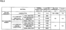
- FIG. 3 is a table of physical properties of the roller main body 31 and the heat equalizing member 36 of the present embodiment.
- carbon fibers are oriented in the axial direction or oriented randomly. For this reason, as shown in FIG.
- the thermal conductivity in the axial direction of the heat equalizing member 36 is higher than the thermal conductivity of the roller main body 31 (at least the thermal conductivity of the inner circumferential surface of the outer cylindrical part 33).
- the heat equalizing member 36 is therefore able to equalize the temperature distribution in the axial direction of the roller surface 31a.
- the electric resistivity in the circumferential direction of the heat equalizing member 36 is higher than the electric resistivity of the outer cylindrical part 33, an eddy current is less likely to flow in the heat equalizing member 36.
- the C/C composite is a non-magnetic material, the magnetic flux scarcely passes through the heat equalizing member 36. Induction heating of the heat equalizing member 36 is therefore suppressed.
- the outer diameter of the heat equalizing member 36 is substantially identical with the inner diameter of the outer cylindrical part 33, and the outer circumferential surface of the heat equalizing member 36 is substantially entirely in contact with the inner circumferential surface of the outer cylindrical part 33.
- the length in the axial direction of the heat equalizing member 36 is substantially identical with the length of the outer cylindrical part 33 of the roller main body 31.
- a leading end portion of the heat equalizing member 36 is inserted into a later-described groove portion 35a.
- a base end portion of the heat equalizing member 36 is fixed to a base end portion of the outer cylindrical part 33 by an annular fixing ring 37.
- the fixing ring 37 is made of, for example, a magnetic material such as carbon steel.
- a flange 38 is provided on the base end side of the roller main body 31.
- the flange 38 is a magnetic body and is, for example, made of carbon steel in the same manner as the roller main body 31.
- the flange 38 is a disc-shaped member, and a through hole 38a is formed at a central part of the flange 38 to allow the output shaft 101 of the motor 100 to be inserted.
- the flange 38 extends radially outward as compared to the coil 41.
- An annular groove 38b is formed in an inner surface of a peripheral edge portion of the flange 38. In this annular groove 38b, the above-described fixing ring 37 is provided not to make contact with surfaces constituting annular groove 38b.
- the heater 40 will be described.
- the heater 40 includes a coil 41 and a bobbin member 42.
- the coil 41 is provided for induction heating of the roller main body 31.
- the coil 41 is wound onto the cylindrical bobbin member 42. In the radial direction, the coil 41 is provided inside the outer cylindrical part 33 of the roller main body 31 and outside the shaft center part 34.
- the bobbin member 42 is made of carbon steel in the same manner as the roller main body 31, for example.
- the bobbin member 42 includes a cylindrical iron core portion 42a on which the coil 41 is wound and a flange portion 42b which protrudes radially outward from a leading end portion of the iron core portion 42a.
- a leading end portion of the bobbin member 42 is slightly separated from the end face part 35, and a base end portion of the bobbin member 42 is attached to the flange 38.
- the bobbin member 42 is partially cut out in the circumferential direction and is therefore C-shaped in cross section. For this reason, an eddy current is unlikely to flow in the bobbin member 42, with the result that induction heating of the bobbin member 42 is suppressed.
- FIG. 4 includes a partial enlarged cross section of the induction heating roller 30 of the present embodiment and a graph showing the temperature distribution of the roller surface.
- a magnetic flux circuit is formed to pass through the iron core portion 42a of the bobbin member 42, the flange portion 42b of the bobbin member 42, the end face part 35 of the roller main body 31, the outer cylindrical part 33 of the roller main body 31, the fixing ring 37, and the flange 38.
- the direction of the magnetic flux changes when the direction of the current changes.
- FIG. 8 includes a partial enlarged cross section of a known induction heating roller 90 and a graph showing the temperature distribution of a roller surface 31a. It should be noted that the components having the same structures as those of the induction heating roller 30 of the embodiment above are given the same reference numerals.
- the magnetic flux mainly passes through a location inside a corner portion between the outer cylindrical part 33 and the end face part 35. For this reason, when the end face part 35 is thick to some extent, the magnetic flux scarcely passes through the leading end portion (indicated by a broken line in FIG. 8 ) of the outer cylindrical part 33, with the result that the leading end portion of the outer cylindrical part 33 is not sufficiently heated. As a result, the temperature of the roller surface 31a is rapidly decreased at the leading end portion, and hence the temperature distribution in the axial direction is uneven. This problem is particularly conspicuous when the roller main body 31 is cantilevered by the motor 100 and the leading end portion of the roller main body 31 is exposed to the outside air.
- the magnetic flux passes through the leading end portion of the outer cylindrical part 33. Because the leading end portion of the outer cylindrical part 33 is heated, the temperature distribution of the roller surface 31a is improved. In this case, however, the rigidity of the end face part 35 is decreased and hence the strength of the roller main body 31 is decreased.
- a groove portion 35a is formed between the outer cylindrical part 33 and the heater 40 in the radial direction in the inner surface of the end face part 35 of the roller main body 31, to be more specific, formed in a part of a region between the inner circumferential surface of the outer cylindrical part 33 and a radially outer end of the flange portion 42b of the bobbin member 42 in the radial direction.
- This groove portion 35a is formed to be adjacent to the outer cylindrical part 33 and annularly extends in the circumferential direction in an uninterrupted manner. In the groove portion 35a, a leading end portion of the heat equalizing member 36 is inserted.
- the groove portion 35a of the present embodiment is triangular in shape in a cross section orthogonal to the circumferential direction, and is narrowed radially outward in a tapered manner. In other words, the groove portion 35a is deepest at the outermost part in the radial direction.
- This arrangement facilitates the magnetic flux, which makes a detour toward the leading end side to circumvent the groove portion 35a, to pass through the leading end portion of the outer cylindrical part 33. It is therefore possible to efficiently heat the leading end portion of the outer cylindrical part 33.
- the minimum thickness of the part of the end face part 35 where the groove portion 35a is formed is, for example, about 3 to 5 millimeters.
- This thickness is less than the thickness (about 6 to 8 millimeters) of the outer cylindrical part 33.
- the minimum thickness is therefore preferably 3 millimeters or more.
- the groove portion 35a extending in the circumferential direction is formed in the region between the outer cylindrical part 33 (equivalent to the heating target of the present invention) and the heater 40 in the radial direction in the inner surface of the end face part 35 of the roller main body 31.
- the magnetic flux passing through the end face part 35 makes a detour toward the leading end side (one end side) in the axial direction to circumvent the groove portion 35a. It is therefore possible to facilitate heat generation at the leading end portion of the roller main body 31, so as to improve the temperature distribution in the axial direction of the roller surface 31a.
- the induction heating roller 30 of the present embodiment makes it possible to equalize the temperature distribution in the axial direction of the roller surface 31a while suppressing deterioration in strength of the roller main body 31.
- the groove portion 35a is an uninterrupted annular groove extending in the circumferential direction. Because the groove portion 35a is annular, heat generation at the leading end portion of the roller main body 31 is facilitated at every part in the circumferential direction. It is therefore possible to effectively equalize the temperature distribution in the axial direction of the roller surface 31a.
- the groove portion 35a is formed to be adjacent to the outer cylindrical part 33.
- the magnetic flux which makes a detour toward the leading end side to circumvent the groove portion 35a passes through the leading end portion of the outer cylindrical part 33. Heat generation at the leading end portion of the outer cylindrical part 33 is therefore facilitated, and the temperature distribution in the axial direction of the roller surface 31a is further effectively equalized.
- the groove portion 35a is formed only in the region between the outer cylindrical part 33 and the heater 40 in the radial direction, in the inner surface of the end face part 35. Because the range of the formation of the groove portion 35a is limited to the region between the outer cylindrical part 33 and the heater 40, decrease in rigidity of the end face part 35 is suppressed and hence decrease in strength of the roller main body 31 is suppressed.
- the groove portion 35a is deepest at the outermost part in the radial direction. Because the depth of the groove portion 35a is arranged in this way, the capacity of the groove portion 35a is small. For this reason, decrease in rigidity of the end face part 35 is suppressed and hence decrease in strength of the roller main body 31 is suppressed. Furthermore, because the groove portion 35a is deepest at the outermost part in the radial direction, the magnetic flux circumventing the deepest part of the groove portion 35a toward the leading end side is guided to pass through leading end portion of the outer cylindrical part 33. Heat generation at the leading end portion of the outer cylindrical part 33 is therefore facilitated, and the temperature distribution in the axial direction of the roller surface 31a is further effectively equalized.
- a part of the end face part 35 where the groove portion 35a is not formed is thicker than the outer cylindrical part 33. This arrangement makes it possible to increase the rigidity of the end face part 35, and therefore to increase the strength of the roller main body 31.
- a part of the end face part 35 where the groove portion 35a is formed is thinner than the outer cylindrical part 33.
- the minimum thickness of the part of the end face part 35 where the groove portion 35a is formed is 3 millimeters or more. This arrangement makes it possible to avoid saturation of the magnetic flux at the thinnest part of the end face part 35, and to suppress the decrease in efficiency of the induction heating.
- the groove portion 35a is filled with the non-magnetic member 36. As compared to a case where the groove portion 35a is a void space, it is possible to increase the rigidity of the end face part 35, and therefore to increase the strength of the roller main body 31.
- the non-magnetic heat equalizing member 36 which has a higher thermal conductivity in the axial direction than the thermal conductivity of at least the inner circumferential surface of the outer cylindrical part 33 is provided to be in contact with the inner circumferential surface of the outer cylindrical part 33, and as the non-magnetic member, a part of the heat equalizing member 36 is inserted into the groove portion 35a. Because of this heat equalizing member 36, it is possible to further effectively equalize the temperature distribution in the axial direction of the roller surface 31a. Furthermore, the groove portion 35a is advantageously reinforced by the heat equalizing member 36.
- the heat equalizing member 36 is made of a fiber composite material.
- the physical properties such as thermal conductivity and electric resistivity are anisotropic.
- the fiber composite material arranged in this way is suitable as a material of the heat equalizing member 36.
- the fiber composite material is C/C composite (carbon fiber reinforced-carbon matrix-composite) including carbon fibers and graphite.
- the C/C composite has high thermal conductivity among fiber composite materials including carbon fibers, and has high heat resistance, too. Accordingly, when the heat equalizing member 36 is made of the C/C composite, the temperature distribution of the roller surface 31a is further effectively equalized and the induction heating roller 30 has high heat resistance.
- the roller main body 31 is cantilevered at the end portion on the base end side (the other end side) in the axial direction.
- the leading end portion is a free end exposed to the outside air, and the temperature of the roller surface 31a tends to significantly decrease.
- the present invention which makes it possible to facilitate heat generation at the leading end portion of the roller main body 31 is therefore particularly effective.
- plural yarns Y are wound onto the outer circumferential surface of the roller main body 31 to be aligned in the axial direction.
- the yarns Y wound on the roller main body 31 are evenly heated, differences in quality between the yarns Y are suppressed, and consequently the quality of the yarns Y is improved.
- the groove portion 35a is triangular in shape in a cross section orthogonal to the circumferential direction.
- the groove portion 35a may be shaped differently.
- a groove portion 35b may be rectangular in cross section as shown in FIG. 5(a)
- a groove portion 35c may be circular-arc-shaped in cross section as shown in FIG. 5(b) .
- the groove portion 35c may have a shape different from these shapes.
- the disclosure is not limited to this arrangement.
- the heat equalizing member 36 may not be inserted into a groove portion 35d as shown in FIG. 6(a) , or the heat equalizing member 36 is omitted and nothing is inserted in a groove portion 35e as shown in FIG. 6(b) .
- the relative permeability of air is lower than that of the roller main body 31 (carbon steel) .
- a groove portion 35f may be filled with a non-magnetic member 39 which is not a heat equalizing member.
- the expression "filled with” is not limited to a case where the groove portion 35a is entirely filled with a non-magnetic member, and encompasses a case where the groove portion 35a is partially filled with a non-magnetic member to the extent that the rigidity of the end face part 35 is improved.
- the groove portion 35a is formed to be adjacent to the outer cylindrical part 33 of the roller main body 31 (i.e., formed at a corner portion between the outer cylindrical part 33 and the end face part 35).
- the groove portion may not be formed to be adjacent to the outer cylindrical part 33.
- the groove portion may be separated from the outer cylindrical part 33 as indicated by a groove portion 35g shown in FIG. 7(b) .
- heat is generated at an the leading end portion of the end face part 35 and hence heating of the leading end portion of the outer cylindrical part 33 is facilitated by heat conduction from the end face part 35.
- the groove portion 35a is an uninterrupted annular groove extending in the circumferential direction.
- the groove portion may not be annular in shape.
- the groove portion may be disconnected in part in the circumferential direction, or may be grooves formed by dividing an annular groove in the circumferential direction.
- the heat equalizing member 36 is made of the C/C composite.
- the heat equalizing member 36 may be made of a CFRP (carbon fiber reinforced plastic) including carbon fibers and resin. CFRP is inferior to C/C composite in heat resistance but is cheaper than C/C composite. When the induction heating roller 30 is not required to have high heat resistance, cost reduction is achieved by making the heat equalizing member 36 of CFRP.
- CFRP carbon fiber reinforced plastic
- the heat equalizing member 36 may be made of not a fiber composite material such as C/C composite and CFRP but a non-magnetic metal material such as aluminum and copper, which has higher thermal conductivity than at least the inner circumferential surface of the outer cylindrical part 33 (carbon steel). Processing of metal materials is typically easier than processing of fiber composite materials. For this reason, the heat equalizing member 36 can be easily shaped when the heat equalizing member 36 is made of a metal material.
- the roller main body 31 is cantilevered. Alternatively, the roller main body 31 may be supported on both sides.
- yarns Y are wound on the outer circumferential surface of the induction heating roller 30.
- the number of yarns Y wound on the outer circumferential surface of the induction heating roller 30 may be one.
- the embodiment above describes the induction heating roller 30 configured to heat the yarns Y.
- the use of the induction heating roller 30 is not limited for heating the yarns Y.
- the roller may be used for heating materials other than the yarns Y, such as a film, paper, nonwoven fabric, a sheet such as a resin sheet, and a toner image on a sheet in a photocopier.
Abstract
Description
- The present invention relates to an induction heating roller and a spun yarn drawing device including the induction heating roller.
- For example, an induction heating roller recited in Patent Literature 1 is arranged such that a heater with a coil is provided inside a roller main body made of a magnetic material, and an outer cylindrical part (heating target) of the roller main body is induction-heated as an alternate current is supplied to the coil. To be more specific, a front lid (hereinafter, end face part) is connected to an end portion of the outer cylindrical part on one end side in the axial direction, whereas a magnetic yoke is provided to be adjacent to the other end side of the outer cylindrical part in the axial direction. When an alternate current is supplied to the coil, an alternating magnetic flux is generated to pass through the iron core of the heater, the end face part, the outer cylindrical part, and the magnetic yoke. As a result, an eddy current is generated by electromagnetic induction to flow in the outer cylindrical part in the circumferential direction, and the outer cylindrical part is heated by Joule heat generated by the eddy current.
- [Patent Literature 1] Japanese Laid-Open Patent Publication No.
54-106617 - Because a magnetic flux has a characteristic of traveling the shortest path, the magnetic flux mainly passes through a location inside a corner portion between the outer cylindrical part and the end face part. For this reason, when the end face part is thick to some extent, the magnetic flux scarcely passes through the one end side of the end face part and the outer cylindrical part, with the result that the one end portion of the roller main body is not sufficiently heated. As a result, the temperature distribution in the axial direction of the outer circumferential surface (roller surface) of the roller main body is disadvantageously uneven. If the thickness of the end face part is reduced, the magnetic flux passes through the one end side of the end face part and the outer cylindrical part. Because heat generation at the one end portion of the roller main body is facilitated, the temperature distribution of the roller surface is improved. In this case, however, the rigidity of the end face part is decreased and hence the strength of the roller main body is decreased.
- To solve the problem above, an object of an induction heating roller of the present invention is to equalize the temperature distribution in the axial direction of a roller surface while suppressing decrease in strength of a roller main body.
- An induction heating roller of the present invention includes: a roller main body including a cylindrical heating target and an end face part connected to an end portion of the heating target on one end side in an axial direction; and a heater including a coil which is provided inside the roller main body, the heating target being induction-heated as an alternate current is supplied to the coil, and in a region between the heating target and the heater in a radial direction in an inner surface of the end face part, a groove portion being formed to extend in a circumferential direction.
- In the present invention, a magnetic flux passing through the end face part makes a detour toward the one end side in the axial direction to circumvent the groove portion. It is therefore possible to facilitate heat generation at the one end portion of the roller main body, so as to improve the temperature distribution in the axial direction of the roller surface. Furthermore, because merely the groove portion is formed in a part of the inner surface of the end face part, the rigidity of the end face part is not significantly lowered. In this way, the present invention makes it possible to equalize the temperature distribution in the axial direction of the roller surface while suppressing deterioration in strength of the roller main body.
- In the present invention, preferably, the groove portion is an uninterrupted annular groove extending in the circumferential direction.
- Because the groove portion is annular, heat generation at the one end portion of the roller main body is facilitated at every part in the circumferential direction. It is therefore possible to effectively equalize the temperature distribution in the axial direction of the roller surface.
- In the present invention, preferably, the groove portion is formed to be adjacent to the heating target.
- When the groove portion is adjacent to the heating target, the magnetic flux which makes a detour toward the one end side to circumvent the groove portion passes through the one end portion of the heating target. Heat generation at the one end portion of the heating target is therefore facilitated, and the temperature distribution in the axial direction of the roller surface is further effectively equalized.
- In the present invention, preferably, the groove portion is formed only in the region between the heating target and the heater in the radial direction, in the inner surface of the end face part.
- Because the range of the formation of the groove portion is limited to the region between the heating target and the heater, decrease in rigidity of the end face part is suppressed and hence decrease in strength of the roller main body is suppressed.
- In the present invention, preferably, the groove portion is deepest at an outermost part in the radial direction.
- Because the depth of the groove portion is arranged in this way, the capacity of the groove portion is small. For this reason, decrease in rigidity of the end face part is suppressed and hence decrease in strength of the roller main body is suppressed. Furthermore, because the groove portion is deepest at the outermost part in the radial direction, the magnetic flux circumventing the deepest part of the groove portion toward the one end side is guided to pass through the one end portion of the heating target. Heat generation at the one end portion of the heating target is therefore facilitated, and the temperature distribution in the axial direction of the roller surface is further effectively equalized.
- In the present invention, preferably, a part of the end face part where the groove portion is not formed is thicker than the heating target.
- This arrangement makes it possible to increase the rigidity of the end face part, and therefore to increase the strength of the roller main body.
- In the present invention, preferably, the minimum thickness of a part of the end face part where the groove portion is formed is less than the thickness of the heating target.
- With this arrangement, the path of the magnetic flux passing at the deepest part of the groove portion (i.e., the thinnest part of the end face part) is further shifted to the one end side. Heat generation at the one end portion of the roller main body is therefore further facilitated, and the temperature distribution in the axial direction of the roller surface is further effectively equalized.
- In the present invention, preferably, the minimum thickness of the part of the end face part where the groove portion is formed is 3 millimeters or more.
- This arrangement makes it possible to avoid saturation of the magnetic flux at the thinnest part of the end face part, and to suppress the decrease in efficiency of the induction heating.
- In the present invention, preferably, the groove portion is filled with a non-magnetic member.
- As compared to a case where the groove portion is a void space, it is possible to increase the rigidity of the end face part, and therefore to increase the strength of the roller main body.
- In the present invention, preferably, the induction heating roller further includes a non-magnetic heat equalizing member which is provided to be in contact with an inner circumferential surface of the heating target and is higher in thermal conductivity in the axial direction than at least the inner circumferential surface of the heating target, as the non-magnetic member, a part of the heat equalizing member being inserted into the groove portion.
- Because of this heat equalizing member, it is possible to further effectively equalize the temperature distribution in the axial direction of the roller surface. Furthermore, the groove portion is advantageously reinforced by the heat equalizing member.
- In the present invention, preferably, the heat equalizing member is made of a fiber composite material.
- When the orientation of fibers in the fiber composite material is suitably arranged, the physical properties such as thermal conductivity and electric resistivity are anisotropic. The fiber composite material arranged in this way is suitable as a material of the heat equalizing member.
- In the present invention, preferably, the heat equalizing member is made of a non-magnetic metal material which is higher in thermal conductivity than at least the inner circumferential surface of the heating target.
- Processing of metal materials is typically easier than processing of fiber composite materials. For this reason, the heat equalizing member can be easily shaped when the heat equalizing member is made of a metal material.
- In the present invention, preferably, the roller main body is cantilevered at an end portion on the other end side in the axial direction.
- When the roller main body is cantilevered at an end portion on the other end side, the one end portion of the roller main body is a free end exposed to the outside air, and the temperature of the roller surface tends to significantly decrease. The present invention which makes it possible to facilitate heat generation at the one end portion of the roller main body is therefore particularly effective.
- A spun yarn drawing device of the present invention includes any one of the above-described induction heating rollers, yarns being wound on an outer circumferential surface of the roller main body to be aligned in the axial direction.
- In the present invention, it is possible to equalize the temperature distribution in the axial direction of the roller surface. The yarns wound on the roller main body are evenly heated, differences in quality between the yarns are suppressed, and consequently the quality of the yarns is improved.
-
-
FIG. 1 is a schematic diagram of a spun yarn take-up machine including an induction heating roller of an embodiment. -
FIG. 2 is a cross section of the induction heating roller of the embodiment, which is taken along an axial direction. -
FIG. 3 is a table of physical properties of a roller main body and a heat equalizing member of the embodiment. -
FIG. 4 includes a partial enlarged cross section of the induction heating roller of the embodiment and a graph showing the temperature distribution of a roller surface. -
FIG. 5 is a cross section of an induction heating roller of a modification. -
FIG. 6 is a cross section of an induction heating roller of a modification. -
FIG. 7 is a cross section of an induction heating roller of a modification. -
FIG. 8 includes a partial enlarged cross section of a known induction heating roller and a graph showing the temperature distribution of a roller surface. - The following will describe an embodiment of the present invention.
FIG. 1 is a schematic diagram of a spun yarn take-up machine including an induction heating roller of the present embodiment. As shown inFIG. 1 , the spun yarn take-up machine 1 is configured to draw, by a spunyarn drawing device 3, plural (six in this embodiment) yarns Y serially spun out from a spinning apparatus 2 and made of a solidified molten fibrous material such as polyester, and then to wind the yarns Y by ayarn winding apparatus 4. Hereinafter, explanations will be given with reference to the directions shown in the figures. - The spinning apparatus 2 is configured to generate the yarns Y by continuously spinning out a molten fibrous material such as polyester. To the yarns Y spun out from the spinning apparatus 2, oil is applied at an
oil guide 10. The yarns Y are then sent to the spunyarn drawing device 3 via aguide roller 11. - The spun
yarn drawing device 3 is an apparatus for heating and drawing the yarns Y and is provided below the spinning apparatus 2. The spunyarn drawing device 3 includes plural (five in this embodiment)godet rollers 21 to 25 housed in athermal insulation box 12. Thegodet rollers 21 to 25 are induction heating rollers which are rotationally driven by a motor and are induction-heated by power supply to a coil. Yarns Y are wound onto thegodet rollers 21 to 25. At a lower part of a right side portion of thethermal insulation box 12, aninlet 12a is formed to introduce yarns Y into thethermal insulation box 12. At an upper part of the right side portion of thethermal insulation box 12, anoutlet 12b is formed to take yarns Y out from thethermal insulation box 12. The yarns Y are wound onto each of thegodet rollers 21 to 25 at a winding angle of less than 360 degrees. The yarns Y are wound onto thegodet rollers 21 to 25 in order, from thelowest godet roller 21. - The lower three
godet rollers 21 to 23 are preheating rollers for preliminarily heating the yarns Y before drawing them. The roller surface temperature of each of these rollers is arranged to be equal to or higher than the glass transition temperature of the yarns Y (e.g., set at about 90 to 100 degrees centigrade). Meanwhile, the upper twogodet rollers godet rollers 21 to 23 (e.g., set at about 150 to 200 degrees centigrade). The yarn feeding speeds of the upper twogodet rollers godet rollers 21 to 23. - The yarns Y introduced into the
thermal insulation box 12 through theinlet 12a are, to begin with, preliminarily heated to a drawable temperature while being transferred by thegodet rollers 21 to 23. The preliminarily-heated yarns Y are drawn on account of a difference in yarn feeding speed between thegodet roller 23 and thegodet roller 24. The yarns Y are then further heated while being transferred by thegodet rollers thermal insulation box 12 through theoutlet 12b. - The yarns Y drawn by the spun
yarn drawing device 3 are sent to theyarn winding apparatus 4 via aguide roller 13. Theyarn winding apparatus 4 is an apparatus for winding the yarns Y and is provided below the spunyarn drawing device 3. Theyarn winding apparatus 4 includes members such as a bobbin holder 14 and acontact roller 15. The bobbin holder 14 is cylindrical in shape and extends in the front-rear direction. The bobbin holder 14 is rotationally driven by an unillustrated motor. To the bobbin holder 14, bobbins B are attached along the axial direction to be side by side. By rotating the bobbin holder 14, theyarn winding apparatus 4 simultaneously winds the yarns Y onto the bobbins B, so as to produce packages P. Thecontact roller 15 makes contact with the surfaces of the packages P to adjust the shape of each package P by applying a predetermined contact pressure to each package P. - The following will describe an
induction heating roller 30 which is used as thegodet rollers 21 to 25, with reference toFIG. 2. FIG. 2 is a cross section of theinduction heating roller 30 of the present embodiment, which is taken along an axial direction. A rollermain body 31 of theinduction heating roller 30 is cantilevered by amotor 100 which rotationally drives the rollermain body 31. Hereinafter, a direction in which the cylindrical rollermain body 31 extends (i.e., the left-right direction inFIG. 2 ) will be referred to as an axial direction. In the axial direction, the leading end side of the roller main body 31 (i.e., the right side inFIG. 2 ) is equivalent to one end side in the present invention, whereas the base end side opposite to the leading end side (i.e., the left side inFIG. 2 ) is equivalent to the other end side in the present invention. Furthermore, the radial direction of the rollermain body 31 may be simply referred to as radial direction, and the circumferential direction of the rollermain body 31 may be simply referred to as circumferential direction. - The
induction heating roller 30 includes a cylindrical rollermain body 31 extending in the axial direction and aheater 40 which is configured to heat an outer circumferential surface (hereinafter, aroller surface 31a) of the rollermain body 31. Theinduction heating roller 30 is configured to heat theroller surface 31a by induction heating by acoil 41 provided in theheater 40. With this, yarns Y wound on theroller surface 31a to be aligned in the axial direction are heated. - The roller
main body 31 is made of carbon steel which is a magnetic body and a conductor. The rollermain body 31 is arranged such that a cylindrical outercylindrical part 33, a cylindricalshaft center part 34, and a disc-shaped end facepart 35 are integrally formed. The outercylindrical part 33 is provided radially outside thecoil 41. Theshaft center part 34 is provided radially inside thecoil 41. The end facepart 35 connects a leading end portion of theheating target 33 with a leading end portion of theshaft center part 34. In this regard, when each of the outercylindrical part 33 and the end facepart 35 is a magnetic body and a conductor, the outercylindrical part 33 and the end facepart 35 may be made of different materials. Even when the outercylindrical part 33 and the end facepart 35 are made of the same material, the outercylindrical part 33 and the end facepart 35 may be different members. The base end side of the rollermain body 31 is open, and anoutput shaft 101 of themotor 100 is inserted through this opening into the rollermain body 31. - At the
shaft center part 34 of the rollermain body 31, ashaft inserting hole 34a is formed to extend along the axial direction. To theshaft inserting hole 34a, theoutput shaft 101 of themotor 100 inserted from the base end side is fixed by unillustrated fixing means. As a result, the base end portion of the rollermain body 31 is cantilevered by theoutput shaft 101 of themotor 100, and hence the rollermain body 31 and theoutput shaft 101 are rotatable together. - In the present embodiment, in order to efficiently heat the
roller surface 31a, the outercylindrical part 33 is thin to some degree, i.e., about 6 to 8 millimeters in thickness. When the end facepart 35 is more or less as thick as the outercylindrical part 33, the strength of the rollermain body 31 may be insufficient. For this reason, the end facepart 35 is thicker than the outercylindrical part 33, i.e., about 8 to 10 millimeters in thickness. This thickness is a mere example, and the outercylindrical part 33 may be as thick as or thicker than the end facepart 35. - Inside the roller
main body 31, a cylindricalheat equalizing member 36 is provided to be in contact with an inner circumferential surface of the outercylindrical part 33. Theheat equalizing member 36 is made of C/C composite (carbon fiber reinforced-carbon matrix-composite) including carbon fibers and graphite, for example.FIG. 3 is a table of physical properties of the rollermain body 31 and theheat equalizing member 36 of the present embodiment. In the C/C composite of which theheat equalizing member 36 made, carbon fibers are oriented in the axial direction or oriented randomly. For this reason, as shown inFIG. 3 , the thermal conductivity in the axial direction of theheat equalizing member 36 is higher than the thermal conductivity of the roller main body 31 (at least the thermal conductivity of the inner circumferential surface of the outer cylindrical part 33). Theheat equalizing member 36 is therefore able to equalize the temperature distribution in the axial direction of theroller surface 31a. Furthermore, because the electric resistivity in the circumferential direction of theheat equalizing member 36 is higher than the electric resistivity of the outercylindrical part 33, an eddy current is less likely to flow in theheat equalizing member 36. Furthermore, because the C/C composite is a non-magnetic material, the magnetic flux scarcely passes through theheat equalizing member 36. Induction heating of theheat equalizing member 36 is therefore suppressed. - Referring back to
FIG. 2 , the outer diameter of theheat equalizing member 36 is substantially identical with the inner diameter of the outercylindrical part 33, and the outer circumferential surface of theheat equalizing member 36 is substantially entirely in contact with the inner circumferential surface of the outercylindrical part 33. The length in the axial direction of theheat equalizing member 36 is substantially identical with the length of the outercylindrical part 33 of the rollermain body 31. A leading end portion of theheat equalizing member 36 is inserted into a later-describedgroove portion 35a. A base end portion of theheat equalizing member 36 is fixed to a base end portion of the outercylindrical part 33 by anannular fixing ring 37. The fixingring 37 is made of, for example, a magnetic material such as carbon steel. - A
flange 38 is provided on the base end side of the rollermain body 31. Theflange 38 is a magnetic body and is, for example, made of carbon steel in the same manner as the rollermain body 31. Theflange 38 is a disc-shaped member, and a throughhole 38a is formed at a central part of theflange 38 to allow theoutput shaft 101 of themotor 100 to be inserted. Theflange 38 extends radially outward as compared to thecoil 41. Anannular groove 38b is formed in an inner surface of a peripheral edge portion of theflange 38. In thisannular groove 38b, the above-describedfixing ring 37 is provided not to make contact with surfaces constitutingannular groove 38b. - The
heater 40 will be described. Theheater 40 includes acoil 41 and abobbin member 42. Thecoil 41 is provided for induction heating of the rollermain body 31. Thecoil 41 is wound onto thecylindrical bobbin member 42. In the radial direction, thecoil 41 is provided inside the outercylindrical part 33 of the rollermain body 31 and outside theshaft center part 34. - The
bobbin member 42 is made of carbon steel in the same manner as the rollermain body 31, for example. Thebobbin member 42 includes a cylindricaliron core portion 42a on which thecoil 41 is wound and aflange portion 42b which protrudes radially outward from a leading end portion of theiron core portion 42a. A leading end portion of thebobbin member 42 is slightly separated from the end facepart 35, and a base end portion of thebobbin member 42 is attached to theflange 38. Although not illustrated, thebobbin member 42 is partially cut out in the circumferential direction and is therefore C-shaped in cross section. For this reason, an eddy current is unlikely to flow in thebobbin member 42, with the result that induction heating of thebobbin member 42 is suppressed. -
FIG. 4 includes a partial enlarged cross section of theinduction heating roller 30 of the present embodiment and a graph showing the temperature distribution of the roller surface. When a highfrequency current is supplied to thecoil 41, a variable magnetic field is generated around thecoil 41. As a result, an eddy current is generated by electromagnetic induction to flow in the outercylindrical part 33 of the rollermain body 31 in the circumferential direction, and the outercylindrical part 33 is heated by Joule heat generated by the eddy current. Consequently, the temperature of theroller surface 31a increases. At this stage, as indicated by arrows inFIG. 4 , a magnetic flux circuit is formed to pass through theiron core portion 42a of thebobbin member 42, theflange portion 42b of thebobbin member 42, the end facepart 35 of the rollermain body 31, the outercylindrical part 33 of the rollermain body 31, the fixingring 37, and theflange 38. The direction of the magnetic flux changes when the direction of the current changes. -
FIG. 8 includes a partial enlarged cross section of a knowninduction heating roller 90 and a graph showing the temperature distribution of aroller surface 31a. It should be noted that the components having the same structures as those of theinduction heating roller 30 of the embodiment above are given the same reference numerals. - Because a magnetic flux has a characteristic of traveling the shortest path, the magnetic flux mainly passes through a location inside a corner portion between the outer
cylindrical part 33 and the end facepart 35. For this reason, when the end facepart 35 is thick to some extent, the magnetic flux scarcely passes through the leading end portion (indicated by a broken line inFIG. 8 ) of the outercylindrical part 33, with the result that the leading end portion of the outercylindrical part 33 is not sufficiently heated. As a result, the temperature of theroller surface 31a is rapidly decreased at the leading end portion, and hence the temperature distribution in the axial direction is uneven. This problem is particularly conspicuous when the rollermain body 31 is cantilevered by themotor 100 and the leading end portion of the rollermain body 31 is exposed to the outside air. - If the thickness of the end face
part 35 is reduced, the magnetic flux passes through the leading end portion of the outercylindrical part 33. Because the leading end portion of the outercylindrical part 33 is heated, the temperature distribution of theroller surface 31a is improved. In this case, however, the rigidity of the end facepart 35 is decreased and hence the strength of the rollermain body 31 is decreased. - To solve the problem above, in the present embodiment, as shown in
FIG. 4 , agroove portion 35a is formed between the outercylindrical part 33 and theheater 40 in the radial direction in the inner surface of the end facepart 35 of the rollermain body 31, to be more specific, formed in a part of a region between the inner circumferential surface of the outercylindrical part 33 and a radially outer end of theflange portion 42b of thebobbin member 42 in the radial direction. Thisgroove portion 35a is formed to be adjacent to the outercylindrical part 33 and annularly extends in the circumferential direction in an uninterrupted manner. In thegroove portion 35a, a leading end portion of theheat equalizing member 36 is inserted. - Even though the
heat equalizing member 36 is inserted into thegroove portion 35a, a magnetic flux scarcely passes through theheat equalizing member 36 because theheat equalizing member 36 is a non-magnetic body. The magnetic flux therefore makes a detour toward the leading end side of the end facepart 35 and outercylindrical part 33 of the rollermain body 31 in order to circumvent thegroove portion 35a (heat equalizing member 36) (see a part indicated by a broken line inFIG. 4 ). As a result, an amount of heat generated at the leading end portion of the outercylindrical part 33 is increased, and hence the temperature distribution of theroller surface 31a is equalized. - The
groove portion 35a of the present embodiment is triangular in shape in a cross section orthogonal to the circumferential direction, and is narrowed radially outward in a tapered manner. In other words, thegroove portion 35a is deepest at the outermost part in the radial direction. This arrangement facilitates the magnetic flux, which makes a detour toward the leading end side to circumvent thegroove portion 35a, to pass through the leading end portion of the outercylindrical part 33. It is therefore possible to efficiently heat the leading end portion of the outercylindrical part 33. The minimum thickness of the part of the end facepart 35 where thegroove portion 35a is formed (i.e., the thickness at the deepest part of thegroove portion 35a) is, for example, about 3 to 5 millimeters. This thickness is less than the thickness (about 6 to 8 millimeters) of the outercylindrical part 33. The less the minimum thickness is, the more the path of the magnetic flux is shifted to the leading end side. However, when the minimum thickness is excessively short, the magnetic flux is saturated and the heating efficiency is deteriorated. The minimum thickness is therefore preferably 3 millimeters or more. - In the
induction heating roller 30 of the present embodiment, thegroove portion 35a extending in the circumferential direction is formed in the region between the outer cylindrical part 33 (equivalent to the heating target of the present invention) and theheater 40 in the radial direction in the inner surface of the end facepart 35 of the rollermain body 31. With this arrangement, the magnetic flux passing through the end facepart 35 makes a detour toward the leading end side (one end side) in the axial direction to circumvent thegroove portion 35a. It is therefore possible to facilitate heat generation at the leading end portion of the rollermain body 31, so as to improve the temperature distribution in the axial direction of theroller surface 31a. Furthermore, because merely thegroove portion 35a is formed in a part of the inner surface of the end facepart 35, the rigidity of the end facepart 35 is not significantly lowered. In this way, theinduction heating roller 30 of the present embodiment makes it possible to equalize the temperature distribution in the axial direction of theroller surface 31a while suppressing deterioration in strength of the rollermain body 31. - In the present embodiment, the
groove portion 35a is an uninterrupted annular groove extending in the circumferential direction. Because thegroove portion 35a is annular, heat generation at the leading end portion of the rollermain body 31 is facilitated at every part in the circumferential direction. It is therefore possible to effectively equalize the temperature distribution in the axial direction of theroller surface 31a. - In the present embodiment, the
groove portion 35a is formed to be adjacent to the outercylindrical part 33. When thegroove portion 35a is adjacent to the outercylindrical part 33, the magnetic flux which makes a detour toward the leading end side to circumvent thegroove portion 35a passes through the leading end portion of the outercylindrical part 33. Heat generation at the leading end portion of the outercylindrical part 33 is therefore facilitated, and the temperature distribution in the axial direction of theroller surface 31a is further effectively equalized. - In the present embodiment, the
groove portion 35a is formed only in the region between the outercylindrical part 33 and theheater 40 in the radial direction, in the inner surface of the end facepart 35. Because the range of the formation of thegroove portion 35a is limited to the region between the outercylindrical part 33 and theheater 40, decrease in rigidity of the end facepart 35 is suppressed and hence decrease in strength of the rollermain body 31 is suppressed. - In the present embodiment, the
groove portion 35a is deepest at the outermost part in the radial direction. Because the depth of thegroove portion 35a is arranged in this way, the capacity of thegroove portion 35a is small. For this reason, decrease in rigidity of the end facepart 35 is suppressed and hence decrease in strength of the rollermain body 31 is suppressed. Furthermore, because thegroove portion 35a is deepest at the outermost part in the radial direction, the magnetic flux circumventing the deepest part of thegroove portion 35a toward the leading end side is guided to pass through leading end portion of the outercylindrical part 33. Heat generation at the leading end portion of the outercylindrical part 33 is therefore facilitated, and the temperature distribution in the axial direction of theroller surface 31a is further effectively equalized. - In the present embodiment, a part of the end face
part 35 where thegroove portion 35a is not formed is thicker than the outercylindrical part 33. This arrangement makes it possible to increase the rigidity of the end facepart 35, and therefore to increase the strength of the rollermain body 31. - In the present embodiment, a part of the end face
part 35 where thegroove portion 35a is formed is thinner than the outercylindrical part 33. With this arrangement, the path of the magnetic flux passing at the deepest part of thegroove portion 35a (i.e., the thinnest part of the end face part 35) is further shifted to the leading end side. Heat generation at the leading end portion of the rollermain body 31 is therefore further facilitated, and the temperature distribution in the axial direction of theroller surface 31a is further effectively equalized. - In the present embodiment, the minimum thickness of the part of the end face
part 35 where thegroove portion 35a is formed is 3 millimeters or more. This arrangement makes it possible to avoid saturation of the magnetic flux at the thinnest part of the end facepart 35, and to suppress the decrease in efficiency of the induction heating. - In the present embodiment, the
groove portion 35a is filled with thenon-magnetic member 36. As compared to a case where thegroove portion 35a is a void space, it is possible to increase the rigidity of the end facepart 35, and therefore to increase the strength of the rollermain body 31. - In the present embodiment, the non-magnetic
heat equalizing member 36 which has a higher thermal conductivity in the axial direction than the thermal conductivity of at least the inner circumferential surface of the outercylindrical part 33 is provided to be in contact with the inner circumferential surface of the outercylindrical part 33, and as the non-magnetic member, a part of theheat equalizing member 36 is inserted into thegroove portion 35a. Because of thisheat equalizing member 36, it is possible to further effectively equalize the temperature distribution in the axial direction of theroller surface 31a. Furthermore, thegroove portion 35a is advantageously reinforced by theheat equalizing member 36. - In the present embodiment, the
heat equalizing member 36 is made of a fiber composite material. When the orientation of fibers in the fiber composite material is suitably arranged, the physical properties such as thermal conductivity and electric resistivity are anisotropic. The fiber composite material arranged in this way is suitable as a material of theheat equalizing member 36. - In the present embodiment, the fiber composite material is C/C composite (carbon fiber reinforced-carbon matrix-composite) including carbon fibers and graphite. The C/C composite has high thermal conductivity among fiber composite materials including carbon fibers, and has high heat resistance, too. Accordingly, when the
heat equalizing member 36 is made of the C/C composite, the temperature distribution of theroller surface 31a is further effectively equalized and theinduction heating roller 30 has high heat resistance. - In the present embodiment, the roller
main body 31 is cantilevered at the end portion on the base end side (the other end side) in the axial direction. When the rollermain body 31 is cantilevered at the base end portion, the leading end portion is a free end exposed to the outside air, and the temperature of theroller surface 31a tends to significantly decrease. The present invention which makes it possible to facilitate heat generation at the leading end portion of the rollermain body 31 is therefore particularly effective. - In the present embodiment, plural yarns Y are wound onto the outer circumferential surface of the roller
main body 31 to be aligned in the axial direction. In the present invention, it is possible to equalize the temperature distribution in the axial direction of theroller surface 31a. The yarns Y wound on the rollermain body 31 are evenly heated, differences in quality between the yarns Y are suppressed, and consequently the quality of the yarns Y is improved. - The following will describe modifications of the above-described embodiment.
- In the embodiment above, the
groove portion 35a is triangular in shape in a cross section orthogonal to the circumferential direction. Thegroove portion 35a may be shaped differently. For example, agroove portion 35b may be rectangular in cross section as shown inFIG. 5(a) , or agroove portion 35c may be circular-arc-shaped in cross section as shown inFIG. 5(b) . Thegroove portion 35c may have a shape different from these shapes. - While in the embodiment above the leading end portion of the
heat equalizing member 36 is inserted into thegroove portion 35a, the disclosure is not limited to this arrangement. For example, theheat equalizing member 36 may not be inserted into agroove portion 35d as shown inFIG. 6(a) , or theheat equalizing member 36 is omitted and nothing is inserted in agroove portion 35e as shown inFIG. 6(b) . Even in a simple space such as thegroove portions part 35 makes a detour toward the leading end side to circumvent thegroove portion cylindrical part 33 is facilitated. Alternatively, as shown inFIG. 7(a) , agroove portion 35f may be filled with anon-magnetic member 39 which is not a heat equalizing member. The expression "filled with" is not limited to a case where thegroove portion 35a is entirely filled with a non-magnetic member, and encompasses a case where thegroove portion 35a is partially filled with a non-magnetic member to the extent that the rigidity of the end facepart 35 is improved. - In the embodiment above, the
groove portion 35a is formed to be adjacent to the outercylindrical part 33 of the roller main body 31 (i.e., formed at a corner portion between the outercylindrical part 33 and the end face part 35). In this regard, the groove portion may not be formed to be adjacent to the outercylindrical part 33. For example, as long as the groove portion is formed in a region between the outercylindrical part 33 and theheater 40 in the radial direction, the groove portion may be separated from the outercylindrical part 33 as indicated by agroove portion 35g shown inFIG. 7(b) . Also in this case, heat is generated at an the leading end portion of the end facepart 35 and hence heating of the leading end portion of the outercylindrical part 33 is facilitated by heat conduction from the end facepart 35. - In the embodiment above, the
groove portion 35a is an uninterrupted annular groove extending in the circumferential direction. In this regard, the groove portion may not be annular in shape. The groove portion may be disconnected in part in the circumferential direction, or may be grooves formed by dividing an annular groove in the circumferential direction. - In the embodiment above, the
heat equalizing member 36 is made of the C/C composite. Alternatively, theheat equalizing member 36 may be made of a CFRP (carbon fiber reinforced plastic) including carbon fibers and resin. CFRP is inferior to C/C composite in heat resistance but is cheaper than C/C composite. When theinduction heating roller 30 is not required to have high heat resistance, cost reduction is achieved by making theheat equalizing member 36 of CFRP. - The
heat equalizing member 36 may be made of not a fiber composite material such as C/C composite and CFRP but a non-magnetic metal material such as aluminum and copper, which has higher thermal conductivity than at least the inner circumferential surface of the outer cylindrical part 33 (carbon steel). Processing of metal materials is typically easier than processing of fiber composite materials. For this reason, theheat equalizing member 36 can be easily shaped when theheat equalizing member 36 is made of a metal material. - In the embodiment above, the roller
main body 31 is cantilevered. Alternatively, the rollermain body 31 may be supported on both sides. - In the embodiment above, yarns Y are wound on the outer circumferential surface of the
induction heating roller 30. In this regard, the number of yarns Y wound on the outer circumferential surface of theinduction heating roller 30 may be one. - The embodiment above describes the
induction heating roller 30 configured to heat the yarns Y. In this regard, the use of theinduction heating roller 30 is not limited for heating the yarns Y. The roller may be used for heating materials other than the yarns Y, such as a film, paper, nonwoven fabric, a sheet such as a resin sheet, and a toner image on a sheet in a photocopier. -
- 3
- spun yarn drawing device
- 30
- induction heating roller
- 31
- roller main body
- 31a
- roller surface
- 33
- outer cylindrical part (heating target)
- 35
- end face portion
- 35a to 35g
- groove portions
- 36
- heat equalizing member (non-magnetic member)
- 40
- heater
- 41
- coil
- Y
- yarn
Claims (14)
- An induction heating roller comprising:a roller main body including a cylindrical heating target and an end face part connected to an end portion of the heating target on one end side in an axial direction; anda heater including a coil which is provided inside the roller main body,the heating target being induction-heated as an alternate current is supplied to the coil, andin a region between the heating target and the heater in a radial direction in an inner surface of the end face part, a groove portion being formed to extend in a circumferential direction.
- The induction heating roller according to claim 1, wherein, the groove portion is an uninterrupted annular groove extending in the circumferential direction.
- The induction heating roller according to claim 1 or 2, wherein, the groove portion is formed to be adjacent to the heating target.
- The induction heating roller according to any one of claims 1 to 3, wherein, the groove portion is formed only in the region between the heating target and the heater in the radial direction, in the inner surface of the end face part.
- The induction heating roller according to any one of claims 1 to 4, wherein, the groove portion is deepest at an outermost part in the radial direction.
- The induction heating roller according to any one of claims 1 to 5, wherein, a part of the end face part where the groove portion is not formed is thicker than the heating target.
- The induction heating roller according to any one of claims 1 to 6, wherein, the minimum thickness of a part of the end face part where the groove portion is formed is less than the thickness of the heating target.
- The induction heating roller according to any one of claims 1 to 7, wherein, the minimum thickness of the part of the end face part where the groove portion is formed is 3 millimeters or more.
- The induction heating roller according to any one of claims 1 to 8, wherein, the groove portion is filled with a non-magnetic member.
- The induction heating roller according to claim 9, further comprising
a non-magnetic heat equalizing member which is provided to be in contact with an inner circumferential surface of the heating target and is higher in thermal conductivity in the axial direction than at least the inner circumferential surface of the heating target, as the non-magnetic member, a part of the heat equalizing member being inserted into the groove portion. - The induction heating roller according to claim 10, wherein, the heat equalizing member is made of a fiber composite material.
- The induction heating roller according to claim 10, wherein, the heat equalizing member is made of a non-magnetic metal material which is higher in thermal conductivity than at least the inner circumferential surface of the heating target.
- The induction heating roller according to any one of claims 1 to 12, wherein, the roller main body is cantilevered at an end portion on the other end side in the axial direction.
- A spun yarn drawing device comprising the induction heating roller of any one of claims 1 to 13,
yarns being wound on an outer circumferential surface of the roller main body to be aligned in the axial direction.
Applications Claiming Priority (4)
| Application Number | Priority Date | Filing Date | Title |
|---|---|---|---|
| JP2017200810 | 2017-10-17 | ||
| JP2018030816 | 2018-02-23 | ||
| JP2018072511 | 2018-04-04 | ||
| PCT/JP2018/032854 WO2019077899A1 (en) | 2017-10-17 | 2018-09-05 | Induction heating roller and spun yarn drawing device |
Publications (2)
| Publication Number | Publication Date |
|---|---|
| EP3700300A1 true EP3700300A1 (en) | 2020-08-26 |
| EP3700300A4 EP3700300A4 (en) | 2021-08-04 |
Family
ID=66173336
Family Applications (1)
| Application Number | Title | Priority Date | Filing Date |
|---|---|---|---|
| EP18868728.9A Pending EP3700300A4 (en) | 2017-10-17 | 2018-09-05 | Induction heating roller and spun yarn drawing device |
Country Status (5)
| Country | Link |
|---|---|
| EP (1) | EP3700300A4 (en) |
| JP (1) | JP6966565B2 (en) |
| CN (2) | CN111165071B (en) |
| TW (1) | TWI739035B (en) |
| WO (1) | WO2019077899A1 (en) |
Families Citing this family (1)
| Publication number | Priority date | Publication date | Assignee | Title |
|---|---|---|---|---|
| JP2021190420A (en) * | 2020-05-27 | 2021-12-13 | Tmtマシナリー株式会社 | Induction heating roller, and, spinning stretching device |
Family Cites Families (15)
| Publication number | Priority date | Publication date | Assignee | Title |
|---|---|---|---|---|
| CH557902A (en) * | 1971-07-20 | 1975-01-15 | Bernex Oberflaechenmetallurgie | Heated roller for synthetic fibres - has a ceramic cladding keyed to a steel or aluminium roller body |
| US4208560A (en) * | 1974-10-16 | 1980-06-17 | Barmag Barmer Maschinenfabrik Ag | Inductively heated godet |
| JPS5410032Y2 (en) * | 1977-03-10 | 1979-05-10 | ||
| JPS607733B2 (en) | 1978-02-07 | 1985-02-26 | 特殊電機株式会社 | induction heating roller |
| JPS54157354A (en) * | 1978-06-02 | 1979-12-12 | Teijin Ltd | Induction heat generating roller |
| JPS60136375U (en) * | 1984-12-28 | 1985-09-10 | 特殊電機株式会社 | induction heating roller |
| JPH01103412A (en) * | 1987-10-19 | 1989-04-20 | Teijin Ltd | Method of heating roll |
| EP0349829B1 (en) * | 1988-06-30 | 1996-04-17 | Maschinenfabrik Rieter Ag | Roller with a large rotating speed range |
| JPH09127810A (en) * | 1995-10-27 | 1997-05-16 | Minolta Co Ltd | Fixing device by induction heating |
| CN201378252Y (en) * | 2009-01-08 | 2010-01-06 | 特新机电(东莞)有限公司 | Roller used for electrophotograph device |
| JP5792991B2 (en) * | 2011-05-02 | 2015-10-14 | トクデン株式会社 | Induction heating roller device |
| JP5839839B2 (en) * | 2011-05-19 | 2016-01-06 | キヤノン株式会社 | Fixing device |
| EP2664428B1 (en) * | 2012-05-16 | 2016-03-23 | UHLMANN PAC-SYSTEME GmbH & Co. KG | Sealing roller |
| JP6258610B2 (en) * | 2012-06-27 | 2018-01-10 | Tmtマシナリー株式会社 | Spinning and drawing equipment |
| JP6668163B2 (en) * | 2015-05-25 | 2020-03-18 | Tmtマシナリー株式会社 | Yarn heating device |
-
2018
- 2018-09-05 EP EP18868728.9A patent/EP3700300A4/en active Pending
- 2018-09-05 WO PCT/JP2018/032854 patent/WO2019077899A1/en unknown
- 2018-09-05 CN CN201880064711.1A patent/CN111165071B/en active Active
- 2018-09-05 JP JP2019549148A patent/JP6966565B2/en active Active
- 2018-09-05 CN CN202211173999.0A patent/CN115460727A/en active Pending
- 2018-09-18 TW TW107132746A patent/TWI739035B/en active
Also Published As
| Publication number | Publication date |
|---|---|
| EP3700300A4 (en) | 2021-08-04 |
| CN115460727A (en) | 2022-12-09 |
| JPWO2019077899A1 (en) | 2020-11-19 |
| WO2019077899A1 (en) | 2019-04-25 |
| TWI739035B (en) | 2021-09-11 |
| CN111165071A (en) | 2020-05-15 |
| CN111165071B (en) | 2023-03-21 |
| JP6966565B2 (en) | 2021-11-17 |
| TW201917242A (en) | 2019-05-01 |
Similar Documents
| Publication | Publication Date | Title |
|---|---|---|
| EP3288339B1 (en) | Induction heating roller | |
| EP3700300A1 (en) | Induction heating roller and spun yarn drawing device | |
| EP3758444B1 (en) | Induction heating roller and spun yarn take-up machine | |
| CN111194577B (en) | Induction heating roller and spinning stretching device | |
| EP3758445A1 (en) | Heating roller and spun yarn drawing device | |
| EP3700301B1 (en) | Induction heating roller and spun yarn drawing device | |
| EP3917282A1 (en) | Induction heating roller and spun yarn drawing device | |
| JP2004526885A (en) | Godet | |
| JP4887979B2 (en) | Induction heating roller device |
Legal Events
| Date | Code | Title | Description |
|---|---|---|---|
| STAA | Information on the status of an ep patent application or granted ep patent |
Free format text: STATUS: THE INTERNATIONAL PUBLICATION HAS BEEN MADE |
|
| PUAI | Public reference made under article 153(3) epc to a published international application that has entered the european phase |
Free format text: ORIGINAL CODE: 0009012 |
|
| STAA | Information on the status of an ep patent application or granted ep patent |
Free format text: STATUS: REQUEST FOR EXAMINATION WAS MADE |
|
| 17P | Request for examination filed |
Effective date: 20200414 |
|
| AK | Designated contracting states |
Kind code of ref document: A1 Designated state(s): AL AT BE BG CH CY CZ DE DK EE ES FI FR GB GR HR HU IE IS IT LI LT LU LV MC MK MT NL NO PL PT RO RS SE SI SK SM TR |
|
| AX | Request for extension of the european patent |
Extension state: BA ME |
|
| DAV | Request for validation of the european patent (deleted) | ||
| DAX | Request for extension of the european patent (deleted) | ||
| A4 | Supplementary search report drawn up and despatched |
Effective date: 20210705 |
|
| RIC1 | Information provided on ipc code assigned before grant |
Ipc: H05B 6/14 20060101AFI20210629BHEP Ipc: D02J 1/22 20060101ALI20210629BHEP Ipc: F16C 13/00 20060101ALI20210629BHEP |
|
| STAA | Information on the status of an ep patent application or granted ep patent |
Free format text: STATUS: EXAMINATION IS IN PROGRESS |
|
| 17Q | First examination report despatched |
Effective date: 20221014 |
|
| P01 | Opt-out of the competence of the unified patent court (upc) registered |
Effective date: 20230426 |