EP3699999A1 - Lithium secondary battery and method for manufacturing battery-incorporating device - Google Patents
Lithium secondary battery and method for manufacturing battery-incorporating device Download PDFInfo
- Publication number
- EP3699999A1 EP3699999A1 EP18867785.0A EP18867785A EP3699999A1 EP 3699999 A1 EP3699999 A1 EP 3699999A1 EP 18867785 A EP18867785 A EP 18867785A EP 3699999 A1 EP3699999 A1 EP 3699999A1
- Authority
- EP
- European Patent Office
- Prior art keywords
- lithium battery
- positive electrode
- secondary lithium
- grains
- battery according
- Prior art date
- Legal status (The legal status is an assumption and is not a legal conclusion. Google has not performed a legal analysis and makes no representation as to the accuracy of the status listed.)
- Granted
Links
Images



Classifications
-
- H—ELECTRICITY
- H01—ELECTRIC ELEMENTS
- H01M—PROCESSES OR MEANS, e.g. BATTERIES, FOR THE DIRECT CONVERSION OF CHEMICAL ENERGY INTO ELECTRICAL ENERGY
- H01M10/00—Secondary cells; Manufacture thereof
- H01M10/05—Accumulators with non-aqueous electrolyte
- H01M10/056—Accumulators with non-aqueous electrolyte characterised by the materials used as electrolytes, e.g. mixed inorganic/organic electrolytes
- H01M10/0564—Accumulators with non-aqueous electrolyte characterised by the materials used as electrolytes, e.g. mixed inorganic/organic electrolytes the electrolyte being constituted of organic materials only
- H01M10/0566—Liquid materials
- H01M10/0568—Liquid materials characterised by the solutes
-
- H—ELECTRICITY
- H01—ELECTRIC ELEMENTS
- H01M—PROCESSES OR MEANS, e.g. BATTERIES, FOR THE DIRECT CONVERSION OF CHEMICAL ENERGY INTO ELECTRICAL ENERGY
- H01M10/00—Secondary cells; Manufacture thereof
- H01M10/05—Accumulators with non-aqueous electrolyte
- H01M10/056—Accumulators with non-aqueous electrolyte characterised by the materials used as electrolytes, e.g. mixed inorganic/organic electrolytes
- H01M10/0561—Accumulators with non-aqueous electrolyte characterised by the materials used as electrolytes, e.g. mixed inorganic/organic electrolytes the electrolyte being constituted of inorganic materials only
- H01M10/0563—Liquid materials, e.g. for Li-SOCl2 cells
-
- H—ELECTRICITY
- H01—ELECTRIC ELEMENTS
- H01M—PROCESSES OR MEANS, e.g. BATTERIES, FOR THE DIRECT CONVERSION OF CHEMICAL ENERGY INTO ELECTRICAL ENERGY
- H01M10/00—Secondary cells; Manufacture thereof
- H01M10/05—Accumulators with non-aqueous electrolyte
- H01M10/052—Li-accumulators
- H01M10/0525—Rocking-chair batteries, i.e. batteries with lithium insertion or intercalation in both electrodes; Lithium-ion batteries
-
- H—ELECTRICITY
- H01—ELECTRIC ELEMENTS
- H01M—PROCESSES OR MEANS, e.g. BATTERIES, FOR THE DIRECT CONVERSION OF CHEMICAL ENERGY INTO ELECTRICAL ENERGY
- H01M10/00—Secondary cells; Manufacture thereof
- H01M10/05—Accumulators with non-aqueous electrolyte
- H01M10/056—Accumulators with non-aqueous electrolyte characterised by the materials used as electrolytes, e.g. mixed inorganic/organic electrolytes
- H01M10/0564—Accumulators with non-aqueous electrolyte characterised by the materials used as electrolytes, e.g. mixed inorganic/organic electrolytes the electrolyte being constituted of organic materials only
- H01M10/0566—Liquid materials
- H01M10/0567—Liquid materials characterised by the additives
-
- H—ELECTRICITY
- H01—ELECTRIC ELEMENTS
- H01M—PROCESSES OR MEANS, e.g. BATTERIES, FOR THE DIRECT CONVERSION OF CHEMICAL ENERGY INTO ELECTRICAL ENERGY
- H01M10/00—Secondary cells; Manufacture thereof
- H01M10/05—Accumulators with non-aqueous electrolyte
- H01M10/056—Accumulators with non-aqueous electrolyte characterised by the materials used as electrolytes, e.g. mixed inorganic/organic electrolytes
- H01M10/0564—Accumulators with non-aqueous electrolyte characterised by the materials used as electrolytes, e.g. mixed inorganic/organic electrolytes the electrolyte being constituted of organic materials only
- H01M10/0566—Liquid materials
- H01M10/0569—Liquid materials characterised by the solvents
-
- H—ELECTRICITY
- H01—ELECTRIC ELEMENTS
- H01M—PROCESSES OR MEANS, e.g. BATTERIES, FOR THE DIRECT CONVERSION OF CHEMICAL ENERGY INTO ELECTRICAL ENERGY
- H01M10/00—Secondary cells; Manufacture thereof
- H01M10/42—Methods or arrangements for servicing or maintenance of secondary cells or secondary half-cells
- H01M10/44—Methods for charging or discharging
- H01M10/446—Initial charging measures
-
- H—ELECTRICITY
- H01—ELECTRIC ELEMENTS
- H01M—PROCESSES OR MEANS, e.g. BATTERIES, FOR THE DIRECT CONVERSION OF CHEMICAL ENERGY INTO ELECTRICAL ENERGY
- H01M10/00—Secondary cells; Manufacture thereof
- H01M10/60—Heating or cooling; Temperature control
- H01M10/61—Types of temperature control
- H01M10/615—Heating or keeping warm
-
- H—ELECTRICITY
- H01—ELECTRIC ELEMENTS
- H01M—PROCESSES OR MEANS, e.g. BATTERIES, FOR THE DIRECT CONVERSION OF CHEMICAL ENERGY INTO ELECTRICAL ENERGY
- H01M10/00—Secondary cells; Manufacture thereof
- H01M10/60—Heating or cooling; Temperature control
- H01M10/65—Means for temperature control structurally associated with the cells
- H01M10/655—Solid structures for heat exchange or heat conduction
- H01M10/6554—Rods or plates
-
- H—ELECTRICITY
- H01—ELECTRIC ELEMENTS
- H01M—PROCESSES OR MEANS, e.g. BATTERIES, FOR THE DIRECT CONVERSION OF CHEMICAL ENERGY INTO ELECTRICAL ENERGY
- H01M4/00—Electrodes
- H01M4/02—Electrodes composed of, or comprising, active material
- H01M4/04—Processes of manufacture in general
- H01M4/0402—Methods of deposition of the material
- H01M4/0404—Methods of deposition of the material by coating on electrode collectors
-
- H—ELECTRICITY
- H01—ELECTRIC ELEMENTS
- H01M—PROCESSES OR MEANS, e.g. BATTERIES, FOR THE DIRECT CONVERSION OF CHEMICAL ENERGY INTO ELECTRICAL ENERGY
- H01M4/00—Electrodes
- H01M4/02—Electrodes composed of, or comprising, active material
- H01M4/04—Processes of manufacture in general
- H01M4/0471—Processes of manufacture in general involving thermal treatment, e.g. firing, sintering, backing particulate active material, thermal decomposition, pyrolysis
-
- H—ELECTRICITY
- H01—ELECTRIC ELEMENTS
- H01M—PROCESSES OR MEANS, e.g. BATTERIES, FOR THE DIRECT CONVERSION OF CHEMICAL ENERGY INTO ELECTRICAL ENERGY
- H01M4/00—Electrodes
- H01M4/02—Electrodes composed of, or comprising, active material
- H01M4/13—Electrodes for accumulators with non-aqueous electrolyte, e.g. for lithium-accumulators; Processes of manufacture thereof
- H01M4/131—Electrodes based on mixed oxides or hydroxides, or on mixtures of oxides or hydroxides, e.g. LiCoOx
-
- H—ELECTRICITY
- H01—ELECTRIC ELEMENTS
- H01M—PROCESSES OR MEANS, e.g. BATTERIES, FOR THE DIRECT CONVERSION OF CHEMICAL ENERGY INTO ELECTRICAL ENERGY
- H01M4/00—Electrodes
- H01M4/02—Electrodes composed of, or comprising, active material
- H01M4/13—Electrodes for accumulators with non-aqueous electrolyte, e.g. for lithium-accumulators; Processes of manufacture thereof
- H01M4/133—Electrodes based on carbonaceous material, e.g. graphite-intercalation compounds or CFx
-
- H—ELECTRICITY
- H01—ELECTRIC ELEMENTS
- H01M—PROCESSES OR MEANS, e.g. BATTERIES, FOR THE DIRECT CONVERSION OF CHEMICAL ENERGY INTO ELECTRICAL ENERGY
- H01M4/00—Electrodes
- H01M4/02—Electrodes composed of, or comprising, active material
- H01M4/13—Electrodes for accumulators with non-aqueous electrolyte, e.g. for lithium-accumulators; Processes of manufacture thereof
- H01M4/139—Processes of manufacture
- H01M4/1391—Processes of manufacture of electrodes based on mixed oxides or hydroxides, or on mixtures of oxides or hydroxides, e.g. LiCoOx
-
- H—ELECTRICITY
- H01—ELECTRIC ELEMENTS
- H01M—PROCESSES OR MEANS, e.g. BATTERIES, FOR THE DIRECT CONVERSION OF CHEMICAL ENERGY INTO ELECTRICAL ENERGY
- H01M4/00—Electrodes
- H01M4/02—Electrodes composed of, or comprising, active material
- H01M4/36—Selection of substances as active materials, active masses, active liquids
- H01M4/48—Selection of substances as active materials, active masses, active liquids of inorganic oxides or hydroxides
-
- H—ELECTRICITY
- H01—ELECTRIC ELEMENTS
- H01M—PROCESSES OR MEANS, e.g. BATTERIES, FOR THE DIRECT CONVERSION OF CHEMICAL ENERGY INTO ELECTRICAL ENERGY
- H01M4/00—Electrodes
- H01M4/02—Electrodes composed of, or comprising, active material
- H01M4/36—Selection of substances as active materials, active masses, active liquids
- H01M4/48—Selection of substances as active materials, active masses, active liquids of inorganic oxides or hydroxides
- H01M4/52—Selection of substances as active materials, active masses, active liquids of inorganic oxides or hydroxides of nickel, cobalt or iron
- H01M4/525—Selection of substances as active materials, active masses, active liquids of inorganic oxides or hydroxides of nickel, cobalt or iron of mixed oxides or hydroxides containing iron, cobalt or nickel for inserting or intercalating light metals, e.g. LiNiO2, LiCoO2 or LiCoOxFy
-
- H—ELECTRICITY
- H01—ELECTRIC ELEMENTS
- H01M—PROCESSES OR MEANS, e.g. BATTERIES, FOR THE DIRECT CONVERSION OF CHEMICAL ENERGY INTO ELECTRICAL ENERGY
- H01M4/00—Electrodes
- H01M4/02—Electrodes composed of, or comprising, active material
- H01M4/36—Selection of substances as active materials, active masses, active liquids
- H01M4/58—Selection of substances as active materials, active masses, active liquids of inorganic compounds other than oxides or hydroxides, e.g. sulfides, selenides, tellurides, halogenides or LiCoFy; of polyanionic structures, e.g. phosphates, silicates or borates
- H01M4/583—Carbonaceous material, e.g. graphite-intercalation compounds or CFx
- H01M4/587—Carbonaceous material, e.g. graphite-intercalation compounds or CFx for inserting or intercalating light metals
-
- H—ELECTRICITY
- H01—ELECTRIC ELEMENTS
- H01M—PROCESSES OR MEANS, e.g. BATTERIES, FOR THE DIRECT CONVERSION OF CHEMICAL ENERGY INTO ELECTRICAL ENERGY
- H01M4/00—Electrodes
- H01M4/02—Electrodes composed of, or comprising, active material
- H01M4/62—Selection of inactive substances as ingredients for active masses, e.g. binders, fillers
- H01M4/621—Binders
- H01M4/622—Binders being polymers
-
- H—ELECTRICITY
- H01—ELECTRIC ELEMENTS
- H01M—PROCESSES OR MEANS, e.g. BATTERIES, FOR THE DIRECT CONVERSION OF CHEMICAL ENERGY INTO ELECTRICAL ENERGY
- H01M4/00—Electrodes
- H01M4/02—Electrodes composed of, or comprising, active material
- H01M4/64—Carriers or collectors
- H01M4/70—Carriers or collectors characterised by shape or form
- H01M4/80—Porous plates, e.g. sintered carriers
- H01M4/801—Sintered carriers
- H01M4/803—Sintered carriers of only powdered material
-
- H—ELECTRICITY
- H01—ELECTRIC ELEMENTS
- H01M—PROCESSES OR MEANS, e.g. BATTERIES, FOR THE DIRECT CONVERSION OF CHEMICAL ENERGY INTO ELECTRICAL ENERGY
- H01M50/00—Constructional details or processes of manufacture of the non-active parts of electrochemical cells other than fuel cells, e.g. hybrid cells
- H01M50/40—Separators; Membranes; Diaphragms; Spacing elements inside cells
- H01M50/409—Separators, membranes or diaphragms characterised by the material
- H01M50/411—Organic material
-
- H—ELECTRICITY
- H01—ELECTRIC ELEMENTS
- H01M—PROCESSES OR MEANS, e.g. BATTERIES, FOR THE DIRECT CONVERSION OF CHEMICAL ENERGY INTO ELECTRICAL ENERGY
- H01M50/00—Constructional details or processes of manufacture of the non-active parts of electrochemical cells other than fuel cells, e.g. hybrid cells
- H01M50/40—Separators; Membranes; Diaphragms; Spacing elements inside cells
- H01M50/46—Separators, membranes or diaphragms characterised by their combination with electrodes
-
- H—ELECTRICITY
- H01—ELECTRIC ELEMENTS
- H01M—PROCESSES OR MEANS, e.g. BATTERIES, FOR THE DIRECT CONVERSION OF CHEMICAL ENERGY INTO ELECTRICAL ENERGY
- H01M4/00—Electrodes
- H01M4/02—Electrodes composed of, or comprising, active material
- H01M2004/026—Electrodes composed of, or comprising, active material characterised by the polarity
- H01M2004/027—Negative electrodes
-
- H—ELECTRICITY
- H01—ELECTRIC ELEMENTS
- H01M—PROCESSES OR MEANS, e.g. BATTERIES, FOR THE DIRECT CONVERSION OF CHEMICAL ENERGY INTO ELECTRICAL ENERGY
- H01M4/00—Electrodes
- H01M4/02—Electrodes composed of, or comprising, active material
- H01M2004/026—Electrodes composed of, or comprising, active material characterised by the polarity
- H01M2004/028—Positive electrodes
-
- H—ELECTRICITY
- H01—ELECTRIC ELEMENTS
- H01M—PROCESSES OR MEANS, e.g. BATTERIES, FOR THE DIRECT CONVERSION OF CHEMICAL ENERGY INTO ELECTRICAL ENERGY
- H01M2220/00—Batteries for particular applications
- H01M2220/30—Batteries in portable systems, e.g. mobile phone, laptop
-
- H—ELECTRICITY
- H01—ELECTRIC ELEMENTS
- H01M—PROCESSES OR MEANS, e.g. BATTERIES, FOR THE DIRECT CONVERSION OF CHEMICAL ENERGY INTO ELECTRICAL ENERGY
- H01M2300/00—Electrolytes
- H01M2300/0017—Non-aqueous electrolytes
- H01M2300/002—Inorganic electrolyte
-
- H—ELECTRICITY
- H01—ELECTRIC ELEMENTS
- H01M—PROCESSES OR MEANS, e.g. BATTERIES, FOR THE DIRECT CONVERSION OF CHEMICAL ENERGY INTO ELECTRICAL ENERGY
- H01M2300/00—Electrolytes
- H01M2300/0017—Non-aqueous electrolytes
- H01M2300/0025—Organic electrolyte
- H01M2300/0028—Organic electrolyte characterised by the solvent
- H01M2300/0037—Mixture of solvents
-
- H—ELECTRICITY
- H01—ELECTRIC ELEMENTS
- H01M—PROCESSES OR MEANS, e.g. BATTERIES, FOR THE DIRECT CONVERSION OF CHEMICAL ENERGY INTO ELECTRICAL ENERGY
- H01M50/00—Constructional details or processes of manufacture of the non-active parts of electrochemical cells other than fuel cells, e.g. hybrid cells
- H01M50/10—Primary casings; Jackets or wrappings
- H01M50/116—Primary casings; Jackets or wrappings characterised by the material
- H01M50/117—Inorganic material
- H01M50/119—Metals
-
- H—ELECTRICITY
- H01—ELECTRIC ELEMENTS
- H01M—PROCESSES OR MEANS, e.g. BATTERIES, FOR THE DIRECT CONVERSION OF CHEMICAL ENERGY INTO ELECTRICAL ENERGY
- H01M50/00—Constructional details or processes of manufacture of the non-active parts of electrochemical cells other than fuel cells, e.g. hybrid cells
- H01M50/10—Primary casings; Jackets or wrappings
- H01M50/116—Primary casings; Jackets or wrappings characterised by the material
- H01M50/121—Organic material
-
- H—ELECTRICITY
- H01—ELECTRIC ELEMENTS
- H01M—PROCESSES OR MEANS, e.g. BATTERIES, FOR THE DIRECT CONVERSION OF CHEMICAL ENERGY INTO ELECTRICAL ENERGY
- H01M50/00—Constructional details or processes of manufacture of the non-active parts of electrochemical cells other than fuel cells, e.g. hybrid cells
- H01M50/10—Primary casings; Jackets or wrappings
- H01M50/116—Primary casings; Jackets or wrappings characterised by the material
- H01M50/124—Primary casings; Jackets or wrappings characterised by the material having a layered structure
- H01M50/126—Primary casings; Jackets or wrappings characterised by the material having a layered structure comprising three or more layers
- H01M50/129—Primary casings; Jackets or wrappings characterised by the material having a layered structure comprising three or more layers with two or more layers of only organic material
-
- H—ELECTRICITY
- H01—ELECTRIC ELEMENTS
- H01M—PROCESSES OR MEANS, e.g. BATTERIES, FOR THE DIRECT CONVERSION OF CHEMICAL ENERGY INTO ELECTRICAL ENERGY
- H01M50/00—Constructional details or processes of manufacture of the non-active parts of electrochemical cells other than fuel cells, e.g. hybrid cells
- H01M50/10—Primary casings; Jackets or wrappings
- H01M50/131—Primary casings; Jackets or wrappings characterised by physical properties, e.g. gas permeability, size or heat resistance
- H01M50/133—Thickness
-
- Y—GENERAL TAGGING OF NEW TECHNOLOGICAL DEVELOPMENTS; GENERAL TAGGING OF CROSS-SECTIONAL TECHNOLOGIES SPANNING OVER SEVERAL SECTIONS OF THE IPC; TECHNICAL SUBJECTS COVERED BY FORMER USPC CROSS-REFERENCE ART COLLECTIONS [XRACs] AND DIGESTS
- Y02—TECHNOLOGIES OR APPLICATIONS FOR MITIGATION OR ADAPTATION AGAINST CLIMATE CHANGE
- Y02E—REDUCTION OF GREENHOUSE GAS [GHG] EMISSIONS, RELATED TO ENERGY GENERATION, TRANSMISSION OR DISTRIBUTION
- Y02E60/00—Enabling technologies; Technologies with a potential or indirect contribution to GHG emissions mitigation
- Y02E60/10—Energy storage using batteries
-
- Y—GENERAL TAGGING OF NEW TECHNOLOGICAL DEVELOPMENTS; GENERAL TAGGING OF CROSS-SECTIONAL TECHNOLOGIES SPANNING OVER SEVERAL SECTIONS OF THE IPC; TECHNICAL SUBJECTS COVERED BY FORMER USPC CROSS-REFERENCE ART COLLECTIONS [XRACs] AND DIGESTS
- Y02—TECHNOLOGIES OR APPLICATIONS FOR MITIGATION OR ADAPTATION AGAINST CLIMATE CHANGE
- Y02P—CLIMATE CHANGE MITIGATION TECHNOLOGIES IN THE PRODUCTION OR PROCESSING OF GOODS
- Y02P70/00—Climate change mitigation technologies in the production process for final industrial or consumer products
- Y02P70/50—Manufacturing or production processes characterised by the final manufactured product
Definitions
- the present invention relates to a secondary lithium battery and a method for manufacturing a battery-incorporating device.
- Examples of smart cards that incorporate primary batteries include credit cards provided with a one-time password display function.
- Examples of smart cards that incorporate secondary batteries include cards provided with fingerprint authentication and wireless communication functions, the cards having ICs for wireless communication, ASICs for fingerprint analysis, and fingerprint sensors.
- Batteries for smart cards generally have several requirements, such as a thickness of less than 0.45 mm, high battery capacity, low electrical resistance, high bending resistance, and high resistance to process temperature of batteries.
- PTL 1 JP2013-97931A
- PTL 2 JP2012-209124A
- the film-packed batteries disclosed in PTLs 1 and 2 are lithium primary batteries.
- Powder-dispersed positive electrodes are widely known as layers of positive electrode active material for lithium secondary batteries (also referred to as lithium ion secondary batteries), and are usually produced by kneading and molding particles of lithium complex oxide (typically, lithium-transition metal oxide) and additives, such as binders or conductive agents.
- Such powder-dispersed positive electrodes contain a relatively large amount (e.g., about 10% by weight) of binder that does not contribute to the capacity of battery, resulting in a low packing density of the positive electrode active material, i.e., lithium complex oxide. Accordingly, the powder-dispersed positive electrode should be further improved from the viewpoint of the capacity and charge/discharge efficiency.
- PTL 3 JP5587052B discloses a positive electrode for secondary lithium battery including a collector of the positive electrode and a positive electrode active material layer connected to the collector of the positive electrode with a conductive bonding layer therebetween.
- the layer of positive electrode active material is composed of a sintered plate of lithium complex oxide, and the sintered plate has a thickness of 30 ⁇ m or more, a porosity of 3 to 30%, and an open pore rate of 70% or more.
- JPH10-312825A discloses a secondary lithium battery including a mixed solvent consisting of 10 to 40% by volume of ethylene carbonate and 60 to 90% by volume of ⁇ -butyrolactone as a non-aqueous solvent for an electrolytic solution in order to improve low-temperature discharge property.
- a hot lamination process may be applied to production of cards.
- the production of cards by a hot lamination process is performed, for example, through pressing of a card substrate and a resin film at a temperature of 110°C or higher (e.g., 120 to 150°C) and bonding to each other.
- a temperature of 110°C or higher e.g., 120 to 150°C
- the use of hot lamination process is advantageous in a method of incorporating a thin lithium battery in a low-profile device, such as a smart card.
- a thin lithium battery and a protective film are sequentially stacked on a card substrate and pressed at a high temperature of 110°C or more.
- a conventional thin lithium battery with liquid electrolyte has insufficient heat resistance, resulting in swelling, breaking and increase in electrical resistance of the battery when the battery is heated to 110°C or more.
- a reflow soldering process may be used. This process also involves heating to a high temperature, thereby a similar problem as described above may occur.
- the present inventors have now found that by selective combination of a positive electrode plate which is a lithium complex oxide sintered plate, a negative electrode containing carbon and styrene butadiene rubber (SBR), and an electrolytic solution containing lithium borofluoride (LiBF 4 ) in a non-aqueous solvent composed of ⁇ -butyrolactone (GBL) and optional ethylene carbonate (EC), it is possible to provide a secondary lithium battery having superior heat resistance.
- a positive electrode plate which is a lithium complex oxide sintered plate, a negative electrode containing carbon and styrene butadiene rubber (SBR), and an electrolytic solution containing lithium borofluoride (LiBF 4 ) in a non-aqueous solvent composed of ⁇ -butyrolactone (GBL) and optional ethylene carbonate (EC)
- an object of the present invention is to provide a secondary lithium battery having superior heat resistance.
- a secondary lithium battery comprising:
- a method for manufacturing a battery-incorporating device comprising the steps of:
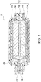
- FIG. 1 schematically illustrates an exemplary secondary lithium battery in the present invention.
- the secondary lithium battery 10 shown in FIG. 1 includes a positive electrode plate 16, a negative electrode 20, and an electrolytic solution 24.
- the positive electrode plate 16 is a lithium complex oxide sintered plate.
- the negative electrode 20 includes carbon and styrene butadiene rubber (SBR).
- the electrolytic solution 24 contains lithium borofluoride (LiBF 4 ) in a non-aqueous solvent composed of ⁇ -butyrolactone (GBL) and optional ethylene carbonate (EC).
- the positive electrode plate 16 which is a lithium complex oxide sintered plate, the negative electrode 20 containing carbon and styrene butadiene rubber (SBR), and the electrolytic solution 24 containing lithium borofluoride (LiBF 4 ) in the non-aqueous solvent composed of ⁇ -butyrolactone (GBL) and optional ethylene carbonate (EC) are selectively combined, thereby a secondary lithium battery having superior heat resistance can be provided.
- SBR styrene butadiene rubber
- EC ethylene carbonate
- hot lamination may be applied to incorporate a thin lithium battery into a low-profile device, such as a smart card, and reflow soldering may be used to mount a thin lithium battery on a printed wiring board. All of these procedures involve heating to a high temperature of 110°C or higher, and a conventional thin lithium battery with liquid electrolyte has insufficient heat resistance, resulting in swelling, breaking and increase in electrical resistance of the battery when the battery is heated to 110°C or higher.
- the secondary lithium battery 10 in the present invention has superior heat resistance: Even when heated to 110°C or higher, the battery does not swell or break and the electrical resistance of the battery does not increase.
- Such superior heat resistance is provided by selective combination of the specified positive electrode plate 16, negative electrode 20, and electrolytic solution 24 described above.
- the secondary lithium battery 10 may be mounted on a substrate through, preferably a process involving heating to 110°C or higher, more preferably a process involving heating by hot lamination or reflow soldering.
- a method of manufacturing a battery-incorporating device comprising a step of preparing a secondary lithium battery and a step of mounting the secondary lithium battery on a substrate through, preferably a process involving heating to 110°C or higher, more preferably a process involving heating by hot lamination or reflow soldering.
- the process involving heating is hot lamination and the battery-incorporating device is a battery-incorporating smart card.
- a heating temperature is preferably 110°C to less than 260°C, more preferably 110°C to less than 240°C, further more preferably 110°C to less than 220°C, particularly more preferably 110°C to less than 200°C, most preferably 110°C to less than 150°C.
- the positive electrode plate 16 is a lithium complex oxide sintered plate.
- the phrase "the positive electrode plate 16 is a sintered plate” indicates that the positive electrode plate 16 contains no binder because the binder disappears or burns off during firing even if the green sheet of the positive electrode contains the binder. Containing no binder in the positive electrode plate 16 has an advantage in that deterioration of the positive electrode due to the electrolytic solution can be avoided.
- a binder called polyvinylidene fluoride (PVDF) is widely used for a positive electrode in conventional lithium batteries, and this PVDF is highly soluble in ⁇ -butyrolactone (GBL) used as the electrolytic solution in the present invention, resulting in a loss in function of the binder.
- the positive electrode plate 16 used in the present invention is a sintered plate containing no binder, the problem as described above does not occur.
- Particularly preferred lithium complex oxide constituting the sintered plate is lithium cobaltate (typically, LiCoO 2 (hereinafter, it may be abbreviated as LCO)).
- LCO lithium complex oxide sintered plates or LCO sintered plates are known.
- the sintered plate disclosed in PTL 3 JP5587052B
- the sintered plate disclosed in PTL 3 JP5587052B
- the positive electrode plate 16 i.e, the lithium complex oxide sintered plate, includes a plurality of primary grains composed of lithium complex oxide, and is also an oriented positive electrode plate in which the plurality of primary grains are oriented at a mean orientation angle of more than 0° to 30° to a plate face of the positive electrode plate.
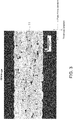
- FIG. 3 illustrates an example of a cross-sectional SEM image perpendicular to the plate face of the oriented positive electrode plate 16
- FIG. 4 illustrates an electron backscatter diffraction (EBSD) image on a cross-section perpendicular to the plate face of the oriented positive electrode plate 16.
- EBSD electron backscatter diffraction
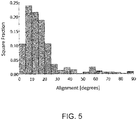
- FIG. 5 is an area-based histogram illustrating the distribution of orientation angles of the primary grains 11 in the EBSD image of FIG. 4 .
- the orientation angle of each primary grain 11 is determined by the shade of color, and a darker shade indicates a smaller orientation angle.
- the orientation angle is a tilt angle between the (003) plane of each primary grain 11 and a plate face.
- black portions inside the oriented positive electrode plate 16 indicate pores.
- the oriented positive electrode plate 16 is an oriented sintered plate composed of multiple primary grains 11 bonded to each other.
- Each primary grain 11 is mainly in a platy shape, and may be formed in, for example, a cuboid shape, a cubic shape, and a spherical shape.
- the cross-sectional shape of each primary grain 11 may be a rectangle, a polygon other than a rectangle, a circle, an ellipse, or any other complicated shape.
- Each primary grain 11 is composed of lithium complex oxide.
- the lithium complex oxide is an oxide represented by Li x MO 2 (0.05 ⁇ x ⁇ 1.10, M is at least one transition metal, and M typically contains at least one of Co, Ni and Mn).
- the lithium complex oxide has a layered rock salt structure.
- the layered rock salt structure is a crystal structure in which a lithium layer and a transition metal layer other than lithium are alternately stacked with an oxygen layer therebetween, i.e., a crystal structure in which a transition metal ion layer and a lithium single layer are alternately stacked with oxide ions therebetween (typically an ⁇ -NaFeO 2 structure, i.e., a structure in which transition metals and lithium metals are regularly disposed along the [111] axis of a cubic rock salt structure).
- ⁇ -NaFeO 2 structure i.e., a structure in which transition metals and lithium metals are regularly disposed along the [111] axis of a cubic rock salt structure.
- lithium complex oxides include LixCoO 2 (lithium cobaltate), LixNiO 2 (lithium nickelate), LixMnO 2 (lithium manganate), LixNiMnO 2 (lithium nickel manganate), LixNiCoO 2 (lithium nickel cobaltate), LixCoNiMnO 2 (lithium cobalt nickel manganate), LixCoMnO 2 (lithium cobalt manganate), and particularly preferably, LixCoO 2 (lithium cobaltate, typically LiCoO 2 ).
- the lithium complex oxide may contain at least one element selected from Mg, Al, Si, Ca, Ti, V, Cr, Fe, Cu, Zn, Ga, Ge, Sr, Y, Zr, Nb, Mo, Ag, Sn, Sb, Te, Ba., Bi, and W.
- a mean value of the orientation angles of primary grains 11, i.e., a mean orientation angle, is more than 0° to 30°.
- This angle range provides the following various advantages. Since each primary grain 11 greatly tilts from the thickness direction of the positive electrode plate, the adhesiveness between the individual primary grains can be improved. Due to this configuration, the lithium ion conductivity between one primary grain 11 and another primary grain 11 adjacent on two ends of the one primary grain 11 in the longitudinal direction can be improved, resulting in an improvement in high rate property. In addition, the high rate property can be further improved.
- the mean orientation angle of the primary grains 11 is determined by the following procedure. As shown in FIG. 4 , three horizontal lines which divide the oriented positive electrode plate 16 into four equal intervals in the plate thickness direction, and three vertical lines that divide it into four equal intervals in the plate face direction are drawn in an EBSD image that illustrates a 95 ⁇ m by 125 ⁇ m rectangular area observed at 1000-fold magnification.
- the mean orientation angle of the primary grains 11 is determined by arithmetically averaging the orientation angles of all the primary grains 11 that intersect at least one of the three horizontal lines and the three vertical lines.
- the mean orientation angle of the primary grains 11 is preferably 30° or less, and more preferably 25° or less from the viewpoint of a further improvement in high rate property.
- the mean orientation angle of the primary grains 11 is preferably 2° or more, and more preferably 5° or more from the viewpoint of a further improvement in high rate property.
- the orientation angle of each primary grain 11 may be widely distributed from 0° to 90°, and most of the orientation angles are preferably distributed in a region of more than 0° to 30°.
- the total area of primary grains 11 that have the orientation angle of more than 0° to 30° to the plate face of the oriented positive electrode plate 16 (hereinafter, referred to as low-angle primary grains) is preferably 70% or more, and more preferably 80% or more of the total area of the primary grains 11 (specifically, 30 primary grains 11 used in calculation of the mean orientation angle) included in the cross-section.
- the total area of the low-angle primary grains having an orientation angle of 20° or less is more preferably 50% or more of the total area of the 30 primary grains 11 used in the calculation of the mean orientation angle.
- the total area of the low-angle primary grains having an orientation angle of 10° or less is more preferably 15% or more of the total area of the 30 primary grains 11 used in the calculation of the mean orientation angle.
- each primary grain 11 is mainly platy
- the cross-section of each primary grain 11 respectively extends in a predetermined direction as shown in FIGS. 3 and 4 , and typically has a substantially rectangular shape.
- the total area of primary grains 11 that have an aspect ratio of 4 or more among the primary grains 11 included in the analyzed cross-section is preferably 70% or more, and more preferably 80% or more of the total area of the primary grains 11 (specifically, 30 primary grains 11 used in calculation of the mean orientation angle) included in the cross-section.
- the configuration shown in the EBSD image of FIG. 4 can increase the mutual adhesiveness between the primary grains 11, resulting in a further improvement of high rate property.
- the aspect ratio of the primary grains 11 is a value determined by dividing the maximum Feret diameter by the minimum Feret diameter of the primary grains 11.
- the maximum Feret diameter is the maximum distance between two parallel straight lines by which the primary grains 11 are sandwiched in the EBSD image from cross-sectional observation.
- the minimum Feret diameter is the minimum distance between two parallel straight lines by which the primary grains 11 are sandwiched.
- a plurality of primary grains constituting the oriented sintered plate preferably has a mean primary grain diameter of 5 ⁇ m or more.
- the 30 primary grains 11 used in the calculation of the mean orientation angle has a mean grain diameter of preferably 5 ⁇ m or more, more preferably 7 ⁇ m or more, and further more preferably 12 ⁇ m or more.
- the number of grain boundaries between the primary grains 11 thereby decreases in the direction where lithium ions are conducted, resulting in an increase in overall lithium ion conductivity and thus a further improvement in high rate property.
- the mean grain diameter of the primary grains 11 is a value determined by arithmetically averaging equivalent circle diameters of respective primary grains 11.
- the equivalent circle diameter indicates the diameter of a circle having the same area as each primary grain 11 in the EBSD image.
- the compactness of the oriented sintered plate constituting the oriented positive electrode plate 16 is preferably 70% or more, more preferably 80% or more, further more preferably 90% or more.
- the mutual adhesiveness thereby increases between the primary grains 11, resulting in a further improvement in high rate property.
- the compactness of the oriented sintered plate can be calculated by binarizing the SEM image resultant from the observation with a SEM at 1000-fold magnification after polishing of the cross-section of the positive electrode plate with a cross-section polisher (CP).
- the mean equivalent circle diameter of pores formed inside the oriented sintered plate may be preferably 8 ⁇ m or less. Smaller mean equivalent circle diameter of pores can further increase the mutual adhesiveness between the primary grains 11, resulting in a further improvement in high rate property.
- the mean equivalent circle diameter of pores is a value determined by arithmetically averaging equivalent circle diameters of 10 pores in the EBSD image.
- the equivalent circle diameter indicates the diameter of a circle having an area that is the same as that of each pore in the EBSD image.
- Each pore formed inside the oriented sintered plate may be an open pore connected to the outside of the oriented positive electrode plate 16, although each pore does not preferably penetrate the oriented positive electrode plate 16 and thereby may be a closed pore.
- the oriented positive electrode plate 16 has a thickness of preferably 30 ⁇ m or more, more preferably 40 ⁇ m or more, particularly more preferably 50 ⁇ m or more, most preferably 55 ⁇ m or more from the viewpoint of an increase in the active material capacity per unit area and an improvement in energy density of the secondary lithium battery 10.
- the oriented positive electrode plate 16 has a thickness of preferably less than 200 ⁇ m, more preferably 150 ⁇ m or less, further more preferably 120 ⁇ m or less, particularly more preferably 100 ⁇ m or less, most preferably 90 ⁇ m or less, 80 ⁇ m or less, or 70 ⁇ m or less from the viewpoint of restraint in deterioration of battery properties due to repeated charge/discharge cycles (particularly, due to an increase in electrical resistance).
- the oriented positive electrode plate has a dimension of preferably 5 mm by 5 mm square or more, more preferably 10 mm by 10 mm to 200 mm by 200 mm square, further more preferably 10 mm by 10 mm to 100 mm by 100 mm square.
- the oriented positive electrode plate has a dimension of preferably at least 25 mm 2 , more preferably 100 to 40,000 mm 2 , further more preferably 100 to 10,000 mm 2 .
- the negative electrode 20 includes carbon and styrene butadiene rubber (SBR).
- the carbon is a negative electrode active material
- the SBR is a binder.
- Examples of carbon include graphite, pyrolytic carbon, coke, fired resin, small mesophase spheres, and mesophase pitch, and preferred carbon is graphite.
- the graphite may be any of natural graphite and artificial graphite. Containing styrene butadiene rubber (SBR), which is a binder, in the negative electrode 20 is advantageous in avoiding deterioration of the negative electrode due to the electrolytic solution.
- SBR styrene butadiene rubber
- PVDF polyvinylidene fluoride
- GBL ⁇ -butyrolactone
- the negative electrode 20 preferably contains no binder other than SBR (e.g., PVDF).
- the electrolytic solution 24 is a non-aqueous solvent that contains lithium borofluoride (LiBF 4 ).
- the non-aqueous solvent may be a single solvent composed of ⁇ -butyrolactone (GBL) or a mixed solvent composed of ⁇ -butyrolactone (GBL) and ethylene carbonate (EC). Since the non-aqueous solvent contains ⁇ -butyrolactone (GBL), the boiling point is increased, and the heat resistance is greatly improved.
- the ratio by volume of EC:GBL in the non-aqueous solvent is preferably 0:1 to 1:1 (GBL ratio of 50 to 100% by volume), more preferably 0:1 to 1:1.5 (GBL ratio of 60 to 100% by volume), more preferably 0:1 to 1:2 (GBL ratio of 66.6 to 100% by volume), particularly more preferably 0:1 to 1:3 (GBL ratio of 75 to 100% by volume).
- Lithium borofluoride (LiBF 4 ) dissolved in a non-aqueous solvent is an electrolyte having high decomposition temperature, and also results in a significant improvement in heat resistance.
- the electrolytic solution 24 has a LiBF 4 concentration of preferably 0.5 to 2 mol/L, more preferably 0.6 to 1.9 mol/L, further more preferably 0.7 to 1.7 mol/L, particularly more preferably 0.8 to 1.5 mol/L.
- the electrolytic solution 24 further preferably contains vinylene carbonate (VC), and/or fluoroethylene carbonate (FEC) and/or vinyl ethylene carbonate (VEC) as an additive.
- VC and FEC each have superior heat resistance.
- Further addition of such an additive into the electrolytic solution 24 can form an SEI film having superior heat resistance on the surface of the negative electrode 20, resulting in a further improvement in heat resistance of the secondary lithium battery 10.
- the secondary lithium battery 10 is further preferably provided with a separator 18.
- the separator 18 is composed of preferably polyimide, polyester (e.g., polyethylene terephthalate (PET)) or cellulose, and more preferably polyimide.
- a separator composed of polyimide, polyester (e.g., polyethylene terephthalate (PET)) or cellulose has not only superior heat resistance as its own property, but high wettability to ⁇ -butyrolactone (GBL) different from a separator composed of polyolefin, such as polypropylene (PP) and polyethylene (PE), that is widely used and has inferior heat resistance.
- the electrolytic solution 24 containing GBL can thus sufficiently penetrate (without being repelled) into the separator 18.
- a particularly preferred separator is composed of polyimide.
- Polyimide separators are commercially available and have a greatly complicated microstructure, and thereby have an advantage in more effective prevention or delaying of the growth of dendritic lithium deposited during overcharge and thus short circuiting.
- cellulose separators are advantageous in less expensiveness than the polyimide separators.
- the secondary lithium battery 10 has a thickness of preferably 0.45 mm or less, more preferably 0.1 to 0.45 mm, further more preferably 0.2 to 0.45 mm, particularly more preferably 0.3 to 0.40 mm. Such thickness ranges can cause a thin lithium battery suitable for being incorporated into a low-profile device, such as a smart card.
- cell unit 12 and the electrolytic solution 24, which are components of the secondary lithium battery 10 are preferably wrapped and sealed with packaging films 26.
- the secondary lithium battery 10 is preferably in the form of a so-called film-packed battery.
- the cell unit 12 each includes a positive electrode plate 16, a separator 18, and a negative electrode 20, and typically further includes a positive electrode collector 14 and a negative electrode collector 22.
- the positive electrode collector 14 and the negative electrode collector 22 may be composed of any material, preferably copper foil.
- the positive electrode collector 14 is preferably provided with a positive electrode terminal 15 extending from the positive electrode collector 14, and the negative electrode collector 22 is preferably provided with a negative electrode terminal 23 extending from the negative electrode collector 22.
- FIG. 1 cell unit 12 and the electrolytic solution 24, which are components of the secondary lithium battery 10, are preferably wrapped and sealed with packaging films 26.
- the secondary lithium battery 10 is preferably in the form of a so-called film-packed battery.
- the cell unit 12 each includes a positive electrode plate 16, a separator 18, and a negative
- the secondary lithium battery 10 is illustrated as being a layered structure and a sealed structure having a certain amount of space to clearly show the existence of the electrolytic solution 24, however such a space is desired to be minimized in an actual battery.
- the outer edges of the secondary lithium battery 10 are sealed by thermal bonding of the packaging films 26 to each other. Sealing by thermal bonding is preferably performed with a heat bar (also referred to as a heating bar) generally used in heat sealing.
- the packaging film 26 may be a commercially available packaging film.
- the packaging film 26 has a thickness of preferably 20 to 160 ⁇ m, more preferably 40 to 120 ⁇ m, further more preferably 40 to 65 ⁇ m.
- the packaging film 26 is preferably a laminated film including a resin film and a metal foil, more preferably an aluminum-laminated film including a resin film and an aluminum foil.
- the laminated film is preferably provided with resin films on two faces of the metal foil, such as the aluminum foil.
- a resin film on one face of the metal foil (hereinafter, referred to as a surface protective film) be composed of a material having high reinforcing properties, such as nylon, polyamide, poly(ethylene terephthalate), polyimide, polytetrafluoroethylene, and polychlorotrifluoroethylene, and a resin film on the other face of the metal foil (hereinafter, referred to as a sealing resin film) be composed of a heat sealing material, such as polypropylene.
- a material having high reinforcing properties such as nylon, polyamide, poly(ethylene terephthalate), polyimide, polytetrafluoroethylene, and polychlorotrifluoroethylene
- a resin film on the other face of the metal foil (hereinafter, referred to as a sealing resin film) be composed of a heat sealing material, such as polypropylene.
- Aluminum-laminated films having such a layer structure composed of a surface protective film/an aluminum foil/a sealing resin film are commercially available for lithium batteries, and most of the sealing resin films in the commercially available aluminum-laminated film have a two-layer structure of polypropylene resin.
- this two-layer structure is composed of a main layer having a softening point of 150 to 160°C and an adhesive layer having a softening point of 130 to 140 °C disposed on the outside of the main layer.
- the adhesive layer having a softening point of 130 to 140°C has a lower softening point than the main layer, the adhesive layer can be readily softened or fluidized by heating, resulting in poor heat resistance. Accordingly, from the viewpoint of an increase in heat resistance of the secondary lithium battery 10, the following improvement a) or b) preferably should be achieved on the sealing resin film having the two-layer structure of polypropylene resin.
- At least one end of the positive electrode collector 14, the positive electrode terminal 15, the negative electrode collector 22, and the negative electrode terminal 23 may be covered with a protective tape.
- the covering can effectively prevent the breakage of the packaging film 26 due to burrs that may be formed at the edge of the cell unit.
- Preferred examples of the protective tape include a polyimide tape because of its superior heat resistance.
- An oriented positive electrode plate or an oriented sintered plate preferably used in the secondary lithium battery of the present invention may be produced by any process, although preferably produced through the following steps: (1) preparation of LiCoO 2 template grains, (2) preparation of matrix grains, (3) preparation of green sheet, and (4) production of oriented sintered plate.
- Co 3 O 4 raw material powder and Li 2 CO 3 raw material powder are mixed.
- the mixed powder is fired at 500 to 900°C for 1 to 20 hours to synthesize LiCoO 2 powder.
- the resultant LiCoO 2 powder is pulverized in a pot mill into a volume-based D50 grain diameter of 0.1 to 10 ⁇ m to give platy LiCoO 2 grains capable of conducting lithium ions parallel to the plate face.
- the resultant platy LiCoO 2 grains are in a state of being readily cleaved along cleavage planes.
- the LiCoO 2 grains are cleaved by disintegration to produce LiCoO 2 template grains.
- Such LiCoO 2 grains may also be produced through several processes, such as a disintegration process after the grain growth in a green sheet prepared from LiCoO 2 powder slurry, a flux process, a hydrothermal synthesis process, a single-crystal growth process using a melt, and a sol-gel process.
- the profile of primary grains 11 constituting the oriented positive electrode plate 16 can be controlled as follows.
- Co 3 O 4 raw material powder is used as matrix grains.
- the Co 3 O 4 raw material powder may have any volume-based D50 grain diameter, for example, 0.1 to 1.0 ⁇ m, and is preferably smaller than the volume-based D50 grain diameter of the LiCoO 2 template grains.
- the matrix grains can also be prepared through heat treatment of Co(OH) 2 raw material at 500 to 800°C for 1 to 10 hours. Co(OH) 2 grains or LiCoO 2 grains other than Co 3 O 4 . are used as the matrix grains.
- the profile of primary grains 11 constituting the oriented positive electrode plate 16 can be controlled as follows.
- LiCoO 2 template grains and matrix grains are mixed in a ratio of 100:3 to 3:97 to give a mixed powder.
- the mixed powder, a dispersion medium, a binder, a plasticizer, and a dispersant are stirred and defoamed under reduced pressure while mixing to prepare a slurry having a desired viscosity.
- the resultant slurry is then formed into a shaped material using a molding procedure capable of applying a shear force to the LiCoO 2 template grains. Through these steps, each primary grain 11 can be aligned to have a mean orientation angle of more than 0° to 30°.
- the molding procedure capable of applying a shear force to the LiCoO 2 template grains is preferably a doctor blade process. In the doctor blade process, the resultant slurry is formed on a PET film to prepare the shaped material, i.e., a green sheet.
- the profile of primary grains 11 constituting the oriented positive electrode plate 16 can be controlled as follows.
- the shaped material prepared from the slurry is placed on a zirconia setter and heated at 500 to 900°C for 1 to 10 hours (primary firing) to give a sintered plate as an intermediate.
- This sintered plate is sandwiched between lithium-containing sheets (e.g., Li 2 CO 3 -containing sheets), placed on a zirconia setter, and heated (secondary firing) to prepare a LiCoO 2 sintered plate.
- lithium-containing sheets e.g., Li 2 CO 3 -containing sheets
- a setter on which a sintered plate sandwiched between lithium-containing sheets is placed is disposed in an alumina sheath and fired at 700 to 850°C for 1 to 20 hours in the air, and then the resultant sintered plate is further sandwiched between lithium-containing sheets and fired at 750 to 900°C for 1 to 40 hours to produce a LiCoO 2 sintered plate.
- This firing step may be performed in two separate stages or in one stage. In a two-stage firing process, the firing temperature in the first stage is preferably lower than that in the second stage.
- the total amount of the lithium-containing sheet used in the secondary firing may be selected such that Li/Co ratio is 1.0, the Li/Co ratio being the molar ratio of Li content in the green sheet and the lithium-containing sheet to Co content in the green sheet.
- the profile of primary grains 11 constituting the oriented positive electrode plate 16 can be controlled as follows.
- a secondary lithium battery 10 in the form of a film-packed battery schematically shown in FIG. 1 was produced by the procedures as shown in FIGS. 2A and 2B .
- the details are as follows: A 90 ⁇ m-thick LiCoO 2 sintered plate (hereinafter referred to as an LCO sintered plate) was provided.
- the LCO sintered plate was manufactured in accordance with the method described above for manufacturing a lithium complex oxide sintered plate, and satisfied several preferred conditions for the lithium complex oxide sintered plate as described above.
- the sintered plate was cut with a laser processing tool into multiple positive electrode plates 16 each being a square of 10 mm by 10 mm.
- Two aluminum-laminated films (manufactured by Showa Denko Packaging Co., Ltd., a thickness of 61 ⁇ m, three-layer structure composed of a polypropylene film/an aluminum foil/a nylon film) were provided as packaging films 26.
- multiple positive electrode plates 16 were laterally disposed on one packaging film 26 with a positive electrode collector 14 (a copper foil having a thickness of 9 ⁇ m) therebetween to give a positive electrode assembly 17.
- the positive electrode collector 14 was fixed to one packaging film 26 with an adhesive.
- the positive electrode collector 14 was provided with a positive electrode terminal 15 welded to and extending from the positive electrode collector 14.
- a negative electrode 20 (a carbon layer having a thickness of 130 ⁇ m) was disposed on the other packaging film 26 with a negative electrode collector 22 (a copper foil having a thickness of 10 ⁇ m) therebetween to give a negative electrode assembly 19.
- the negative electrode collector 22 was fixed to the packaging film 26 with an adhesive.
- the negative electrode collector 22 was provided with a negative electrode terminal 23 welded to and extending from the negative electrode collector 22.
- the carbon layer, which is the negative electrode 20 was in the form of a coated layer containing a mixture of graphite as an active material and styrene butadiene rubber (SBR) as a binder.
- SBR styrene butadiene rubber
- a porous polyimide film (manufactured by Tokyo Ohka Kogyo Co., Ltd., a thickness of 23 ⁇ m, a porosity of 80%) was provided as a separator 18.
- the positive electrode assembly 17, the separator 18, and the negative electrode assembly 19 are stacked in sequence such that the positive electrode plate 16 and the negative electrode 20 face the separator 18 to produce a laminate 28 in which two outer surfaces were covered with packaging films 26 and the outer periphery of the packaging films 26 protruded from the outer edge of the cell unit 12.
- the cell unit 12 (the positive electrode collector 14, the positive electrode plate 16, the separator 18, the negative electrode 20, and the negative electrode collector 22) constructed in the laminate 28 had a thickness of 0.33 mm, and a rectangular shape with dimensions of 2.3 cm by 3.2 cm.
- the laminate was transferred into a glove box 38, and a gap was formed between a pair of packaging films 26 at one unsealed edge B remained in the laminate 28 in which the three edges A were sealed.
- An electrolytic solution 24 was injected from an injector 36 into the gap, and the edge B was then temporarily sealed with a simple sealer under a reduced pressure of 5 kPa.
- the electrolytic solution was prepared by dissolution of LiBF 4 in a concentration of 1.5 mol/L into a mixed solvent containing ethylene carbonate (EC) and ⁇ -butyrolactone (GBL) in a ratio of 1:3 (by volume).
- EC ethylene carbonate
- GBL ⁇ -butyrolactone
- a fresh edge B' formed by cutting off of the temporary sealed portion was sealed under a reduced pressure of 5 kPa in the glove box 38.
- This sealing was also performed by hot pressing of the outer periphery of the laminate 28 at 200°C and 1.5 MPa for 10 seconds and thermal fusion bonding of the packaging films 26 (aluminum-laminated films) to each other at the outer periphery.
- the edge B' was sealed between a pair of packaging films 26 to produce a secondary lithium battery 10 in the form of a film-packed battery.
- the secondary lithium battery 10 was retrieved from the glove box 38, and unnecessary portions on the outer periphery of the packaging film 26 were trimmed away to fix the shape as the secondary lithium battery 10.
- the secondary lithium battery 10 was completed in which the four outer edges of the cell unit 12 were sealed between a pair of packaging films 26 and the electrolytic solution 24 was injected.
- the resultant secondary lithium battery 10 was in a rectangular shape having dimensions of 38 mm by 27 mm, and had a thickness of 0.45 mm or less and a capacity of 30 mAh.
- the lithium secondary batteries prepared were heated at various temperatures (20°C, 100°C, 110°C, 120°C, or 150°C) shown in FIG.1 for 30 minutes and pressed at a pressure of 0.7 MPa in a hot press system, and the following properties were then evaluated.
- the heated lithium secondary batteries were visually observed to determine whether any change occurred in appearance of the battery. As shown in Table 1A, no change in appearance of the battery is observed at all the heating temperatures.
- the Electrical resistance of each heated secondary lithium battery was measured by an AC impedance method using an electrochemical measurement system SP-150 manufactured by BioLogic Science Instruments. The electrical resistance measured was calculated as a relative value where the resistance of the battery heated at 20°C was 1. The results are shown in Table 1A. No change in electrical resistance is observed in the batteries heated at all the temperatures compared with the battery heated at 20°C.
- Batteries were prepared and evaluated as in Example A1 except that a) a coated layer of a mixture of LiCoO 2 powder and polyvinylidene fluoride (PVDF) (hereinafter referred to as an LCO coated electrode) was used as the positive electrode instead of the LCO sintered plate, b) a mixed solvent of ethylene carbonate (EC) and ethyl methyl carbonate (EMC) in a ratio of 3:7 (volume ratio) containing 1 mol/L LiPF 6 was used as the electrolytic solution, and c) polyvinylidene fluoride (PVDF) was used as the negative electrode binder instead of SBR.
- Table 1A The results are shown in Table 1A.
- Batteries were prepared and evaluated as in Example A2 except that a mixed solvent of ethylene carbonate (EC) and diethyl carbonate (DEC) in a ratio of 3:7 (volume ratio) containing 1 mol/L LiPF 6 was used as the electrolytic solution.
- EC ethylene carbonate
- DEC diethyl carbonate
- Table 1A The results are shown in Table 1A.
- Batteries were prepared and evaluated as in Example A1 except that a) a mixed solvent of ethylene carbonate (EC) and ethyl methyl carbonate (EMC) in a ratio of 3:7 (volume ratio) containing 1 mol/L LiPF 6 was used as the electrolytic solution, and b) polyvinylidene fluoride (PVDF) was used as the negative electrode binder instead of SBR.
- EC ethylene carbonate
- EMC ethyl methyl carbonate
- PVDF polyvinylidene fluoride
- Batteries were prepared and evaluated as in Example A4 except that a mixed solvent of ethylene carbonate (EC) and diethyl carbonate (DEC) in a ratio of 3:7 (volume ratio) containing 1 mol/L LiPF 6 was used as the electrolytic solution.
- EC ethylene carbonate
- DEC diethyl carbonate
- Table 1A The results are shown in Table 1A.
- Batteries were prepared and evaluated as in Example A1 except that a mixed solvent of ethylene carbonate (EC) and ethyl methyl carbonate (EMC) in a ratio of 3:7 (volume ratio) containing 1 mol/L LiPF 6 was used as the electrolytic solution.
- EC ethylene carbonate
- EMC ethyl methyl carbonate
- Batteries were prepared and evaluated as in Example A1 except that a mixed solvent of ethylene carbonate (EC) and diethyl carbonate (DEC) in a ratio of 3:7 (volume ratio) containing 1 mol/L LiPF 6 was used as the electrolytic solution.
- EC ethylene carbonate
- DEC diethyl carbonate
- Table 1A The results are shown in Table 1A.
- Batteries were prepared and evaluated as in Example A1 except that a) a coated layer of a mixture of LiCoO 2 powder and polyvinylidene fluoride (PVDF) (i.e., an LCO coated electrode) was used as the positive electrode instead of the LCO sintered plate, and b) polyvinylidene fluoride (PVDF) was used as the negative electrode binder instead of SBR.
- PVDF polyvinylidene fluoride
- Batteries were prepared and evaluated as in Example A1 except that a coated layer of a mixture of LiCoO 2 powder and polyvinylidene fluoride (PVDF) (i.e., an LCO coated electrode) was used as the positive electrode instead of the LCO sintered plate.
- PVDF polyvinylidene fluoride
- PVDF polyvinylidene fluoride
- Example A10 Batteries were prepared and evaluated as in Example A10 except that a mixed solvent of propylene carbonate (PC) and ⁇ -butyrolactone (GBL) in a ratio of 1:3 (volume ratio) containing 1.5 mol/L LiBF 4 was used as the electrolytic solution.
- PC propylene carbonate
- GBL ⁇ -butyrolactone
- Example A1 Batteries were prepared and evaluated as in Example A1 except that a mixed solvent of propylene carbonate (PC) and ⁇ -butyrolactone (GBL) in a ratio of 1:3 (volume ratio) containing 1.5 mol/L LiBF 4 was used as the electrolytic solution.
- PC propylene carbonate
- GBL ⁇ -butyrolactone
Landscapes
- Chemical & Material Sciences (AREA)
- Electrochemistry (AREA)
- General Chemical & Material Sciences (AREA)
- Chemical Kinetics & Catalysis (AREA)
- Engineering & Computer Science (AREA)
- Manufacturing & Machinery (AREA)
- Inorganic Chemistry (AREA)
- Materials Engineering (AREA)
- Physics & Mathematics (AREA)
- Condensed Matter Physics & Semiconductors (AREA)
- General Physics & Mathematics (AREA)
- Secondary Cells (AREA)
- Battery Electrode And Active Subsutance (AREA)
- Cell Separators (AREA)
- Battery Mounting, Suspending (AREA)
Abstract
Description
- The present invention relates to a secondary lithium battery and a method for manufacturing a battery-incorporating device.
- In recent years, battery-incorporating smart cards have been put into practical use. Examples of smart cards that incorporate primary batteries include credit cards provided with a one-time password display function. Examples of smart cards that incorporate secondary batteries include cards provided with fingerprint authentication and wireless communication functions, the cards having ICs for wireless communication, ASICs for fingerprint analysis, and fingerprint sensors. Batteries for smart cards generally have several requirements, such as a thickness of less than 0.45 mm, high battery capacity, low electrical resistance, high bending resistance, and high resistance to process temperature of batteries.
- For such applications, thin lithium batteries with liquid electrolyte have been proposed. For example, PTL 1 (
JP2013-97931A JP2012-209124A - Powder-dispersed positive electrodes are widely known as layers of positive electrode active material for lithium secondary batteries (also referred to as lithium ion secondary batteries), and are usually produced by kneading and molding particles of lithium complex oxide (typically, lithium-transition metal oxide) and additives, such as binders or conductive agents. Such powder-dispersed positive electrodes contain a relatively large amount (e.g., about 10% by weight) of binder that does not contribute to the capacity of battery, resulting in a low packing density of the positive electrode active material, i.e., lithium complex oxide. Accordingly, the powder-dispersed positive electrode should be further improved from the viewpoint of the capacity and charge/discharge efficiency. Some attempts have been made to improve the capacity and charge/discharge efficiency with positive electrodes or layers of positive electrode active material composed of sintered plate of lithium complex oxide. In this case, the positive electrode or the layer of positive electrode active material contains no binder; hence, high capacity and satisfactory charge/discharge efficiency can be expected due to a high packing density of lithium complex oxide. For example, PTL 3 (
JP5587052B - PTL 4 (JPH10-312825A) discloses a secondary lithium battery including a mixed solvent consisting of 10 to 40% by volume of ethylene carbonate and 60 to 90% by volume of γ-butyrolactone as a non-aqueous solvent for an electrolytic solution in order to improve low-temperature discharge property.
-
- PTL1:
JP2013-97931A - PTL2:
JP2012-209124A - PTL3:
JP5587052B - PTL4:
JPH10-312825A - A hot lamination process may be applied to production of cards. The production of cards by a hot lamination process is performed, for example, through pressing of a card substrate and a resin film at a temperature of 110°C or higher (e.g., 120 to 150°C) and bonding to each other. Accordingly, the use of hot lamination process is advantageous in a method of incorporating a thin lithium battery in a low-profile device, such as a smart card. In this case, it is conceivable that a thin lithium battery and a protective film are sequentially stacked on a card substrate and pressed at a high temperature of 110°C or more. However, a conventional thin lithium battery with liquid electrolyte has insufficient heat resistance, resulting in swelling, breaking and increase in electrical resistance of the battery when the battery is heated to 110°C or more. In a procedure of mounting a thin lithium battery on a printed wiring board, a reflow soldering process may be used. This process also involves heating to a high temperature, thereby a similar problem as described above may occur.
- The present inventors have now found that by selective combination of a positive electrode plate which is a lithium complex oxide sintered plate, a negative electrode containing carbon and styrene butadiene rubber (SBR), and an electrolytic solution containing lithium borofluoride (LiBF4) in a non-aqueous solvent composed of γ-butyrolactone (GBL) and optional ethylene carbonate (EC), it is possible to provide a secondary lithium battery having superior heat resistance.
- Accordingly, an object of the present invention is to provide a secondary lithium battery having superior heat resistance.
- According to an aspect of the present invention, there is provided a secondary lithium battery, comprising:
- a positive electrode plate that is a lithium complex oxide sintered plate;
- a negative electrode containing carbon and styrene butadiene rubber (SBR); and
- an electrolytic solution containing lithium borofluoride (LiBF4) in a non-aqueous solvent composed of γ-butyrolactone (GBL), or composed of γ-butyrolactone (GBL) and ethylene carbonate (EC).
- According to another aspect of the present invention, there is provided a method for manufacturing a battery-incorporating device, comprising the steps of:
- providing the secondary lithium battery; and
- mounting the secondary lithium battery on a substrate by a process involving heating at 110°C to lower than 260°C.
-
-
FIG. 1 is a schematic cross-sectional view of an exemplary secondary lithium battery in the present invention. -
FIG. 2A is a view illustrating the former steps of an exemplary manufacturing process of a secondary lithium battery. -
FIG. 2B is a view illustrating the latter steps of an exemplary manufacturing process of a secondary lithium battery subsequent to the steps illustrated inFIG. 2A . The right end ofFIG. 2B includes a photograph of a film-packed battery. -
FIG. 3 is an SEM image illustrating an exemplary cross-section perpendicular to a plate face of an oriented positive electrode plate. -
FIG. 4 is an EBSD image of a cross-section of the oriented positive electrode plate shown inFIG 3 . -
FIG. 5 is an area-based histogram illustrating the distribution of orientation angles of primary grains in the EBSD image ofFIG. 4 . -
FIG. 1 schematically illustrates an exemplary secondary lithium battery in the present invention. Thesecondary lithium battery 10 shown inFIG. 1 includes apositive electrode plate 16, anegative electrode 20, and anelectrolytic solution 24. Thepositive electrode plate 16 is a lithium complex oxide sintered plate. Thenegative electrode 20 includes carbon and styrene butadiene rubber (SBR). Theelectrolytic solution 24 contains lithium borofluoride (LiBF4) in a non-aqueous solvent composed of γ-butyrolactone (GBL) and optional ethylene carbonate (EC). As described above, thepositive electrode plate 16, which is a lithium complex oxide sintered plate, thenegative electrode 20 containing carbon and styrene butadiene rubber (SBR), and theelectrolytic solution 24 containing lithium borofluoride (LiBF4) in the non-aqueous solvent composed of γ-butyrolactone (GBL) and optional ethylene carbonate (EC) are selectively combined, thereby a secondary lithium battery having superior heat resistance can be provided. Although multiple pieces ofpositive electrode plates 16 are shown inFIG. 1 , one piece ofpositive electrode plate 16 that is not divided into multiple pieces may be used in the present invention. - As described above, it is conceivable that hot lamination may be applied to incorporate a thin lithium battery into a low-profile device, such as a smart card, and reflow soldering may be used to mount a thin lithium battery on a printed wiring board. All of these procedures involve heating to a high temperature of 110°C or higher, and a conventional thin lithium battery with liquid electrolyte has insufficient heat resistance, resulting in swelling, breaking and increase in electrical resistance of the battery when the battery is heated to 110°C or higher. In contrast, the
secondary lithium battery 10 in the present invention has superior heat resistance: Even when heated to 110°C or higher, the battery does not swell or break and the electrical resistance of the battery does not increase. Such superior heat resistance is provided by selective combination of the specifiedpositive electrode plate 16,negative electrode 20, andelectrolytic solution 24 described above. - Accordingly, the
secondary lithium battery 10 may be mounted on a substrate through, preferably a process involving heating to 110°C or higher, more preferably a process involving heating by hot lamination or reflow soldering. In other words, according to another preferred embodiment of the present invention, a method of manufacturing a battery-incorporating device is provided comprising a step of preparing a secondary lithium battery and a step of mounting the secondary lithium battery on a substrate through, preferably a process involving heating to 110°C or higher, more preferably a process involving heating by hot lamination or reflow soldering. In this embodiment, it is particularly preferred that the process involving heating is hot lamination and the battery-incorporating device is a battery-incorporating smart card. In any embodiment, a heating temperature is preferably 110°C to less than 260°C, more preferably 110°C to less than 240°C, further more preferably 110°C to less than 220°C, particularly more preferably 110°C to less than 200°C, most preferably 110°C to less than 150°C. - The
positive electrode plate 16 is a lithium complex oxide sintered plate. The phrase "thepositive electrode plate 16 is a sintered plate" indicates that thepositive electrode plate 16 contains no binder because the binder disappears or burns off during firing even if the green sheet of the positive electrode contains the binder. Containing no binder in thepositive electrode plate 16 has an advantage in that deterioration of the positive electrode due to the electrolytic solution can be avoided. For example, as disclosed in PTLs 1, 2, and 4, a binder called polyvinylidene fluoride (PVDF) is widely used for a positive electrode in conventional lithium batteries, and this PVDF is highly soluble in γ-butyrolactone (GBL) used as the electrolytic solution in the present invention, resulting in a loss in function of the binder. In this regard, since thepositive electrode plate 16 used in the present invention is a sintered plate containing no binder, the problem as described above does not occur. Particularly preferred lithium complex oxide constituting the sintered plate is lithium cobaltate (typically, LiCoO2 (hereinafter, it may be abbreviated as LCO)). Various lithium complex oxide sintered plates or LCO sintered plates are known. For example, the sintered plate disclosed in PTL 3 (JP5587052B - According to a preferred embodiment of the present invention, the
positive electrode plate 16, i.e, the lithium complex oxide sintered plate, includes a plurality of primary grains composed of lithium complex oxide, and is also an oriented positive electrode plate in which the plurality of primary grains are oriented at a mean orientation angle of more than 0° to 30° to a plate face of the positive electrode plate.FIG. 3 illustrates an example of a cross-sectional SEM image perpendicular to the plate face of the orientedpositive electrode plate 16, andFIG. 4 illustrates an electron backscatter diffraction (EBSD) image on a cross-section perpendicular to the plate face of the orientedpositive electrode plate 16.FIG. 5 is an area-based histogram illustrating the distribution of orientation angles of theprimary grains 11 in the EBSD image ofFIG. 4 . In the EBSD image shown inFIG. 4 , discontinuity of the crystal orientation can be observed. InFIG. 4 , the orientation angle of eachprimary grain 11 is determined by the shade of color, and a darker shade indicates a smaller orientation angle. The orientation angle is a tilt angle between the (003) plane of eachprimary grain 11 and a plate face. InFIGS. 3 and4 , black portions inside the orientedpositive electrode plate 16 indicate pores. - The oriented
positive electrode plate 16 is an oriented sintered plate composed of multipleprimary grains 11 bonded to each other. Eachprimary grain 11 is mainly in a platy shape, and may be formed in, for example, a cuboid shape, a cubic shape, and a spherical shape. The cross-sectional shape of eachprimary grain 11 may be a rectangle, a polygon other than a rectangle, a circle, an ellipse, or any other complicated shape. - Each
primary grain 11 is composed of lithium complex oxide. The lithium complex oxide is an oxide represented by LixMO2 (0.05<x<1.10, M is at least one transition metal, and M typically contains at least one of Co, Ni and Mn). The lithium complex oxide has a layered rock salt structure. The layered rock salt structure is a crystal structure in which a lithium layer and a transition metal layer other than lithium are alternately stacked with an oxygen layer therebetween, i.e., a crystal structure in which a transition metal ion layer and a lithium single layer are alternately stacked with oxide ions therebetween (typically an α-NaFeO2 structure, i.e., a structure in which transition metals and lithium metals are regularly disposed along the [111] axis of a cubic rock salt structure). Examples of lithium complex oxides include LixCoO2 (lithium cobaltate), LixNiO2 (lithium nickelate), LixMnO2 (lithium manganate), LixNiMnO2 (lithium nickel manganate), LixNiCoO2 (lithium nickel cobaltate), LixCoNiMnO2 (lithium cobalt nickel manganate), LixCoMnO2 (lithium cobalt manganate), and particularly preferably, LixCoO2 (lithium cobaltate, typically LiCoO2). The lithium complex oxide may contain at least one element selected from Mg, Al, Si, Ca, Ti, V, Cr, Fe, Cu, Zn, Ga, Ge, Sr, Y, Zr, Nb, Mo, Ag, Sn, Sb, Te, Ba., Bi, and W. - As shown in
FIGS. 4 and5 , a mean value of the orientation angles ofprimary grains 11, i.e., a mean orientation angle, is more than 0° to 30°. This angle range provides the following various advantages. Since eachprimary grain 11 greatly tilts from the thickness direction of the positive electrode plate, the adhesiveness between the individual primary grains can be improved. Due to this configuration, the lithium ion conductivity between oneprimary grain 11 and anotherprimary grain 11 adjacent on two ends of the oneprimary grain 11 in the longitudinal direction can be improved, resulting in an improvement in high rate property. In addition, the high rate property can be further improved. This further improvement is caused by smooth intercalation/deintercalation of lithium ions in the orientedpositive electrode 16, because expansion and contraction of the orientedpositive electrode plate 16 proceeds more dominantly in the thickness direction than in the plate face direction and thereby lithium ions can intercalate and deintercalate smoothly. - The mean orientation angle of the
primary grains 11 is determined by the following procedure. As shown inFIG. 4 , three horizontal lines which divide the orientedpositive electrode plate 16 into four equal intervals in the plate thickness direction, and three vertical lines that divide it into four equal intervals in the plate face direction are drawn in an EBSD image that illustrates a 95 µm by 125 µm rectangular area observed at 1000-fold magnification. The mean orientation angle of theprimary grains 11 is determined by arithmetically averaging the orientation angles of all theprimary grains 11 that intersect at least one of the three horizontal lines and the three vertical lines. The mean orientation angle of theprimary grains 11 is preferably 30° or less, and more preferably 25° or less from the viewpoint of a further improvement in high rate property. The mean orientation angle of theprimary grains 11 is preferably 2° or more, and more preferably 5° or more from the viewpoint of a further improvement in high rate property. - As shown in
FIG. 5 , the orientation angle of eachprimary grain 11 may be widely distributed from 0° to 90°, and most of the orientation angles are preferably distributed in a region of more than 0° to 30°. In other words, when the cross-section of the oriented sintered plate constituting the orientedpositive electrode plate 16 is analyzed in the EBSD image, the total area ofprimary grains 11 that have the orientation angle of more than 0° to 30° to the plate face of the oriented positive electrode plate 16 (hereinafter, referred to as low-angle primary grains) is preferably 70% or more, and more preferably 80% or more of the total area of the primary grains 11 (specifically, 30primary grains 11 used in calculation of the mean orientation angle) included in the cross-section. This configuration can increase the proportion of theprimary grains 11 having higher mutual adhesiveness, thereby high rate property can be further improved. In addition, the total area of the low-angle primary grains having an orientation angle of 20° or less is more preferably 50% or more of the total area of the 30primary grains 11 used in the calculation of the mean orientation angle. Furthermore, the total area of the low-angle primary grains having an orientation angle of 10° or less is more preferably 15% or more of the total area of the 30primary grains 11 used in the calculation of the mean orientation angle. - Since each
primary grain 11 is mainly platy, the cross-section of eachprimary grain 11 respectively extends in a predetermined direction as shown inFIGS. 3 and4 , and typically has a substantially rectangular shape. In other words, when the cross-section of the oriented sintered plate is analyzed in the EBSD image, the total area ofprimary grains 11 that have an aspect ratio of 4 or more among theprimary grains 11 included in the analyzed cross-section is preferably 70% or more, and more preferably 80% or more of the total area of the primary grains 11 (specifically, 30primary grains 11 used in calculation of the mean orientation angle) included in the cross-section. In detail, the configuration shown in the EBSD image ofFIG. 4 can increase the mutual adhesiveness between theprimary grains 11, resulting in a further improvement of high rate property. The aspect ratio of theprimary grains 11 is a value determined by dividing the maximum Feret diameter by the minimum Feret diameter of theprimary grains 11. The maximum Feret diameter is the maximum distance between two parallel straight lines by which theprimary grains 11 are sandwiched in the EBSD image from cross-sectional observation. The minimum Feret diameter is the minimum distance between two parallel straight lines by which theprimary grains 11 are sandwiched. - A plurality of primary grains constituting the oriented sintered plate preferably has a mean primary grain diameter of 5 µm or more. Specifically, the 30
primary grains 11 used in the calculation of the mean orientation angle has a mean grain diameter of preferably 5 µm or more, more preferably 7 µm or more, and further more preferably 12 µm or more. The number of grain boundaries between theprimary grains 11 thereby decreases in the direction where lithium ions are conducted, resulting in an increase in overall lithium ion conductivity and thus a further improvement in high rate property. The mean grain diameter of theprimary grains 11 is a value determined by arithmetically averaging equivalent circle diameters of respectiveprimary grains 11. The equivalent circle diameter indicates the diameter of a circle having the same area as eachprimary grain 11 in the EBSD image. - The compactness of the oriented sintered plate constituting the oriented
positive electrode plate 16 is preferably 70% or more, more preferably 80% or more, further more preferably 90% or more. The mutual adhesiveness thereby increases between theprimary grains 11, resulting in a further improvement in high rate property. The compactness of the oriented sintered plate can be calculated by binarizing the SEM image resultant from the observation with a SEM at 1000-fold magnification after polishing of the cross-section of the positive electrode plate with a cross-section polisher (CP). The mean equivalent circle diameter of pores formed inside the oriented sintered plate may be preferably 8 µm or less. Smaller mean equivalent circle diameter of pores can further increase the mutual adhesiveness between theprimary grains 11, resulting in a further improvement in high rate property. The mean equivalent circle diameter of pores is a value determined by arithmetically averaging equivalent circle diameters of 10 pores in the EBSD image. The equivalent circle diameter indicates the diameter of a circle having an area that is the same as that of each pore in the EBSD image. Each pore formed inside the oriented sintered plate may be an open pore connected to the outside of the orientedpositive electrode plate 16, although each pore does not preferably penetrate the orientedpositive electrode plate 16 and thereby may be a closed pore. - The oriented
positive electrode plate 16 has a thickness of preferably 30 µm or more, more preferably 40 µm or more, particularly more preferably 50 µm or more, most preferably 55 µm or more from the viewpoint of an increase in the active material capacity per unit area and an improvement in energy density of thesecondary lithium battery 10. Although the upper limit of the thickness is not particularly limited, the orientedpositive electrode plate 16 has a thickness of preferably less than 200 µm, more preferably 150 µm or less, further more preferably 120 µm or less, particularly more preferably 100 µm or less, most preferably 90 µm or less, 80 µm or less, or 70 µm or less from the viewpoint of restraint in deterioration of battery properties due to repeated charge/discharge cycles (particularly, due to an increase in electrical resistance). In addition, the oriented positive electrode plate has a dimension of preferably 5 mm by 5 mm square or more, more preferably 10 mm by 10 mm to 200 mm by 200 mm square, further more preferably 10 mm by 10 mm to 100 mm by 100 mm square. In another expression, the oriented positive electrode plate has a dimension of preferably at least 25 mm2, more preferably 100 to 40,000 mm2, further more preferably 100 to 10,000 mm2. - The
negative electrode 20 includes carbon and styrene butadiene rubber (SBR). In detail, the carbon is a negative electrode active material, and the SBR is a binder. Examples of carbon include graphite, pyrolytic carbon, coke, fired resin, small mesophase spheres, and mesophase pitch, and preferred carbon is graphite. The graphite may be any of natural graphite and artificial graphite. Containing styrene butadiene rubber (SBR), which is a binder, in thenegative electrode 20 is advantageous in avoiding deterioration of the negative electrode due to the electrolytic solution. For example, as disclosed in PTL 4, a binder called polyvinylidene fluoride (PVDF) is widely used in a negative electrode of a conventional lithium battery, and this PVDF is greatly soluble in γ-butyrolactone (GBL) used in the present invention and loses its function as a binder. In this regard, since the styrene butadiene rubber (SBR) barely soluble in GBL is selectively applied in thenegative electrode 20 used in the present invention, the problem as described above does not occur. Accordingly, thenegative electrode 20 preferably contains no binder other than SBR (e.g., PVDF). - The
electrolytic solution 24 is a non-aqueous solvent that contains lithium borofluoride (LiBF4). The non-aqueous solvent may be a single solvent composed of γ-butyrolactone (GBL) or a mixed solvent composed of γ-butyrolactone (GBL) and ethylene carbonate (EC). Since the non-aqueous solvent contains γ-butyrolactone (GBL), the boiling point is increased, and the heat resistance is greatly improved. From this viewpoint, the ratio by volume of EC:GBL in the non-aqueous solvent is preferably 0:1 to 1:1 (GBL ratio of 50 to 100% by volume), more preferably 0:1 to 1:1.5 (GBL ratio of 60 to 100% by volume), more preferably 0:1 to 1:2 (GBL ratio of 66.6 to 100% by volume), particularly more preferably 0:1 to 1:3 (GBL ratio of 75 to 100% by volume). Lithium borofluoride (LiBF4) dissolved in a non-aqueous solvent is an electrolyte having high decomposition temperature, and also results in a significant improvement in heat resistance. Theelectrolytic solution 24 has a LiBF4 concentration of preferably 0.5 to 2 mol/L, more preferably 0.6 to 1.9 mol/L, further more preferably 0.7 to 1.7 mol/L, particularly more preferably 0.8 to 1.5 mol/L. - The
electrolytic solution 24 further preferably contains vinylene carbonate (VC), and/or fluoroethylene carbonate (FEC) and/or vinyl ethylene carbonate (VEC) as an additive. VC and FEC each have superior heat resistance. Further addition of such an additive into theelectrolytic solution 24 can form an SEI film having superior heat resistance on the surface of thenegative electrode 20, resulting in a further improvement in heat resistance of thesecondary lithium battery 10. - The
secondary lithium battery 10 is further preferably provided with aseparator 18. Theseparator 18 is composed of preferably polyimide, polyester (e.g., polyethylene terephthalate (PET)) or cellulose, and more preferably polyimide. A separator composed of polyimide, polyester (e.g., polyethylene terephthalate (PET)) or cellulose has not only superior heat resistance as its own property, but high wettability to γ-butyrolactone (GBL) different from a separator composed of polyolefin, such as polypropylene (PP) and polyethylene (PE), that is widely used and has inferior heat resistance. Theelectrolytic solution 24 containing GBL can thus sufficiently penetrate (without being repelled) into theseparator 18. As a result, the heat resistance of thesecondary lithium battery 10 can be further improved. A particularly preferred separator is composed of polyimide. Polyimide separators are commercially available and have a greatly complicated microstructure, and thereby have an advantage in more effective prevention or delaying of the growth of dendritic lithium deposited during overcharge and thus short circuiting. In contrast, cellulose separators are advantageous in less expensiveness than the polyimide separators. - The
secondary lithium battery 10 has a thickness of preferably 0.45 mm or less, more preferably 0.1 to 0.45 mm, further more preferably 0.2 to 0.45 mm, particularly more preferably 0.3 to 0.40 mm. Such thickness ranges can cause a thin lithium battery suitable for being incorporated into a low-profile device, such as a smart card. - As shown in
FIG. 1 ,cell unit 12 and theelectrolytic solution 24, which are components of thesecondary lithium battery 10, are preferably wrapped and sealed withpackaging films 26. In other words, thesecondary lithium battery 10 is preferably in the form of a so-called film-packed battery. In this battery, thecell unit 12 each includes apositive electrode plate 16, aseparator 18, and anegative electrode 20, and typically further includes apositive electrode collector 14 and anegative electrode collector 22. Thepositive electrode collector 14 and thenegative electrode collector 22 may be composed of any material, preferably copper foil. Thepositive electrode collector 14 is preferably provided with apositive electrode terminal 15 extending from thepositive electrode collector 14, and thenegative electrode collector 22 is preferably provided with anegative electrode terminal 23 extending from thenegative electrode collector 22. InFIG. 1 , thesecondary lithium battery 10 is illustrated as being a layered structure and a sealed structure having a certain amount of space to clearly show the existence of theelectrolytic solution 24, however such a space is desired to be minimized in an actual battery. The outer edges of thesecondary lithium battery 10 are sealed by thermal bonding of thepackaging films 26 to each other. Sealing by thermal bonding is preferably performed with a heat bar (also referred to as a heating bar) generally used in heat sealing. - The
packaging film 26 may be a commercially available packaging film. Thepackaging film 26 has a thickness of preferably 20 to 160 µm, more preferably 40 to 120 µm, further more preferably 40 to 65 µm. Thepackaging film 26 is preferably a laminated film including a resin film and a metal foil, more preferably an aluminum-laminated film including a resin film and an aluminum foil. The laminated film is preferably provided with resin films on two faces of the metal foil, such as the aluminum foil. In this case, it is preferred that a resin film on one face of the metal foil (hereinafter, referred to as a surface protective film) be composed of a material having high reinforcing properties, such as nylon, polyamide, poly(ethylene terephthalate), polyimide, polytetrafluoroethylene, and polychlorotrifluoroethylene, and a resin film on the other face of the metal foil (hereinafter, referred to as a sealing resin film) be composed of a heat sealing material, such as polypropylene. Aluminum-laminated films having such a layer structure composed of a surface protective film/an aluminum foil/a sealing resin film are commercially available for lithium batteries, and most of the sealing resin films in the commercially available aluminum-laminated film have a two-layer structure of polypropylene resin. In general, this two-layer structure is composed of a main layer having a softening point of 150 to 160°C and an adhesive layer having a softening point of 130 to 140 °C disposed on the outside of the main layer. However, since the adhesive layer having a softening point of 130 to 140°C has a lower softening point than the main layer, the adhesive layer can be readily softened or fluidized by heating, resulting in poor heat resistance. Accordingly, from the viewpoint of an increase in heat resistance of thesecondary lithium battery 10, the following improvement a) or b) preferably should be achieved on the sealing resin film having the two-layer structure of polypropylene resin. - a) A single-layer sealing resin film having only a main layer without an adhesive layer is used. This single-layer structure does not include an adhesive layer having a softening point of 130 to 140°C, thereby improving heat resistance. In this case, the main layer having a softening point of 150 to 160°C also serves as the adhesive layer.
- b) A heat-resistant polypropylene film having a higher softening temperature is used as a main layer without use of an adhesive layer. A known heat-resistant polypropylene film has a high softening temperature of 160 to 170°C, and a single-layer structure of such a heat-resistant polypropylene film is used as the sealing resin film, thereby achieving the highest level of heat resistance among the polypropylene films.
- In order to prevent the
packaging film 26 from being broken in a hot-pressing process, such as hot lamination, at least one end of thepositive electrode collector 14, thepositive electrode terminal 15, thenegative electrode collector 22, and thenegative electrode terminal 23 may be covered with a protective tape. The covering can effectively prevent the breakage of thepackaging film 26 due to burrs that may be formed at the edge of the cell unit. Preferred examples of the protective tape include a polyimide tape because of its superior heat resistance. - An oriented positive electrode plate or an oriented sintered plate preferably used in the secondary lithium battery of the present invention may be produced by any process, although preferably produced through the following steps: (1) preparation of LiCoO2 template grains, (2) preparation of matrix grains, (3) preparation of green sheet, and (4) production of oriented sintered plate.
- Co3O4 raw material powder and Li2CO3 raw material powder are mixed. The mixed powder is fired at 500 to 900°C for 1 to 20 hours to synthesize LiCoO2 powder. The resultant LiCoO2 powder is pulverized in a pot mill into a volume-based D50 grain diameter of 0.1 to 10 µm to give platy LiCoO2 grains capable of conducting lithium ions parallel to the plate face. The resultant platy LiCoO2 grains are in a state of being readily cleaved along cleavage planes. The LiCoO2 grains are cleaved by disintegration to produce LiCoO2 template grains. Such LiCoO2 grains may also be produced through several processes, such as a disintegration process after the grain growth in a green sheet prepared from LiCoO2 powder slurry, a flux process, a hydrothermal synthesis process, a single-crystal growth process using a melt, and a sol-gel process.
- In this step, the profile of
primary grains 11 constituting the orientedpositive electrode plate 16 can be controlled as follows. - Adjustment of at least one of the aspect ratio and the grain diameter of LiCoO2 template grains can control the total area rate of the low-angle primary grains having an orientation angle of more than 0° to 30°. Specifically, a higher aspect ratio of LiCoO2 template grains and a larger grain diameter of LiCoO2 template grains can increase the total area rate of the low-angle primary grains. The aspect ratio and the grain diameter of the LiCoO2 template grains, respectively, can be controlled by adjustment of at least one of the grain diameters of the Co3O4 raw material powder and the Li2CO3 raw material powder, pulverization conditions (e.g., pulverizing time, pulverizing energy, and pulverizing procedure), and classification conditions after the pulverization.
- Adjustment of the aspect ratio of LiCoO2 template grains can control the total area rate of the
primary grains 11 having an aspect ratio of 4 or more. Specifically, higher aspect ratio of LiCoO2 template grains can increase the total area rate of theprimary grains 11 having an aspect ratio of 4 or more. The procedures of adjusting the aspect ratio of the LiCoO2 template grains are as described above. - Adjustment of the grain diameter of LiCoO2 template grains can control a mean grain diameter of the
primary grains 11. - Adjustment of the grain diameter of LiCoO2 template grains can control the compactness of the oriented
positive electrode plate 16. Specifically, smaller grain diameter of the LiCoO2 template grains can increase the compactness of the orientedpositive electrode plate 16. - Co3O4 raw material powder is used as matrix grains. The Co3O4 raw material powder may have any volume-based D50 grain diameter, for example, 0.1 to 1.0 µm, and is preferably smaller than the volume-based D50 grain diameter of the LiCoO2 template grains. The matrix grains can also be prepared through heat treatment of Co(OH)2 raw material at 500 to 800°C for 1 to 10 hours. Co(OH)2 grains or LiCoO2 grains other than Co3O4. are used as the matrix grains.
- In this step, the profile of
primary grains 11 constituting the orientedpositive electrode plate 16 can be controlled as follows. - Adjustment of the ratio of the grain diameter of matrix grains to the grain diameter of LiCoO2 template grains (hereinafter, referred to as "matrix/template grain diameter ratio") can control the total area rate of the low-angle primary grains having an orientation angle of more than 0° to 30°. Specifically, smaller matrix/template grain diameter ratio, i.e., smaller grain diameter of the matrix grains, can more readily incorporate the matrix grains into the LiCoO2 template grain in a firing step described later, resulting in higher total area rate of the low-angle primary grains.
- Adjustment of the matrix/template grain diameter ratio can control the total area rate of the
primary grains 11 having an aspect ratio of 4 or more. Specifically, smaller matrix/template grain diameter ratio, i.e., smaller grain diameter of the matrix grains, can increase the total area rate of theprimary grains 11 having an aspect ratio of 4 or more. - Adjustment of the matrix/template grain diameter ratio can control the compactness of the oriented
positive electrode plate 16. Specifically, smaller matrix/template grain diameter ratio, i.e., smaller grain diameter of the matrix grains, can increase the compactness of the orientedpositive electrode plate 16. - LiCoO2 template grains and matrix grains are mixed in a ratio of 100:3 to 3:97 to give a mixed powder. The mixed powder, a dispersion medium, a binder, a plasticizer, and a dispersant are stirred and defoamed under reduced pressure while mixing to prepare a slurry having a desired viscosity. The resultant slurry is then formed into a shaped material using a molding procedure capable of applying a shear force to the LiCoO2 template grains. Through these steps, each
primary grain 11 can be aligned to have a mean orientation angle of more than 0° to 30°. The molding procedure capable of applying a shear force to the LiCoO2 template grains is preferably a doctor blade process. In the doctor blade process, the resultant slurry is formed on a PET film to prepare the shaped material, i.e., a green sheet. - In this step, the profile of
primary grains 11 constituting the orientedpositive electrode plate 16 can be controlled as follows. - Adjustment of the shaping rate can control the total area rate of the low-angle primary grains having an orientation angle of more than 0° to 30°. Specifically, a higher shaping rate can increase the total area rate of the low-angle primary grains.
- Adjustment of the density in the shaped material can control the mean grain diameter of the
primary grains 11. Specifically, larger density in the shaped material can increase the mean grain diameter of theprimary grains 11. - Adjustment of a mixing ratio between the LiCoO2 template grains and the matrix grains can also control the compactness of the oriented
positive electrode plate 16. Specifically, a larger amount of LiCoO2 template grains can reduce the compactness of the orientedpositive electrode plate 16. - The shaped material prepared from the slurry is placed on a zirconia setter and heated at 500 to 900°C for 1 to 10 hours (primary firing) to give a sintered plate as an intermediate. This sintered plate is sandwiched between lithium-containing sheets (e.g., Li2CO3-containing sheets), placed on a zirconia setter, and heated (secondary firing) to prepare a LiCoO2 sintered plate. In detail, a setter on which a sintered plate sandwiched between lithium-containing sheets is placed is disposed in an alumina sheath and fired at 700 to 850°C for 1 to 20 hours in the air, and then the resultant sintered plate is further sandwiched between lithium-containing sheets and fired at 750 to 900°C for 1 to 40 hours to produce a LiCoO2 sintered plate. This firing step may be performed in two separate stages or in one stage. In a two-stage firing process, the firing temperature in the first stage is preferably lower than that in the second stage. The total amount of the lithium-containing sheet used in the secondary firing may be selected such that Li/Co ratio is 1.0, the Li/Co ratio being the molar ratio of Li content in the green sheet and the lithium-containing sheet to Co content in the green sheet.
- In this step, the profile of
primary grains 11 constituting the orientedpositive electrode plate 16 can be controlled as follows. - Adjustment of a heating rate during firing can control the total area rate of the low-angle primary grains having an orientation angle of more than 0° to 30°. Specifically, a higher heating rate can restrain the sintering between the matrix grains, and thereby increase the total area rate of the low-angle primary grains.
- Adjustment of a heating temperature for the intermediate can also control the total area rate of the low-angle primary grains having an orientation angle of more than 0° to 30°. Specifically, a lower heating temperature for the intermediate can restrain the sintering between the matrix grains, and thereby increase the total area rate of the low-angle primary grains.
- Adjustment of at least one of the heating rate during firing and the heating temperature for the intermediate can control a mean grain diameter of the
primary grains 11. Specifically, a higher heating rate or lower heating temperature for the intermediate can increase the mean grain diameter of theprimary grains 11. - Adjustment of at least one of the amount of lithium (e.g., Li2CO3) and the amount of a sintering aid (e.g., boric acid or bismuth oxide) during firing can also control a mean grain diameter of the
primary grains 11. Specifically, more amount of lithium or more amount of the sintering aid can increase the mean grain diameter of theprimary grains 11. - Adjustment of heating profile during firing can control the compactness of the oriented
positive electrode plate 16. Specifically, lower heating rate or longer firing time can increase the compactness of the orientedpositive electrode plate 16. - The present invention will be described in more detail by the following examples.
- A
secondary lithium battery 10 in the form of a film-packed battery schematically shown inFIG. 1 was produced by the procedures as shown inFIGS. 2A and2B . The details are as follows:
A 90 µm-thick LiCoO2 sintered plate (hereinafter referred to as an LCO sintered plate) was provided. The LCO sintered plate was manufactured in accordance with the method described above for manufacturing a lithium complex oxide sintered plate, and satisfied several preferred conditions for the lithium complex oxide sintered plate as described above. The sintered plate was cut with a laser processing tool into multiplepositive electrode plates 16 each being a square of 10 mm by 10 mm. - Two aluminum-laminated films (manufactured by Showa Denko Packaging Co., Ltd., a thickness of 61 µm, three-layer structure composed of a polypropylene film/an aluminum foil/a nylon film) were provided as
packaging films 26. As shown inFIG. 2A , multiplepositive electrode plates 16 were laterally disposed on onepackaging film 26 with a positive electrode collector 14 (a copper foil having a thickness of 9 µm) therebetween to give apositive electrode assembly 17. In this assembly, thepositive electrode collector 14 was fixed to onepackaging film 26 with an adhesive. Thepositive electrode collector 14 was provided with apositive electrode terminal 15 welded to and extending from thepositive electrode collector 14. In contrast, a negative electrode 20 (a carbon layer having a thickness of 130 µm) was disposed on theother packaging film 26 with a negative electrode collector 22 (a copper foil having a thickness of 10 µm) therebetween to give anegative electrode assembly 19. In this assembly, thenegative electrode collector 22 was fixed to thepackaging film 26 with an adhesive. Thenegative electrode collector 22 was provided with anegative electrode terminal 23 welded to and extending from thenegative electrode collector 22. In addition, as shown in Table 1, the carbon layer, which is thenegative electrode 20, was in the form of a coated layer containing a mixture of graphite as an active material and styrene butadiene rubber (SBR) as a binder. - A porous polyimide film (manufactured by Tokyo Ohka Kogyo Co., Ltd., a thickness of 23 µm, a porosity of 80%) was provided as a
separator 18. As shown inFIG. 2A , thepositive electrode assembly 17, theseparator 18, and thenegative electrode assembly 19 are stacked in sequence such that thepositive electrode plate 16 and thenegative electrode 20 face theseparator 18 to produce a laminate 28 in which two outer surfaces were covered withpackaging films 26 and the outer periphery of thepackaging films 26 protruded from the outer edge of thecell unit 12. The cell unit 12 (thepositive electrode collector 14, thepositive electrode plate 16, theseparator 18, thenegative electrode 20, and the negative electrode collector 22) constructed in the laminate 28 had a thickness of 0.33 mm, and a rectangular shape with dimensions of 2.3 cm by 3.2 cm. - As shown in
FIG. 2A , three edges A of theresultant laminate 28 were sealed. This sealing was performed by hot pressing of the outer periphery of the laminate 28 at 200°C and 1.5 MPa for 10 seconds and thermal fusion bonding of the packaging films 26 (aluminum-laminated films) to each other at the outer periphery. After sealing of the three edges A, the laminate 28 was placed in avacuum dryer 34 to remove moisture and dry the adhesive. - As shown in
FIG. 2B , the laminate was transferred into aglove box 38, and a gap was formed between a pair ofpackaging films 26 at one unsealed edge B remained in the laminate 28 in which the three edges A were sealed. Anelectrolytic solution 24 was injected from aninjector 36 into the gap, and the edge B was then temporarily sealed with a simple sealer under a reduced pressure of 5 kPa. The electrolytic solution was prepared by dissolution of LiBF4 in a concentration of 1.5 mol/L into a mixed solvent containing ethylene carbonate (EC) and γ-butyrolactone (GBL) in a ratio of 1:3 (by volume). The laminate having the edge B temporarily sealed as described above was subjected to initial charging and aging for seven days. After these procedures, an outer periphery (an end not including the cell unit) of the edge B sealed was cut off, and internal gas was discharged. - As shown in
FIG. 2B , a fresh edge B' formed by cutting off of the temporary sealed portion was sealed under a reduced pressure of 5 kPa in theglove box 38. This sealing was also performed by hot pressing of the outer periphery of the laminate 28 at 200°C and 1.5 MPa for 10 seconds and thermal fusion bonding of the packaging films 26 (aluminum-laminated films) to each other at the outer periphery. As described above, the edge B' was sealed between a pair ofpackaging films 26 to produce asecondary lithium battery 10 in the form of a film-packed battery. Thesecondary lithium battery 10 was retrieved from theglove box 38, and unnecessary portions on the outer periphery of thepackaging film 26 were trimmed away to fix the shape as thesecondary lithium battery 10. Thesecondary lithium battery 10 was completed in which the four outer edges of thecell unit 12 were sealed between a pair ofpackaging films 26 and theelectrolytic solution 24 was injected. The resultantsecondary lithium battery 10 was in a rectangular shape having dimensions of 38 mm by 27 mm, and had a thickness of 0.45 mm or less and a capacity of 30 mAh. - The lithium secondary batteries prepared were heated at various temperatures (20°C, 100°C, 110°C, 120°C, or 150°C) shown in
FIG.1 for 30 minutes and pressed at a pressure of 0.7 MPa in a hot press system, and the following properties were then evaluated. - The heated lithium secondary batteries were visually observed to determine whether any change occurred in appearance of the battery. As shown in Table 1A, no change in appearance of the battery is observed at all the heating temperatures.
- The Electrical resistance of each heated secondary lithium battery was measured by an AC impedance method using an electrochemical measurement system SP-150 manufactured by BioLogic Science Instruments. The electrical resistance measured was calculated as a relative value where the resistance of the battery heated at 20°C was 1. The results are shown in Table 1A. No change in electrical resistance is observed in the batteries heated at all the temperatures compared with the battery heated at 20°C.
- Batteries were prepared and evaluated as in Example A1 except that a) a coated layer of a mixture of LiCoO2 powder and polyvinylidene fluoride (PVDF) (hereinafter referred to as an LCO coated electrode) was used as the positive electrode instead of the LCO sintered plate, b) a mixed solvent of ethylene carbonate (EC) and ethyl methyl carbonate (EMC) in a ratio of 3:7 (volume ratio) containing 1 mol/L LiPF6 was used as the electrolytic solution, and c) polyvinylidene fluoride (PVDF) was used as the negative electrode binder instead of SBR. The results are shown in Table 1A.
- Batteries were prepared and evaluated as in Example A2 except that a mixed solvent of ethylene carbonate (EC) and diethyl carbonate (DEC) in a ratio of 3:7 (volume ratio) containing 1 mol/L LiPF6 was used as the electrolytic solution. The results are shown in Table 1A.
- Batteries were prepared and evaluated as in Example A1 except that a) a mixed solvent of ethylene carbonate (EC) and ethyl methyl carbonate (EMC) in a ratio of 3:7 (volume ratio) containing 1 mol/L LiPF6 was used as the electrolytic solution, and b) polyvinylidene fluoride (PVDF) was used as the negative electrode binder instead of SBR. The results are shown in Table 1A.
- Batteries were prepared and evaluated as in Example A4 except that a mixed solvent of ethylene carbonate (EC) and diethyl carbonate (DEC) in a ratio of 3:7 (volume ratio) containing 1 mol/L LiPF6 was used as the electrolytic solution. The results are shown in Table 1A.
- Batteries were prepared and evaluated as in Example A1 except that a mixed solvent of ethylene carbonate (EC) and ethyl methyl carbonate (EMC) in a ratio of 3:7 (volume ratio) containing 1 mol/L LiPF6 was used as the electrolytic solution. The results are shown in Table 1A.
- Batteries were prepared and evaluated as in Example A1 except that a mixed solvent of ethylene carbonate (EC) and diethyl carbonate (DEC) in a ratio of 3:7 (volume ratio) containing 1 mol/L LiPF6 was used as the electrolytic solution. The results are shown in Table 1A.
- Batteries were prepared and evaluated as in Example A1 except that a) a coated layer of a mixture of LiCoO2 powder and polyvinylidene fluoride (PVDF) (i.e., an LCO coated electrode) was used as the positive electrode instead of the LCO sintered plate, and b) polyvinylidene fluoride (PVDF) was used as the negative electrode binder instead of SBR. The results are shown in Table 1B.
- Batteries were prepared and evaluated as in Example A1 except that a coated layer of a mixture of LiCoO2 powder and polyvinylidene fluoride (PVDF) (i.e., an LCO coated electrode) was used as the positive electrode instead of the LCO sintered plate. The results are shown in Table 1B.
- Batteries were prepared and evaluated as in Example A1 except that polyvinylidene fluoride (PVDF) was used as the negative electrode binder instead of SBR. The results are shown in Table 1B.
- Batteries were prepared and evaluated as in Example A10 except that a mixed solvent of propylene carbonate (PC) and γ-butyrolactone (GBL) in a ratio of 1:3 (volume ratio) containing 1.5 mol/L LiBF4 was used as the electrolytic solution. The results are shown in Table 1B.
- Batteries were prepared and evaluated as in Example A1 except that a mixed solvent of propylene carbonate (PC) and γ-butyrolactone (GBL) in a ratio of 1:3 (volume ratio) containing 1.5 mol/L LiBF4 was used as the electrolytic solution. The results are shown in Table 1B.
-
Table 1A Positive electrode Electrolytic solution Negative Electrode Heating Temp. Appearance of battery Resistance of battery Active material Binder Active material Binder Resistance chance Ratio to 20°C Ex. A1 LCO sintered plate No binder EC+GBL(1:3) 1.5M LiBF4 Graphite SBR 20°C No change No change 1 100°C No change No change 1 110°C No change No change 1 120°C No change No change 1 150°C No change No change 1 Ex. A2 (Comp.) LCO coated electrode PVDF EC+EMC(3:7) 1 M LiPF6 Graphite PVDF 20°C No change No change 1 100°C No change Increase 1.2 110°C Broken bv swell - - Ex. A3 (Comp.) LCO coated electrode PVDF EC+DEC(3:7) 1M LiPF6 Graphite PVDF 20°C No change No change 1 100°C No change Increase 1.2 110°C No change Increase 1.5 120°C Broken by swell - - Ex. A4 (Comp.) LCO sintered plate No binder EC+EMC(3:7) Graphite 1M LiPF6 PVDF 20°C No change No change 1 100°C No change Increase 1.2 110°C Broken by swell - - Ex. A5 (Comp.) LCO sintered plate No binder EC+DEC(3:7) 1M LiPF6 Graphite PVDF 20°C No change No change 1 100°C No change Increase 1.2 110°C No change Increase 1.5 120°C Broken by swell - - Ex. A6 (Comp.) LCO sintered plate No binder EC+EMC(3:7) 1M LiPF6 Graphite SBR 20°C No change No change 1 100°C No change Increase 1.2 110°C Broken by swell - - Ex. A7 (Comp.) LCO sintered plate No binder EC+DEC(3:7) 1M LiPF6 Graphite SBR 20°C No change No change 1 100°C No change Increase 1.2 110°C No change Increase 1.5 120°C Broken by swell - - -
Table 1B Positive electrode Electrolytic solution Negative Electrode Heating Temp. Appearance of battery Resistance of battery Active material Binder Active material Binder Resistance change Ratio to 20°C Ex. A8 (Comp.) LCO coated electrode PVDF EC+GBL(1:3) 1.5M LiBF4 Graphite PVDF 20°C No change No change 1 100°C No change Increase 4 110°C No change Increase 7 120°C No change Increase 35 150°C No change Increase 3000 Ex. A9 (Comp.) LCO coated electrode PVDF EC+GBL(1:3) 1.5M LiBF4 Graphite SBR 20°C No change No change 1 100°C No change Increase 2 110°C No change Increase 5 120°C No change Increase 20 150°C No change Increase 1000 Ex. A10 (Comp.) LCO sintered plate No binder EC+GBL(1:3) 1.5M LiBF4 Graphite PVDF 20°C No change No change 1 100°C No change Increase 1.5 110°C No change Increase 3 120°C No change Increase 10 150°C No change Increase 500 Ex. A11 (Comp.) LCO sintered plate No binder PC+GBL(1:3) 1.5M LiBF4 Graphite PVDF 20°C No change No change 1 100°C No change Increase 1.5 110°C No change Increase 3 120°C No change Increase 10 150°C No change Increase 500 Ex. A12 (Comp.) LCO sintered plate No binder PC+GBL(1:3) 1.5M LiBF4 Graphite SBR 20°C No change No change 1 100°C No change Increase 1.2 110°C No change Increase 1.5 120°C No change Increase 2 150°C No change Increase 5
Claims (14)
- A secondary lithium battery, comprising:a positive electrode plate that is a lithium complex oxide sintered plate;a negative electrode containing carbon and styrene butadiene rubber (SBR); andan electrolytic solution containing lithium borofluoride (LiBF4) in a non-aqueous solvent composed of γ-butyrolactone (GBL), or composed of γ-butyrolactone (GBL) and ethylene carbonate (EC).
- The secondary lithium battery according to claim 1, further comprising a separator made of polyimide, polyester, or cellulose.
- The secondary lithium battery according to claim 2, wherein the separator is made of polyimide.
- The secondary lithium battery according to any one of claims 1 to 3, wherein the electrolytic solution further comprises vinylene carbonate (VC), and/or fluoroethylene carbonate (FEC), and/or vinyl ethylene carbonate (VEC).
- The secondary lithium battery according to any one of claims 1 to 4, wherein the non-aqueous solvent has an EC:GBL volume ratio of 0:1 to 1:1.
- The secondary lithium battery according to any one of claims 1 to 5, wherein the electrolytic solution has a LiBF4 concentration of 0.5 to 2 mol/L.
- The secondary lithium battery according to any one of claims 1 to 6, having a thickness of 0.45 mm or less.
- The secondary lithium battery according to any one of claims 1 to 7, wherein the lithium complex oxide is lithium cobaltate.
- The secondary lithium battery according to any one of claims 1 to 8, wherein the lithium complex oxide sintered plate includes a plurality of primary grains composed of the lithium complex oxide, and is an oriented positive electrode plate in which the plurality of primary grains is oriented with a mean orientation angle of more than 0° to 30° to a plate face of the positive electrode plate.
- The secondary lithium battery according to any one of claims 1 to 9, wherein the secondary lithium battery is intended to be mounted on a substrate by a process involving heating at 110°C to lower than 260°C.
- The secondary lithium battery according to claim 10, wherein the process involving heating is hot lamination or reflow soldering.
- A method for manufacturing a battery-incorporating device, comprising the steps of:providing the secondary lithium battery according to any one of claims 1 to 11; andmounting the secondary lithium battery on a substrate by a process involving heating at 110°C to lower than 260°C.
- The method according to claim 12, wherein the process involving heating is hot lamination or reflow soldering.
- The method according to claim 13, wherein the process involving heating is hot lamination, and the battery-incorporating device is a battery-incorporating smart card.
Applications Claiming Priority (2)
| Application Number | Priority Date | Filing Date | Title |
|---|---|---|---|
| JP2017201105 | 2017-10-17 | ||
| PCT/JP2018/037431 WO2019078043A1 (en) | 2017-10-17 | 2018-10-05 | Lithium secondary battery and method for manufacturing battery-incorporating device |
Publications (3)
| Publication Number | Publication Date |
|---|---|
| EP3699999A1 true EP3699999A1 (en) | 2020-08-26 |
| EP3699999A4 EP3699999A4 (en) | 2021-07-14 |
| EP3699999B1 EP3699999B1 (en) | 2025-03-12 |
Family
ID=66174512
Family Applications (1)
| Application Number | Title | Priority Date | Filing Date |
|---|---|---|---|
| EP18867785.0A Active EP3699999B1 (en) | 2017-10-17 | 2018-10-05 | Lithium secondary battery and method for manufacturing battery-incorporating device |
Country Status (7)
| Country | Link |
|---|---|
| US (1) | US11757134B2 (en) |
| EP (1) | EP3699999B1 (en) |
| JP (1) | JP6943970B2 (en) |
| KR (1) | KR102368342B1 (en) |
| CN (1) | CN111194503A (en) |
| TW (1) | TWI761610B (en) |
| WO (1) | WO2019078043A1 (en) |
Families Citing this family (6)
| Publication number | Priority date | Publication date | Assignee | Title |
|---|---|---|---|---|
| JP7078658B2 (en) * | 2020-02-18 | 2022-05-31 | 本田技研工業株式会社 | Electrodes for lithium-ion secondary batteries and lithium-ion secondary batteries |
| CN111899256B (en) * | 2020-08-12 | 2023-10-03 | 南京工程学院 | Retired lithium battery screening method based on infrared image hotspot feature cluster analysis |
| CN217239510U (en) | 2021-01-19 | 2022-08-19 | 株式会社Lg新能源 | Battery, battery pack and vehicle including the battery pack |
| US12132227B2 (en) | 2021-01-19 | 2024-10-29 | Lg Energy Solution, Ltd. | Battery, and battery pack and vehicle comprising the same |
| US12407028B2 (en) | 2021-02-19 | 2025-09-02 | Lg Energy Solution, Ltd. | Electrode assembly, battery, and battery pack and vehicle including the same |
| CN121195370A (en) | 2023-03-30 | 2025-12-23 | 日本碍子株式会社 | Lithium secondary battery |
Family Cites Families (32)
| Publication number | Priority date | Publication date | Assignee | Title |
|---|---|---|---|---|
| JP2940015B2 (en) * | 1989-09-25 | 1999-08-25 | 日本電池株式会社 | Organic electrolyte secondary battery |
| JP3427570B2 (en) * | 1994-10-26 | 2003-07-22 | ソニー株式会社 | Non-aqueous electrolyte secondary battery |
| JPH08250153A (en) * | 1995-03-08 | 1996-09-27 | Yuasa Corp | Thin battery |
| JPH10312825A (en) | 1997-05-09 | 1998-11-24 | Toshiba Battery Co Ltd | Non-aqueous solvent secondary battery |
| JPH1131525A (en) * | 1997-07-09 | 1999-02-02 | Toyota Central Res & Dev Lab Inc | Lithium secondary battery |
| JP4318800B2 (en) * | 1998-12-24 | 2009-08-26 | セイコーインスツル株式会社 | Non-aqueous electrolyte secondary battery for reflow soldering |
| JP4147442B2 (en) | 1999-09-30 | 2008-09-10 | ソニー株式会社 | Non-aqueous electrolyte type secondary battery |
| JP3243239B2 (en) * | 1999-11-11 | 2002-01-07 | 花王株式会社 | Method for producing positive electrode for non-aqueous secondary battery |
| JP2002117841A (en) * | 2000-02-01 | 2002-04-19 | Seiko Instruments Inc | Non-aqueous electrolyte secondary battery |
| JP2002100408A (en) * | 2000-09-21 | 2002-04-05 | Toshiba Battery Co Ltd | Flat non-aqueous electrolyte secondary battery |
| KR100444410B1 (en) * | 2001-01-29 | 2004-08-16 | 마쯔시다덴기산교 가부시키가이샤 | Non-aqueous electrolyte secondary battery |
| JP4042034B2 (en) * | 2002-02-01 | 2008-02-06 | 株式会社ジーエス・ユアサコーポレーション | Non-aqueous electrolyte battery |
| JP4197237B2 (en) * | 2002-03-01 | 2008-12-17 | パナソニック株式会社 | Method for producing positive electrode active material |
| US6936377B2 (en) * | 2003-05-13 | 2005-08-30 | C. Glen Wensley | Card with embedded IC and electrochemical cell |
| JP2005005113A (en) * | 2003-06-11 | 2005-01-06 | Toshiba Corp | Nonaqueous electrolyte secondary battery |
| KR100709207B1 (en) * | 2004-06-30 | 2007-04-18 | 삼성에스디아이 주식회사 | Lithium secondary battery |
| JP5196938B2 (en) * | 2007-09-28 | 2013-05-15 | 三洋電機株式会社 | Alkaline storage battery system |
| EP2369661A1 (en) * | 2008-12-24 | 2011-09-28 | NGK Insulators, Ltd. | Plate-shaped particles for positive electrode active material of lithium secondary batteries, and lithium secondary batteries |
| JP5526368B2 (en) * | 2009-02-04 | 2014-06-18 | 三洋電機株式会社 | Nonaqueous electrolyte secondary battery |
| CN102574697A (en) * | 2009-06-25 | 2012-07-11 | 日本碍子株式会社 | Positive electrode active material and lithium secondary battery |
| KR101450978B1 (en) * | 2009-12-18 | 2014-10-15 | 제이엑스 닛코 닛세키 킨조쿠 가부시키가이샤 | Positive electrode for lithium ion battery, method for producing said positive electrode, and lithium ion battery |
| CN101867059B (en) * | 2010-05-25 | 2012-05-23 | 陈性保 | Ultrathin lithium-manganese polymer battery and processing method thereof |
| JP5587052B2 (en) | 2010-06-23 | 2014-09-10 | 日本碍子株式会社 | Positive electrode of lithium secondary battery and lithium secondary battery |
| JP5693327B2 (en) | 2011-03-29 | 2015-04-01 | Fdk鳥取株式会社 | Method for producing electrochemical element |
| JP5728721B2 (en) * | 2011-10-12 | 2015-06-03 | 国立研究開発法人産業技術総合研究所 | Heat-resistant lithium ion secondary battery |
| JP2013097931A (en) | 2011-10-28 | 2013-05-20 | Fdk Tottori Co Ltd | Manufacturing method of electrochemical element of thin film type |
| JP2014086242A (en) * | 2012-10-23 | 2014-05-12 | Panasonic Corp | Sealed secondary battery |
| US9601739B2 (en) * | 2013-04-22 | 2017-03-21 | Tokyo Ohka Kogyo Co., Ltd. | Method for producing porous polyimide film, porous polyimide film and separator using same |
| JP5811156B2 (en) * | 2013-10-21 | 2015-11-11 | 三洋電機株式会社 | Nonaqueous electrolyte secondary battery |
| JP6128393B2 (en) * | 2014-06-04 | 2017-05-17 | トヨタ自動車株式会社 | Non-aqueous electrolyte secondary battery and method of manufacturing the battery |
| KR102568787B1 (en) * | 2015-09-21 | 2023-08-21 | 삼성전자주식회사 | Cathode of three dimensional lithium secondary battery and method of fabricating the same |
| JP6480079B2 (en) | 2016-02-24 | 2019-03-06 | 日本碍子株式会社 | Plate-like lithium composite oxide |
-
2018
- 2018-10-05 KR KR1020207010881A patent/KR102368342B1/en active Active
- 2018-10-05 CN CN201880054323.5A patent/CN111194503A/en active Pending
- 2018-10-05 EP EP18867785.0A patent/EP3699999B1/en active Active
- 2018-10-05 WO PCT/JP2018/037431 patent/WO2019078043A1/en not_active Ceased
- 2018-10-05 JP JP2019549212A patent/JP6943970B2/en active Active
- 2018-10-16 TW TW107136259A patent/TWI761610B/en active
-
2020
- 2020-03-04 US US16/808,550 patent/US11757134B2/en active Active
Also Published As
| Publication number | Publication date |
|---|---|
| US20200203773A1 (en) | 2020-06-25 |
| JP6943970B2 (en) | 2021-10-06 |
| CN111194503A (en) | 2020-05-22 |
| WO2019078043A1 (en) | 2019-04-25 |
| JPWO2019078043A1 (en) | 2020-10-01 |
| TWI761610B (en) | 2022-04-21 |
| KR20200053584A (en) | 2020-05-18 |
| EP3699999A4 (en) | 2021-07-14 |
| US11757134B2 (en) | 2023-09-12 |
| EP3699999B1 (en) | 2025-03-12 |
| TW201924127A (en) | 2019-06-16 |
| KR102368342B1 (en) | 2022-03-03 |
Similar Documents
| Publication | Publication Date | Title |
|---|---|---|
| US11757134B2 (en) | Lithium secondary battery and method for manufacturing battery-incorporating device | |
| JP7189163B2 (en) | lithium secondary battery | |
| US11658280B2 (en) | Lithium secondary battery and card with built-in battery | |
| JP7126028B2 (en) | lithium ion secondary battery | |
| KR20190002531A (en) | Positive | |
| KR20240173191A (en) | Positive electrode material, manufacturing method of the same, and positive electrode and lithium secondary battery comprising the same | |
| US11664499B2 (en) | Lithium rechargeable battery and card with built-in battery | |
| US11424455B2 (en) | Lithium secondary battery and card with built-in battery | |
| JP2021086790A (en) | Lithium secondary battery | |
| JP6957737B2 (en) | Lithium secondary battery and built-in battery card | |
| EP3780220A1 (en) | Lithium rechargeable battery and card with built-in battery |
Legal Events
| Date | Code | Title | Description |
|---|---|---|---|
| STAA | Information on the status of an ep patent application or granted ep patent |
Free format text: STATUS: THE INTERNATIONAL PUBLICATION HAS BEEN MADE |
|
| PUAI | Public reference made under article 153(3) epc to a published international application that has entered the european phase |
Free format text: ORIGINAL CODE: 0009012 |
|
| STAA | Information on the status of an ep patent application or granted ep patent |
Free format text: STATUS: REQUEST FOR EXAMINATION WAS MADE |
|
| 17P | Request for examination filed |
Effective date: 20200319 |
|
| AK | Designated contracting states |
Kind code of ref document: A1 Designated state(s): AL AT BE BG CH CY CZ DE DK EE ES FI FR GB GR HR HU IE IS IT LI LT LU LV MC MK MT NL NO PL PT RO RS SE SI SK SM TR |
|
| AX | Request for extension of the european patent |
Extension state: BA ME |
|
| DAV | Request for validation of the european patent (deleted) | ||
| DAX | Request for extension of the european patent (deleted) | ||
| REG | Reference to a national code |
Ref country code: DE Ref legal event code: R079 Ref country code: DE Ref legal event code: R079 Ref document number: 602018080122 Country of ref document: DE Free format text: PREVIOUS MAIN CLASS: H01M0010056800 Ipc: H01M0004040000 |
|
| A4 | Supplementary search report drawn up and despatched |
Effective date: 20210611 |
|
| RIC1 | Information provided on ipc code assigned before grant |
Ipc: H01M 4/04 20060101AFI20210607BHEP Ipc: H01M 50/209 20210101ALI20210607BHEP Ipc: H01M 4/131 20100101ALI20210607BHEP Ipc: H01M 4/1391 20100101ALI20210607BHEP Ipc: H01M 4/525 20100101ALI20210607BHEP Ipc: H01M 10/0525 20100101ALI20210607BHEP Ipc: H01M 10/0567 20100101ALI20210607BHEP Ipc: H01M 10/0568 20100101ALI20210607BHEP Ipc: H01M 10/0569 20100101ALI20210607BHEP Ipc: H01M 10/44 20060101ALI20210607BHEP Ipc: H01M 50/116 20210101ALI20210607BHEP |
|
| GRAP | Despatch of communication of intention to grant a patent |
Free format text: ORIGINAL CODE: EPIDOSNIGR1 |
|
| STAA | Information on the status of an ep patent application or granted ep patent |
Free format text: STATUS: GRANT OF PATENT IS INTENDED |
|
| INTG | Intention to grant announced |
Effective date: 20241008 |
|
| GRAS | Grant fee paid |
Free format text: ORIGINAL CODE: EPIDOSNIGR3 |
|
| GRAA | (expected) grant |
Free format text: ORIGINAL CODE: 0009210 |
|
| STAA | Information on the status of an ep patent application or granted ep patent |
Free format text: STATUS: THE PATENT HAS BEEN GRANTED |
|
| AK | Designated contracting states |
Kind code of ref document: B1 Designated state(s): AL AT BE BG CH CY CZ DE DK EE ES FI FR GB GR HR HU IE IS IT LI LT LU LV MC MK MT NL NO PL PT RO RS SE SI SK SM TR |
|
| REG | Reference to a national code |
Ref country code: GB Ref legal event code: FG4D |
|
| REG | Reference to a national code |
Ref country code: CH Ref legal event code: EP |
|
| REG | Reference to a national code |
Ref country code: DE Ref legal event code: R096 Ref document number: 602018080122 Country of ref document: DE |
|
| REG | Reference to a national code |
Ref country code: IE Ref legal event code: FG4D |
|
| PG25 | Lapsed in a contracting state [announced via postgrant information from national office to epo] |
Ref country code: RS Free format text: LAPSE BECAUSE OF FAILURE TO SUBMIT A TRANSLATION OF THE DESCRIPTION OR TO PAY THE FEE WITHIN THE PRESCRIBED TIME-LIMIT Effective date: 20250612 |
|
| PG25 | Lapsed in a contracting state [announced via postgrant information from national office to epo] |
Ref country code: FI Free format text: LAPSE BECAUSE OF FAILURE TO SUBMIT A TRANSLATION OF THE DESCRIPTION OR TO PAY THE FEE WITHIN THE PRESCRIBED TIME-LIMIT Effective date: 20250312 |
|
| PG25 | Lapsed in a contracting state [announced via postgrant information from national office to epo] |
Ref country code: ES Free format text: LAPSE BECAUSE OF FAILURE TO SUBMIT A TRANSLATION OF THE DESCRIPTION OR TO PAY THE FEE WITHIN THE PRESCRIBED TIME-LIMIT Effective date: 20250312 |
|
| REG | Reference to a national code |
Ref country code: LT Ref legal event code: MG9D |
|
| PG25 | Lapsed in a contracting state [announced via postgrant information from national office to epo] |
Ref country code: NO Free format text: LAPSE BECAUSE OF FAILURE TO SUBMIT A TRANSLATION OF THE DESCRIPTION OR TO PAY THE FEE WITHIN THE PRESCRIBED TIME-LIMIT Effective date: 20250612 |
|
| PG25 | Lapsed in a contracting state [announced via postgrant information from national office to epo] |
Ref country code: HR Free format text: LAPSE BECAUSE OF FAILURE TO SUBMIT A TRANSLATION OF THE DESCRIPTION OR TO PAY THE FEE WITHIN THE PRESCRIBED TIME-LIMIT Effective date: 20250312 |
|
| REG | Reference to a national code |
Ref country code: NL Ref legal event code: MP Effective date: 20250312 |
|
| PG25 | Lapsed in a contracting state [announced via postgrant information from national office to epo] |
Ref country code: LV Free format text: LAPSE BECAUSE OF FAILURE TO SUBMIT A TRANSLATION OF THE DESCRIPTION OR TO PAY THE FEE WITHIN THE PRESCRIBED TIME-LIMIT Effective date: 20250312 |
|
| PG25 | Lapsed in a contracting state [announced via postgrant information from national office to epo] |
Ref country code: GR Free format text: LAPSE BECAUSE OF FAILURE TO SUBMIT A TRANSLATION OF THE DESCRIPTION OR TO PAY THE FEE WITHIN THE PRESCRIBED TIME-LIMIT Effective date: 20250613 Ref country code: BG Free format text: LAPSE BECAUSE OF FAILURE TO SUBMIT A TRANSLATION OF THE DESCRIPTION OR TO PAY THE FEE WITHIN THE PRESCRIBED TIME-LIMIT Effective date: 20250312 |
|
| REG | Reference to a national code |
Ref country code: AT Ref legal event code: MK05 Ref document number: 1775803 Country of ref document: AT Kind code of ref document: T Effective date: 20250312 |
|
| PG25 | Lapsed in a contracting state [announced via postgrant information from national office to epo] |
Ref country code: NL Free format text: LAPSE BECAUSE OF FAILURE TO SUBMIT A TRANSLATION OF THE DESCRIPTION OR TO PAY THE FEE WITHIN THE PRESCRIBED TIME-LIMIT Effective date: 20250312 |
|
| PG25 | Lapsed in a contracting state [announced via postgrant information from national office to epo] |
Ref country code: SE Free format text: LAPSE BECAUSE OF FAILURE TO SUBMIT A TRANSLATION OF THE DESCRIPTION OR TO PAY THE FEE WITHIN THE PRESCRIBED TIME-LIMIT Effective date: 20250312 |
|
| PG25 | Lapsed in a contracting state [announced via postgrant information from national office to epo] |
Ref country code: SM Free format text: LAPSE BECAUSE OF FAILURE TO SUBMIT A TRANSLATION OF THE DESCRIPTION OR TO PAY THE FEE WITHIN THE PRESCRIBED TIME-LIMIT Effective date: 20250312 |
|
| PG25 | Lapsed in a contracting state [announced via postgrant information from national office to epo] |
Ref country code: PT Free format text: LAPSE BECAUSE OF FAILURE TO SUBMIT A TRANSLATION OF THE DESCRIPTION OR TO PAY THE FEE WITHIN THE PRESCRIBED TIME-LIMIT Effective date: 20250714 |
|
| PG25 | Lapsed in a contracting state [announced via postgrant information from national office to epo] |
Ref country code: IT Free format text: LAPSE BECAUSE OF FAILURE TO SUBMIT A TRANSLATION OF THE DESCRIPTION OR TO PAY THE FEE WITHIN THE PRESCRIBED TIME-LIMIT Effective date: 20250312 Ref country code: PL Free format text: LAPSE BECAUSE OF FAILURE TO SUBMIT A TRANSLATION OF THE DESCRIPTION OR TO PAY THE FEE WITHIN THE PRESCRIBED TIME-LIMIT Effective date: 20250312 |
|
| PG25 | Lapsed in a contracting state [announced via postgrant information from national office to epo] |
Ref country code: AT Free format text: LAPSE BECAUSE OF FAILURE TO SUBMIT A TRANSLATION OF THE DESCRIPTION OR TO PAY THE FEE WITHIN THE PRESCRIBED TIME-LIMIT Effective date: 20250312 |
|
| PG25 | Lapsed in a contracting state [announced via postgrant information from national office to epo] |
Ref country code: CZ Free format text: LAPSE BECAUSE OF FAILURE TO SUBMIT A TRANSLATION OF THE DESCRIPTION OR TO PAY THE FEE WITHIN THE PRESCRIBED TIME-LIMIT Effective date: 20250312 Ref country code: EE Free format text: LAPSE BECAUSE OF FAILURE TO SUBMIT A TRANSLATION OF THE DESCRIPTION OR TO PAY THE FEE WITHIN THE PRESCRIBED TIME-LIMIT Effective date: 20250312 |
|
| PG25 | Lapsed in a contracting state [announced via postgrant information from national office to epo] |
Ref country code: RO Free format text: LAPSE BECAUSE OF FAILURE TO SUBMIT A TRANSLATION OF THE DESCRIPTION OR TO PAY THE FEE WITHIN THE PRESCRIBED TIME-LIMIT Effective date: 20250312 |
|
| PG25 | Lapsed in a contracting state [announced via postgrant information from national office to epo] |
Ref country code: SK Free format text: LAPSE BECAUSE OF FAILURE TO SUBMIT A TRANSLATION OF THE DESCRIPTION OR TO PAY THE FEE WITHIN THE PRESCRIBED TIME-LIMIT Effective date: 20250312 |
|
| PG25 | Lapsed in a contracting state [announced via postgrant information from national office to epo] |
Ref country code: IS Free format text: LAPSE BECAUSE OF FAILURE TO SUBMIT A TRANSLATION OF THE DESCRIPTION OR TO PAY THE FEE WITHIN THE PRESCRIBED TIME-LIMIT Effective date: 20250712 |
|
| REG | Reference to a national code |
Ref country code: DE Ref legal event code: R097 Ref document number: 602018080122 Country of ref document: DE |
|
| PGFP | Annual fee paid to national office [announced via postgrant information from national office to epo] |
Ref country code: DE Payment date: 20250902 Year of fee payment: 8 |
|
| PG25 | Lapsed in a contracting state [announced via postgrant information from national office to epo] |
Ref country code: DK Free format text: LAPSE BECAUSE OF FAILURE TO SUBMIT A TRANSLATION OF THE DESCRIPTION OR TO PAY THE FEE WITHIN THE PRESCRIBED TIME-LIMIT Effective date: 20250312 |
|
| PLBE | No opposition filed within time limit |
Free format text: ORIGINAL CODE: 0009261 |
|
| STAA | Information on the status of an ep patent application or granted ep patent |
Free format text: STATUS: NO OPPOSITION FILED WITHIN TIME LIMIT |
|
| REG | Reference to a national code |
Ref country code: CH Ref legal event code: L10 Free format text: ST27 STATUS EVENT CODE: U-0-0-L10-L00 (AS PROVIDED BY THE NATIONAL OFFICE) Effective date: 20260121 |
|
| 26N | No opposition filed |
Effective date: 20251215 |
|
| REG | Reference to a national code |
Ref country code: CH Ref legal event code: H13 Free format text: ST27 STATUS EVENT CODE: U-0-0-H10-H13 (AS PROVIDED BY THE NATIONAL OFFICE) Effective date: 20260527 |
|
| PG25 | Lapsed in a contracting state [announced via postgrant information from national office to epo] |
Ref country code: LU Free format text: LAPSE BECAUSE OF NON-PAYMENT OF DUE FEES Effective date: 20251005 |
|
| REG | Reference to a national code |
Ref country code: BE Ref legal event code: MM Effective date: 20251031 |
|
| GBPC | Gb: european patent ceased through non-payment of renewal fee |
Effective date: 20251005 |
|
| PG25 | Lapsed in a contracting state [announced via postgrant information from national office to epo] |
Ref country code: LT Free format text: LAPSE BECAUSE OF FAILURE TO SUBMIT A TRANSLATION OF THE DESCRIPTION OR TO PAY THE FEE WITHIN THE PRESCRIBED TIME-LIMIT Effective date: 20250312 |
|
| PG25 | Lapsed in a contracting state [announced via postgrant information from national office to epo] |
Ref country code: MC Free format text: LAPSE BECAUSE OF FAILURE TO SUBMIT A TRANSLATION OF THE DESCRIPTION OR TO PAY THE FEE WITHIN THE PRESCRIBED TIME-LIMIT Effective date: 20250312 |
|
| PG25 | Lapsed in a contracting state [announced via postgrant information from national office to epo] |
Ref country code: GB Free format text: LAPSE BECAUSE OF NON-PAYMENT OF DUE FEES Effective date: 20251005 |
|
| PG25 | Lapsed in a contracting state [announced via postgrant information from national office to epo] |
Ref country code: BE Free format text: LAPSE BECAUSE OF NON-PAYMENT OF DUE FEES Effective date: 20251031 Ref country code: CH Free format text: LAPSE BECAUSE OF NON-PAYMENT OF DUE FEES Effective date: 20251031 |
|
| PG25 | Lapsed in a contracting state [announced via postgrant information from national office to epo] |
Ref country code: FR Free format text: LAPSE BECAUSE OF NON-PAYMENT OF DUE FEES Effective date: 20251031 |