EP3699990B1 - Spring member, fuel cell unit, and fuel cell stack - Google Patents
Spring member, fuel cell unit, and fuel cell stack Download PDFInfo
- Publication number
- EP3699990B1 EP3699990B1 EP18858248.0A EP18858248A EP3699990B1 EP 3699990 B1 EP3699990 B1 EP 3699990B1 EP 18858248 A EP18858248 A EP 18858248A EP 3699990 B1 EP3699990 B1 EP 3699990B1
- Authority
- EP
- European Patent Office
- Prior art keywords
- separator
- spring
- fuel cell
- power generation
- planar
- Prior art date
- Legal status (The legal status is an assumption and is not a legal conclusion. Google has not performed a legal analysis and makes no representation as to the accuracy of the status listed.)
- Active
Links
- 239000000446 fuel Substances 0.000 title claims description 118
- 238000010248 power generation Methods 0.000 claims description 86
- 239000003792 electrolyte Substances 0.000 claims description 15
- 238000005452 bending Methods 0.000 claims description 11
- 239000007789 gas Substances 0.000 description 99
- 229910052751 metal Inorganic materials 0.000 description 51
- 239000002184 metal Substances 0.000 description 51
- 239000003795 chemical substances by application Substances 0.000 description 24
- 239000011810 insulating material Substances 0.000 description 17
- 239000000758 substrate Substances 0.000 description 10
- 239000011248 coating agent Substances 0.000 description 8
- 238000000576 coating method Methods 0.000 description 8
- 230000007423 decrease Effects 0.000 description 8
- TWNQGVIAIRXVLR-UHFFFAOYSA-N oxo(oxoalumanyloxy)alumane Chemical compound O=[Al]O[Al]=O TWNQGVIAIRXVLR-UHFFFAOYSA-N 0.000 description 8
- 150000002500 ions Chemical class 0.000 description 6
- 238000005304 joining Methods 0.000 description 6
- 238000004519 manufacturing process Methods 0.000 description 6
- 238000007789 sealing Methods 0.000 description 6
- 230000035882 stress Effects 0.000 description 6
- 239000000470 constituent Substances 0.000 description 5
- 230000000694 effects Effects 0.000 description 5
- 238000003825 pressing Methods 0.000 description 5
- 239000007787 solid Substances 0.000 description 5
- 238000011144 upstream manufacturing Methods 0.000 description 5
- PXHVJJICTQNCMI-UHFFFAOYSA-N Nickel Chemical compound [Ni] PXHVJJICTQNCMI-UHFFFAOYSA-N 0.000 description 4
- QVGXLLKOCUKJST-UHFFFAOYSA-N atomic oxygen Chemical compound [O] QVGXLLKOCUKJST-UHFFFAOYSA-N 0.000 description 3
- 239000004020 conductor Substances 0.000 description 3
- 238000006073 displacement reaction Methods 0.000 description 3
- 230000001590 oxidative effect Effects 0.000 description 3
- 239000001301 oxygen Substances 0.000 description 3
- 229910052760 oxygen Inorganic materials 0.000 description 3
- 239000012466 permeate Substances 0.000 description 3
- 238000003466 welding Methods 0.000 description 3
- 230000003197 catalytic effect Effects 0.000 description 2
- 238000001816 cooling Methods 0.000 description 2
- PLDDOISOJJCEMH-UHFFFAOYSA-N neodymium(3+);oxygen(2-) Chemical compound [O-2].[O-2].[O-2].[Nd+3].[Nd+3] PLDDOISOJJCEMH-UHFFFAOYSA-N 0.000 description 2
- 229910052759 nickel Inorganic materials 0.000 description 2
- 239000007800 oxidant agent Substances 0.000 description 2
- 229910052574 oxide ceramic Inorganic materials 0.000 description 2
- 239000011224 oxide ceramic Substances 0.000 description 2
- 239000010935 stainless steel Substances 0.000 description 2
- 230000008646 thermal stress Effects 0.000 description 2
- VYZAMTAEIAYCRO-UHFFFAOYSA-N Chromium Chemical compound [Cr] VYZAMTAEIAYCRO-UHFFFAOYSA-N 0.000 description 1
- UFHFLCQGNIYNRP-UHFFFAOYSA-N Hydrogen Chemical compound [H][H] UFHFLCQGNIYNRP-UHFFFAOYSA-N 0.000 description 1
- 241000968352 Scandia <hydrozoan> Species 0.000 description 1
- 239000000956 alloy Substances 0.000 description 1
- 229910045601 alloy Inorganic materials 0.000 description 1
- 238000006243 chemical reaction Methods 0.000 description 1
- 229910052804 chromium Inorganic materials 0.000 description 1
- 239000011651 chromium Substances 0.000 description 1
- 229910017052 cobalt Inorganic materials 0.000 description 1
- 239000010941 cobalt Substances 0.000 description 1
- GUTLYIVDDKVIGB-UHFFFAOYSA-N cobalt atom Chemical compound [Co] GUTLYIVDDKVIGB-UHFFFAOYSA-N 0.000 description 1
- 239000012141 concentrate Substances 0.000 description 1
- 239000002826 coolant Substances 0.000 description 1
- 230000007797 corrosion Effects 0.000 description 1
- 238000005260 corrosion Methods 0.000 description 1
- -1 gadria Chemical compound 0.000 description 1
- 239000001257 hydrogen Substances 0.000 description 1
- 229910052739 hydrogen Inorganic materials 0.000 description 1
- 238000009434 installation Methods 0.000 description 1
- 239000010416 ion conductor Substances 0.000 description 1
- 229910052746 lanthanum Inorganic materials 0.000 description 1
- FZLIPJUXYLNCLC-UHFFFAOYSA-N lanthanum atom Chemical compound [La] FZLIPJUXYLNCLC-UHFFFAOYSA-N 0.000 description 1
- WPBNNNQJVZRUHP-UHFFFAOYSA-L manganese(2+);methyl n-[[2-(methoxycarbonylcarbamothioylamino)phenyl]carbamothioyl]carbamate;n-[2-(sulfidocarbothioylamino)ethyl]carbamodithioate Chemical compound [Mn+2].[S-]C(=S)NCCNC([S-])=S.COC(=O)NC(=S)NC1=CC=CC=C1NC(=S)NC(=O)OC WPBNNNQJVZRUHP-UHFFFAOYSA-L 0.000 description 1
- 239000000463 material Substances 0.000 description 1
- 238000000034 method Methods 0.000 description 1
- 238000012986 modification Methods 0.000 description 1
- 230000004048 modification Effects 0.000 description 1
- AHKZTVQIVOEVFO-UHFFFAOYSA-N oxide(2-) Chemical compound [O-2] AHKZTVQIVOEVFO-UHFFFAOYSA-N 0.000 description 1
- HJGMWXTVGKLUAQ-UHFFFAOYSA-N oxygen(2-);scandium(3+) Chemical compound [O-2].[O-2].[O-2].[Sc+3].[Sc+3] HJGMWXTVGKLUAQ-UHFFFAOYSA-N 0.000 description 1
- 230000035699 permeability Effects 0.000 description 1
- 229920005597 polymer membrane Polymers 0.000 description 1
- FKTOIHSPIPYAPE-UHFFFAOYSA-N samarium(iii) oxide Chemical compound [O-2].[O-2].[O-2].[Sm+3].[Sm+3] FKTOIHSPIPYAPE-UHFFFAOYSA-N 0.000 description 1
- 125000006850 spacer group Chemical group 0.000 description 1
- 229910002076 stabilized zirconia Inorganic materials 0.000 description 1
- 229910001220 stainless steel Inorganic materials 0.000 description 1
- 229910052712 strontium Inorganic materials 0.000 description 1
- CIOAGBVUUVVLOB-UHFFFAOYSA-N strontium atom Chemical compound [Sr] CIOAGBVUUVVLOB-UHFFFAOYSA-N 0.000 description 1
- 229910001233 yttria-stabilized zirconia Inorganic materials 0.000 description 1
- RUDFQVOCFDJEEF-UHFFFAOYSA-N yttrium(III) oxide Inorganic materials [O-2].[O-2].[O-2].[Y+3].[Y+3] RUDFQVOCFDJEEF-UHFFFAOYSA-N 0.000 description 1
Images


Classifications
-
- H—ELECTRICITY
- H01—ELECTRIC ELEMENTS
- H01M—PROCESSES OR MEANS, e.g. BATTERIES, FOR THE DIRECT CONVERSION OF CHEMICAL ENERGY INTO ELECTRICAL ENERGY
- H01M8/00—Fuel cells; Manufacture thereof
- H01M8/02—Details
- H01M8/0202—Collectors; Separators, e.g. bipolar separators; Interconnectors
-
- H—ELECTRICITY
- H01—ELECTRIC ELEMENTS
- H01M—PROCESSES OR MEANS, e.g. BATTERIES, FOR THE DIRECT CONVERSION OF CHEMICAL ENERGY INTO ELECTRICAL ENERGY
- H01M8/00—Fuel cells; Manufacture thereof
- H01M8/24—Grouping of fuel cells, e.g. stacking of fuel cells
- H01M8/2465—Details of groupings of fuel cells
- H01M8/247—Arrangements for tightening a stack, for accommodation of a stack in a tank or for assembling different tanks
- H01M8/248—Means for compression of the fuel cell stacks
-
- H—ELECTRICITY
- H01—ELECTRIC ELEMENTS
- H01M—PROCESSES OR MEANS, e.g. BATTERIES, FOR THE DIRECT CONVERSION OF CHEMICAL ENERGY INTO ELECTRICAL ENERGY
- H01M8/00—Fuel cells; Manufacture thereof
- H01M8/02—Details
- H01M8/0202—Collectors; Separators, e.g. bipolar separators; Interconnectors
- H01M8/0247—Collectors; Separators, e.g. bipolar separators; Interconnectors characterised by the form
-
- H—ELECTRICITY
- H01—ELECTRIC ELEMENTS
- H01M—PROCESSES OR MEANS, e.g. BATTERIES, FOR THE DIRECT CONVERSION OF CHEMICAL ENERGY INTO ELECTRICAL ENERGY
- H01M8/00—Fuel cells; Manufacture thereof
- H01M8/02—Details
- H01M8/0202—Collectors; Separators, e.g. bipolar separators; Interconnectors
- H01M8/0258—Collectors; Separators, e.g. bipolar separators; Interconnectors characterised by the configuration of channels, e.g. by the flow field of the reactant or coolant
- H01M8/026—Collectors; Separators, e.g. bipolar separators; Interconnectors characterised by the configuration of channels, e.g. by the flow field of the reactant or coolant characterised by grooves, e.g. their pitch or depth
-
- H—ELECTRICITY
- H01—ELECTRIC ELEMENTS
- H01M—PROCESSES OR MEANS, e.g. BATTERIES, FOR THE DIRECT CONVERSION OF CHEMICAL ENERGY INTO ELECTRICAL ENERGY
- H01M8/00—Fuel cells; Manufacture thereof
- H01M8/24—Grouping of fuel cells, e.g. stacking of fuel cells
- H01M8/241—Grouping of fuel cells, e.g. stacking of fuel cells with solid or matrix-supported electrolytes
- H01M8/2425—High-temperature cells with solid electrolytes
- H01M8/2432—Grouping of unit cells of planar configuration
-
- H—ELECTRICITY
- H01—ELECTRIC ELEMENTS
- H01M—PROCESSES OR MEANS, e.g. BATTERIES, FOR THE DIRECT CONVERSION OF CHEMICAL ENERGY INTO ELECTRICAL ENERGY
- H01M8/00—Fuel cells; Manufacture thereof
- H01M8/24—Grouping of fuel cells, e.g. stacking of fuel cells
- H01M8/2457—Grouping of fuel cells, e.g. stacking of fuel cells with both reactants being gaseous or vaporised
-
- H—ELECTRICITY
- H01—ELECTRIC ELEMENTS
- H01M—PROCESSES OR MEANS, e.g. BATTERIES, FOR THE DIRECT CONVERSION OF CHEMICAL ENERGY INTO ELECTRICAL ENERGY
- H01M8/00—Fuel cells; Manufacture thereof
- H01M8/24—Grouping of fuel cells, e.g. stacking of fuel cells
- H01M8/2465—Details of groupings of fuel cells
-
- H—ELECTRICITY
- H01—ELECTRIC ELEMENTS
- H01M—PROCESSES OR MEANS, e.g. BATTERIES, FOR THE DIRECT CONVERSION OF CHEMICAL ENERGY INTO ELECTRICAL ENERGY
- H01M8/00—Fuel cells; Manufacture thereof
- H01M8/10—Fuel cells with solid electrolytes
- H01M8/12—Fuel cells with solid electrolytes operating at high temperature, e.g. with stabilised ZrO2 electrolyte
- H01M2008/1293—Fuel cells with solid oxide electrolytes
-
- Y—GENERAL TAGGING OF NEW TECHNOLOGICAL DEVELOPMENTS; GENERAL TAGGING OF CROSS-SECTIONAL TECHNOLOGIES SPANNING OVER SEVERAL SECTIONS OF THE IPC; TECHNICAL SUBJECTS COVERED BY FORMER USPC CROSS-REFERENCE ART COLLECTIONS [XRACs] AND DIGESTS
- Y02—TECHNOLOGIES OR APPLICATIONS FOR MITIGATION OR ADAPTATION AGAINST CLIMATE CHANGE
- Y02E—REDUCTION OF GREENHOUSE GAS [GHG] EMISSIONS, RELATED TO ENERGY GENERATION, TRANSMISSION OR DISTRIBUTION
- Y02E60/00—Enabling technologies; Technologies with a potential or indirect contribution to GHG emissions mitigation
- Y02E60/30—Hydrogen technology
- Y02E60/50—Fuel cells
Landscapes
- Life Sciences & Earth Sciences (AREA)
- Engineering & Computer Science (AREA)
- Manufacturing & Machinery (AREA)
- Sustainable Development (AREA)
- Sustainable Energy (AREA)
- Chemical & Material Sciences (AREA)
- Chemical Kinetics & Catalysis (AREA)
- Electrochemistry (AREA)
- General Chemical & Material Sciences (AREA)
- Fuel Cell (AREA)
Description
- The present invention relates to a spring member used in a fuel cell stack, a fuel cell unit, and a fuel cell stack.
- Conventionally, a fuel cell stack is made by stacking a plurality of fuel cell units, each having a power generation cell that is formed by sandwiching an electrolyte from both sides with a pair of electrodes and that generates power by using supplied gas, and a separator that defines a flow path portion, i.e., a flow passage for the gas between the separator and the power generation cell, and that is in conductive contact with the power generation cell (for example, refer to
JP 2013-97982 A - The fuel cell stack has a spring member that generates elastic force that presses the separator toward the power generation cell.
-
US 2002/0022382 A1 discloses a spring member used for a fuel cell stack in which are stacked a plurality of fuel cell units, each of the fuel cell units having a power generation cell formed by sandwiching an electrolyte from both sides with a pair of electrodes and that generates power by using supplied gas, and a separator that defines a flow path portion, which is a flow passage for the gas between the separator and the power generation cell, and that is in conductive contact with the power generation cell, comprising: a planar portion joined to the separator in a state of surface contact with the separator; and a spring portion extending from the planar portion to generate an elastic force that presses the separator toward the power generation cell by receiving a force in a stacking direction of the cell and undergoing bending deformation.
JP H1-246766 A
EP 1 850 414 A3 - In the fuel cell stack described above, the spring member presses the separator toward the power generation cell at the end portion thereof, so that stress tends to concentrate at the end portion. Since the power generation cell emits heat during power generation, the temperature of the spring member becomes high. If the temperature of the spring member becomes high in a state in which stress is concentrated on the spring member, the spring member could be subjected to creep deformation, and the force with which the separator is pressed against the power generation cell could become weak. As a result, there is the problem that surface pressure between the power generation cell and the separator may decrease, thereby increasing the collector resistance, and the power generation performance of the fuel cell may decrease.
- An object of the present invention is to provide a spring member, a fuel cell unit, and a fuel cell stack that can prevent the decrease in the power generation performance of the fuel cell caused by the creep deformation of the spring member.
- In order to achieve the object described above, a spring member according to the present invention is used in a fuel cell stack, comprising a planar portion that is joined to a separator in a state of surface contact with the separator, and a spring portion that extends from the planar portion and that generates an elastic force for pressing the separator toward the power generation cell by receiving force in the stacking direction of the cell unit and undergoing bending deformation. The spring member further comprises a pillar portion that extends from the spring portion in a direction away from the planar portion along a direction intersecting the planar portion, and an auxiliary pillar portion that extends from the spring portion in a direction toward the planar portion along the stacking direction.
-
- [
Figure 1 ] is a perspective view illustrating a fuel cell stack according to a first embodiment. - [
Figure 2 ] is a perspective view illustrating a state in which the fuel cell stack ofFigure 1 is disassembled to show a cover, a cell stack assembly, and an external manifold. - [
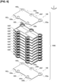
Figure 3 ] is a perspective view illustrating a state in which the cell stack assembly ofFigure 2 is disassembled to show an air shelter, an upper end plate, a stack, and a lower end plate. - [
Figure 4 ] is a perspective view illustrating a state in which the stack ofFigure 3 is disassembled to show an upper module unit, a plurality of middle module units, and a lower module unit. - [
Figure 5 ] is an exploded perspective view illustrating the upper module unit ofFigure 4 . - [
Figure 6 ] is an exploded perspective view illustrating the middle module unit ofFigure 4 . - [
Figure 7 ] is an exploded perspective view illustrating the lower module unit ofFigure 4 . - [
Figure 8 ] is an exploded perspective view illustrating the cell unit ofFigures 5 to 7 . - [
Figure 9 ] is an exploded perspective view illustrating a metal support cell assembly ofFigure 8 . - [
Figure 10 ] is a cross-sectional view of the metal support cell assembly along line 10-10 inFigure 8 . - [
Figure 11 ] is a perspective view illustrating the separator ofFigure 8 from a cathode side (side in which theseparator 102 is viewed from above as inFigure 8 ). - [
Figure 12 ] is a perspective view partially (region 12 inFigure 11 ) illustrating the separator ofFigure 11 . - [
Figure 13 ] is a perspective view illustrating the separator ofFigure 8 from an anode side (side in which theseparator 102 is viewed from below, unlike inFigure 8 ). - [
Figure 14 ] is a perspective view partially (region 14 inFigure 13 ) illustrating the separator ofFigure 13 . - [
Figure 15 ] is a cross-sectional view partially (region 15 inFigure 11 ) illustrating a state in which an auxiliary collector layer, the separator, and the metal support cell assembly ofFigure 8 are stacked. - [
Figure 16A ] is a perspective view schematically illustrating the flow of anode gas and cathode gas in the fuel cell stack. - [
Figure 16B ] is a perspective view schematically illustrating the flow of the cathode gas in the fuel cell stack. - [
Figure 16C ] is a perspective view schematically illustrating the flow of the anode gas in the fuel cell stack. - [
Figure 17A ] is a plan view illustrating the cell unit according to an embodiment, with the auxiliary collector layer omitted. - [
Figure 17B ] is a plan view illustrating the cell unit according to the embodiment, with a grid spring and the auxiliary collector layer omitted. - [
Figure 18A ] is a perspective view of the grid spring according to the embodiment. - [
Figure 18B ] is a perspective view of the grid spring according to the embodiment. - [
Figure 18C ] is a perspective view partially (region 18C inFigure 17A ) illustrating the separator ofFigure 17A . - [
Figure 19A ] is an enlarged view of the region surrounded by thebroken line 19A inFigure 15 . - [
Figure 19B ] is a perspective view illustrating raised pieces of the grid spring according to the embodiment. - [
Figure 20A ] is an enlarged perspective view of the region surrounded by thebroken line 20A inFigure 17B . - [
Figure 20B ] is an enlarged perspective view of the region surrounded by thebroken line 20A inFigure 17B , illustrating a state in which an abutting portion abuts a concave portion. - [
Figure 21 ] is a cross-sectional view of the fuel cell according to the first embodiment, corresponding toFigure 15 . - [
Figure 22A ] is a plan view illustrating the cell unit according to a second embodiment, with the auxiliary collector layer omitted. - [
Figure 22B ] is an enlarged view of the region surrounded by thebroken line 22B inFigure 22A . - [
Figure 23A ] is a plan view illustrating the cell unit according to a third embodiment, with the auxiliary collector layer omitted. - [
Figure 23B ] is a plan view illustrating the cell unit according to the third embodiment, with the grid spring and the auxiliary collector layer omitted. - Embodiments of the present invention will be explained below with reference to the appended drawings. In the drawings, the same members have been assigned the same reference symbols and redundant explanations have been omitted. In the drawings, the sizes and proportions of the members have been exaggerated for ease of understanding the embodiment and may differ from actual sizes and proportions.
- The orientations of members constituting a fuel cell stack are shown using arrows indicated by X, Y, and Z in each of the drawings. The direction of the arrow indicated by X is the transverse direction X of the fuel cell stack. The direction of the arrow indicated by Y is the longitudinal direction Y of the fuel cell stack. The direction of the arrow indicated by Z is the stacking direction Z of the fuel cell stack.
- As shown in
Figures 1 and2 , thefuel cell 100 is formed by sandwiching acell stack assembly 100M from above and below with acover 112 that protects thecell stack assembly 100M and anexternal manifold 111 that supplies gas from the outside. - As shown in
Figures 2 and3 , thecell stack assembly 100M is formed by sandwiching afuel cell stack 100S from above and below with anupper end plate 109 and alower end plate 108, which are then covered with anair shelter 110 that seals cathode gas CG. - As shown in
Figures 3 and4 , thefuel cell stack 100S is formed by stacking anupper module unit 100P, a plurality of middle module units 100Q, and alower module unit 100R. - As shown in
Figure 5 , theupper module unit 100P is formed by sandwiching a plurality ofstacked cell units 100T (corresponding to a fuel cell unit) from above and below with anupper collector plate 106 that outputs electric power generated by thecell units 100T to the outside, and amodule end 105, which corresponds to an end plate. - As shown in
Figure 6 , the middle module unit 100Q is formed by sandwiching a plurality of thestacked cell units 100T from above and below with a pair of the module ends 105. - As shown in
Figure 7 , thelower module unit 100R is formed by sandwiching a plurality of thestacked cell units 100T from above and below with the module ends 105 and alower collector plate 107. - As shown in
Figure 8 , thecell unit 100T includes a metalsupport cell assembly 101 provided withmetal support cells 101N havingpower generation cells 101M that generate power by using supplied gas, aseparator 102 that separates adjacentpower generation cells 101M (not shown inFigure 8 ), sealingmembers 104 that partially seal the gap between the metalsupport cell assembly 101 and theseparator 102 and restricts the flow of the gas, and grid springs 120 that are in conductive contact with one of thepower generation cells 101M and that generates an elastic force that presses theseparator 102 toward anotherpower generation cell 101M that is adjacent to the onepower generation cell 101M. - As shown in
Figure 8 , the metalsupport cell assembly 101 and theseparator 102 constitute a joined body 100U by annular joining at the outer edges thereof along a joining line V. Thecell unit 100T is formed by disposing the sealingmembers 104 between the joined body 100U and the joined body 100U that are vertically adjacent to each other. - The
fuel cell stack 100S will be described below for each configuration. - As shown in
Figures 9 and10 , the metalsupport cell assembly 101 is provided withpower generation cells 101M that generate power by using supplied gas. - In the metal
support cell assembly 101, thepower generation cell 101M is formed by sandwiching anelectrolyte 101S between a fuel electrode-side electrode (anode 101T) and an oxidant electrode-side electrode (cathode 101U), as shown inFigures 9 and10 . Themetal support cell 101N is configured from thepower generation cell 101M and asupport metal 101V that supports thepower generation cell 101M from one side. The metalsupport cell assembly 101 is configured from a pair ofmetal support cells 101N and acell frame 101W that holds the pair ofmetal support cells 101N from the periphery. In the metalsupport cell assembly 101, thepower generation cell 101M is formed by sandwiching theelectrolyte 101S with theanode 101T and thecathode 101U, as shown inFigures 9 and10 . - As shown in
Figures 9 and10 , theelectrolyte 101S allows oxide ions to pass from thecathode 101U to theanode 101T. Theelectrolyte 101S allows oxide ions to pass but does not allow gas and electrons to pass. Theelectrolyte 101S is formed into a rectangular parallelepiped shape. Theelectrolyte 101S is made of a solid oxide ceramic, such as stabilized zirconia in which yttria, neodymium oxide, samaria, gadria, scandia, and the like are dissolved. - As shown in
Figures 9 and10 , theanode 101T is a fuel electrode and reacts an anode gas AG (for example, hydrogen) with oxide ions to thereby generate an oxide of the anode gas AG and extract electrons. Theanode 101T is resistant to a reducing atmosphere, allows the anode gas AG to pass therethrough, has high electrical conductivity, and has a catalytic action to react the anode gas AG with the oxide ions. Theanode 101T is formed into a rectangular parallelepiped shape that is larger than theelectrolyte 101S. Theanode 101T is made of cemented carbide, in which, for example, a metal such as nickel and an oxide ion conductor such as yttria-stabilized zirconia are mixed. - As shown in
Figures 9 and10 , thecathode 101U is an oxidant electrode, and reacts a cathode gas CG (for example, oxygen contained in air) with electrons to convert oxygen molecules into oxide ions. Thecathode 101U is resistant to an oxidizing atmosphere, allows the cathode gas CG to pass therethrough, has high electrical conductivity, and has a catalytic action to convert oxygen molecules into oxide ions. Thecathode 101U is formed into a rectangular parallelepiped shape that is smaller than theelectrolyte 101S. Thecathode 101U is made of an oxide of, for example, lanthanum, strontium, manganese, or cobalt. - As shown in
Figures 9 and10 , thesupport metal 101V supports thepower generation cells 101M on theanode 101T side. Thesupport metal 101V has gas permeability, high electrical conductivity, and sufficient strength. Thesupport metal 101V is formed into a rectangular parallelepiped shape that is sufficiently larger than theanode 101T. Thesupport metal 101V is made of, for example, stainless steel, corrosion-resistant steel, or a corrosion-resistant alloy containing nickel and chromium. - As shown in
Figures 9 and10 , thecell frame 101W holds themetal support cell 101N from the periphery. Thecell frame 101W is formed into a thin rectangular shape. Thecell frame 101W is provided with a pair ofopenings 101k along the longitudinal direction Y. Each of the pair ofopenings 101k of thecell frame 101W is formed of a rectangular through-hole, and is smaller than the outer shape of thesupport metal 101V. Thecell frame 101W is made of metal, and is insulated with an insulating material or a coating. The insulating material is formed, for example, by fixing aluminum oxide onto thecell frame 101W. The outer edge of thesupport metal 101V is joined to the inner edge of theopening 101k of thecell frame 101W to thereby join the metalsupport cell assembly 101 to thecell frame 101W. - As shown in
Figures 9 and10 , thecell frame 101W is provided with circular extended portions (firstextended portion 101p, secondextended portion 101q, and thirdextended portion 101r) extending in the planar direction from the right end, the center, and the left end of one side along the longitudinal direction Y. Thecell frame 101W is provided with circular extended portions (fourthextended portion 101s and fifthextended portion 101t) extending in the planar direction from two locations separated from the center of the other side along the longitudinal direction Y. In thecell frame 101W, the fourthextended portion 101s and the fifthextended portion 101t are located alternatingly with respect to the firstextended portion 101p, the secondextended portion 101q, and the thirdextended portion 101r, and separated therefrom by the pair ofopenings 101k, in the longitudinal direction Y. - As shown in
Figures 9 and10 , in thecell frame 101W, an anode-sidefirst inlet 101a, an anode-sidesecond inlet 101b, and an anode-sidethird inlet 101c through which the anode gas AG passes (flows) are provided in the firstextended portion 101p, the secondextended portion 101q, and the thirdextended portion 101r, respectively. In thecell frame 101W, an anode-sidefirst outlet 101d and an anode-sidesecond outlet 101e through which the anode gas AG passes (flows) are provided in the fourthextended portion 101s and the fifthextended portion 101t, respectively. The anode-sidefirst inlet 101a, the anode-sidesecond inlet 101b, the anode-sidethird inlet 101c, the anode-sidefirst outlet 101d, and the anode-sidesecond outlet 101e of the anode gas AG are so-called manifolds. - As shown in
Figure 9 , in thecell frame 101W, a cathode-sidefirst inlet 101f through which the cathode gas CG passes (flows) is provided in the space between the firstextended portion 101p and the secondextended portion 101q. In thecell frame 101W, a cathode-sidesecond inlet 101g through which the cathode gas CG passes (flows) is provided in the space between the secondextended portion 101q and the thirdextended portion 101r. In thecell frame 101W, a cathode-sidefirst outlet 101h through which the cathode gas CG passes (flows) is provided on the right side of the fourthextended portion 101s inFigure 9 . In thecell frame 101W, a cathode-sidesecond outlet 101i through which the cathode gas CG passes (flows) is provided in the space between the fourthextended portion 101s and the fifthextended portion 101t. In thecell frame 101W, a cathode-sidethird outlet 101j through which the cathode gas CG passes (flows) is provided on the left side of the fifthextended portion 101t inFigure 9 . In thecell frame 101W, the cathode-sidefirst inlet 101f, the cathode-sidesecond inlet 101g, the cathode-sidefirst outlet 101h, the cathode-sidesecond outlet 101i, and the cathode-sidethird outlet 101j correspond to the space between the outer circumferential surface of thecell frame 101W and the inner-side surface of theair shelter 110. - As shown in
Figure 15 , theseparator 102 definesflow path portions 102L, which are flow passages for the anode gas AG and the cathode gas CG between the separator and thepower generation cells 101M. Theseparator 102 is in conductive contact with themetal support cell 101N. - The
separator 102 is disposed opposing the metalsupport cell assembly 101. Theseparator 102 has the same outer shape as the metalsupport cell assembly 101. Theseparator 102 is made of metal, and is insulated using an insulating material or a coating, excluding regions (flowpath portions 102L) opposing thepower generation cells 101M. The insulating material is formed, for example, by fixing aluminum oxide onto theseparator 102. Theseparator 102 is provided with a pair of theflow path portions 102L arranged side by side in the longitudinal direction Y so as to oppose thepower generation cells 101M. - As shown in
Figures 8 as well asFigures 11-15 , in theseparator 102, theflow path portions 102L are formed by arranging flow paths that extend along the direction of the flow of the gas (transverse direction X) in the direction (longitudinal direction Y) orthogonal to the direction of the flow of the gas (transverse direction X). As shown inFigures 12 ,14 , and15 ,concave portions 102y are provided in theflow path portions 102L at regular intervals, so as to be recessed downward fromflat portions 102x, in a plane defined by the longitudinal direction Y and the transverse direction X. Theconcave portions 102y extend along the direction of the flow of the gas (transverse direction X). Theconcave portions 102y are recessed downward from the lower end of theseparator 102. As shown inFigures 12 ,14 , and15 ,convex portions 102z are provided in theflow path portions 102L at regular intervals, so as to protrude upward from theflat portions 102x. Theconvex portions 102z extend along the direction of the flow of the gas (transverse direction X). Theconvex portions 102z protrude upward from the upper end of theseparator 102. In theflow path portions 102L, theconcave portions 102y and theconvex portions 102z are alternatingly provided along the longitudinal direction Y, separated by theflat portions 102x. - As shown in
Figure 15 , in theseparator 102, the gap between theflow path portion 102L and the metalsupport cell assembly 101 located below (on the right inFigure 15 ) is configured to be the flow path of the anode gas AG. The anode gas AG flows from an anode-sidesecond inlet 102b of theseparator 102, shown inFigure 13 , and the like, through a plurality ofgrooves 102q, shown inFigures 13 and14 , into theflow path portion 102L on the anode side. As shown inFigures 13 and14 , in theseparator 102, the plurality ofgrooves 102q are formed from each of an anode-sidefirst inlet 102a, the anode-sidesecond inlet 102b, and an anode-sidethird inlet 102c, radially toward theflow path portion 102L on the anode side. As shown inFigures 12 and15 , in theseparator 102, the gap between theflow path portion 102L and the metalsupport cell assembly 101 located above (on the left inFigure 15 ) is configured to be the flow path of the cathode gas CG. The cathode gas CG flows from a cathode-sidefirst inlet 102f and a cathode-sidesecond inlet 102g of theseparator 102 shown inFigure 11 , over anouter edge 102p on the cathode side of theseparator 102 shown inFigures 11 and12 , into theflow path portion 102L on the cathode side. As shown inFigure 12 , in theseparator 102, theouter edge 102p on the cathode side is formed to be thinner than the other portions. - As shown in
Figures 8 ,11 , and13 , theseparator 102 is provided with the anode-sidefirst inlet 102a, the anode-sidesecond inlet 102b, the anode-sidethird inlet 102c, an anode-sidefirst outlet 102d, and an anode-sidesecond outlet 102e through which the anode gas AG passes, such that the relative position with the metalsupport cell assembly 101 matches along the stacking direction Z. Theseparator 102 is provided with the cathode-sidefirst inlet 102f, the cathode-sidesecond inlet 102g, a cathode-sidefirst outlet 102h, a cathode-sidesecond outlet 102i, and a cathode-sidethird outlet 102j through which the cathode gas CG passes, such that the relative position with the metalsupport cell assembly 101 matches along the stacking direction Z. In theseparator 102, the cathode-sidefirst inlet 102f, the cathode-sidesecond inlet 102g, the cathode-sidefirst outlet 102h, the cathode-sidesecond outlet 102i, and the cathode-sidethird outlet 102j correspond to the space between the outer circumferential surface of theseparator 102 and the inner-side surface of theair shelter 110. - As shown in
Figures 8 and15 , thegrid spring 120 presses theseparator 102 toward thepower generation cell 101M. Thegrid spring 120 is in conductive contact with thepower generation cell 101M via anauxiliary collector layer 103. - The
auxiliary collector layer 103 forms a space through which the cathode gas CG passes between thepower generation cell 101M and thegrid spring 120, equalizes the surface pressure, and assists the electrical contact between thepower generation cell 101M and thegrid spring 120. - The
auxiliary collector layer 103 is a so-called expanded metal. Theauxiliary collector layer 103 is disposed between thepower generation cell 101M and theflow path portions 102L of theseparator 102. Theauxiliary collector layer 103 has the same outer shape as thepower generation cell 101M. Theauxiliary collector layer 103 has a wire mesh shape in which rhomboidal, etc., openings are provided in a lattice pattern. - The sealing
members 104 are so-called gaskets, which function as a spacer and a seal. - As shown in
Figure 8 , the sealingmembers 104 are disposed between thecell frame 101W and theseparator 102 and partially seals the gap between thecell frame 101W and theseparator 102 to thereby restrict the flow of the gas. - The sealing
members 104 prevent the anode gas AG from becoming mixed toward the cathode-side flow path of theseparator 102 from an anode-side inlet (for example, the anode-sidefirst inlet 102a) and an anode-side outlet (for example, anode-sidefirst outlet 102d) of theseparator 102. - As shown in
Figures 5 to 7 , themodule end 105 is a plate that holds the lower end or the upper end of the plurality ofstacked cell units 100T. - The
module end 105 is disposed at the lower end or the upper end of the plurality ofstacked cell units 100T. Themodule end 105 has the same outer shape as thecell units 100T. Themodule end 105 is made of a conductive material that does not allow gas to permeate therethrough and, except for partial regions that oppose thepower generation cells 101M and the other module ends 105, is insulated using an insulating material or a coating. The insulating material is formed, for example, by fixing aluminum oxide onto themodule end 105. - The
module end 105 is provided with an anode-sidefirst inlet 105a, an anode-sidesecond inlet 105b, an anode-sidethird inlet 105c, an anode-sidefirst outlet 105d, and an anode-sidesecond outlet 105e through which the anode gas AG passes, such that the relative position with thecell units 100T matches along the stacking direction Z. Themodule end 105 is provided with a cathode-sidefirst inlet 105f, a cathode-sidesecond inlet 105g, a cathode-sidefirst outlet 105h, a cathode-sidesecond outlet 105i, and a cathode-sidethird outlet 105j through which the cathode gas CG passes, such that the relative position with thecell units 100T matches along the stacking direction Z. In themodule end 105, the cathode-sidefirst inlet 105f, the cathode-sidesecond inlet 105g, the cathode-sidefirst outlet 105h, the cathode-sidesecond outlet 105i, and the cathode-sidethird outlet 105j correspond to the space between the outer circumferential surface of themodule end 105 and the inner-side surface of theair shelter 110. - The
upper collector plate 106 is shown inFigure 5 and outputs electric power generated by thecell units 100T to the outside. - As shown in
Figure 5 , theupper collector plate 106 is positioned at the upper end of theupper module unit 100P. Theupper collector plate 106 has the same outer shape as thecell units 100T. Theupper collector plate 106 is provided with a terminal (not shown) that is connected to an external energizing member. Theupper collector plate 106 is made of a conductive material that does not allow gas to permeate therethrough, and is insulated using an insulating material or a coating, excluding the terminal portion and regions that oppose thepower generation cells 101M of thecell units 100T. The insulating material is formed, for example, by fixing aluminum oxide onto theupper collector plate 106. - The
lower collector plate 107 is shown inFigure 7 , and outputs electric power generated by thecell units 100T to the outside. - As shown in
Figure 7 , thelower collector plate 107 is positioned at the lower end of thelower module unit 100R. Thelower collector plate 107 has the same outer shape as theupper collector plate 106. Thelower collector plate 107 is provided with a terminal (not shown) that is connected to an external energizing member. Thelower collector plate 107 is made of a conductive material that does not allow gas to permeate therethrough and, except for the terminal portion and regions that oppose thepower generation cells 101M of thecell units 100T, is insulated using an insulating material or a coating. The insulating material is formed, for example, by fixing aluminum oxide onto thelower collector plate 107. - The
lower collector plate 107 is provided with an anode-sidefirst inlet 107a, an anode-sidesecond inlet 107b, an anode-sidethird inlet 107c, an anode-sidefirst outlet 107d, and an anode-sidesecond outlet 107e through which the anode gas AG passes, such that the relative position with thecell units 100T matches along the stacking direction Z. Thelower collector plate 107 is provided with a cathode-sidefirst inlet 107f, a cathode-sidesecond inlet 107g, a cathode-sidefirst outlet 107h, a cathode-side second outlet 107i, and a cathode-sidethird outlet 107j through which the cathode gas CG passes, such that the relative position with thecell units 100T matches along the stacking direction Z. In thelower collector plate 107, the cathode-sidefirst inlet 107f, the cathode-sidesecond inlet 107g, the cathode-sidefirst outlet 107h, the cathode-side second outlet 107i, and the cathode-sidethird outlet 107j correspond to the space between the outer circumferential surface of thelower collector plate 107 and the inner-side surface of theair shelter 110. - As shown in
Figures 2 and3 , thelower end plate 108 holds thefuel cell stack 100S from below. - The
lower end plate 108 is disposed at the lower end of thefuel cell stack 100S. Except for a part, thelower end plate 108 has the same outer shape as thecell units 100T. Two ends of thelower end plate 108 are formed by linearly extending both ends along the longitudinal direction Y in order to form an inlet and an outlet for the cathode gas CG. Thelower end plate 108 is formed sufficiently thicker than thecell units 100T. Thelower end plate 108 is made of metal, for example, and the upper surface thereof that contacts thelower collector plate 107 is insulated using an insulating material or a coating. The insulating material is formed, for example, by fixing aluminum oxide onto thelower end plate 108. - The
lower end plate 108 is provided with an anode-sidefirst inlet 108a, an anode-sidesecond inlet 108b, an anode-sidethird inlet 108c, an anode-sidefirst outlet 108d, and an anode-sidesecond outlet 108e through which the anode gas AG passes, such that the relative position with thecell units 100T matches along the stacking direction Z. Thelower end plate 108 is provided with a cathode-sidefirst inlet 108f, a cathode-sidesecond inlet 108g, a cathode-sidefirst outlet 108h, a cathode-side second outlet 108i, and a cathode-side third outlet 108j through which the cathode gas CG passes, such that the relative position with thecell units 100T matches along the stacking direction Z. - As shown in
Figures 2 and3 , theupper end plate 109 holds thefuel cell stack 100S from above. - The
upper end plate 109 is disposed at the upper end of thefuel cell stack 100S. Theupper end plate 109 has the same outer shape as thelower end plate 108. Unlike thelower end plate 108, theupper end plate 109 is not provided with an inlet and an outlet for the gas. Theupper end plate 109 is made of metal, for example, and the lower surface thereof that contacts theupper collector plate 106 is insulated using an insulating material or a coating. The insulating material is formed, for example, by fixing aluminum oxide onto theupper end plate 109. - As shown in
Figures 2 and3 , theair shelter 110 forms a flow path for the cathode gas CG between the air shelter and thefuel cell stack 100S. - As shown in
Figures 2 and3 , theair shelter 110 covers thefuel cell stack 100S, which is sandwiched between thelower end plate 108 and theupper end plate 109, from the top. Theair shelter 110 forms the inlet and the outlet for the cathode gas CG, which is a constituent element of thefuel cell stack 100S, with a gap between the inner-side surface of theair shelter 110 and the side surface of thefuel cell stack 100S. Theair shelter 110 has a box-like shape, with the entire lower portion and part of the side portion open. Theair shelter 110 is made of metal, for example, and the inner-side surface thereof is insulated using an insulating material or a coating. The insulating material is formed, for example, by fixing aluminum oxide onto theair shelter 110. - As shown in
Figures 1 and2 , theexternal manifold 111 supplies gas from the outside to the plurality ofcell units 100T. - The
external manifold 111 is disposed below thecell stack assembly 100M. Theexternal manifold 111 has an outer shape obtained by simplifying the shape of thelower end plate 108. Theexternal manifold 111 is formed sufficiently thicker than thelower end plate 108. Theexternal manifold 111 is made of metal, for example. - The
external manifold 111 is provided with an anode-sidefirst inlet 111a, an anode-sidesecond inlet 111b, an anode-sidethird inlet 111c, an anode-sidefirst outlet 111d, and an anode-sidesecond outlet 111e through which the anode gas AG passes, such that the relative position with thecell units 100T matches along the stacking direction Z. Theexternal manifold 111 is provided with a cathode-sidefirst inlet 111f, a cathode-sidesecond inlet 111g, a cathode-sidefirst outlet 111h, a cathode-sidesecond outlet 111i, and a cathode-sidethird outlet 111j through which the cathode gas CG passes, such that the relative position with thecell units 100T matches along the stacking direction Z. - As shown in
Figures 1 and2 , thecover 112 covers and protects thecell stack assembly 100M. - The
cover 112 sandwiches thecell stack assembly 100M from above and below together with theexternal manifold 111. Thecover 112 has a box-like shape, with an open lower portion. Thecover 112 is made of metal, for example, the inner surface of which is insulated with an insulating material. -
Figure 16A is a perspective view schematically illustrating the flow of the anode gas AG in thefuel cell stack 100S.Figure 16B is a perspective view schematically illustrating the flow of the cathode gas CG in thefuel cell stack 100S. - The anode gas AG passes through the respective inlets of the
external manifold 111, thelower end plate 108, themodule end 105, theseparator 102, and the metalsupport cell assembly 101 and is supplied to theanode 101T of each of thepower generation cells 101M. That is, the anode gas AG is distributed and supplied to the flow path on the anode side provided in the gap between theseparator 102 and the metalsupport cell assembly 101, which are stacked in alternating fashion from theexternal manifold 111 to the terminalupper collector plate 106. Thereafter, the anode gas AG reacts in thepower generation cells 101M, passes through the respective outlets of each of the constituent elements described above, and is discharged in the form of exhaust gas. - In
Figure 16A , the anode gas AG passes through the anode-sidefirst inlet 102a, the anode-sidesecond inlet 102b, and the anode-sidethird inlet 102c of theseparator 102 positioned below inFigure 16A , passes through the anode-sidefirst inlet 101a, the anode-sidesecond inlet 101b, and the anode-sidethird inlet 101c of the metalsupport cell assembly 101, then flows into theflow path portions 102L of theseparator 102 positioned above inFigure 16A , and is supplied to theanodes 101T of thepower generation cells 101M of the metalsupport cell assembly 101. The anode gas AG that has reacted in theanode 101T flows out of theflow path portions 102L of theseparator 102 positioned above inFigure 16A in the form of exhaust gas, passes through the anode-sidefirst outlet 101d and the anode-sidesecond outlet 101e of the metalsupport cell assembly 101, passes through the anode-sidefirst outlet 102d and the anode-sidesecond outlet 102e of theseparator 102 positioned below inFigure 16A , and is discharged to the outside. - The cathode gas CG passes through the respective inlets of the
external manifold 111, thelower end plate 108, themodule end 105, theseparator 102, and the metalsupport cell assembly 101 and is supplied to thecathodes 101U of thepower generation cells 101M. That is, the cathode gas CG is distributed and supplied to the flow path on the cathode side provided in the gap between the metalsupport cell assembly 101 and theseparator 102, which are stacked in alternating fashion from theexternal manifold 111 to the terminalupper collector plate 106. The cathode gas CG then reacts in thepower generation cells 101M, passes through the respective outlets of each of the constituent elements described above, and is discharged in the form of exhaust gas. The cathode gas CG is supplied from one end 102S1 of theseparator 102 and flows along the planar direction of theseparator 102 toward the other end 102S2 opposing the one end 102S1 (refer toFigure 16B ). The inlet and the outlet of the cathode gas CG in each of the constituent elements described above are configured by the gaps between the outer circumferential surface of each constituent element and the inner-side surface of theair shelter 110. - In
Figure 16B , the cathode gas CG passes through the cathode-sidefirst inlet 102f and the cathode-sidesecond inlet 102g of theseparator 102 positioned below inFigure 16B , flows into theflow path portions 102L of theseparator 102, and is supplied to thecathodes 101U of thepower generation cells 101M of the metalsupport cell assembly 101. The cathode gas CG that has reacted in thecathode 101U flows out of theflow path portions 102L of theseparator 102 positioned below inFigure 16B in the form of exhaust gas, passes through the cathode-sidefirst outlet 102h, the cathode-sidesecond outlet 102i, and the cathode-sidethird outlet 102j of theseparator 102, and is discharged to the outside. - As shown in
Figure 17A , thegrid spring 120 includes afirst grid spring 120A disposed on the upstream side of the flow of the cathode gas CG, asecond grid spring 120B disposed on the downstream side of the flow of the cathode gas CG, and athird grid spring 120C disposed between thefirst grid spring 120A and thesecond grid spring 120B. - As shown in
Figures 18A-18C and19A , thegrid spring 120 has aflat substrate 125, and a plurality of elastically deformable raised pieces 130 (corresponding to spring members) that are raised so as to be cantilevered from thesubstrate 125. - The raised
pieces 130 function as a spring that generates surface pressure between thesubstrate 125 and thepower generation cell 101M as well as between theseparator 102 and themetal support cell 101N by generating an elastic force in the stacking direction Z (refer toFigure 15 ). - As shown in
Figure 19A , the raisedpieces 130 each have aplanar portion 131 joined to theseparator 102, aspring portion 132 extending from theplanar portion 131, apillar portion 133 extending from thespring portion 132 toward a direction away from theplanar portion 131, an abuttingportion 134 abutting avertical wall 102r of aconcave portion 102y (corresponding to a groove), and anauxiliary pillar portion 135 extending from thespring portion 132 toward theplanar portion 131. - The
planar portion 131 is joined to theseparator 102 in a state of surface contact with theseparator 102. Theplanar portion 131 and theseparator 102 are welded and joined at a joint portion M. The length of theplanar portion 131 is greater than the width required for welding and joining theplanar portion 131 and the separator 102 (width B0 of the joint portion M). - The
spring portion 132 receives force in the stacking direction Z to generate an elastic force for pressing theseparator 102 toward thepower generation cell 101M by bending and deforming. - The
spring portion 132 has acurved portion 132a curved in a direction away from theplanar portion 131, and the curvature of thecurved portion 132a is determined in accordance with the required reaction force. - The
pillar portion 133 extends along the stacking direction Z toward a direction away from theplanar portion 131. - The abutting
portion 134 extends from theplanar portion 131 toward a direction different from the direction in which thespring portion 132 extends. The abuttingportion 134 abuts thevertical wall 102r of theconcave portion 102y in a state in which theplanar portion 131 is in contact with theseparator 102. Theplanar portion 131 is joined to theseparator 102 in a state in which the abuttingportion 134 abuts thevertical wall 102r of theconcave portion 102y. - The distal end of the abutting
portion 134 is bent toward the recessed direction of theconcave portion 102y. The bending angle of the distal end of the abuttingportion 134 is not particularly limited. The distance between the distal end of the abuttingportion 134 and theplanar portion 131 in the stacking direction Z is less than the depth of theconcave portion 102y. - The
auxiliary pillar portion 135 extends from thespring portion 132 in a direction toward theplanar portion 131 along the stacking direction Z. - The width B1 of the
auxiliary pillar portion 135 increases from thespring portion 132 toward theplanar portion 131. The length of theauxiliary pillar portion 135 is adjusted such that a gap is formed with respect to theseparator 102 to which theplanar portion 131 is joined in a state in which no force acts on thegrid spring 120 in the stacking direction Z. - The
spring portion 132 has anopening 132b that is open in the stacking direction Z. The section modulus of thespring portion 132 increases with the distance from theplanar portion 131 due to theopening 132b. - The
opening 132b is disposed in the center of thespring portion 132 in the width direction. Theopening 132b has a symmetrical shape with respect to a center line of thespring portion 132 in the width direction. In thespring portion 132, theopening 132b extends from the side connected to theplanar portion 131 toward the side connected to thepillar portion 133. The width B2 of theopening 132b decreases in the direction from theplanar portion 131 to thepillar portion 133. - In the
spring portion 132, the width B3 of the portion excluding theopening 132b increases in the direction from theplanar portion 131 to thepillar portion 133. - The
auxiliary pillar portion 135 has a shape in which a part of thespring portion 132 is notched and bent. Theopening 132b is formed together with theauxiliary pillar portion 135 by notching and bending a part of thespring portion 132. - As shown in
Figures 20A and20B , theconcave portion 102y has a first vertical wall 102r1 that intersects the direction in which the abuttingportion 134 extends (direction indicated by reference symbol Y inFigure 20B ) and a second vertical wall 102r2 that is along the direction in which the abuttingportion 134 extends. As shown inFigure 20B , the abuttingportion 134 abuts the first vertical wall 102r1 while abutting the second vertical wall 102r2. - The spring constant of the raised
pieces 130 of thefirst grid spring 120A (refer toFigure 17A ) is smaller than the spring constant of the raisedpieces 130 of thesecond grid spring 120B and the spring constant of the raisedpieces 130 of thethird grid spring 120C. - The spring constant of the raised
pieces 130 of thefirst grid spring 120A, the spring constant of the raisedpieces 130 of thesecond grid spring 120B, and the spring constant of the raisedpieces 130 of thethird grid spring 120C can be adjusted, for example, by using methods such as varying the plate thickness of the raisedpieces 130 or changing the material of thegrid spring 120. In addition, the spring constants also can be adjusted by changing the curvature of thecurved portion 132a of thespring portion 132. - The action and effects of the above-described embodiment will be described below.
- The
fuel cell stack 100S is made by stacking the plurality ofcell units 100T, each having thepower generation cell 101M that is formed by sandwiching theelectrolyte 101S from both sides with theanode 101T and thecathode 101U and that generates power by using the supplied anode gas AG and cathode gas CG, and theseparator 102 that defines theflow path portions 102L, which are flow passages of theanode 101T and thecathode 101U between the separator and thepower generation cells 101M, and that is in conductive contact with thepower generation cell 101M. Thecell unit 100T has agrid spring 120 provided with raisedpieces 130 that generate an elastic force for pressing theseparator 102 toward thepower generation cell 101M. Each raisedpiece 130 has aplanar portion 131 that is joined to theseparator 102 in a state of surface contact with theseparator 102, and aspring portion 132 that extends from theplanar portion 131 and that generates an elastic force for pressing the separator toward the power generation cell by receiving a force in the stacking direction Z of the cell unit and undergoing bending deformation. - According to the
fuel cell stack 100S, thecell unit 100T and thegrid spring 120, the raisedpieces 130 are joined to theseparator 102 in a state of surface contact with theseparator 102 via theplanar portion 131. As a result, compared to a case in which the raisedpieces 130 contact theseparator 102 at the ends, the contact area between the raisedpieces 130 and theseparator 102 increases. Therefore, compared to a case in which the raisedpieces 130 contact theseparator 102 at the ends, it is possible prevent stress from being concentrated at the contact points between the raisedpieces 130 and theseparator 102. As a result, creep deformation of the raisedpieces 130 can be prevented, even when the temperature of the raisedpieces 130 becomes high due to the emission of heat from thepower generation cells 101M at the time of power generation. Thus, according to thefuel cell stack 100S, thecell unit 100T, and thegrid spring 120, it is possible to prevent a decrease in the power generation performance caused by creep deformation of the raisedpieces 130. - In particular, since the
fuel cell stack 100S according to the present embodiment is a solid oxide fuel cell (SOFC), which uses a solid oxide ceramic as theelectrolyte 101S, the operating temperature is extremely high, approximately 700 to 1000°C. Therefore, compared to a solid polymer membrane fuel cell, the raisedpieces 130 are relatively easily subjected to creep deformation at the time of operation. With the configuration described above, thefuel cell stack 100S can restrict the creep deformation of the raisedpieces 130 and maintain power generation performance even for long periods of operation in a high-temperature state. - In addition by using the
fuel cell stack 100S, thecell unit 100T and thegrid spring 120, since the raisedpieces 130 are joined to theseparator 102 via theplanar portion 131, unlike the case in which the ends of the raisedpieces 130 are not joined to theseparator 102, it is possible to prevent the occurrence of slippage between the raisedpieces 130 and theseparator 102. As a result, since the attitude of thesubstrate 125 is stabilized, the distance between theseparator 102 and thepower generation cell 101M with which thesubstrate 125 is in conductive contact can be maintained at the appropriate distance. Therefore, the pressure loss of the cathode gas CG that flows between thepower generation cell 101M and theseparator 102 is reduced, and the power generation performance of thefuel cell 100 is improved. This effect is remarkable when thefuel cell 100 is configured as a solid oxide fuel cell that has a high operating temperature, which easily causes creep deformation of the raisedpieces 130. - In addition, by using the
fuel cell stack 100S, thecell unit 100T and thegrid spring 120, thecurved portion 132a of thespring portion 132 is curved in the stacking direction Z. - By using the
fuel cell stack 100S, thecell unit 100T and thegrid spring 120, thespring portion 132 can be configured by using a simple configuration in which thecurved portion 132a is curved. Therefore, by using thefuel cell stack 100S, the manufacture thefuel cell 100 can be facilitated. - In addition, according to the
fuel cell stack 100S, thecell unit 100T, and thegrid spring 120, thecurved portion 132a is curved in such a way that it is possible to absorb the displacement of thesubstrate 125 in the planar direction of the separator 102 (direction indicated by the reference symbol Y inFigure 17 ). As a result, since the attitude of thesubstrate 125 is stabilized, the distance between theseparator 102 and thepower generation cell 101M with which thesubstrate 125 is in conductive contact can be reliably maintained at the appropriate distance. Therefore, the pressure loss of the cathode gas CG that flows between thepower generation cell 101M and theseparator 102 is more reliably reduced, so that the power generation performance of thefuel cell 100 is further improved. - In addition, in the
fuel cell stack 100S, thecell unit 100T, and thegrid spring 120, each of the raisedpieces 130 further has thepillar portion 133 that extends from thespring portion 132 along a direction intersecting theplanar portion 131 toward a direction away from theplanar portion 131. - By using the
fuel cell stack 100S, thecell unit 100T and thegrid spring 120, thepillar portions 133 can efficiently support the stacking direction Z force that acts on the raisedpieces 130 from thepower generation cells 101M. It is thereby possible to more reliably restrict the displacement of thepower generation cell 101M in the stacking direction Z. Therefore, the distance between theseparator 102 and thepower generation cell 101M with which thesubstrate 125 is in conductive contact can be more reliably maintained at the appropriate distance. Therefore, the pressure loss of the cathode gas CG that flows between thepower generation cell 101M and theseparator 102 is more reliably reduced, so that the power generation performance of thefuel cell 100 is further improved. - In addition, according to the
fuel cell stack 100S, thecell unit 100T, and thegrid spring 120, thepillar portions 133 extend in the stacking direction Z. - By using the
fuel cell stack 100S, thecell unit 100T and thegrid spring 120, thepillar portions 133 can more efficiently support the force from thepower generation cells 101M in the stacking direction Z that acts on the raisedpieces 130. It is thereby possible to more reliably restrict the displacement of thepower generation cell 101M in the stacking direction Z. - In addition, in the
fuel cell stack 100S, thecell unit 100T, and thegrid spring 120, each of the raisedpieces 130 further has theauxiliary pillar portion 135 that extends from thespring portion 132 along the stacking direction Z toward theplanar portion 131. - By using the
fuel cell stack 100S, thecell unit 100T and thegrid spring 120, when the stacking direction Z force acts on the raisedpieces 130, part of the stacking direction Z force can be received by theauxiliary pillar portions 135. It is thereby possible to prevent the raisedpieces 130 from excessively deforming in the stacking direction Z, even if the raisedpieces 130 undergo creep deformation. Therefore, by using thefuel cell stack 100S, it is possible to more reliably prevent a decrease in the power generation performance caused by creep deformation of the raisedpieces 130. - In addition, by using the
fuel cell stack 100S, thecell unit 100T, and thegrid spring 120, theauxiliary pillar portion 135 has a shape in which a part of thespring portion 132 is notched and bent. - By using the
fuel cell stack 100S, thecell unit 100T and thegrid spring 120, theauxiliary pillar portion 135 can be formed by notching a part of thespring portion 132. Therefore, according to thefuel cell stack 100S, manufacture of thefuel cell 100 can be facilitated. - In addition, according to the
fuel cell stack 100S, thecell unit 100T, and thegrid spring 120, thespring portion 132 has theopening 132b that opens in the direction of intersection. The section modulus of thespring portion 132 increases with the distance from theplanar portion 131 due to theopening 132b. - By using the
fuel cell stack 100S, thecell unit 100T and thegrid spring 120, the bending rigidity of thespring portion 132 increases with the distance from theplanar portion 131. The bending stress, which is caused by the bending deformation that starts at the portion connected to theplanar portion 131, acts more evenly in thespring portion 132. Therefore, since the stress that acts on thespring portion 132 is dispersed, it is possible to more reliably prevent creep deformation of thespring portion 132. As a result, by using thefuel cell stack 100S, it is possible to more reliably prevent a decrease in the power generation performance caused by creep deformation of the raisedpieces 130. - In addition, by using the
fuel cell stack 100S, thecell unit 100T and thegrid spring 120, theseparator 102 hasconcave portions 102y that are recessed from the surface to which the raisedpieces 130 are joined. The raisedpiece 130 further has the abuttingportion 134 that extends from theplanar portion 131 in a direction different from the direction in which thespring portion 132 extends, and that abuts thevertical wall 102r of theconcave portion 102y in a state in which theplanar portion 131 is joined to theseparator 102. - By using the
fuel cell stack 100S, thecell unit 100T and thegrid spring 120, the abuttingportion 134 abuts thevertical wall 102r of theconcave portion 102y, so that the raisedpieces 130 can be easily positioned in the planar direction of theseparator 102. Therefore, according to thefuel cell stack 100S, thecell unit 100T, and thegrid spring 120, manufacture of thefuel cell 100 can be facilitated. - In addition, in the
fuel cell stack 100S, thecell unit 100T, and thegrid spring 120, the distal end of the abuttingportion 134 is bent toward the direction of the recess of theconcave portion 102y. - By using the
fuel cell stack 100S, thecell unit 100T and thegrid spring 120, the abuttingportion 134 can more reliably abut thevertical wall 102r of theconcave portion 102y. It is thereby possible to more reliably position the raisedpieces 130 in the planar direction of theseparator 102. Therefore, according to thefuel cell stack 100S, manufacture of thefuel cell 100 can be facilitated. In addition, theconvex portion 102z improves the rigidity of theseparator 102 and increases the cross-sectional area of the anode-side flow path. - In addition, in the
fuel cell stack 100S, thecell unit 100T, and thegrid spring 120, the distance between theplanar portion 131 and the distal end of the abuttingportion 134 in the intersecting direction is less than the depth of theconcave portion 102y. - By using the
fuel cell stack 100S, thecell unit 100T and thegrid spring 120, the abuttingportion 134 can more reliably abut thevertical wall 102r of theconcave portion 102y. It is thereby possible to more reliably position the raisedpieces 130 in the planar direction of theseparator 102. Therefore, by using thefuel cell stack 100S, the manufacture of thefuel cell 100 can be facilitated. - In addition, in the
fuel cell stack 100S, thecell unit 100T, and thegrid spring 120, the cathode gas CG is supplied from one end side of theseparator 102 configuring the outer perimeter and flows along the planar direction of theseparator 102 toward the other end side opposing the one end, between thepower generation cell 101M and theseparator 102. Theconcave portion 102y has the first vertical wall 102r1 along the direction of the flow of the cathode gas CG and the second vertical wall 102r2 that intersects the direction of the flow of the gas. The abuttingportion 134 abuts the first vertical wall 102r1 while abutting the second vertical wall 102r2. - By using the
fuel cell stack 100S, thecell unit 100T and thegrid spring 120, the abuttingportion 134 abuts the first vertical wall 102r1 and the abuttingportion 134 abuts the second vertical wall 102r2, so that it is thereby possible to restrict the positions of the raisedpieces 130 in the direction of the flow of the cathode gas CG and the direction intersecting the flow direction. It is thereby possible to reliably position the raisedpieces 130 in the direction of the flow of the cathode gas CG and the direction intersecting the flow direction. Therefore, according to thefuel cell stack 100S, the manufacture of thefuel cell 100 can be facilitated. - In addition, in the
fuel cell stack 100S, thecell unit 100T, and thegrid spring 120, the length of theplanar portion 131 is greater than the width required for welding and joining theplanar portion 131 and theseparator 102. - By using the
fuel cell stack 100S, thecell unit 100T and thegrid spring 120, welding and joining theplanar portion 131 and theseparator 102 can be facilitated. It is thereby possible to more reliably ensure the conductivity between theplanar portion 131 and theseparator 102. - In addition, the
fuel cell stack 100S, thecell unit 100T, and thegrid spring 120 have a plurality of the raisedpieces 130. The plurality of the raisedpieces 130 are arranged along the planar direction of theseparator 102. - By using the
fuel cell stack 100S, thecell unit 100T and thegrid spring 120, it is possible to uniformly press theseparator 102 toward thepower generation cell 101M in the planar direction by using the plurality of raisedpieces 130. Therefore, a more uniform surface pressure can be more reliably applied between thepower generation cell 101M and theseparator 102. Therefore, the power generation performance of thefuel cell 100 is further improved. - In addition, the
fuel cell stack 100S, thecell unit 100T, and thegrid spring 120 have a plurality of the raisedpieces 130 in which theflat portions 131 are joined to theseparator 102. The cathode gas CG is supplied from one end side of theseparator 102 configuring the outer perimeter and flows along the planar direction of theseparator 102 toward the other end side opposing the one end between thepower generation cell 101M and theseparator 102. The spring constant of one raisedpiece 130 of the plurality of raisedpieces 130 is smaller than the spring constant of another raisedpieces 130 disposed on the downstream side of the direction of the flow of the cathode gas CG. - Since the temperature of the raised
pieces 130 decreases from the upstream side to the downstream side of the cathode gas CG, the thermal expansion of the raisedpieces 130 is greater on the upstream side. Therefore, the thermal stress acting on the raisedpieces 130 on the upstream side is greater than that acting on the raisedpieces 130 on the downstream side. By using the configuration described above, it is possible to better equalize the stress that acts on the raisedpieces 130, even if the thermal stress acting on the raisedpieces 130 on the upstream side is greater than that acting on the raisedpieces 130 on the downstream side. Therefore, it is possible to more reliably prevent creep deformation of the raisedpieces 130. - In the embodiment described above, the raised
pieces 130 are oriented in the same direction in the planar direction of theseparator 102. However, as shown inFigure 21 , thegrid spring 120 may have first raisedpieces 130A and second raisedpieces 130B, which are oriented in a different direction from the first raisedpieces 130A, to thereby obtain a more uniform pressing force. - Naturally, the fuel cell stack, the cell unit, and the grid spring according to the present modified example exert the same effects as the embodiment described above.
- In the embodiment and the modified example described above, the
grid spring 120 is divided into the first grid spring 121, the second grid spring 122, and the third grid spring 123. However, as shown inFigure 22A , instead of being divided, thegrid spring 120 may be in the form of a single spring. - The fuel cell stack, the cell unit, and the grid spring according to the present modified example not only exert the same effects as the embodiment described above, but also can facilitate installation when the grid spring is loaded to improve ease of assembly.
- Even if the
grid spring 120 is not divided, the spring constant of the raisedpieces 130 is adjusted such that the spring constant of one raisedpiece 130 of the plurality of raisedpieces 130 is smaller than the spring constant of another raisedpiece 130 disposed on the downstream side in the direction of the flow of the cathode gas CG. - Specifically, the spring constant of the
grid spring 120 can be adjusted by adjusting the shapes of the plurality of raisedpieces 130. For example, as shown inFigure 22B , the spring constant of the raisedpieces 130 can be adjusted by making the width B41 of one raisedpiece 130 of the plurality of raisedpieces 130 smaller than the width B42 of another raisedpiece 130 disposed on the downstream side of the direction of the flow of the cathode gas CG. The spring constant of the raisedpieces 130 can be adjusted not only by adjusting the width of the raisedpieces 130, but also by adjusting the degree of curvature of thecurved portion 132a (refer toFigure 19A ), the size of theopening 132b, or the like. - According to the present embodiment, it is thereby possible to arbitrarily and finely adjust the spring constant for each location.
- The shape of the
cell unit 100T is not limited to the shapes described in the embodiment and modified examples described above. For example, the shape of thecell unit 100T may be formed as shown inFigures 23A and 23B . - In the examples shown in
Figures 23A and 23B , the form of the contour of thecell unit 100T is essentially rectangular. The cathode-side inlet 102f and the cathode-side outlet 102h are disposed on a diagonal line of thecell unit 100T. The cathode gas CG flows from the cathode-side inlet 102f toward the cathode-side outlet 102h. - The fuel cell stack, the cell unit, and the grid spring according to the present modified example not only also exert the same effects as the embodiments described above, but also can make the flow more uniform.
- It is also possible to remove the
auxiliary collector layer 103 of the flat portion of thesubstrate 125 of thegrid spring 120 to further reduce the weight. - Besides the foregoing, various modifications to the present invention based on the configurations described in the Claims are possible, which also belong to the scope of the present invention.
- The present application is based on
Japanese Patent Application No. 2017-182979 filed on September 22, 2017 -
- 100
- Fuel cell stack,
- 100M
- Cell stack assembly,
- 100S
- Stack,
- 100T
- Cell unit (fuel cell unit),
- 100U
- Joined body,
- 100P
- Upper module unit,
- 100Q
- Middle module unit,
- 100R
- Lower module unit,
- 101
- Metal support cell assembly,
- 101M
- Power generation cell
- 101N
- Metal support cell,
- 101S
- Electrolyte,
- 101T
- Anode (electrode),
- 101U
- Cathode (electrode),
- 101V
- Support metal,
- 101W
- Cell frame,
- 101k
- Opening,
- 102
- Separator,
- 102L
- Flow path portion
- 102S1, 102S2
- End of separator
- 102p
- Outer edge,
- 102q
- Groove,
- 102r1
- First vertical wall
- 102r2
- Second vertical wall,
- 102x
- Flat portion,
- 102y
- Anode-side protrusion (groove),
- 102z
- Convex portion,
- 103
- Auxiliary collector layer,
- 104
- Sealing member,
- 105
- Module end,
- 106
- Upper collector plate,
- 107
- Lower collector plate
- 108
- Lower end plate,
- 109
- Upper end plate,
- 110
- Air shelter,
- 111
- External manifold,
- 101a, 102a, 105a, 107a, 108a, 111a
- Anode-side first inlets,
- 101b, 102b, 105b, 107b, 111b, 108b
- Anode-side second inlets,
- 101c, 102c, 105c, 107c, 111c, 108c
- Anode-side third inlets,
- 101d, 102d, 108d, 107d, 111d, 105d
- Anode-side first outlets,
- 101e, 102e, 105e, 107e, 111e, 108e
- Anode-side second outlets,
- 101f, 108f, 102f, 105f, 107f, 111f
- Cathode-side first inlets,
- 101g, 102g, 105g, 107g, 108g, 111g
- Cathode-side second inlets,
- 101h, 102h, 111h, 105h, 107h, 108h
- Cathode-side first outlets,
- 101i, 102i, 105i, 107i, 108i, 111i
- Cathode-side second outlets,
- 101j, 102j, 105j, 107j, 108j, 111j
- Cathode-side third outlets,
- 112
- Cover,
- 120
- Grid spring,
- 130
- Raised piece (spring member),
- 131
- Planar portion,
- 132
- Spring portion,
- 132a
- Curved portion
- 132b
- Opening
- 133
- Pillar portion,
- 134
- Abutting portion,
- 135
- Auxiliary pillar portion,
- V
- Joining line,
- AG
- Anode gas,
- CG
- Cathode gas,
- X
- Transverse direction (of the fuel cell stack),
- Y
- Longitudinal direction (of the fuel cell stack),
- Z
- Stacking direction (of the fuel cell stack).
Claims (9)
- A spring member (130) used for a fuel cell stack in which are stacked a plurality of fuel cell units, each of the fuel cell units having a power generation cell formed by sandwiching an electrolyte from both sides with a pair of electrodes and that generates power by using supplied gas, and a separator (102) that defines a flow path portion, which is a flow passage for the gas between the separator (102) and the power generation cell, and that is in conductive contact with the power generation cell, comprising:a planar portion (131) joined to the separator (102) in a state of surface contact with the separator (102); anda spring portion (132) extending from the planar portion (131) to generate an elastic force that presses the separator (102) toward the power generation cell by receiving a force in a stacking direction of the cell and undergoing bending deformation,characterized in thatthe spring member (130) further comprisesa pillar portion (133) extending from the spring portion (132) in a direction away from the planar portion (131) along a direction intersecting the planar portion (131),the pillar portion extends along the stacking direction (Z),an auxiliary pillar portion (135) extending from the spring portion (132) in a direction toward the planar portion (131) along the stacking direction, andthe spring portion (132) has a curved portion curved in the stacking direction.
- The spring member (130) according to claim 1, wherein the auxiliary pillar portion (135) has a shape in which a part of the spring portion (132) is notched and bent.
- The spring member (130) according to claim 1 or 2, whereinthe spring portion (132) has an opening that opens in the stacking direction, anda section modulus of the spring portion (132) increases due to the opening as a distance from the planar portion (131) increases.
- The spring member (130) according to any one of claims 1, 2 and 3, wherein a length of the planar portion (131) is greater than a width required required to weld and join the planar portion (131) and the separator (102).
- A fuel cell unit (100T) comprising:a power generation cell (101M) formed by sandwiching an electrolyte from both sides with a pair of electrodes and that generates power by using supplied gas;a separator (102) that defines a flow path portion, which is a flow passage for the gas between the separator (102) and the power generation cell, and that is in conductive contact with the power generation cell; anda spring member (130) including:a planar portion (131) joined to the separator (102),a spring portion (132) extending from the planar portion (131),a pillar portion (133) extending from the spring portion (132) toward a direction away from the planar portion (131) along a stacking direction (Z) of the cell unit,an abutting portion (134) abutting a groove (102y), andan auxiliary pillar portion (135) extending from the spring portion (132) in a direction toward the planar portion (131) along the stacking direction (Z),the spring portion (132) having a curved portion (132a) curved in the stacking direction, andthe pillar portion (133) extending from the spring portion (132) along a direction intersecting the planar portion (131) toward a direction away from the planar portion (131);whereinthe planar portion (131) is joined to the separator (102) in a state of surface contact with the separator (102),the spring portion (132) extends from the planar portion (131) to generate an elastic force that presses the separator (102) toward the power generation cell by receiving a force in the stacking direction (Z) of the cell unit and undergoing bending deformation,the separator (102) has the groove (102y) recessed from a surface to which the spring member (130) is joined,the spring member (130) further has the abutting portion (134) that extends from the planar portion (131) in a direction different from a direction in which the spring portion (132) extends, and that abuts a vertical wall of the groove (102y) in a state in which the planar portion (131) is in contact with the separator (102),a distal end of the abutting portion (134) is bent toward a recessed direction of the groove (102y), anda distance between the planar portion (131) and the distal end of the abutting portion in the stacking direction is less than a depth of the groove (102y).
- The fuel cell unit according to claim 5, whereinthe groove (102y) has a first vertical wall intersecting the direction in which the abutting portion extends, and a second vertical wall along the direction in which the abutting portion extends, andthe abutting portion (134) abuts the first vertical wall while abutting the second vertical wall.
- The fuel cell unit according to claim 5 or 6, comprising a plurality of the spring members (130) arranged along a planar direction of the separator (102).
- A fuel cell stack in which are stacked a plurality of the fuel cell units (100T) according to any one of claims 5 to 7.
- The fuel cell stack according to claim 8, further comprisinga plurality of the spring members (130) arranged along a planar direction of the separator (102), whereinthe gas is supplied from one end of an outer perimeter of the separator (102) and flows between the power generation cell and the separator (102) in the planar direction of the separator (102) toward opposite end side from the one end, anda spring constant of one of the spring members (130) from among the plurality of the spring members (130) is smaller than a spring constant of another one of the plurality of the spring members (130) that is disposed on a downstream side in a direction of gas flow.
Applications Claiming Priority (2)
| Application Number | Priority Date | Filing Date | Title |
|---|---|---|---|
| JP2017182979 | 2017-09-22 | ||
| PCT/JP2018/031818 WO2019058901A1 (en) | 2017-09-22 | 2018-08-28 | Spring member, fuel cell unit, and fuel cell stack |
Publications (4)
| Publication Number | Publication Date |
|---|---|
| EP3699990A1 EP3699990A1 (en) | 2020-08-26 |
| EP3699990A8 EP3699990A8 (en) | 2020-10-07 |
| EP3699990A4 EP3699990A4 (en) | 2021-02-17 |
| EP3699990B1 true EP3699990B1 (en) | 2022-02-23 |
Family
ID=65811267
Family Applications (1)
| Application Number | Title | Priority Date | Filing Date |
|---|---|---|---|
| EP18858248.0A Active EP3699990B1 (en) | 2017-09-22 | 2018-08-28 | Spring member, fuel cell unit, and fuel cell stack |
Country Status (5)
| Country | Link |
|---|---|
| US (1) | US11069915B2 (en) |
| EP (1) | EP3699990B1 (en) |
| JP (1) | JP6850895B2 (en) |
| CN (1) | CN111194498B (en) |
| WO (1) | WO2019058901A1 (en) |
Families Citing this family (1)
| Publication number | Priority date | Publication date | Assignee | Title |
|---|---|---|---|---|
| EP3719899B1 (en) * | 2017-11-29 | 2021-08-18 | Nissan Motor Co., Ltd. | Fuel cell stack |
Family Cites Families (17)
| Publication number | Priority date | Publication date | Assignee | Title |
|---|---|---|---|---|
| JPH01246766A (en) * | 1988-03-29 | 1989-10-02 | Toshiba Corp | Cooling plate for fuel cell |
| JPH05335024A (en) * | 1992-03-31 | 1993-12-17 | Toshiba Corp | Fuel cell |
| JPH06290797A (en) * | 1993-03-31 | 1994-10-18 | Toshiba Corp | Layer built fuel cell |
| US20020022382A1 (en) * | 2000-08-18 | 2002-02-21 | Franklin Jerrold E. | Compliant electrical contacts for fuel cell use |
| EP1415361A2 (en) * | 2000-08-18 | 2004-05-06 | Jerrold E. Franklin | Integrated and modular bsp/mea/manifold plates and compliant contacts for fuel cells |
| JP4899339B2 (en) | 2005-05-16 | 2012-03-21 | トヨタ自動車株式会社 | Fuel cell separator |
| JP5224649B2 (en) * | 2006-03-29 | 2013-07-03 | 日本碍子株式会社 | Conductive connecting member and solid oxide fuel cell |
| US8343688B2 (en) * | 2007-06-06 | 2013-01-01 | Panasonic Corporation | Polymer electrolyte fuel cell having a fastening structure including elastic members |
| JP5472674B2 (en) * | 2008-12-09 | 2014-04-16 | 日産自動車株式会社 | Current collector for fuel cell and solid oxide fuel cell |
| JP5811439B2 (en) | 2011-05-30 | 2015-11-11 | 日産自動車株式会社 | Fuel cell unit and fuel cell stack |
| JP5880822B2 (en) | 2011-10-31 | 2016-03-09 | 日産自動車株式会社 | Fuel cell stack |
| JP6366086B2 (en) * | 2012-03-15 | 2018-08-01 | 日産自動車株式会社 | Fuel cell stack |
| WO2014103528A1 (en) * | 2012-12-26 | 2014-07-03 | 日産自動車株式会社 | Fuel cell stack |
| KR101814263B1 (en) * | 2013-01-31 | 2018-01-02 | 니뽄 도쿠슈 도교 가부시키가이샤 | Fuel cell and fuel cell stack |
| US20160164110A1 (en) * | 2013-08-05 | 2016-06-09 | Nissan Motor Co., Ltd. | Deformation absorbing member and fuel cell |
| JP2017182979A (en) | 2016-03-29 | 2017-10-05 | 日立化成株式会社 | Lithium ion secondary battery |
| DE102016122590A1 (en) * | 2016-11-23 | 2018-05-24 | Audi Ag | Polar plate for a fuel cell and fuel cell stack |
-
2018
- 2018-08-28 US US16/642,408 patent/US11069915B2/en active Active
- 2018-08-28 CN CN201880061312.XA patent/CN111194498B/en active Active
- 2018-08-28 JP JP2019543507A patent/JP6850895B2/en active Active
- 2018-08-28 WO PCT/JP2018/031818 patent/WO2019058901A1/en unknown
- 2018-08-28 EP EP18858248.0A patent/EP3699990B1/en active Active
Also Published As
| Publication number | Publication date |
|---|---|
| JPWO2019058901A1 (en) | 2020-07-27 |
| JP6850895B2 (en) | 2021-03-31 |
| EP3699990A1 (en) | 2020-08-26 |
| WO2019058901A1 (en) | 2019-03-28 |
| CN111194498B (en) | 2023-03-24 |
| CN111194498A (en) | 2020-05-22 |
| US11069915B2 (en) | 2021-07-20 |
| EP3699990A8 (en) | 2020-10-07 |
| US20200235417A1 (en) | 2020-07-23 |
| EP3699990A4 (en) | 2021-02-17 |
Similar Documents
| Publication | Publication Date | Title |
|---|---|---|
| EP2525429B1 (en) | Fuel cell | |
| EP3667786B1 (en) | Fuel cell unit structure, and method for controlling fuel cell unit structure | |
| EP3699990B1 (en) | Spring member, fuel cell unit, and fuel cell stack | |
| JP2019036444A (en) | Fuel battery stack and insulation member used for fuel battery stack | |
| JP7035367B2 (en) | Fuel cell unit, fuel cell stack and fuel cell | |
| JP6933040B2 (en) | Fuel cell stack | |
| CN110998947B (en) | Fuel cell stack | |
| EP3686978A1 (en) | Spring member, fuel cell unit, fuel cell stack, and method for manufacturing fuel cell stack | |
| JP6933039B2 (en) | Fuel cell stack | |
| CN111052474B (en) | Stack structure of fuel cell and thermal strain absorbing method of fuel cell stack | |
| US11398638B2 (en) | Cell structure for fuel cell and fuel cell system | |
| WO2019146101A1 (en) | Cell unit |
Legal Events
| Date | Code | Title | Description |
|---|---|---|---|
| STAA | Information on the status of an ep patent application or granted ep patent |
Free format text: STATUS: THE INTERNATIONAL PUBLICATION HAS BEEN MADE |
|
| PUAI | Public reference made under article 153(3) epc to a published international application that has entered the european phase |
Free format text: ORIGINAL CODE: 0009012 |
|
| STAA | Information on the status of an ep patent application or granted ep patent |
Free format text: STATUS: REQUEST FOR EXAMINATION WAS MADE |
|
| 17P | Request for examination filed |
Effective date: 20200417 |
|
| AK | Designated contracting states |
Kind code of ref document: A1 Designated state(s): AL AT BE BG CH CY CZ DE DK EE ES FI FR GB GR HR HU IE IS IT LI LT LU LV MC MK MT NL NO PL PT RO RS SE SI SK SM TR |
|
| AX | Request for extension of the european patent |
Extension state: BA ME |
|
| RAP1 | Party data changed (applicant data changed or rights of an application transferred) |
Owner name: NISSAN MOTOR CO., LTD. |
|
| DAV | Request for validation of the european patent (deleted) | ||
| DAX | Request for extension of the european patent (deleted) | ||
| A4 | Supplementary search report drawn up and despatched |
Effective date: 20210120 |
|
| RIC1 | Information provided on ipc code assigned before grant |
Ipc: H01M 8/0247 20160101AFI20210114BHEP Ipc: H01M 8/026 20160101ALI20210114BHEP Ipc: H01M 8/12 20160101ALI20210114BHEP Ipc: H01M 8/2465 20160101ALI20210114BHEP Ipc: H01M 8/248 20160101ALN20210114BHEP |
|
| GRAP | Despatch of communication of intention to grant a patent |
Free format text: ORIGINAL CODE: EPIDOSNIGR1 |
|
| STAA | Information on the status of an ep patent application or granted ep patent |
Free format text: STATUS: GRANT OF PATENT IS INTENDED |
|
| RIC1 | Information provided on ipc code assigned before grant |
Ipc: H01M 8/248 20160101ALN20210923BHEP Ipc: H01M 8/026 20160101ALI20210923BHEP Ipc: H01M 8/12 20160101ALI20210923BHEP Ipc: H01M 8/2465 20160101ALI20210923BHEP Ipc: H01M 8/0247 20160101AFI20210923BHEP |
|
| INTG | Intention to grant announced |
Effective date: 20211011 |
|
| GRAS | Grant fee paid |
Free format text: ORIGINAL CODE: EPIDOSNIGR3 |
|
| GRAA | (expected) grant |
Free format text: ORIGINAL CODE: 0009210 |
|
| STAA | Information on the status of an ep patent application or granted ep patent |
Free format text: STATUS: THE PATENT HAS BEEN GRANTED |
|
| AK | Designated contracting states |
Kind code of ref document: B1 Designated state(s): AL AT BE BG CH CY CZ DE DK EE ES FI FR GB GR HR HU IE IS IT LI LT LU LV MC MK MT NL NO PL PT RO RS SE SI SK SM TR |
|
| REG | Reference to a national code |
Ref country code: GB Ref legal event code: FG4D |
|
| REG | Reference to a national code |
Ref country code: CH Ref legal event code: EP |
|
| REG | Reference to a national code |
Ref country code: DE Ref legal event code: R096 Ref document number: 602018031399 Country of ref document: DE |
|
| REG | Reference to a national code |
Ref country code: AT Ref legal event code: REF Ref document number: 1471136 Country of ref document: AT Kind code of ref document: T Effective date: 20220315 |
|
| REG | Reference to a national code |
Ref country code: IE Ref legal event code: FG4D |
|
| REG | Reference to a national code |
Ref country code: LT Ref legal event code: MG9D |
|
| REG | Reference to a national code |
Ref country code: NL Ref legal event code: MP Effective date: 20220223 |
|
| REG | Reference to a national code |
Ref country code: AT Ref legal event code: MK05 Ref document number: 1471136 Country of ref document: AT Kind code of ref document: T Effective date: 20220223 |
|
| PG25 | Lapsed in a contracting state [announced via postgrant information from national office to epo] |
Ref country code: SE Free format text: LAPSE BECAUSE OF FAILURE TO SUBMIT A TRANSLATION OF THE DESCRIPTION OR TO PAY THE FEE WITHIN THE PRESCRIBED TIME-LIMIT Effective date: 20220223 Ref country code: RS Free format text: LAPSE BECAUSE OF FAILURE TO SUBMIT A TRANSLATION OF THE DESCRIPTION OR TO PAY THE FEE WITHIN THE PRESCRIBED TIME-LIMIT Effective date: 20220223 Ref country code: PT Free format text: LAPSE BECAUSE OF FAILURE TO SUBMIT A TRANSLATION OF THE DESCRIPTION OR TO PAY THE FEE WITHIN THE PRESCRIBED TIME-LIMIT Effective date: 20220623 Ref country code: NO Free format text: LAPSE BECAUSE OF FAILURE TO SUBMIT A TRANSLATION OF THE DESCRIPTION OR TO PAY THE FEE WITHIN THE PRESCRIBED TIME-LIMIT Effective date: 20220523 Ref country code: NL Free format text: LAPSE BECAUSE OF FAILURE TO SUBMIT A TRANSLATION OF THE DESCRIPTION OR TO PAY THE FEE WITHIN THE PRESCRIBED TIME-LIMIT Effective date: 20220223 Ref country code: LT Free format text: LAPSE BECAUSE OF FAILURE TO SUBMIT A TRANSLATION OF THE DESCRIPTION OR TO PAY THE FEE WITHIN THE PRESCRIBED TIME-LIMIT Effective date: 20220223 Ref country code: HR Free format text: LAPSE BECAUSE OF FAILURE TO SUBMIT A TRANSLATION OF THE DESCRIPTION OR TO PAY THE FEE WITHIN THE PRESCRIBED TIME-LIMIT Effective date: 20220223 Ref country code: ES Free format text: LAPSE BECAUSE OF FAILURE TO SUBMIT A TRANSLATION OF THE DESCRIPTION OR TO PAY THE FEE WITHIN THE PRESCRIBED TIME-LIMIT Effective date: 20220223 Ref country code: BG Free format text: LAPSE BECAUSE OF FAILURE TO SUBMIT A TRANSLATION OF THE DESCRIPTION OR TO PAY THE FEE WITHIN THE PRESCRIBED TIME-LIMIT Effective date: 20220523 |
|
| PG25 | Lapsed in a contracting state [announced via postgrant information from national office to epo] |
Ref country code: PL Free format text: LAPSE BECAUSE OF FAILURE TO SUBMIT A TRANSLATION OF THE DESCRIPTION OR TO PAY THE FEE WITHIN THE PRESCRIBED TIME-LIMIT Effective date: 20220223 Ref country code: LV Free format text: LAPSE BECAUSE OF FAILURE TO SUBMIT A TRANSLATION OF THE DESCRIPTION OR TO PAY THE FEE WITHIN THE PRESCRIBED TIME-LIMIT Effective date: 20220223 Ref country code: GR Free format text: LAPSE BECAUSE OF FAILURE TO SUBMIT A TRANSLATION OF THE DESCRIPTION OR TO PAY THE FEE WITHIN THE PRESCRIBED TIME-LIMIT Effective date: 20220524 Ref country code: FI Free format text: LAPSE BECAUSE OF FAILURE TO SUBMIT A TRANSLATION OF THE DESCRIPTION OR TO PAY THE FEE WITHIN THE PRESCRIBED TIME-LIMIT Effective date: 20220223 Ref country code: AT Free format text: LAPSE BECAUSE OF FAILURE TO SUBMIT A TRANSLATION OF THE DESCRIPTION OR TO PAY THE FEE WITHIN THE PRESCRIBED TIME-LIMIT Effective date: 20220223 |
|
| PG25 | Lapsed in a contracting state [announced via postgrant information from national office to epo] |
Ref country code: IS Free format text: LAPSE BECAUSE OF FAILURE TO SUBMIT A TRANSLATION OF THE DESCRIPTION OR TO PAY THE FEE WITHIN THE PRESCRIBED TIME-LIMIT Effective date: 20220623 |
|
| PG25 | Lapsed in a contracting state [announced via postgrant information from national office to epo] |
Ref country code: SM Free format text: LAPSE BECAUSE OF FAILURE TO SUBMIT A TRANSLATION OF THE DESCRIPTION OR TO PAY THE FEE WITHIN THE PRESCRIBED TIME-LIMIT Effective date: 20220223 Ref country code: SK Free format text: LAPSE BECAUSE OF FAILURE TO SUBMIT A TRANSLATION OF THE DESCRIPTION OR TO PAY THE FEE WITHIN THE PRESCRIBED TIME-LIMIT Effective date: 20220223 Ref country code: RO Free format text: LAPSE BECAUSE OF FAILURE TO SUBMIT A TRANSLATION OF THE DESCRIPTION OR TO PAY THE FEE WITHIN THE PRESCRIBED TIME-LIMIT Effective date: 20220223 Ref country code: EE Free format text: LAPSE BECAUSE OF FAILURE TO SUBMIT A TRANSLATION OF THE DESCRIPTION OR TO PAY THE FEE WITHIN THE PRESCRIBED TIME-LIMIT Effective date: 20220223 Ref country code: DK Free format text: LAPSE BECAUSE OF FAILURE TO SUBMIT A TRANSLATION OF THE DESCRIPTION OR TO PAY THE FEE WITHIN THE PRESCRIBED TIME-LIMIT Effective date: 20220223 Ref country code: CZ Free format text: LAPSE BECAUSE OF FAILURE TO SUBMIT A TRANSLATION OF THE DESCRIPTION OR TO PAY THE FEE WITHIN THE PRESCRIBED TIME-LIMIT Effective date: 20220223 |
|
| REG | Reference to a national code |
Ref country code: DE Ref legal event code: R097 Ref document number: 602018031399 Country of ref document: DE |
|
| PG25 | Lapsed in a contracting state [announced via postgrant information from national office to epo] |
Ref country code: AL Free format text: LAPSE BECAUSE OF FAILURE TO SUBMIT A TRANSLATION OF THE DESCRIPTION OR TO PAY THE FEE WITHIN THE PRESCRIBED TIME-LIMIT Effective date: 20220223 |
|
| PLBE | No opposition filed within time limit |
Free format text: ORIGINAL CODE: 0009261 |
|
| STAA | Information on the status of an ep patent application or granted ep patent |
Free format text: STATUS: NO OPPOSITION FILED WITHIN TIME LIMIT |
|
| 26N | No opposition filed |
Effective date: 20221124 |
|
| PG25 | Lapsed in a contracting state [announced via postgrant information from national office to epo] |
Ref country code: SI Free format text: LAPSE BECAUSE OF FAILURE TO SUBMIT A TRANSLATION OF THE DESCRIPTION OR TO PAY THE FEE WITHIN THE PRESCRIBED TIME-LIMIT Effective date: 20220223 |
|
| PG25 | Lapsed in a contracting state [announced via postgrant information from national office to epo] |
Ref country code: MC Free format text: LAPSE BECAUSE OF FAILURE TO SUBMIT A TRANSLATION OF THE DESCRIPTION OR TO PAY THE FEE WITHIN THE PRESCRIBED TIME-LIMIT Effective date: 20220223 |
|
| REG | Reference to a national code |
Ref country code: CH Ref legal event code: PL |
|
| PG25 | Lapsed in a contracting state [announced via postgrant information from national office to epo] |
Ref country code: LU Free format text: LAPSE BECAUSE OF NON-PAYMENT OF DUE FEES Effective date: 20220828 Ref country code: LI Free format text: LAPSE BECAUSE OF NON-PAYMENT OF DUE FEES Effective date: 20220831 Ref country code: CH Free format text: LAPSE BECAUSE OF NON-PAYMENT OF DUE FEES Effective date: 20220831 |
|
| REG | Reference to a national code |
Ref country code: BE Ref legal event code: MM Effective date: 20220831 |
|
| PG25 | Lapsed in a contracting state [announced via postgrant information from national office to epo] |
Ref country code: IT Free format text: LAPSE BECAUSE OF FAILURE TO SUBMIT A TRANSLATION OF THE DESCRIPTION OR TO PAY THE FEE WITHIN THE PRESCRIBED TIME-LIMIT Effective date: 20220223 Ref country code: IE Free format text: LAPSE BECAUSE OF NON-PAYMENT OF DUE FEES Effective date: 20220828 |
|
| REG | Reference to a national code |
Ref country code: DE Ref legal event code: R084 Ref document number: 602018031399 Country of ref document: DE |
|
| PG25 | Lapsed in a contracting state [announced via postgrant information from national office to epo] |
Ref country code: BE Free format text: LAPSE BECAUSE OF NON-PAYMENT OF DUE FEES Effective date: 20220831 |
|
| REG | Reference to a national code |
Ref country code: GB Ref legal event code: 746 Effective date: 20230926 |
|
| PGFP | Annual fee paid to national office [announced via postgrant information from national office to epo] |
Ref country code: GB Payment date: 20230720 Year of fee payment: 6 |
|
| PGFP | Annual fee paid to national office [announced via postgrant information from national office to epo] |
Ref country code: FR Payment date: 20230720 Year of fee payment: 6 Ref country code: DE Payment date: 20230720 Year of fee payment: 6 |
|
| PG25 | Lapsed in a contracting state [announced via postgrant information from national office to epo] |
Ref country code: CY Free format text: LAPSE BECAUSE OF FAILURE TO SUBMIT A TRANSLATION OF THE DESCRIPTION OR TO PAY THE FEE WITHIN THE PRESCRIBED TIME-LIMIT Effective date: 20220223 |