EP3699700A1 - Pressure control in a power network - Google Patents
Pressure control in a power network Download PDFInfo
- Publication number
- EP3699700A1 EP3699700A1 EP19159109.8A EP19159109A EP3699700A1 EP 3699700 A1 EP3699700 A1 EP 3699700A1 EP 19159109 A EP19159109 A EP 19159109A EP 3699700 A1 EP3699700 A1 EP 3699700A1
- Authority
- EP
- European Patent Office
- Prior art keywords
- supply network
- pressure
- fluid
- locations
- location
- Prior art date
- Legal status (The legal status is an assumption and is not a legal conclusion. Google has not performed a legal analysis and makes no representation as to the accuracy of the status listed.)
- Withdrawn
Links
Images
Classifications
-
- G—PHYSICS
- G05—CONTROLLING; REGULATING
- G05D—SYSTEMS FOR CONTROLLING OR REGULATING NON-ELECTRIC VARIABLES
- G05D16/00—Control of fluid pressure
- G05D16/20—Control of fluid pressure characterised by the use of electric means
- G05D16/2006—Control of fluid pressure characterised by the use of electric means with direct action of electric energy on controlling means
- G05D16/208—Control of fluid pressure characterised by the use of electric means with direct action of electric energy on controlling means using a combination of controlling means as defined in G05D16/2013 and G05D16/2066
-
- G—PHYSICS
- G05—CONTROLLING; REGULATING
- G05B—CONTROL OR REGULATING SYSTEMS IN GENERAL; FUNCTIONAL ELEMENTS OF SUCH SYSTEMS; MONITORING OR TESTING ARRANGEMENTS FOR SUCH SYSTEMS OR ELEMENTS
- G05B19/00—Programme-control systems
- G05B19/02—Programme-control systems electric
- G05B19/04—Programme control other than numerical control, i.e. in sequence controllers or logic controllers
- G05B19/042—Programme control other than numerical control, i.e. in sequence controllers or logic controllers using digital processors
- G05B19/0426—Programming the control sequence
-
- E—FIXED CONSTRUCTIONS
- E03—WATER SUPPLY; SEWERAGE
- E03B—INSTALLATIONS OR METHODS FOR OBTAINING, COLLECTING, OR DISTRIBUTING WATER
- E03B1/00—Methods or layout of installations for water supply
- E03B1/02—Methods or layout of installations for water supply for public or like main supply for industrial use
-
- E—FIXED CONSTRUCTIONS
- E03—WATER SUPPLY; SEWERAGE
- E03B—INSTALLATIONS OR METHODS FOR OBTAINING, COLLECTING, OR DISTRIBUTING WATER
- E03B7/00—Water main or service pipe systems
- E03B7/07—Arrangement of devices, e.g. filters, flow controls, measuring devices, siphons, valves, in the pipe systems
- E03B7/075—Arrangement of devices for control of pressure or flow rate
-
- F—MECHANICAL ENGINEERING; LIGHTING; HEATING; WEAPONS; BLASTING
- F17—STORING OR DISTRIBUTING GASES OR LIQUIDS
- F17D—PIPE-LINE SYSTEMS; PIPE-LINES
- F17D3/00—Arrangements for supervising or controlling working operations
- F17D3/01—Arrangements for supervising or controlling working operations for controlling, signalling, or supervising the conveyance of a product
-
- F—MECHANICAL ENGINEERING; LIGHTING; HEATING; WEAPONS; BLASTING
- F17—STORING OR DISTRIBUTING GASES OR LIQUIDS
- F17D—PIPE-LINE SYSTEMS; PIPE-LINES
- F17D5/00—Protection or supervision of installations
- F17D5/02—Preventing, monitoring, or locating loss
- F17D5/06—Preventing, monitoring, or locating loss using electric or acoustic means
-
- G—PHYSICS
- G06—COMPUTING; CALCULATING OR COUNTING
- G06N—COMPUTING ARRANGEMENTS BASED ON SPECIFIC COMPUTATIONAL MODELS
- G06N3/00—Computing arrangements based on biological models
- G06N3/02—Neural networks
-
- G—PHYSICS
- G06—COMPUTING; CALCULATING OR COUNTING
- G06N—COMPUTING ARRANGEMENTS BASED ON SPECIFIC COMPUTATIONAL MODELS
- G06N3/00—Computing arrangements based on biological models
- G06N3/02—Neural networks
- G06N3/08—Learning methods
-
- G—PHYSICS
- G06—COMPUTING; CALCULATING OR COUNTING
- G06Q—INFORMATION AND COMMUNICATION TECHNOLOGY [ICT] SPECIALLY ADAPTED FOR ADMINISTRATIVE, COMMERCIAL, FINANCIAL, MANAGERIAL OR SUPERVISORY PURPOSES; SYSTEMS OR METHODS SPECIALLY ADAPTED FOR ADMINISTRATIVE, COMMERCIAL, FINANCIAL, MANAGERIAL OR SUPERVISORY PURPOSES, NOT OTHERWISE PROVIDED FOR
- G06Q50/00—Systems or methods specially adapted for specific business sectors, e.g. utilities or tourism
- G06Q50/06—Electricity, gas or water supply
-
- G—PHYSICS
- G05—CONTROLLING; REGULATING
- G05B—CONTROL OR REGULATING SYSTEMS IN GENERAL; FUNCTIONAL ELEMENTS OF SUCH SYSTEMS; MONITORING OR TESTING ARRANGEMENTS FOR SUCH SYSTEMS OR ELEMENTS
- G05B2219/00—Program-control systems
- G05B2219/20—Pc systems
- G05B2219/25—Pc structure of the system
- G05B2219/25255—Neural network
-
- G—PHYSICS
- G05—CONTROLLING; REGULATING
- G05B—CONTROL OR REGULATING SYSTEMS IN GENERAL; FUNCTIONAL ELEMENTS OF SUCH SYSTEMS; MONITORING OR TESTING ARRANGEMENTS FOR SUCH SYSTEMS OR ELEMENTS
- G05B2219/00—Program-control systems
- G05B2219/20—Pc systems
- G05B2219/26—Pc applications
- G05B2219/2625—Sprinkler, irrigation, watering
-
- G—PHYSICS
- G05—CONTROLLING; REGULATING
- G05B—CONTROL OR REGULATING SYSTEMS IN GENERAL; FUNCTIONAL ELEMENTS OF SUCH SYSTEMS; MONITORING OR TESTING ARRANGEMENTS FOR SUCH SYSTEMS OR ELEMENTS
- G05B2219/00—Program-control systems
- G05B2219/20—Pc systems
- G05B2219/26—Pc applications
- G05B2219/2638—Airconditioning
-
- G—PHYSICS
- G05—CONTROLLING; REGULATING
- G05B—CONTROL OR REGULATING SYSTEMS IN GENERAL; FUNCTIONAL ELEMENTS OF SUCH SYSTEMS; MONITORING OR TESTING ARRANGEMENTS FOR SUCH SYSTEMS OR ELEMENTS
- G05B2219/00—Program-control systems
- G05B2219/20—Pc systems
- G05B2219/26—Pc applications
- G05B2219/2642—Domotique, domestic, home control, automation, smart house
-
- G—PHYSICS
- G05—CONTROLLING; REGULATING
- G05B—CONTROL OR REGULATING SYSTEMS IN GENERAL; FUNCTIONAL ELEMENTS OF SUCH SYSTEMS; MONITORING OR TESTING ARRANGEMENTS FOR SUCH SYSTEMS OR ELEMENTS
- G05B2219/00—Program-control systems
- G05B2219/30—Nc systems
- G05B2219/33—Director till display
- G05B2219/33027—Artificial neural network controller
-
- G—PHYSICS
- G05—CONTROLLING; REGULATING
- G05B—CONTROL OR REGULATING SYSTEMS IN GENERAL; FUNCTIONAL ELEMENTS OF SUCH SYSTEMS; MONITORING OR TESTING ARRANGEMENTS FOR SUCH SYSTEMS OR ELEMENTS
- G05B2219/00—Program-control systems
- G05B2219/30—Nc systems
- G05B2219/37—Measurements
- G05B2219/37371—Flow
-
- G—PHYSICS
- G05—CONTROLLING; REGULATING
- G05B—CONTROL OR REGULATING SYSTEMS IN GENERAL; FUNCTIONAL ELEMENTS OF SUCH SYSTEMS; MONITORING OR TESTING ARRANGEMENTS FOR SUCH SYSTEMS OR ELEMENTS
- G05B2219/00—Program-control systems
- G05B2219/30—Nc systems
- G05B2219/41—Servomotor, servo controller till figures
- G05B2219/41054—Using neural network techniques
-
- G—PHYSICS
- G05—CONTROLLING; REGULATING
- G05B—CONTROL OR REGULATING SYSTEMS IN GENERAL; FUNCTIONAL ELEMENTS OF SUCH SYSTEMS; MONITORING OR TESTING ARRANGEMENTS FOR SUCH SYSTEMS OR ELEMENTS
- G05B2219/00—Program-control systems
- G05B2219/30—Nc systems
- G05B2219/45—Nc applications
- G05B2219/45207—Actuator to regulate position, flow, speed, process variable
-
- G—PHYSICS
- G06—COMPUTING; CALCULATING OR COUNTING
- G06N—COMPUTING ARRANGEMENTS BASED ON SPECIFIC COMPUTATIONAL MODELS
- G06N3/00—Computing arrangements based on biological models
- G06N3/02—Neural networks
- G06N3/08—Learning methods
- G06N3/084—Backpropagation, e.g. using gradient descent
Definitions
- the invention relates to a method for regulating pressure in a supply network.
- Exemplary applications are pressure control in a drinking or sewage network or in a gas or district heating supply network.
- the hydraulic pressure prevailing in a water supply network is an important quality feature. For large industrial consumers and fire hydrants, high pressure guarantees that a large amount of water can be drawn from the supply network in a short time. A sufficiently high water pressure at the house connections allows entire buildings to be reliably supplied with drinking water up to the top floor without additional pumping equipment.
- too high a pressure in the supply network leads to premature aging and failure of components, for example due to a broken pipe.
- the resulting leaks lead to high repair costs, water loss and, in some cases, further damage to surrounding structures.
- overpressure leads to increased water loss through background leakage.
- Such background leaks tend to be present to some extent in any water network and result in continual loss of drinking water.
- Too high a flow pressure also increases the friction losses occurring in the pipe flow.
- an increase in the pressure provided leads directly to an increased energy requirement of the pumps.
- pressure management to adapt the pressure prevailing in the water distribution network to the requirements of the consumer and thus avoid excessively high pressures and the associated disadvantages.
- the technologies developed in this context include the subdivision of the supply network into pressure management zones (PMZ), in which the pressure at the inflows is reduced to a minimum through targeted control of valves or pumps.
- PMZ pressure management zones
- To design the pressure control knowledge of the network structure, the topographical conditions of the pressure zone and the number and type of connected consumers are used. To get on by changing To be able to react to dynamic pressure fluctuations caused by consumption, pressure values measured online in the zone are now also used for pressure control.
- the European patent application EP 3 120 201 discloses a method for regulating pressure in a supply network.
- a central component of this process is the creation of a simulation model of the supply network.
- the simulation model simulates pressure and / or flow profiles depending on consumption profiles.
- the data describing the pressure and / or flow profiles are then reduced. All of this can take place "offline", that is to say outside of actual operation, in particular before the supply network is put into operation.
- a first pressure and / or flow value is now measured at at least one first point in the supply network by means of at least one first sensor.
- the reduced data have less data and / or a lower data complexity than the (non-reduced) data.
- the use of the reduced data to determine the second pressure and / or flow values has the advantage that less computing power is required and, accordingly, rapid control of the at least one pump or the at least one valve, in particular in real time, is made possible.
- the creation of such a simulation model is relatively complex, for example in the case of a complex course of the pipelines of the supply network, or there is almost not enough information available regarding the topology of the supply network and the consumers connected to the supply network.
- the reconstruction can of the second pressure or flow value take longer than desired for the control of the pump and / or the valve despite the reduction of the data from the simulation model.
- one object of the present invention is to provide an alternative concept for regulating pressure in a supply network, which in particular enables the pump and / or the valve to be controlled quickly.
- a self-learning system can advantageously be used for pressure regulation in a supply network.
- the self-learning system is taught to be able to predict the pressure at a given location in the supply network.
- the learned system is used during operation of the supply network.
- the learned system predicts the pressure at a specific location in the supply network based on the flow rates and / or pressures actually measured during operation. The idea is that the predicted value correctly indicates the actual pressure. Thanks to the prediction of the learned system, in particular no measurement of the flow rate and / or pressure at the second location is necessary in order to know the pressure at the second location (provided that the prediction of the learned system is correct).
- a first advantage consists in the fact that it is possible to know the pressure at locations in the supply network where no sensor is placed and where no measurement at the said location is necessary for knowing this. As will be described in detail later, it is sometimes advantageous to measure the pressure and / or the flow rate at the corresponding "second" location while the self-learning system is being taught. However, there are alternatives for this, too, if the second location is e.g. is difficult or impossible to access for a direct measurement. In any case, no sensor is required at the second location for pressure control, as the pressure at that location is predicted with the help of the learned system.
- a second advantage of the method according to the invention is that the pressure can be determined quickly at the second location.
- a learned system is characterized, among other things, by the fact that it is used for input data - here the measured flow rates and / or pressures of the first sensors - usually very quickly the required output - here the pressure at the second location - outputs.
- the pressure at the second location is also available quasi “online” and without a time delay after measuring the flow rates and / or pressures at the first locations. This is of relevance for a control method such as the present method for controlling the pressure in a supply network, which should not be underestimated.
- a prediction of the pressure is usually only possible for the location for which the self-learning system was also trained. However, it is possible to train the self-learning system to predict the pressure at several locations in the supply network. The number of measuring points in the network does not necessarily have to be greater than the number of locations whose pressures are predicted, but it is usually.
- a fluid is understood to mean any type of liquid or gas.
- the supply network is in particular a drinking water supply or sewage network.
- the supply network is in particular a gas supply network.
- the transfer medium that is to say the fluid, is mostly hot water, and more rarely steam.
- the supply network includes in particular a number of pipes, which are also referred to as pipelines or just as lines.
- the pipes are there to guide the fluid to the consumers and, if necessary, away from them again.
- the tubes are therefore designed for the fluid to flow through.
- the flow rate at a specific location in the supply network is understood to mean the volume of the fluid that flows through the cross section of the pipe at the corresponding location over a period of time.
- the cross-section of the pipe is determined by its inner diameter.
- the flow is also referred to as "volume flow” or “flow rate”. It has the SI unit m 3 / h.
- the flow rate means a value that characterizes and quantifies the flow rate. It can therefore also be referred to as the "flow rate”.
- a flow meter usually has two main components: the actual measuring sensor, which serves as a flow sensor, and an evaluation and supply part, which is also referred to as a transmitter or measuring transducer.
- the flow meters are also referred to as “sensors” in the context of this patent application.
- the pressure at a specific location in the supply network is understood to be the hydrodynamic pressure of the liquid at this location.
- the hydrodynamic pressure cannot be measured directly, but with loss-free, horizontal and steady flow, it can be determined by measuring the difference between total pressure and static pressure, for example with a Prandtl probe, which is a combination of a pitot tube and a static pressure probe.
- a Prandtl probe which is a combination of a pitot tube and a static pressure probe.
- the measurement of the pressure of the fluid is in particular understood the indirect determination of the pressure by means of a Prandtl probe.
- the pressure is understood to mean the resultant force that results from the sum of all forces acting in all directions by the gas or gas mixture.
- the pressure of the flowing gas in the direction of flow is relevant.
- the hydrodynamic pressure of a liquid is known at a point, the speed of the liquid and from this the flow can be calculated. Conversely, the (relative) pressure at that location can be calculated from a known flow rate at a location. If the absolute pressure is also known at a location in the supply network, the relative pressure can generally be converted into an absolute pressure at any location in the supply network.
- the self-learning system can be trained both with measured flow rates at the first locations and with measured pressures.
- at least one of the first sensors actually measures an absolute pressure, since the self-learning system can then also determine an absolute pressure for the second location.
- the operation of the supply network i.e. after the learning phase of the self-learning system has been completed, if at least one of the first sensors actually measures an absolute pressure, since (only) then the learned system can also predict an absolute pressure for the second location.
- the self-learning system is preferably designed as an artificial neural network. It has artificial neurons that lie on one or more layers and are connected to each other. An artificial neuron can process several inputs and react accordingly when activated. For this purpose, the inputs are weighted to an output function passed, which calculates the neuron activation. The weightings are continuously adapted during the learning phase of the self-learning system until the output for a specific input matches a target value as closely as possible.
- TensorFlow is a programming framework for data stream-oriented programming. It is used, for example, from Python programs and is implemented in Python and C ++. TensorFlow is particularly popular for self-learning systems in the field of machine learning. TensorFlow was originally developed by the Google Brain team for Google's internal needs and was later published under the Apache 2.0 open source license. In research and production, TensorFlow is currently used by various teams in commercial Google products such as speech recognition, Gmail, Google Photos and Google Search. The map service Maps is also improved by analyzing the photos taken by Street View, which are analyzed with the help of an artificial intelligence based on TensorFlow. Many of these products used the previous software, DistBelief.
- the learning of the self-learning system comprises the following steps: In a first step i), the respective pressure is measured at several first locations in the supply network by means of first sensors, one of which is preferably located at each first location (also: measurement location). Alternatively or additionally, as described above, the flow rate can also be measured. The amount of measured pressures and / or flow rates at the various first locations forms the input data for the self-learning system.
- the self-learning system determines an output value based on the input data collected in step i).
- the output value is specifically the pressure at the corresponding location, the so-called second location.
- the pressure determined by the self-learning system at the second location is compared with a target value and in a fourth step iv) the self-learning system is adapted taking into account the comparison made in the previous step.
- the learning process with which the self-learning system is trained (or: trained) to correctly predict the pressure at a certain location is designed as supervised learning .
- supervised learning the artificial neural network is given an input pattern and the output that the neural network produces in its current state is compared with the value that it should actually output. By comparing the target and actual output, conclusions can be drawn about the changes to be made to the network configuration.
- the delta rule also known as the perceptron learning rule
- Multi-layer neural networks are usually trained with error feedback (English: backpropagation) , which is a generalization of the delta rule.
- the target value is based on an actually measured flow rate and / or pressure at that location at which the self-learning system has to predict the pressure.
- the pressure predicted by the self-learning system at the second location is compared with the pressure actually present, measured with or obtained from a corresponding sensor.
- This choice of the target value has the advantage that the target value can be obtained quickly and precisely.
- the target value can be obtained quickly as it is only a measurement of the Flow and / or pressure with a corresponding sensor is necessary.
- the target value measured by means of a sensor is, depending on the quality and quality of the sensor, of high precision, since it is measured directly and any sources of error are therefore minimal.
- the target value is not measured directly, but determined by means of a simulation.
- the pressure at a specific location predicted by the self-learning system is therefore compared with a pressure calculated by means of a simulation at the named location.
- the advantage of an analytically or model-based calculated target value is that there is no need for a sensor or flow or pressure measurement at the relevant location during the learning phase. Since no measurement is required at the corresponding (second) location during operation of the supply network, there is no need to place and use a sensor at the second location when simulating the target value.
- the simulation is also referred to as a hydraulic simulation.
- the topology of the network can be used as input data for a supply network. This means the arrangement and nature of the pipes including the placement of the node in which three or more pipes meet. Further input data that are required are the locations at which consumers connected to the supply network are placed and the type of consumer. Other input data that are required or at least very useful for a precise simulation are properties of the pipes such as their diameter or their flow resistance.
- substitute consumption profiles are needed for the different kinds of consumers. Since, for practical and data protection reasons, the actual consumption of the consumer cannot be taken as input, the simulation is usually based on representative consumption, so-called substitute consumption profiles. For example, a substitute consumption profile can be used for a single-family house, multi-family house (with details of the residential units), small businesses, hospitals, etc.
- the target values for the corresponding input data are advantageously made available quickly during the learning phase, since this allows the duration of the learning phase to be minimized. For this it can be advantageous to reduce the input data of the simulation before determining the target value.
- This can e.g. be made by means of a series development. Corresponding techniques and procedures for this are known to the person skilled in the art; The principal component analysis is only mentioned as an example in this context.
- the self-learning system must be taught in again.
- the self-learning system can, however, as a rule be pre-assigned the parameters, for example weightings, of the previously learned system, so that usually only a relatively quick and inexpensive Updating the parameters, i.e. a shortened learning phase, is necessary.
- the aforementioned steps i) to iv) are repeated until a predetermined termination criterion is reached.
- the termination criterion can consist, for example, in the fact that the difference between the pressure determined by the self-learning system at a certain location and the "true" pressure at this location - that is to say the target value - is less than a predetermined threshold value. In other words, the two values should match or differ only insignificantly.
- the termination criterion can also include that the average should fall below the specified threshold value for the difference over a predetermined number of iterations.
- the self-learning system is no longer changed.
- the weightings on the artificial neurons are no longer adjusted, but recorded.
- the learned system is operated, which can also be referred to as the usage phase.
- a first step a) of the use phase the flow rates and / or pressures of the fluid through the pipes are measured at the first locations in the supply network. This essentially has to take place in the same places as during the training phase. The reason for this is that a learned system was learned for flow rates or pressures measured at the first locations, so that it can only be used with input data from these first locations during the usage phase. To put it bluntly, a self-learning network can generally not be trained to recognize apples, but can be used to recognize pears.
- the flow rates and / or pressures are advantageously determined during operation by means of the same first sensors by means of which the self-learning system was fed with input data in the learning phase.
- the learned system predicts the pressure at the second location on the basis of the specifically measured flow rates and / or pressures at the first locations. If the self-learning system has been thoroughly and comprehensively learned during the learning phase, there is a not unjustified expectation that the predicted pressure for the second location corresponds to reality.
- the pump or the valve is activated based at least also on the pressure predicted by the learned system at the second location.
- the pressure in the supply network can now be optimized.
- the pressure in conventional supply networks is often not optimal. In practice it is rather too high and the disadvantages mentioned at the beginning - high material wear, high background leakage, high energy consumption of the pumps, etc. - are accepted.
- the pressure can be regulated more efficiently.
- the pump or the valve are controlled in such a way that they deliver as much pressure as necessary, but as little pressure as possible. This can be achieved by means of the method presented without having to continuously measure the pressure at all, especially without inaccessible, locations in the supply network.
- the first sensors are advantageously placed in the supply network in such a way that their measured values do not correlate with one another.
- it is not harmful if the measured flow and / or pressure values of a first sensor correlate with the flow and / or pressure values of another first sensor in the supply network, but The sensors develop their maximum effectiveness when their measured values do not correlate with one another.
- not only a single “second location” in the supply network is regulated with respect to an optimal pressure regulation, but the method is carried out for several second locations.
- the self-learning network is trained for the multiple second locations as early as the learning phase - only then can the learned network reliably predict the respective pressures at the multiple second locations during operation.
- the supply network has n + m sensors, namely n first sensors and m second sensors.
- the self-learning system with the n first sensors is trained in such a way that it correctly predicts the pressures at the m second sensors.
- the self-learning system is learned, based on measured flow rates and / or pressures of the m sensors, which now function as first sensors, to predict the pressures of the n second sensors functioning at second locations.
- the pressures at the m locations of the m second sensors are first predicted. The roles are then swapped, ie the n previously first sensors now function as second sensors and the pressures are predicted at the n locations of the now n second sensors.
- the respective pressures can be predicted at more locations in the supply network.
- the supply network can have further sensors that are used in both training phases act as the first sensors and thereby make the self-learning system more robust.
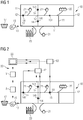
- the Fig. 1 illustrates by way of example and schematically a supply network 10 for supplying a number of consumers with drinking water. So it is a drinking water supply network.
- a supply network 10 for supplying a number of consumers with drinking water. So it is a drinking water supply network.
- the invention is not restricted to drinking water supply networks, but can also be applied to other types of supply networks.
- Fig. 1 is a measuring district, usually called "District Metering Area (DMA)" in technical jargon, which is part of a higher-level drinking water supply network.
- the measurement area shown can also be referred to as a pressure management zone (PMZ) , since the pressure in this zone is more advantageous by means of the present invention Way should be regulated.
- PMZ pressure management zone
- the supply network 10 shown has only a single inflow 13 and no outflows.
- the supply network 10 comprises a number of pipes 11, three or four pipes 11 meeting at several nodes 12 of the supply network 10. For clarity, in Fig. 1 not all existing pipes 11 and nodes 12 are referenced with reference symbols.
- a pump 16 which pumps the water from a water reservoir 17 into the supply network 10.
- a valve can also be provided which controls the inflow of water into the supply network 10.
- a valve instead of a pump can be sufficient, for example, if the water reservoir 17 is so high relative to the consumers connected to the supply network 10 that the water flows through the inflow 13 with so much pressure that the inflow only regulates the water but no longer has to be pumped into the supply network 10.
- Fig. 1 shows examples of some consumers that are connected to the drinking water supply network 10. Consumers are divided into different categories; in Fig. 1 Several single-family houses 21, an apartment building 22 and a factory 23 are shown by way of example. In reality, there are usually at least several dozen, often several hundred and sometimes several thousand loads in a DMA connected to a supply network. For clarity, in Fig. 1 by way of example only very few consumers connected to the supply network 10 are shown.
- FIG. 1 it is in Fig. 1 that is, the topology of the supply network 10, in particular the number and branches of the pipes 11, as well as the number and type of consumers connected to the supply network 10, are shown in a greatly simplified manner for improved illustration of the invention.
- the supply network 10 shown has no (explicit) drains. Nevertheless, there is an outflow of drinking water from the supply network 10 by means of the consumers. However, for practical reasons and for reasons of data protection law, the exact respective consumption levels of the consumers are not known.
- the supply network 10 also has three first sensors 14. These first sensors 14 are designed as flow meters or pressure meters and can measure the flow rate or the pressure of the drinking water through the pipes 11 at the respective locations in the supply network 10 where the first sensors 14 are located. The locations at which the first sensors 14 are located and for which the respective flow rate or pressure is measured are referred to as first locations 141.
- the object on which the invention is based now consists in optimally regulating the pressure in the supply network 10 during the operation of the supply network 10.
- the correct prediction of the instantaneous pressure at a second location 151 in the supply network 10 plays an important role here.
- the invention uses a corresponding device 30.
- a first embodiment of such a device 30 for pressure control in a supply network 10 is shown in FIG Fig. 2 .
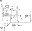
- the Fig. 3 a slightly modified exemplary embodiment of such a device 30.
- the two exemplary embodiments differ essentially in the use of a different target value during the learning of the self-learning system SS.
- FIG. 2 the same supply network 10 as that in Fig. 1 .
- the description of the supply network 10 and the consumers connected to it refer to the Fig. 1 referenced.
- the Fig. 2 shows in addition to the supply network 10 and the consumers connected to it also a device 30 for Pressure regulation of the drinking water in the supply network 10.
- the three first sensors 14 are connected to a first detection unit E1.
- the first acquisition unit E1 is designed to acquire and forward the flow rates and / or pressures measured by the first sensors 14 at the first locations 141.
- the Fig. 2 a second acquisition unit E2. Analogously to the first acquisition unit E1, this is designed to acquire the flow rate and / or pressure measured by a second sensor 15 at the second location 151 in the supply network 10 and, as soon as required in the process, to forward it to a corresponding point.
- the self-learning system SS is in the Fig. 2
- the first embodiment shown is connected to the first acquisition unit E1 and the second acquisition unit E2. These connections are in Fig. 1 marked as dashed lines.
- the first detection unit E1 supplies the input data, namely the measured flow rates and / or pressures at the first locations 141 in the supply network 10. Based on this, it is the task of the self-learning system SS to predict or predict an (expected) pressure at another location in the supply network. to determine. This other location is the already mentioned second location 151, namely the location at which the second sensor 15 is located.
- the pressure at the second location 151 determined by the self-learning system SS will generally not yet match the actual pressure at this location.
- the pressure determined by the self-learning system SS is compared with a target value.
- this target value is the flow rate and / or pressure actually measured at the second location.
- the measurement of the flow rate and / or pressure at this location is advantageously carried out with the second sensor 15.
- the pressure calculated or measured by the second sensor 15 is detected by the second detection unit E2 and forwarded to the self-learning system SS.
- the pressure measured or calculated by the second sensor 15 is then compared with the previously determined / predicted value in the self-learning system. If the agreement is too low - which, as indicated above, should be the rule in particular at the start of training - new flow and / or pressure values are measured by the first sensors 14.
- the self-learning system SS tries to predict the actual pressure at the second location 151 as accurately as possible for these new flow rates and / or pressures.
- the self-learning system SS will correctly predict the pressure at the second location 151 in the second run based on what has been learned from the first run without major problems. During operation, however, the self-learning system SS must be able to make a correct prediction for the pressure at the second 151 location for the most varied of flow rates and / or pressures at the first locations 141.
- the described steps of a run are therefore: measuring the flow rates and / or pressures at the first locations 141; Predicting the pressure at the second location 151; and comparing the predicted pressure with the actual measured pressure.
- the termination criterion can For example, for ten consecutive runs, the difference between the pressure determined by the self-learning system SS at the second location 151 and the pressure actually present (determined based on the measurement of the second sensor 15 located at the second location 151) is less than 5%, in particular less than 2%, preferably less than 1%, must be.
- the supply network 10 is operated, also referred to as the use phase.
- the flow rates and / or pressures at the first locations 141 in the supply network 10 are again measured. This is done by means of the first sensors 14.
- the measured values are recorded by the first recording unit E1 and forwarded to the self-learning system SS, which is also referred to as the "learned system” SS in the context of this patent application after the learning phase has ended.
- the forwarding of the flow rates and / or pressures detected by the first detection unit E1 to the trained system SS is in Fig. 1 marked with a solid line - to distinguish the dashed connection during the learning phase.
- the learned system SS now makes a prediction with regard to the expected pressure at the second based on the measured flow rates and / or pressures at the first locations 141 Location 151 in the supply network 10. This prediction is made by a prediction unit V.
- the pump 16 is then controlled accordingly. If it turns out, for example, that the pressure at the second location 151 is higher than it has to be for supplying the relevant consumers with drinking water, the pump 16 reduces its pumping capacity. This reduces the pressure in the supply network 10 and, in particular, also at the second location 151, as a result of which the wear on the components of the supply network 10, the energy consumption of the pump 16 and any background leakages in the supply network 10 are reduced. If, on the other hand, it turns out, for example, that the pressure at the second location 151 is lower than is required for fire hydrants placed in the vicinity of the second location 151, the pump 16 increases its pumping capacity. This ensures a water pressure at the second location 151 which, in the event that water has to be taken from a fire hydrant placed in this area, is high enough for the requirements associated therewith.
- the pressure in the supply network 10 can in principle be regulated even more optimally.
- the Fig. 3 shows a second embodiment of a device 30 for regulating the pressure in a supply network 10. It differs in the learning of the self-learning system SS from the device 30 of the first embodiment.
- the second exemplary embodiment only the measured flow rates and / or pressures at the first locations 141 are initially forwarded from the first detection unit E1 to the self-learning system SS during the learning phase.
- This in turn says or determines an expected pressure at the second location 151 in the supply network 10.
- This expected pressure it is not compared directly with the pressure determined at the second location 151, but with a simulated pressure at the second location 151. It is of great importance for successful learning of the self-learning system SS that the simulated flow rate at the second Location 151 is trustworthy, that is to say correct, since it represents the target value with which the self-learning system SS is learned. If the target value does not match reality, the learned system SS cannot logically map or predict reality correctly either.
- the simulation SIM is a hydraulic simulation.
- the pressures and other parameters e.g. flow rates, flow velocities, ...) in the supply network are simulated analytically or model-based on the basis of fluid mechanics.
- the challenge of a hydraulic simulation SIM is usually that it quickly becomes quite complex for supply networks that are relatively simple in topology.
- a series of input data IN is usually required for the hydraulic simulation SIM.
- the topology i.e. the arrangement and the course of the pipes 11 and nodes 12
- the flow rate and / or pressure at the inflow 13 into the supply network 10 the arrangement and type of consumers
- Substitute consumption profiles of the individual consumer types i.e. typical (or: representative) consumption profiles for the individual consumer types
- Properties of the pipes e.g. Coefficient of friction or inner diameter.
- the hydraulic simulation SIM simulates the expected pressure at the second location 151 and feeds this to the self-learning system SS.
- the simulated pressure at the second location 151 functions as a target value for the self-learning system SS and as a measure of how well the self-learning system SS has already been trained.
- the invention provides a method, a device and an arrangement with which the pressure in a supply network can be regulated in a simple manner with the aid of a self-learning system, the pressure not being measured at some locations in the supply network, but only by means of of the learned system is predicted.
Abstract
Die Erfindung betrifft ein Verfahren zur Druckregelung in einem Versorgungsnetz (10), wobei das Versorgungsnetz (10) dafür geeignet ist, Verbraucher mit einem Fluid zu versorgen. Das Versorgungsnetz (10) weist erste Sensoren (14) zur Messung der Durchflüsse und/oder der Drücke des Fluids an ersten Orten (141) im Versorgungsnetz (10) sowie eine Pumpe (16) zum Pumpen des Fluids oder ein Ventil zum Steuern eines Flusses des Fluids auf. Das Verfahren zur Druckregelung umfasst die folgenden Schritte: a) Messen der Durchflüsse und/oder Drücke des Fluids an den ersten Orten (141) im Versorgungsnetz (10) mittels der ersten Sensoren (14); b) Vorhersagen des Drucks an dem zweiten Ort (151) im Versorgungsnetz (10) mittels eines selbstlernenden Systems (SS) basierend auf den in Schritt a) gemessenen Durchflüssen bzw. Drücken, wobei das selbstlernende System (SS) dafür angelernt wurde, den Druck an einem vorgegebenen Ort im Versorgungsnetz (10) vorherzusagen; und c) Ansteuern der Pumpe (16) bzw. des Ventils basierend zumindest auch auf dem von dem angelernten System (SS) vorhergesagten Druck am zweiten Ort (151). Die Erfindung betrifft des Weiteren eine Vorrichtung (30) zur Druckregelung in einem Versorgungsnetz (10) und eine Anordnung umfassend ein Versorgungsnetz (10) und die erwähnte Vorrichtung (30).The invention relates to a method for regulating pressure in a supply network (10), the supply network (10) being suitable for supplying consumers with a fluid. The supply network (10) has first sensors (14) for measuring the flow rates and / or the pressures of the fluid at first locations (141) in the supply network (10) and a pump (16) for pumping the fluid or a valve for controlling a flow of the fluid. The method for pressure regulation comprises the following steps: a) measuring the flow rates and / or pressures of the fluid at the first locations (141) in the supply network (10) by means of the first sensors (14); b) Predicting the pressure at the second location (151) in the supply network (10) by means of a self-learning system (SS) based on the flow rates or pressures measured in step a), the self-learning system (SS) having been trained for the pressure predict at a predetermined location in the utility network (10); and c) controlling the pump (16) or the valve based at least also on the pressure at the second location (151) predicted by the learned system (SS). The invention also relates to a device (30) for regulating pressure in a supply network (10) and an arrangement comprising a supply network (10) and the aforementioned device (30).
Description
Die Erfindung betrifft ein Verfahren zur Druckregelung in einem Versorgungsnetz. Beispielhafte Anwendungen sind die Druckregelung in einem Trink- oder Abwassernetz oder in einem Gas- oder Fernwärmeversorgungsnetz.The invention relates to a method for regulating pressure in a supply network. Exemplary applications are pressure control in a drinking or sewage network or in a gas or district heating supply network.
Obwohl die vorliegende Erfindung nachfolgend mit Bezug auf Wasserversorgungsnetze beschrieben wird, ist sie genauso auf andere Versorgungsnetze, beispielsweise Gasversorgungsnetze oder Fernwärmeversorgungsnetze, anwendbar.Although the present invention is described below with reference to water supply networks, it is equally applicable to other supply networks, for example gas supply networks or district heating supply networks.
Der in einem Wasserversorgungsnetz herrschende hydraulische Druck ist ein wichtiges Qualitätsmerkmal. Für industrielle Großverbraucher und Feuerhydranten garantiert ein hoher Druck, dass eine große Wassermenge in kurzer Zeit aus dem Versorgungsnetz entnommen werden kann. An den Hausanschlüssen erlaubt ein ausreichend hoher Wasserdruck komplette Gebäude bis zur obersten Etage ohne zusätzliche Pumpeinrichtungen zuverlässig mit Trinkwasser zu versorgen.The hydraulic pressure prevailing in a water supply network is an important quality feature. For large industrial consumers and fire hydrants, high pressure guarantees that a large amount of water can be drawn from the supply network in a short time. A sufficiently high water pressure at the house connections allows entire buildings to be reliably supplied with drinking water up to the top floor without additional pumping equipment.
Auf der anderen Seite führt ein zu hoher Druck im Versorgungsnetz zu vorzeitiger Alterung und Versagen von Komponenten, beispielsweise durch Rohrleitungsbruch. Die dadurch verursachten Leckagen führen zu hohen Reparaturkosten, Wasserverlusten und in einigen Fällen zu weiteren Schäden an umliegenden Strukturen. Des Weiteren führt ein Überdruck zu einem erhöhten Wasserverlust durch Hintergrundleckagen. Solche Hintergrundleckagen sind in der Regel in jedem Wassernetz in gewissem Ausmaß vorhanden und haben einen kontinuierlichen Verlust von Trinkwasser zur Folge. Ein zu hoher Fließdruck erhöht außerdem die bei der Rohrströmung auftretenden Reibungsverluste. In Versorgungsnetzen, in denen der Druck durch Pumpen aufgebaut wird, führt eine Erhöhung des bereitgestellten Drucks unmittelbar zu einem erhöhten Energiebedarf der Pumpen.On the other hand, too high a pressure in the supply network leads to premature aging and failure of components, for example due to a broken pipe. The resulting leaks lead to high repair costs, water loss and, in some cases, further damage to surrounding structures. Furthermore, overpressure leads to increased water loss through background leakage. Such background leaks tend to be present to some extent in any water network and result in continual loss of drinking water. Too high a flow pressure also increases the friction losses occurring in the pipe flow. In supply networks in which the pressure is built up by pumps, an increase in the pressure provided leads directly to an increased energy requirement of the pumps.
Betreiber von Versorgungsnetzen stehen daher vor der Herausforderung, zwischen den genannten beiden entgegenlaufenden Anforderungen einen Kompromiss bezüglich des bereitgestellten hydraulischen Drucks in dem Versorgungsnetz zu finden. Diese Entscheidung wird zusätzlich dadurch erschwert, dass der im Betrieb herrschende Druck stark durch die Abnahmelast beeinflusst wird, die starken Schwankungen ausgesetzt sein und oft nicht zuverlässig gemessen oder vorhergesagt werden kann. Diese Abnahmeschwankungen sowie Schaltvorgänge von Pumpen und Ventilen können weiterhin zu kurzzeitigen Druckspitzen im Versorgungsnetz führen, die eine schädliche Wirkung auf Netzkomponenten haben können und häufig die Ursache von plötzlich auftretenden Leckagen darstellen.Operators of supply networks are therefore faced with the challenge of finding a compromise between the aforementioned two opposing requirements with regard to the hydraulic pressure made available in the supply network. This decision is made even more difficult by the fact that the pressure prevailing during operation is strongly influenced by the acceptance load, which is exposed to strong fluctuations and often cannot be reliably measured or predicted. These fluctuations in consumption as well as switching operations of pumps and valves can also lead to brief pressure peaks in the supply network, which can have a harmful effect on network components and are often the cause of sudden leaks.
In vielen Wasserversorgungsnetzen wird heutzutage durch Hochbehälter oder ständig laufende Pumpen gezielt ein kontinuierlich hoher Druck bereitgestellt. Die Auslegung der Netzkomponenten wird schon bei der Planung bewusst überdimensioniert. Der Überdruck im Versorgungsnetz wird an den Verbrauchsstellen durch Druckreduzierungseinrichtungen auf ein für die Verbraucher sinnvolles Maß reduziert. Die durch den langfristigen Betrieb mit hohem Druck vorstehend aufgeführten Nachteile werden vielfach in Kauf genommen.In many water supply networks nowadays a continuously high pressure is provided in a targeted manner by means of elevated tanks or continuously running pumps. The design of the network components is deliberately oversized at the planning stage. The overpressure in the supply network is reduced to a level that makes sense for the consumer at the points of consumption by means of pressure reducing devices. The disadvantages listed above due to long-term operation at high pressure are often accepted.
Erst in der jüngeren Vergangenheit wurden unter dem Schlagwort "Pressure Management" Ansätze entwickelt, um den im Wasserverteilnetz herrschenden Druck gezielt an die Anforderungen der Verbraucher anzupassen und damit zu hohe Drücke samt den damit einhergehenden Nachteilen zu vermeiden. Zu den dabei entwickelten Techniken gehört die Unterteilung des Versorgungsnetzes in Druckzonen (englisch: pressure management zones, PMZ), in denen der Druck an den Zuflüssen durch gezielte Steuerung von Ventilen oder Pumpen auf ein Mindestmaß reduziert wird. Zur Auslegung der Drucksteuerung werden dabei Kenntnisse über die Netzstruktur, die topographischen Gegebenheiten der Druckzone sowie über Anzahl und Art der angeschlossenen Verbraucher herangezogen. Um auf die durch wechselnden Verbrauch verursachten dynamischen Druckschwankungen reagieren zu können, werden inzwischen auch online gemessene Druckwerte in der Zone für die Drucksteuerung verwendet.It is only in the recent past that approaches have been developed under the catchphrase "pressure management" to adapt the pressure prevailing in the water distribution network to the requirements of the consumer and thus avoid excessively high pressures and the associated disadvantages. The technologies developed in this context include the subdivision of the supply network into pressure management zones (PMZ), in which the pressure at the inflows is reduced to a minimum through targeted control of valves or pumps. To design the pressure control, knowledge of the network structure, the topographical conditions of the pressure zone and the number and type of connected consumers are used. To get on by changing To be able to react to dynamic pressure fluctuations caused by consumption, pressure values measured online in the zone are now also used for pressure control.
Die europäische Patentanmeldung
In manchen Fällen ist die Erstellung eines solchen Simulationsmodells jedoch relativ aufwändig, beispielsweise bei einem komplexen Verlauf der Rohrleitungen des Versorgungsnetzes, oder es liegen schier nicht genügend Informationen bezüglich der Topologie des Versorgungsnetzes und der mit dem Versorgungsnetz verbundenen Verbraucher vor. In anderen Fällen ist es zwar möglich, ein entsprechendes Simulationsmodell aufzustellen und die Daten zu reduzieren. Dennoch kann die Rekonstruktion des zweiten Druck- oder Durchflusswertes trotz der Reduktion der Daten aus dem Simulationsmodell länger als für die Ansteuerung der Pumpe und/oder des Ventils gewünscht dauern.In some cases, however, the creation of such a simulation model is relatively complex, for example in the case of a complex course of the pipelines of the supply network, or there is almost not enough information available regarding the topology of the supply network and the consumers connected to the supply network. In other cases it is possible to set up a corresponding simulation model and reduce the data. Still, the reconstruction can of the second pressure or flow value take longer than desired for the control of the pump and / or the valve despite the reduction of the data from the simulation model.
Vor diesem Hintergrund besteht eine Aufgabe der vorliegenden Erfindung darin, ein alternatives Konzept zur Druckregelung in einem Versorgungsnetz bereitzustellen, das insbesondere eine schnelle Ansteuerung der Pumpe und/oder des Ventils ermöglicht.Against this background, one object of the present invention is to provide an alternative concept for regulating pressure in a supply network, which in particular enables the pump and / or the valve to be controlled quickly.
Die Erfindung ergibt sich aus den Merkmalen der unabhängigen Ansprüche. Vorteilhafte Weiterbildungen und Ausgestaltungen sind Gegenstand der abhängigen Ansprüche. Weitere Merkmale, Anwendungsmöglichkeiten und Vorteile der Erfindung ergeben sich aus der nachfolgenden Beschreibung und den Abbildungen.The invention results from the features of the independent claims. The dependent claims relate to advantageous developments and refinements. Further features, possible applications and advantages of the invention emerge from the following description and the figures.
Demgemäß wird ein Verfahren zur Druckregelung in einem Versorgungsnetz bereitgestellt. Das Versorgungsnetz ist dafür geeignet und dazu ausgelegt, Verbraucher mit einem Fluid zu versorgen. Das Versorgungsnetz weist erste Sensoren zur Messung der Durchflüsse und/oder der Drücke des Fluids an ersten Orten im Versorgungsnetz auf. Ferner weist das Versorgungswerk eine Pumpe zum Pumpen des Fluids oder ein Ventil zum Steuern eines Flusses des Fluids auf. Das Verfahren zur Druckregelung weist die folgenden Schritte auf:
- a) Messen der Durchflüsse und/oder Drücke des Fluids an den ersten Orten im Versorgungsnetz mittels der ersten Sensoren,
- b) Vorhersagen des Drucks an dem zweiten Ort im Versorgungsnetz mittels eines selbstlernenden Systems basierend auf den in Schritt a) gemessenen Durchflüssen bzw. Drücken, wobei das selbstlernende System dafür angelernt wurde, den Druck an einem vorgegebenen Ort im Versorgungsnetz vorherzusagen, und
- c) Ansteuern der Pumpe bzw. des Ventils basierend zumindest auch auf dem von dem angelernten System vorhergesagten Druck am zweiten Ort.
- a) measuring the flow rates and / or pressures of the fluid at the first locations in the supply network by means of the first sensors,
- b) Predicting the pressure at the second location in the supply network by means of a self-learning system based on the flow rates or pressures measured in step a), the self-learning system having been trained to predict the pressure at a predetermined location in the supply network, and
- c) controlling the pump or the valve based at least also on the pressure at the second location predicted by the learned system.
Die Erfinder haben erkannt, dass sich für die Druckregelung in einem Versorgungsnetz ein selbstlernendes System in vorteilhafter Weise verwenden lässt. In einer ersten Phase wird das selbstlernende System angelernt, den Druck an einem vorgegebenen Ort im Versorgungsnetz vorhersagen zu können. Nach der Anlernphase wird das angelernte System während des Betriebs des Versorgungsnetzes verwendet. Hierfür sagt das angelernte System basierend auf während des Betriebs tatsächlich gemessenen Durchflüssen und/oder Drücken den Druck an einem bestimmten Ort im Versorgungsnetz voraus. Der Gedanke ist, dass der vorhergesagte Wert den tatsächlichen Druck korrekt angibt. Dank der Vorhersage des angelernten Systems ist also insbesondere keine Messung des Durchflusses und/oder Drucks am zweiten Ort notwendig, um den Druck am zweiten Ort zu kennen (vorausgesetzt, die Vorhersage des angelernten Systems ist korrekt).The inventors have recognized that a self-learning system can advantageously be used for pressure regulation in a supply network. In a first phase, the self-learning system is taught to be able to predict the pressure at a given location in the supply network. After the learning phase, the learned system is used during operation of the supply network. For this purpose, the learned system predicts the pressure at a specific location in the supply network based on the flow rates and / or pressures actually measured during operation. The idea is that the predicted value correctly indicates the actual pressure. Thanks to the prediction of the learned system, in particular no measurement of the flow rate and / or pressure at the second location is necessary in order to know the pressure at the second location (provided that the prediction of the learned system is correct).
Daraus ergeben sich mehrere Vorteile. Ein erster Vorteil besteht darin, dass es möglich ist, den Druck an Orten im Versorgungsnetz zu kennen, an denen kein Sensor platziert ist und für dessen Kenntnis keine Messung an besagtem Ort nötig ist. Es ist - wie noch im Detail später beschrieben werden wird - unter Umständen vorteilhaft, während des Anlernens des selbstlernenden Systems den Druck und/oder den Durchfluss an dem entsprechenden "zweiten" Ort zu messen. Auch hierfür gibt es jedoch Alternativen, falls der zweite Ort z.B. für eine direkte Messung schwer oder gar nicht zugänglich ist. In jedem Fall ist für die Druckregelegung an sich kein Sensor am zweiten Ort erforderlich, da mithilfe des angelernten Systems der Druck an der dortigen Stelle vorhergesagt wird.This has several advantages. A first advantage consists in the fact that it is possible to know the pressure at locations in the supply network where no sensor is placed and where no measurement at the said location is necessary for knowing this. As will be described in detail later, it is sometimes advantageous to measure the pressure and / or the flow rate at the corresponding "second" location while the self-learning system is being taught. However, there are alternatives for this, too, if the second location is e.g. is difficult or impossible to access for a direct measurement. In any case, no sensor is required at the second location for pressure control, as the pressure at that location is predicted with the help of the learned system.
Ein zweiter Vorteil des erfindungsgemäßen Verfahrens besteht darin, dass die Bestimmung des Drucks am zweiten Ort schnell erfolgen kann. Im Gegensatz beispielsweise zu einer analytischen oder modellbasierten Simulation des Versorgungsnetzes, die bereits bei einer wenig komplexen Topologie des Versorgungsnetzes und einer geringen Anzahl von Verbrauchern sehr schnell sehr rechenintensiv und damit zeitaufwändig wird, zeichnet sich ein angelerntes System unter anderem darin aus, dass es für eingegebene Eingangsdaten - hier die gemessenen Durchflüsse und/oder Drücke der ersten Sensoren - in der Regel sehr schnell die geforderte Ausgabe - hier den Druck an dem zweiten Ort - ausgibt. Somit liegt quasi "online" und ohne Zeitverzögerung nach Messung der Durchflüsse und/oder Drücke an den ersten Orten auch der Druck an dem zweiten Ort vor. Dies ist für ein Regelungsverfahren, wie das vorliegende Verfahren zur Regelung des Drucks in einem Versorgungsnetz, von nicht zu unterschätzender Relevanz.A second advantage of the method according to the invention is that the pressure can be determined quickly at the second location. In contrast to an analytical one, for example or model-based simulation of the supply network, which is very computationally intensive and therefore time-consuming even with a less complex topology of the supply network and a small number of consumers, a learned system is characterized, among other things, by the fact that it is used for input data - here the measured flow rates and / or pressures of the first sensors - usually very quickly the required output - here the pressure at the second location - outputs. Thus, the pressure at the second location is also available quasi “online” and without a time delay after measuring the flow rates and / or pressures at the first locations. This is of relevance for a control method such as the present method for controlling the pressure in a supply network, which should not be underestimated.
Eine Vorhersage des Drucks ist in der Regel nur für denjenigen Ort möglich, für den das selbstlernende System auch trainiert wurde. Es ist allerdings möglich, das selbstlernende System für die Vorhersage des Drucks an mehreren Orten des Versorgungsnetzes zu trainieren. Die Anzahl an Messpunkten im Netz muss nicht zwangsläufig größer als die derjenigen Orte, deren Drücke vorhergesagt werden, sein, ist es in der Regel jedoch.A prediction of the pressure is usually only possible for the location for which the self-learning system was also trained. However, it is possible to train the self-learning system to predict the pressure at several locations in the supply network. The number of measuring points in the network does not necessarily have to be greater than the number of locations whose pressures are predicted, but it is usually.
Das beschriebene Verfahren lässt sich allgemein auf jede Art von Versorgungsnetzen anwenden, in dem ein Druck eines Fluids zu regulieren ist. Unter einem Fluid wird jede Art von Flüssigkeit oder Gas verstanden. In dem Fall, dass es sich bei dem Fluid um Wasser handelt, ist das Versorgungsnetz insbesondere ein Trinkwasserversorgungs- oder Abwassernetz. In dem Fall, dass es sich bei dem Fluid beispielsweise um Erdgas handelt, ist das Versorgungsnetz insbesondere ein Gasversorgungsnetz. In dem Fall, dass es sich bei dem Versorgungsnetz um ein Fernwärmeversorgungsnetz handelt, ist das Überträgermedium, also das Fluid, meist Heißwasser, seltener auch Dampf.The method described can generally be applied to any type of supply network in which the pressure of a fluid is to be regulated. A fluid is understood to mean any type of liquid or gas. In the event that the fluid is water, the supply network is in particular a drinking water supply or sewage network. In the event that the fluid is, for example, natural gas, the supply network is in particular a gas supply network. In the event that the supply network is a district heating supply network, the transfer medium, that is to say the fluid, is mostly hot water, and more rarely steam.
Das Versorgungsnetz umfasst insbesondere eine Reihe von Rohren, die auch als Rohrleitungen oder nur als Leitungen bezeichnet werden. Die Rohre sind dafür da, das Fluid zu den Verbrauchern und gegebenenfalls wieder von ihnen weg zu leiten. Die Rohre sind also dafür ausgestaltet, von dem Fluid durchströmt zu werden.The supply network includes in particular a number of pipes, which are also referred to as pipelines or just as lines. The pipes are there to guide the fluid to the consumers and, if necessary, away from them again. The tubes are therefore designed for the fluid to flow through.
Im Rahmen dieser Patentanmeldung wird unter dem Durchfluss an einem bestimmten Ort im Versorgungsnetz das Volumen des Fluids verstanden, das pro Zeitspanne durch den Querschnitt des Rohrs an dem entsprechenden Ort fließt. Der Querschnitt des Rohrs ist dabei durch dessen Innerdurchmesser festgelegt. Der Durchfluss wird auch als "Volumenstrom" oder "Durchflussrate" bezeichnet. Er hat die SI-Einheit m3/h. Mit dem Durchfluss ist im Rahmen dieser Patentanmeldung also ein Wert gemeint, der den Durchfluss charakterisiert und quantifiziert. Er kann folglich auch als "Durchflusswert" bezeichnet werden.In the context of this patent application, the flow rate at a specific location in the supply network is understood to mean the volume of the fluid that flows through the cross section of the pipe at the corresponding location over a period of time. The cross-section of the pipe is determined by its inner diameter. The flow is also referred to as "volume flow" or "flow rate". It has the SI unit m 3 / h. In the context of this patent application, the flow rate means a value that characterizes and quantifies the flow rate. It can therefore also be referred to as the "flow rate".
Der Durchfluss wird mittels Durchflussmessern gemessen. Ein Durchflussmesser weist in der Regel zwei Hauptkomponenten auf: der eigentliche Messaufnehmer, der als Durchflusssensor dient, und ein Auswerte- und Speiseteil, das auch als Transmitter oder Messumformer bezeichnet wird. Die Durchflussmesser werden im Rahmen dieser Patentanmeldung auch als "Sensor" bezeichnet.The flow is measured using flow meters. A flow meter usually has two main components: the actual measuring sensor, which serves as a flow sensor, and an evaluation and supply part, which is also referred to as a transmitter or measuring transducer. The flow meters are also referred to as “sensors” in the context of this patent application.
In dem Fall, dass es sich bei dem Fluid im Versorgungsnetz um eine Flüssigkeit handelt, wird im Rahmen dieser Patentanmeldung unter dem Druck an einem bestimmten Ort im Versorgungsnetz der hydrodynamische Druck der Flüssigkeit an diesem Ort verstanden. Der hydrodynamische Druck ist nicht direkt messbar, lässt sich aber bei verlustfreier, horizontaler und stationärer Strömung aus der Messung der Differenz zwischen Totaldruck und statischem Druck bestimmen, beispielsweise mit einer Prandtlsonde, die eine Kombination aus einem Pitotrohr und einer statischen Drucksonde ist. Unter der Messung des Drucks des Fluids wird also im Fall einer Flüssigkeit insbesondere die indirekte Ermittlung des Drucks mittels einer Prandtlsonde verstanden.In the event that the fluid in the supply network is a liquid, in the context of this patent application the pressure at a specific location in the supply network is understood to be the hydrodynamic pressure of the liquid at this location. The hydrodynamic pressure cannot be measured directly, but with loss-free, horizontal and steady flow, it can be determined by measuring the difference between total pressure and static pressure, for example with a Prandtl probe, which is a combination of a pitot tube and a static pressure probe. In the case of a liquid, the measurement of the pressure of the fluid is in particular understood the indirect determination of the pressure by means of a Prandtl probe.
In dem Fall, dass es sich bei dem Fluid im Versorgungsnetz um ein Gas oder Gasgemisch handelt, wird unter dem Druck die resultierende Kraft, die sich aus der Summe aller durch das Gas oder Gasgemisch wirkenden Kräfte in alle Richtungen ergibt, verstanden. Es ist also auch hier, analog zum hydrodynamischen Druck einer strömenden Flüssigkeit, der Druck des strömenden Gases in Strömungsrichtung relevant.In the event that the fluid in the supply network is a gas or gas mixture, the pressure is understood to mean the resultant force that results from the sum of all forces acting in all directions by the gas or gas mixture. Here, too, analogous to the hydrodynamic pressure of a flowing liquid, the pressure of the flowing gas in the direction of flow is relevant.
Ist der hydrodynamische Druck einer Flüssigkeit an einer Stelle bekannt, kann daraus die Geschwindigkeit der Flüssigkeit und daraus der Durchfluss berechnet werden. Umgekehrt kann aus einem bekannten Durchfluss an einem Ort der (relative) Druck an diesem Ort berechnet werden. Ist an einem Ort im Versorgungsnetz ferner der absolute Druck bekannt, kann in der Regel an jedem Ort im Versorgungsnetz der relative Druck in einen absoluten Druck umgerechnet werden.If the hydrodynamic pressure of a liquid is known at a point, the speed of the liquid and from this the flow can be calculated. Conversely, the (relative) pressure at that location can be calculated from a known flow rate at a location. If the absolute pressure is also known at a location in the supply network, the relative pressure can generally be converted into an absolute pressure at any location in the supply network.
Folglich kann das selbstlernende System sowohl mit gemessenen Durchflüssen an den ersten Orten als auch mit gemessen Drücken angelernt werden. Es jedoch vorteilhaft, wenn zumindest einer der ersten Sensoren tatsächlich einen absoluten Druck misst, da dann das selbstlernende System für den zweiten Ort auch einen absoluten Druck bestimmen kann. Ebenso ist es für den Betrieb des Versorgungsnetzes, also nach abgeschlossener Anlernphase des selbstlernen Systems, vorteilhaft, wenn zumindest einer der ersten Sensoren tatsächlich einen absoluten Druck misst, da auch (nur) dann das angelernte System für den zweiten Ort einen absoluten Druck vorhersagen kann.As a result, the self-learning system can be trained both with measured flow rates at the first locations and with measured pressures. However, it is advantageous if at least one of the first sensors actually measures an absolute pressure, since the self-learning system can then also determine an absolute pressure for the second location. It is also advantageous for the operation of the supply network, i.e. after the learning phase of the self-learning system has been completed, if at least one of the first sensors actually measures an absolute pressure, since (only) then the learned system can also predict an absolute pressure for the second location.
Das selbstlernende System ist vorzugsweise als künstliches neuronales Netz ausgestaltet. Es weist künstliche Neuronen auf, die auf einer oder mehreren Schichten liegen und miteinander verbunden sind. Ein künstliches Neuron kann mehrere Eingaben verarbeiten und entsprechend über seine Aktivierung reagieren. Dazu werden die Eingaben gewichtet an eine Ausgabefunktion übergeben, welche die Neuronenaktivierung berechnet. Die Gewichtungen werden während der Anlernphase des selbstlernenden Systems kontinuierlich angepasst, bis die Ausgabe für eine bestimmte Eingabe möglichst genau mit einem Zielwert übereinstimmt.The self-learning system is preferably designed as an artificial neural network. It has artificial neurons that lie on one or more layers and are connected to each other. An artificial neuron can process several inputs and react accordingly when activated. For this purpose, the inputs are weighted to an output function passed, which calculates the neuron activation. The weightings are continuously adapted during the learning phase of the self-learning system until the output for a specific input matches a target value as closely as possible.
Der Fachmann weiß, wie er ein geeignetes selbstlernendes System konfiguriert. Ein Beispiel für ein geeignetes Programmiergerüst ist TensorFlow. TensorFlow ist ein Programmiergerüst (englisch: Framework) zur datenstromorientierten Programmierung. Es wird z.B. aus Python-Programmen heraus benutzt und ist in Python und C++ implementiert. TensorFlow ist insbesondere für selbstlernende Systeme im Bereich des maschinellen Lernens populär. TensorFlow wurde ursprünglich vom Google-Brain-Team für den Google-internen Bedarf entwickelt und später unter der Apache-2.0-Open-Source-Lizenz veröffentlicht. In der Forschung und im Produktivbetrieb wird TensorFlow derzeit von verschiedenen Teams in kommerziellen Google-Produkten wie Spracherkennung, Gmail, Google Fotos und Google Suche verwendet. Auch der Kartendienst Maps wird durch Analyse der von Street View aufgenommenen Fotos, die mit Hilfe einer auf TensorFlow basierenden künstlichen Intelligenz analysiert werden, verbessert. Viele dieser Produkte nutzten früher die Vorgängersoftware DistBelief.The person skilled in the art knows how to configure a suitable self-learning system. An example of a suitable programming framework is TensorFlow. TensorFlow is a programming framework for data stream-oriented programming. It is used, for example, from Python programs and is implemented in Python and C ++. TensorFlow is particularly popular for self-learning systems in the field of machine learning. TensorFlow was originally developed by the Google Brain team for Google's internal needs and was later published under the Apache 2.0 open source license. In research and production, TensorFlow is currently used by various teams in commercial Google products such as speech recognition, Gmail, Google Photos and Google Search. The map service Maps is also improved by analyzing the photos taken by Street View, which are analyzed with the help of an artificial intelligence based on TensorFlow. Many of these products used the previous software, DistBelief.
Das Anlernen des selbstlernenden Systems umfasst die folgenden Schritte:
In einem ersten Schritt i) werden an mehreren ersten Orten im Versorgungsnetz mittels erster Sensoren, wovon sich vorzugsweise an jedem ersten Ort (auch: Messort) sich einer befindet, der jeweilige Druck gemessen. Alternativ oder zusätzlich kann, wie oben beschrieben, auch der Durchfluss gemessen werden. Die Menge an gemessenen Drücken und/oder Durchflüssen an den verschiedenen ersten Orten bildet die Eingangsdaten für das selbstlernende System.The learning of the self-learning system comprises the following steps:
In a first step i), the respective pressure is measured at several first locations in the supply network by means of first sensors, one of which is preferably located at each first location (also: measurement location). Alternatively or additionally, as described above, the flow rate can also be measured. The amount of measured pressures and / or flow rates at the various first locations forms the input data for the self-learning system.
Im zweiten Schritt ii) bestimmt das selbstlernende System, also in der Regel das künstliche neuronale Netz, einen Ausgabewert basierend auf den in Schritt i) gesammelten Eingangsdaten. Bei dem Ausgabewert handelt es sich vorliegend konkret um den Druck an dem entsprechenden Ort, dem sogenannten zweiten Ort.In the second step ii) the self-learning system, that is to say usually the artificial neural network, determines an output value based on the input data collected in step i). In the present case, the output value is specifically the pressure at the corresponding location, the so-called second location.
Im dritten Schritt iii) wird der von dem selbstlernenden System bestimmte Druck am zweiten Ort mit einem Zielwert verglichen und in einem vierten Schritt iv) das selbstlernende System unter Berücksichtigung des im vorigen Schritt angestellten Vergleichs angepasst. Das Lernverfahren, mit dem das selbstlernende System angelernt (oder: trainiert) wird, den Druck an einem bestimmten Ort korrekt vorherzusagen, ist als ein überwachtes Lernen (englisch: supervised learning) ausgestaltet. Beim überwachten Lernen wird dem künstlichen neuronalen Netz ein Eingangsmuster gegeben und die Ausgabe, die das neuronale Netz in seinem aktuellen Zustand produziert, mit dem Wert verglichen, den es eigentlich ausgeben soll. Durch Vergleich von Soll- und Istausgabe kann auf die vorzunehmenden Änderungen der Netzkonfiguration geschlossen werden. Bei einlagigen neuronalen Netzen kann die Delta-Regel (auch Perzeptron-Lernregel) angewendet werden. Mehrlagige neuronale Netze werden in der Regel mit Fehlerrückführung (englisch: Backpropagation) trainiert, was eine Verallgemeinerung der Delta-Regel darstellt.In the third step iii) the pressure determined by the self-learning system at the second location is compared with a target value and in a fourth step iv) the self-learning system is adapted taking into account the comparison made in the previous step. The learning process with which the self-learning system is trained (or: trained) to correctly predict the pressure at a certain location is designed as supervised learning . In supervised learning, the artificial neural network is given an input pattern and the output that the neural network produces in its current state is compared with the value that it should actually output. By comparing the target and actual output, conclusions can be drawn about the changes to be made to the network configuration. The delta rule (also known as the perceptron learning rule) can be applied to single-layer neural networks. Multi-layer neural networks are usually trained with error feedback (English: backpropagation) , which is a generalization of the delta rule.
In einer ersten Alternative basiert der Zielwert auf einem tatsächlich gemessenen Durchfluss und/oder Druck an demjenigen Ort, an dem das selbstlernende System den Druck vorherzusagen hat. Mit anderen Worten wird der von dem selbstlernenden System vorhergesagte Druck an dem zweiten Ort mit dem tatsächlich vorliegenden Druck, gemessen mit bzw. erhalten von einem entsprechenden Sensor, verglichen.In a first alternative, the target value is based on an actually measured flow rate and / or pressure at that location at which the self-learning system has to predict the pressure. In other words, the pressure predicted by the self-learning system at the second location is compared with the pressure actually present, measured with or obtained from a corresponding sensor.
Diese Wahl des Zielwertes hat den Vorteil, dass der Zielwert schnell und präzise erhalten werden kann. Der Zielwert ist schnell erhältlich, da hierfür lediglich eine Messung des Durchflusses und/oder Drucks mit einem entsprechenden Sensor notwendig ist. Der mittels eines Sensors gemessene Zielwert ist, abhängig von der Güte und Qualität des Sensors, von hoher Präzision, da er direkt gemessen wird und somit etwaige Fehlerquellen minimal sind.This choice of the target value has the advantage that the target value can be obtained quickly and precisely. The target value can be obtained quickly as it is only a measurement of the Flow and / or pressure with a corresponding sensor is necessary. The target value measured by means of a sensor is, depending on the quality and quality of the sensor, of high precision, since it is measured directly and any sources of error are therefore minimal.
In einer zweiten Alternative wird der Zielwert nicht direkt gemessen, sondern mittels einer Simulation bestimmt. Der von dem selbstlernenden System vorhergesagte Druck an einem bestimmten Ort wird also mit einem mittels einer Simulation berechneten Druck an dem genannten Ort verglichen. Eine entscheidende Bedingung dafür, dass die Anlernphase erfolgreich ist und, vor allem, dass das angelernte System erfolgreich im Betrieb eingesetzt werden kann, ist die Qualität der Simulation. Da die Drücke, die die Simulation berechnet, als Zielwerte während des Trainings des selbstlernenden Systems verwendet werden, sollten die simulierten Drücke die Realität mit hoher Verlässlichkeit und Präzision wiedergeben. Mit anderen Worten wird darauf vertraut, dass die Simulation imstande ist, für die unterschiedlichsten Eingangsdaten den tatsächlichen Druckwert exakt zu berechnen.In a second alternative, the target value is not measured directly, but determined by means of a simulation. The pressure at a specific location predicted by the self-learning system is therefore compared with a pressure calculated by means of a simulation at the named location. A decisive condition for the learning phase to be successful and, above all, for the learned system to be able to be used successfully in operation, is the quality of the simulation. Since the pressures that the simulation calculates are used as target values during training of the self-learning system, the simulated pressures should reflect reality with high reliability and precision. In other words, it is trusted that the simulation is able to precisely calculate the actual pressure value for the most varied of input data.
Der Vorteil eines analytisch oder modellbasiert berechneten Zielwerts besteht darin, dass es während der Anlernphase keines Sensors und keiner Durchfluss- oder Druckmessung am entsprechenden Ort bedarf. Da es auch während des Betriebs des Versorgungsnetzes keiner Messung am entsprechenden (zweiten) Ort bedarf, kann also bei Simulierung des Zielwerts gänzlich auf eine Platzierung und Verwendung eines Sensors am zweiten Ort verzichtet werden.The advantage of an analytically or model-based calculated target value is that there is no need for a sensor or flow or pressure measurement at the relevant location during the learning phase. Since no measurement is required at the corresponding (second) location during operation of the supply network, there is no need to place and use a sensor at the second location when simulating the target value.
Für den Fall, dass das Fluid Wasser ist, spricht man bei der Simulation auch von einer hydraulischen Simulation.In the event that the fluid is water, the simulation is also referred to as a hydraulic simulation.
Im Allgemeinen ist die Simulation umso präziser, je zahlreicher und präziser ihr Input, das heißt ihre Eingangsdaten sind. Als Eingangsdaten für ein Versorgungsnetz kommen zum Beispiel die Topologie des Netzes infrage. Darunter versteht man die Anordnung und Beschaffenheit der Rohre einschließlich der Platzierung der Knoten, in dem sich drei oder mehr Rohre treffen. Weitere Eingangsdaten, die benötigt werden, sind die Orte, an denen mit dem Versorgungsnetz verbundene Verbraucher platziert sind, sowie die Art der Verbraucher. Weitere Eingangsdaten, die für eine präzise Simulation benötigt werden oder zumindest von großem Nutzen sind, sind Eigenschaften der Rohre wie beispielsweise deren Durchmesser oder deren Fließwiderstände. Schließlich sind irgendeine Art von Ersatzverbrauchsprofile für die verschiedenen Arten von Verbrauchern nötig. Da aus praktischen und datenschutzrechtlichen Gründen nicht die tatsächlichen Verbräuche der Verbraucher als Input genommen werden können, werden in der Regel repräsentative Verbräuche, sogenannte Ersatzverbrauchsprofile, der Simulation zugrunde gelegt. Es können beispielsweise je ein Ersatzverbrauchsprofil für ein Einfamilienhaus, Mehrfamilienhaus (mit Angabe der Wohneinheiten), Kleingewerbe, Krankenhaus, etc. verwendet werden.In general, the more numerous and precise its input, that is, its input data, the more precise the simulation. The topology of the network, for example, can be used as input data for a supply network. This means the arrangement and nature of the pipes including the placement of the node in which three or more pipes meet. Further input data that are required are the locations at which consumers connected to the supply network are placed and the type of consumer. Other input data that are required or at least very useful for a precise simulation are properties of the pipes such as their diameter or their flow resistance. Finally, some kind of substitute consumption profiles are needed for the different kinds of consumers. Since, for practical and data protection reasons, the actual consumption of the consumer cannot be taken as input, the simulation is usually based on representative consumption, so-called substitute consumption profiles. For example, a substitute consumption profile can be used for a single-family house, multi-family house (with details of the residential units), small businesses, hospitals, etc.
Vorteilhafterweise werden die Zielwerte für die entsprechenden Eingangsdaten während der Anlernphase rasch zur Verfügung gestellt, da hierdurch die Dauer der Anlernphase minimiert werden kann. Hierfür kann es von Vorteil sein, die Eingangsdaten der Simulation vor der Bestimmung des Zielwerts zu reduzieren. Dies kann z.B. mittels einer Reihenentwicklung vorgenommen werden. Dem Fachmann sind entsprechende Techniken und Vorgehensweisen hierfür bekannt; lediglich beispielhaft wird in diesem Zusammenhang die Hauptkomponentenanalyse erwähnt.The target values for the corresponding input data are advantageously made available quickly during the learning phase, since this allows the duration of the learning phase to be minimized. For this it can be advantageous to reduce the input data of the simulation before determining the target value. This can e.g. be made by means of a series development. Corresponding techniques and procedures for this are known to the person skilled in the art; The principal component analysis is only mentioned as an example in this context.
Ändert sich die Topologie des Netzes in signifikantem Ausmaß, etwa durch signifikante Änderungen bei den Verbrauchern oder durch Änderungen bei den verlegten Rohren, muss das selbstlernende System neu angelernt werden. Das selbstlernende System kann aber in der Regel mit den Parametern, z.B. Gewichtungen, des bisherigen angelernten Systems vorbelegt werden, so dass gewöhnlicherweise nur eine relativ schnelle und unaufwändige Aktualisierung der Parameter, also eine verkürzte Anlernphase, notwendig ist.If the topology of the network changes to a significant extent, for example due to significant changes in the consumers or due to changes in the installed pipes, the self-learning system must be taught in again. The self-learning system can, however, as a rule be pre-assigned the parameters, for example weightings, of the previously learned system, so that usually only a relatively quick and inexpensive Updating the parameters, i.e. a shortened learning phase, is necessary.
Zurück zum Verfahren, das selbstlernende System anzulernen: Die genannten Schritte i) bis iv) werden so oft wiederholt, bis ein vorgegebenes Abbruchkriterium erreicht ist. Das Abbruchkriterium kann zum Beispiel darin bestehen, dass die Differenz zwischen dem von dem selbstlernenden System bestimmten Druck an einem bestimmten Ort und dem "wahren" Druck an diesem Ort - also dem Zielwert - kleiner als ein vorgegebener Schwellwert ist. Mit anderen Worten sollen beide Werte übereinstimmen oder sich nur unwesentlich unterscheiden. Um sicherzugehen, dass das selbstlernende System robust ist und über einen breiten Bereich von Eingangsdaten zuverlässig den wahren Durchfluss an dem entsprechenden Ort vorhersagt, kann das Abbruchkriterium ferner beinhalten, dass der Durchschnitt über eine vorbestimmte Anzahl an Iteration den vorgegebenen Schwellwert für die Differenz unterschreiten soll.Back to the process of learning the self-learning system: The aforementioned steps i) to iv) are repeated until a predetermined termination criterion is reached. The termination criterion can consist, for example, in the fact that the difference between the pressure determined by the self-learning system at a certain location and the "true" pressure at this location - that is to say the target value - is less than a predetermined threshold value. In other words, the two values should match or differ only insignificantly. In order to ensure that the self-learning system is robust and reliably predicts the true flow rate at the corresponding location over a wide range of input data, the termination criterion can also include that the average should fall below the specified threshold value for the difference over a predetermined number of iterations.
Ist das Abbruchkriterium erfüllt, wird das selbstlernende System nicht mehr weiter geändert. Im Fall eines künstlichen neuronalen Netzes werden z.B. die Gewichtungen an den künstlichen Neuronen nicht weiter angepasst, sondern festgehalten.If the termination criterion is met, the self-learning system is no longer changed. In the case of an artificial neural network, e.g. the weightings on the artificial neurons are no longer adjusted, but recorded.
Nach der Anlernphase folgt der Betrieb des angelernten Systems, das auch als Nutzungsphase bezeichnet werden kann.After the learning phase, the learned system is operated, which can also be referred to as the usage phase.
In einem ersten Schritt a) der Nutzungsphase werden die Durchflüsse und/oder Drücke des Fluids durch die Rohre an den ersten Orten im Versorgungsnetz gemessen. Dies hat im Wesentlichen an denselben Orten wie während der Anlernphase zu geschehen. Der Hintergrund dafür ist, dass ein angelerntes System für an den ersten Orten gemessene Durchflüsse bzw. Drücke angelernt wurde, so dass es auch in der Nutzungsphase nur mit Eingangsdaten von diesen ersten Orten zu verwenden ist. Plakativ gesprochen kann ein selbstlernendes Netz in der Regel nicht für das Erkennen von Äpfeln angelernt, aber zum Erkennen von Birnen genutzt werden.In a first step a) of the use phase, the flow rates and / or pressures of the fluid through the pipes are measured at the first locations in the supply network. This essentially has to take place in the same places as during the training phase. The reason for this is that a learned system was learned for flow rates or pressures measured at the first locations, so that it can only be used with input data from these first locations during the usage phase. To put it bluntly, a self-learning network can generally not be trained to recognize apples, but can be used to recognize pears.
Vorteilhafterweise werden die Durchflüsse und/oder Drücke während des Betriebs mittels derselben ersten Sensoren bestimmt, mittels derer das selbstlernende System in der Anlernphase mit Eingabedaten gefüttert wurde.The flow rates and / or pressures are advantageously determined during operation by means of the same first sensors by means of which the self-learning system was fed with input data in the learning phase.
Im zweiten Schritt b) sagt das angelernte System auf Grundlage der konkret gemessenen Durchflüsse und/oder Drücke an den ersten Orten den Druck an dem zweiten Ort voraus. Wenn das selbstlernende System während der Anlernphase gründlich und umfassend angelernt wurde, besteht die nicht unberechtigte Erwartung, dass der vorausgesagte Druck für den zweiten Ort mit der Realität übereinstimmt.In the second step b), the learned system predicts the pressure at the second location on the basis of the specifically measured flow rates and / or pressures at the first locations. If the self-learning system has been thoroughly and comprehensively learned during the learning phase, there is a not unjustified expectation that the predicted pressure for the second location corresponds to reality.
Im dritten Schritt c) wird die Pumpe bzw. das Ventil basierend zumindest auch auf dem von dem angelernten System vorhergesagten Druck am zweiten Ort angesteuert. Mit der Kenntnis des Drucks am zweiten Ort kann also nun der Druck im Versorgungsnetz optimiert werden. Wie eingangs erwähnt, ist der Druck in herkömmlichen Versorgungsnetzen oftmals nicht optimal. In der Praxis wird er eher zu hoch gewählt und die eingangs erwähnten Nachteile - hoher Materialverschleiß, hohe Hintergrundleckagen, hoher Energieverbrauch der Pumpen, etc. - in Kauf genommen. Mit dem erfindungsgemäßen Verfahren kann der Druck effizienter geregelt werden. Im Idealfall werden also die Pumpe bzw. das Ventil genau so angesteuert, dass sie so viel Druck wie nötig, aber so wenig Druck wie möglich liefert. Dies ist mittels des vorgestellten Verfahrens realisierbar, ohne an allen, insbesondere ohne an schwer zugänglichen, Orten im Versorgungsnetz kontinuierlich den Druck messen zu müssen.In the third step c), the pump or the valve is activated based at least also on the pressure predicted by the learned system at the second location. With the knowledge of the pressure at the second location, the pressure in the supply network can now be optimized. As mentioned at the beginning, the pressure in conventional supply networks is often not optimal. In practice it is rather too high and the disadvantages mentioned at the beginning - high material wear, high background leakage, high energy consumption of the pumps, etc. - are accepted. With the method according to the invention, the pressure can be regulated more efficiently. In the ideal case, the pump or the valve are controlled in such a way that they deliver as much pressure as necessary, but as little pressure as possible. This can be achieved by means of the method presented without having to continuously measure the pressure at all, especially without inaccessible, locations in the supply network.
Vorteilhafterweise werden die ersten Sensoren im Versorgungsnetz so platziert, dass ihre Messwerte nicht miteinander korrelieren. Es ist zwar in der Regel an sich nicht schädlich, wenn die gemessenen Durchfluss- und/oder Druckwerte eines ersten Sensors mit den Durchfluss- und/oder Druckwerten eines anderen ersten Sensors im Versorgungsnetz korrelieren, aber die maximale Wirksamkeit entfalten die Sensoren, wenn ihre Messwerte nicht miteinander korrelieren. Eine allgemeingültige Regel für die Vermeidung einer Korrelation zweier benachbarter Sensoren existiert nicht. Vielmehr wählt der Fachmann vorteilhafterweise im konkreten Einzelfall die Platzierung der ersten Sensoren so aus, dass sie nicht miteinander korrelieren.The first sensors are advantageously placed in the supply network in such a way that their measured values do not correlate with one another. As a rule, it is not harmful if the measured flow and / or pressure values of a first sensor correlate with the flow and / or pressure values of another first sensor in the supply network, but The sensors develop their maximum effectiveness when their measured values do not correlate with one another. There is no general rule for avoiding a correlation between two neighboring sensors. Rather, the person skilled in the art advantageously selects the placement of the first sensors in a specific individual case so that they do not correlate with one another.
In einer Ausführungsform der Erfindung wird nicht nur ein einziger "zweiter Ort" im Versorgungsnetz bezüglich einer optimalen Druckregelung geregelt, sondern das Verfahren wird für mehrere zweite Orte durchgeführt. Hierfür ist es wiederum wichtig, dass das selbstlernende Netz bereits in der Anlernphase für die mehreren zweiten Orte trainiert wird - nur dann kann das angelernte Netz im Betrieb die jeweiligen Drücke an den mehreren zweiten Orten zuverlässig voraussagen.In one embodiment of the invention, not only a single “second location” in the supply network is regulated with respect to an optimal pressure regulation, but the method is carried out for several second locations. For this, it is again important that the self-learning network is trained for the multiple second locations as early as the learning phase - only then can the learned network reliably predict the respective pressures at the multiple second locations during operation.
In einer weiteren Ausführungsform weise das Versorgungsnetz n + m Sensoren auf, nämlich n erste Sensoren und m zweite Sensoren. In einem ersten Teil des Verfahrens wird das selbstlernende System mit den n ersten Sensoren so angelernt, dass es die Drücke an den m zweiten Sensoren korrekt vorhersagt. Anschließend wird in einem zweiten Teil des Verfahrens das selbstlernende System angelernt, basierend auf gemessenen Durchflüssen und/oder Drücken der m Sensoren, die nun als erste Sensoren fungieren, die Drücke der an zweiten Orten fungierenden n zweiten Sensoren vorauszusagen. Damit ist die Anlernphase abgeschlossen und es folgt die Nutzungsphase. Hier werden zunächst die Drücke an den m Orten der m zweiten Sensoren vorhergesagt. Anschließend werden die Rollen getauscht, d.h. die n vormals ersten Sensoren fungieren nun als zweite Sensoren und die Drücke werden an den n Orten der nun n zweiten Sensoren vorhergesagt.In a further embodiment, the supply network has n + m sensors, namely n first sensors and m second sensors. In a first part of the method, the self-learning system with the n first sensors is trained in such a way that it correctly predicts the pressures at the m second sensors. Subsequently, in a second part of the method, the self-learning system is learned, based on measured flow rates and / or pressures of the m sensors, which now function as first sensors, to predict the pressures of the n second sensors functioning at second locations. This completes the learning phase and the usage phase follows. Here, the pressures at the m locations of the m second sensors are first predicted. The roles are then swapped, ie the n previously first sensors now function as second sensors and the pressures are predicted at the n locations of the now n second sensors.
Ein Vorteil dieses Verfahrens ist, dass an mehr Orten des Versorgungsnetzes die jeweiligen Drücke vorhergesagt werden können. Das Versorgungsnetz kann, abgesehen von den erwähnten n + m Sensoren, weitere Sensoren aufweisen, die in beiden Anlernphasen als erste Sensoren fungieren und das selbstlernende System dadurch robuster machen.One advantage of this method is that the respective pressures can be predicted at more locations in the supply network. Apart from the n + m sensors mentioned, the supply network can have further sensors that are used in both training phases act as the first sensors and thereby make the self-learning system more robust.
Die Erfindung betrifft nicht nur ein Verfahren zur Druckregelung in einem Versorgungsnetz, sondern betrifft auch eine entsprechende Vorrichtung. Im Einzelnen betrifft die Erfindung eine Vorrichtung zur Druckregelung in einem Versorgungsnetz, wobei das Versorgungsnetz dafür geeignet ist, Verbraucher mit einem Fluid zu versorgen. Das Versorgungsnetz weist erste Sensoren zur Messung der Durchflüsse und/oder der Drücke des Fluids an ersten Orten im Versorgungsnetz sowie eine Pumpe zum Pumpen des Fluids oder ein Ventil zum Steuern eines Flusses des Fluids auf. Die Vorrichtung zur Druckregelung umfasst die folgenden Komponenten:
- ein selbstlernendes System, das dafür angelernt wurde, den Druck an einem vorgegebenen Ort im Versorgungsnetz vorherzusagen,
- eine erste Erfassungseinheit zur Erfassung der von den ersten Sensoren gemessenen Durchflüsse bzw. Drücke des Fluids an den ersten Orten im Versorgungsnetz,
- eine Vorhersageeinheit zur Vorhersage des Drucks an dem zweiten Ort mittels des angelernten Systems basierend auf den von der ersten Erfassungseinheit erfassten Durchflüssen bzw. Drücken an den ersten Orten, und
- eine Ansteuerungseinheit zur Ansteuerung der Pumpe bzw. des Ventils.
- a self-learning system that has been trained to predict the pressure at a given location in the supply network,
- a first detection unit for detecting the flow rates or pressures of the fluid measured by the first sensors at the first locations in the supply network,
- a prediction unit for predicting the pressure at the second location by means of the trained system based on the flow rates or pressures at the first locations detected by the first detection unit, and
- a control unit for controlling the pump or the valve.
Spezielle Ausbildungen und Variationen der Erfindung, die im Zusammenhang mit dem Verfahren zur Druckregelung beschrieben wurden, können entsprechend auf die genannte Vorrichtung übertragen werden.Special designs and variations of the invention, which have been described in connection with the method for pressure regulation, can be transferred accordingly to said device.
Schließlich betrifft die Erfindung auch eine Anordnung, die die folgenden Komponenten aufweist:
- ein Versorgungsnetz, das dafür geeignet ist, Verbraucher mit einem Fluid zu versorgen, und erste Sensoren zur Messung der Durchflüsse und/oder der Drücke des Fluids an ersten Orten im Versorgungsnetz sowie eine Pumpe zum Pumpen des Fluids oder ein Ventil zum Steuern eines Flusses des Fluids, und
- eine Vorrichtung zur Druckregelung in dem Versorgungsnetz wie oben genannt.
- a supply network that is suitable for supplying consumers with a fluid, and first sensors for measuring the flow rates and / or the pressures of the fluid at first locations in the supply network and a pump for pumping the fluid or a valve for controlling a flow of the fluid , and
- a device for regulating pressure in the supply network as mentioned above.
Nachfolgend wird die Erfindung anhand von Ausführungsbeispielen unter Bezugnahme auf die angehängten Zeichnungen beschrieben, in der
- Fig. 1
- ein Versorgungsnetz, das mit mehreren unterschiedlichen Verbrauchern verbunden ist,
- Fig. 2
- ein erstes Ausführungsbeispiel einer Vorrichtung zur Druckregelung in einem Versorgungsnetz, und
- Fig. 3
- ein zweites Ausführungsbeispiel einer Vorrichtung zur Druckregelung in einem Versorgungsnetz
- Fig. 1
- a supply network that is connected to several different consumers,
- Fig. 2
- a first embodiment of a device for pressure control in a supply network, and
- Fig. 3
- a second embodiment of a device for pressure control in a supply network
Die
In der
Im Zufluss 13 befindet sich eine Pumpe 16, die das Wasser aus einem Wasserreservoir 17 in das Versorgungsnetz 10 pumpt. Alternativ kann statt der Pumpe auch ein Ventil vorgesehen sein, das den Zufluss des Wassers in das Versorgungsnetz 10 steuert. Ein Ventil statt einer Pumpe kann beispielsweise dann ausreichend sein, wenn das Wasserreservoir 17 derart hoch relativ zu den an das Versorgungsnetz 10 angeschlossenen Verbrauchern gelegen ist, dass das Wasser mit so viel Druck durch den Zufluss 13 fließt, dass der Zufluss nur reguliert, das Wasser aber nicht mehr in das Versorgungsnetz 10 gepumpt werden muss.In the
Es ist in
Das gezeigte Versorgungsnetz 10 weist keine (expliziten) Abflüsse auf. Dennoch findet mittels der Verbraucher ein Abfluss von Trinkwasser aus dem Versorgungsnetz 10 statt. Die exakten jeweiligen Verbräuche der Verbraucher sind jedoch aus praktischen und datenschutzrechtlichen Gründen nicht bekannt.The
Das Versorgungsnetz 10 weist ferner drei erste Sensoren 14 auf. Diese ersten Sensoren 14 sind als Durchfluss- oder Druckmesser ausgestaltet und können den Durchfluss bzw. den Druck des Trinkwassers durch die Rohre 11 an den jeweiligen Orten im Versorgungsnetz 10, an denen sich die ersten Sensoren 14 befinden, messen. Die Orte, an denen sich die ersten Sensoren 14 befinden und für die der jeweilige Durchfluss bzw. Druck gemessen wird, werden als erste Orte 141 bezeichnet .The
Die der Erfindung zugrunde liegende Aufgabe besteht nun darin, während des Betriebs des Versorgungsnetzes 10 den Druck im Versorgungsnetz 10 optimal zu regulieren. Hierbei spielt die korrekte Vorhersage des momentanen Drucks an einem zweiten Ort 151 im Versorgungsnetz 10 eine wichtige Rolle.The object on which the invention is based now consists in optimally regulating the pressure in the
Hierfür bedient sich die Erfindung einer entsprechenden Vorrichtung 30. Ein erstes Ausführungsbeispiel einer solchen Vorrichtung 30 zur Druckregelung in einem Versorgungsnetz 10 zeigt die
Zunächst zeigt die
Die
Während der Anlernphase ist das selbstlernende System SS im in der
Wird von dem zweiten Sensor 15 ein Durchfluss gemessen, wird dieser in einen Druck umgerechnet. Wird von dem zweiten Sensor 15 ein Druck gemessen, kann dieser gemessene Druck direkt weiterverwendet werden.If a flow rate is measured by the
Der von dem zweiten Sensor 15 berechnete bzw. gemessene Druck wird von der zweiten Erfassungseinheit E2 erfasst und an das selbstlernende System SS weitergeleitet. Anschließend wird in dem selbstlernenden System der von dem zweiten Sensor 15 gemessene oder berechnete Druck mit dem zuvor bestimmten/ vorhergesagten Wert verglichen. Ist die Übereinstimmung zu gering - was, wie oben angedeutet, insbesondere zu Beginn des Trainings die Regel sein dürfte - werden neue Durchfluss- und oder Druckwerte von den ersten Sensoren 14 gemessen. Für diese neuen Durchflüsse und/oder Drücke versucht das selbstlernende System SS möglichst zutreffend den tatsächlichen Druck am zweiten Ort 151 zu vorherzusagen.The pressure calculated or measured by the
Es ist vorteilhaft, wenn sich die von den ersten Sensoren 14 gemessenen Werte im zweiten Durchlauf von den gemessenen Werten im ersten Durchlauf unterscheiden. Sind die gemessenen Werte an den ersten Orten 141 nämlich sehr ähnlich oder gar identisch, wird das selbstlernende System SS beim zweiten Durchlauf basierend auf dem Gelernten aus dem ersten Durchlauf den Druck am zweiten Ort 151 ohne große Probleme korrekt vorhersagen. Im Betrieb muss das selbstlernende System SS aber imstande sein, für unterschiedlichste Durchflüsse und/oder Drücke an den ersten Orten 141 eine korrekte Vorhersage für den Druck am zweiten 151 Ort treffen zu können.It is advantageous if the values measured by the
Die beschriebenen Schritte eines Durchlaufs (oder: Iteration) sind also: Messen der Durchflüsse und/oder Drücke an den ersten Orten 141; Vorhersagen bzw. Bestimmen des Drucks an dem zweiten Ort 151; und Vergleich des vorhergesagten Drucks mit dem tatsächlichen gemessenen Druck.The described steps of a run (or: iteration) are therefore: measuring the flow rates and / or pressures at the
Es werden so viele Durchläufe durchgeführt, bis das vorgegebene Abbruchkriterium erfüllt ist. Das Abbruchkriterium kann zum Beispiel darin bestehen, dass für zehn nacheinander erfolgte Durchläufe der Unterschied zwischen dem von dem selbstlernenden System SS bestimmten Druck am zweiten Ort 151 und dem tatsächlich vorliegenden Druck (bestimmt basierend auf der Messung des am zweiten Ort 151 befindlichen zweiten Sensors 15) jeweils kleiner als 5%, insbesondere kleiner als 2%, bevorzugt kleiner als 1%, sein muss.So many runs are carried out until the specified termination criterion is met. The termination criterion can For example, for ten consecutive runs, the difference between the pressure determined by the self-learning system SS at the
Es ist vorteilhaft, dieses beispielhaft genannte Abbruchkriterium noch mit einer weiteren Bedingung zu verknüpfen, nämlich z.B. dass für die zehn nacheinander erfolgten Durchläufe die an den ersten Orten 141 gemessenen Durchflüsse und/oder Drücke einen breiten Wertebereich abdecken. Dies bedeutet, dass z.B. zwischen dem kleinsten gemessenen Druck jedes ersten Sensors 14 und dem größten gemessenen Druck desselben ersten Sensors 14 ein Unterschied von mindestens 100% zu liegen hat. Es sind natürlich auch komplexere Vorgaben denkbar, um eine breite Abdeckung der ersten Durchflüsse und/oder Drücke in verschiedenen Durchläufen zu gewährleisten.It is advantageous to link this abort criterion mentioned by way of example with a further condition, namely e.g. that for the ten successive runs, the flow rates and / or pressures measured at the
Nach der Anlernphase folgt der Betrieb, auch als Nutzphase bezeichnet, des Versorgungsnetzes 10. Hierbei werden wiederum die Durchflüsse und/oder Drücke an den ersten Orten 141 im Versorgungsnetz 10 gemessen. Dies geschieht mittels der ersten Sensoren 14. Die gemessenen Werte werden von der ersten Erfassungseinheit E1 erfasst und an das selbstlernende System SS, das im Rahmen dieser Patentanmeldung nach Beendigung der Anlernphase auch als "angelerntes System" SS bezeichnet wird, weitergeleitet. Die Weiterleitung der von der ersten Erfassungseinheit E1 erfassten Durchflüsse und/oder Drücke an das angelernte System SS ist in
Das angelernte System SS trifft nun, basierend auf den gemessenen Durchflüssen und/oder Drücken an den ersten Orten 141, eine Vorhersage bezüglich des erwarteten Drucks am zweiten Ort 151 im Versorgungsnetz 10. Diese Vorhersage wird von einer Vorhersageeinheit V getroffen.The learned system SS now makes a prediction with regard to the expected pressure at the second based on the measured flow rates and / or pressures at the
Basierend auf dem vorhergesagten Druck am zweiten Ort 151 im Versorgungsnetz 10 wird anschließend die Pumpe 16 entsprechend gesteuert. Stellt sich beispielsweise heraus, dass der Druck am zweiten Ort 151 höher ist, als er für die Versorgung der relevanten Verbraucher mit Trinkwasser zu sein hat, reduziert die Pumpe 16 ihre Pumpleistung. Dadurch wird der Druck im Versorgungsnetz 10 und insbesondere auch am zweiten Ort 151 reduziert, wodurch der Verschleiß der Komponenten des Versorgungsnetz 10, der Energieverbrauch der Pumpe 16 und etwaige Hintergrundleckagen im Versorgungsnetz 10 reduziert werden. Stellt sich andererseits beispielsweise heraus, dass der Druck am zweiten Ort 151 niedriger ist, als für in der Umgebung des zweiten Orts 151 platzierte Feuerhydranten erforderlich ist, erhöht die Pumpe 16 ihre Pumpleistung. Dadurch wird am zweiten Ort 151 ein Wasserdruck sichergestellt, der im Fall, dass Wasser an einem in dieser Umgebung platzierten Feuerhydranten Wasser entnommen werden muss, für die damit verbundenen Anforderungen hoch genug ist.Based on the predicted pressure at the
Werden die jeweiligen Drücke für mehrere zweite Orte 151 vorhergesagt, kann der Druck im Versorgungsnetz 10 im Prinzip noch optimaler geregelt werden.If the respective pressures are predicted for several
Die
Konkret werden im zweiten Ausführungsbeispiel während der Anlernphase zunächst nur die gemessenen Durchflüsse und/oder Drücke an den ersten Orten 141 von der ersten Erfassungseinheit E1 an das selbstlernende System SS weitergeleitet. Diese sagt wiederum bzw. bestimmt einen erwarteten Druck an dem zweiten Ort 151 im Versorgungsnetz 10. Dieser erwartete Druck wird im Schritt iii) des Verfahrens allerdings nicht direkt mit dem am zweiten Ort 151 bestimmten Druck verglichen, sondern mit einem simulierten Druck am zweiten Ort 151. Es ist von großer Bedeutung für ein erfolgreiches Anlernen des selbstlernenden Systems SS, dass der simulierte Durchfluss am zweiten Ort 151 vertrauenswürdig, also korrekt, ist, da er den Zielwert darstellt, mit dem das selbstlernende System SS angelernt wird. Stimmt der Zielwert nicht mit der Realität überein, kann logischerweise auch das angelernte System SS die Realität nicht korrekt abbilden bzw. voraussagen.Specifically, in the second exemplary embodiment, only the measured flow rates and / or pressures at the
Die Simulation SIM ist im vorliegenden Fall eines Trinkwasserversorgungsnetzes eine hydraulische Simulation. Hierfür werden auf Grundlage der Fluidmechanik die Drücke und weitere Parameter (z.B. Durchflüsse, Fließgeschwindigkeiten, ...) im Versorgungsnetz analytisch oder modellbasiert simuliert. Die Herausforderung einer hydraulischen Simulation SIM besteht in der Regel darin, dass sie bereits für topologisch relativ einfache Versorgungsnetze schnell recht komplex wird. Hinzu kommt, dass in der Regel eine Reihe von Eingabedaten IN für die hydraulische Simulation SIM benötigt werden. Diese umfassen unter anderem: Die Topologie, d.h. die Anordnung und der Verlauf der Rohre 11 und Knoten 12; der Durchfluss und/oder Druck am Zufluss 13 in das Versorgungsnetz 10; die Anordnung und Art der Verbraucher; Ersatzverbrauchsprofile der einzelnen Verbrauchertypen, d.h. typische (oder: repräsentative) Verbrauchsprofile für die einzelnen Verbrauchertype; Eigenschaften der Rohre, wie z.B. Reibungskoeffizienten oder Innendurchmesser.In the present case of a drinking water supply network, the simulation SIM is a hydraulic simulation. For this purpose, the pressures and other parameters (e.g. flow rates, flow velocities, ...) in the supply network are simulated analytically or model-based on the basis of fluid mechanics. The challenge of a hydraulic simulation SIM is usually that it quickly becomes quite complex for supply networks that are relatively simple in topology. In addition, a series of input data IN is usually required for the hydraulic simulation SIM. These include, among others: The topology, i.e. the arrangement and the course of the
Basierend auf den gemessenen Durchflüssen und/oder Drücken an den ersten Orten 141 und den zur Verfügung stehenden Eingangsdaten IN simuliert die hydraulische Simulation SIM den erwarteten Druck an dem zweiten Ort 151 und leitet diesen dem selbstlernenden System SS zu. Der simulierte Druck am zweiten Ort 151 fungiert als Zielwert für das selbstlernende System SS und als Maßstab, wie gut das selbstlernende System SS bereits trainiert ist.Based on the measured flow rates and / or pressures at the
Die Nutzungsphase, oder Betrieb des Versorgungsnetzes verläuft im zweiten Ausführungsbeispiel identisch zum ersten Ausführungsbeispiel, weswegen auf die Beschreibung derselben hierfür nach oben verwiesen wird.The use phase or operation of the supply network in the second exemplary embodiment is identical to the first exemplary embodiment, which is why reference is made above to the description of the same for this purpose.
Zusammenfassend ist festzustellen, dass die Erfindung ein Verfahren, eine Vorrichtung und eine Anordnung bereitstellt, womit auf einfache Art und Weise mithilfe eines selbstlernenden Systems der Druck in einem Versorgungsnetz reguliert werden kann, wobei an manchen Orten im Versorgungsnetz der Druck nicht gemessen, sondern lediglich mittels des angelernten Systems vorhergesagt wird.In summary, it can be stated that the invention provides a method, a device and an arrangement with which the pressure in a supply network can be regulated in a simple manner with the aid of a self-learning system, the pressure not being measured at some locations in the supply network, but only by means of of the learned system is predicted.
Claims (15)
und wobei das Verfahren zur Druckregelung die folgenden Schritte aufweist:
and wherein the method for pressure control comprises the following steps:
wobei das selbstlernende System (SS) mittels der folgenden Schritte angelernt wurde:
whereby the self-learning system (SS) has been learned using the following steps:
wobei das Anlernen des selbstlernenden Systems (SS) gemäß der Schritte i) bis v) sowie die Druckregelung gemäß der Schritte a) bis c) für mehrere unterschiedliche zweite Orte (151) durchgeführt werden.Method according to claim 2,
the learning of the self-learning system (SS) according to steps i) to v) and the pressure control according to steps a) to c) being carried out for several different second locations (151).
wobei
in which
wobei das Abbruchkriterium darin besteht, dass eine durchschnittliche Differenz zwischen dem in Schritt ii) bestimmten Druck an dem zweiten Ort (151) und dem Zielwert einen vorgegebenen Schwellenwert unterschreitet.Method according to one of Claims 2 to 4,
wherein the termination criterion is that an average difference between the pressure determined in step ii) at the second location (151) and the target value falls below a predetermined threshold value.
wobei der Zielwert auf dem von einem zweiten Sensor (15) tatsächlich gemessenen Durchfluss und/oder Druck des Fluids am zweiten Ort (151) basiert.Method according to one of Claims 2 to 5,
wherein the target value is based on the flow rate and / or pressure of the fluid actually measured by a second sensor (15) at the second location (151).
wobei der zweite Sensor (15) nach dem Anlernen des selbstlernenden Systems (SS) vom Versorgungsnetz (10) entfernt wird.Method according to claim 6,
wherein the second sensor (15) is removed from the supply network (10) after the self-learning system (SS) has been trained.
wobei der Zielwert mittels einer Simulation (SIM) bestimmt wurde.Method according to one of Claims 1 to 5,
the target value was determined by means of a simulation (SIM).
wobei die Simulation (SIM) als Eingangsdaten (IN) die Topologie des Versorgungsnetzes (10), die Orte und Art der Verbraucher sowie für jeden Verbraucher ein Ersatzverbrauchsprofil verwendet.Method according to claim 8,
the simulation (SIM) using the topology of the supply network (10), the locations and types of consumers and a substitute consumption profile for each consumer as input data (IN).
wobei die Eingangsdaten (IN) vor der Bestimmung des Zielwerts mittels einer Reihenentwicklung, insbesondere einer Hauptkomponentenanalyse, reduziert werden.Method according to claim 9,
wherein the input data (IN) are reduced by means of a series expansion, in particular a principal component analysis, before the target value is determined.
wobei das Verfahren auch die Platzierung der ersten Sensoren (14) an den ersten Orten (141) im Versorgungsnetz (10) umfasst, wobei insbesondere die ersten Sensoren (14) so platziert werden, dass ihre Messwerte nicht miteinander korrelieren.Method according to one of the preceding claims,
wherein the method also includes the placement of the first sensors (14) at the first locations (141) in the supply network (10), wherein in particular the first sensors (14) are placed in such a way that their measured values do not correlate with one another.
wobei das Fluid Wasser ist und es sich bei dem Versorgungsnetz (10) um ein Trinkwasserversorgungs- oder Abwassernetz handelt.Method according to one of the preceding claims,
wherein the fluid is water and the supply network (10) is a drinking water supply or sewage network.
wobei das Fluid ein Gas ist und es sich bei dem Versorgungsnetz (10) um ein Gas- oder Fernwärmeversorgungsnetz handelt.Method according to one of Claims 1 to 11,
wherein the fluid is a gas and the supply network (10) is a gas or district heating supply network.
Priority Applications (5)
| Application Number | Priority Date | Filing Date | Title |
|---|---|---|---|
| EP19159109.8A EP3699700A1 (en) | 2019-02-25 | 2019-02-25 | Pressure control in a power network |
| US17/422,298 US11906987B2 (en) | 2019-02-25 | 2020-02-18 | Pressure control in a supply grid |
| CN202080016752.0A CN113424114A (en) | 2019-02-25 | 2020-02-18 | Pressure control in a supply network |
| PCT/EP2020/054166 WO2020173751A1 (en) | 2019-02-25 | 2020-02-18 | Pressure control in a supply grid |
| EP20707015.2A EP3877816A1 (en) | 2019-02-25 | 2020-02-18 | Pressure control in a supply grid |
Applications Claiming Priority (1)
| Application Number | Priority Date | Filing Date | Title |
|---|---|---|---|
| EP19159109.8A EP3699700A1 (en) | 2019-02-25 | 2019-02-25 | Pressure control in a power network |
Publications (1)
| Publication Number | Publication Date |
|---|---|
| EP3699700A1 true EP3699700A1 (en) | 2020-08-26 |
Family
ID=65635430
Family Applications (2)
| Application Number | Title | Priority Date | Filing Date |
|---|---|---|---|
| EP19159109.8A Withdrawn EP3699700A1 (en) | 2019-02-25 | 2019-02-25 | Pressure control in a power network |
| EP20707015.2A Pending EP3877816A1 (en) | 2019-02-25 | 2020-02-18 | Pressure control in a supply grid |
Family Applications After (1)
| Application Number | Title | Priority Date | Filing Date |
|---|---|---|---|
| EP20707015.2A Pending EP3877816A1 (en) | 2019-02-25 | 2020-02-18 | Pressure control in a supply grid |
Country Status (4)
| Country | Link |
|---|---|
| US (1) | US11906987B2 (en) |
| EP (2) | EP3699700A1 (en) |
| CN (1) | CN113424114A (en) |
| WO (1) | WO2020173751A1 (en) |
Cited By (1)
| Publication number | Priority date | Publication date | Assignee | Title |
|---|---|---|---|---|
| CN115355447A (en) * | 2022-10-20 | 2022-11-18 | 成都秦川物联网科技股份有限公司 | Intelligent gas-fired gate station pressure regulating optimization method and system based on Internet of things |
Families Citing this family (3)
| Publication number | Priority date | Publication date | Assignee | Title |
|---|---|---|---|---|
| EP3699700A1 (en) * | 2019-02-25 | 2020-08-26 | Siemens Aktiengesellschaft | Pressure control in a power network |
| US20230195074A1 (en) * | 2021-12-21 | 2023-06-22 | Applied Materials, Inc. | Diagnostic methods for substrate manufacturing chambers using physics-based models |
| CN115681821B (en) * | 2022-12-13 | 2023-04-07 | 成都秦川物联网科技股份有限公司 | Automatic odorizing control method for intelligent gas equipment management and Internet of things system |
Citations (4)
| Publication number | Priority date | Publication date | Assignee | Title |
|---|---|---|---|---|
| US5448476A (en) * | 1993-06-17 | 1995-09-05 | Kabushiki Kaisha Toshiba | Distributed water flow predicting device |
| US20080300803A1 (en) * | 2007-05-29 | 2008-12-04 | Drake David A | Leak detection system and method |
| US7920983B1 (en) * | 2010-03-04 | 2011-04-05 | TaKaDu Ltd. | System and method for monitoring resources in a water utility network |
| EP3120201A1 (en) | 2014-03-21 | 2017-01-25 | Siemens Aktiengesellschaft | Method for pressure control in a supply network, device and supply network |
Family Cites Families (23)
| Publication number | Priority date | Publication date | Assignee | Title |
|---|---|---|---|---|
| JPS5350863A (en) * | 1976-10-20 | 1978-05-09 | Hitachi Ltd | Demand quantity estimating apparatus for flow rate pressure controlling in piping network |
| JPS58700A (en) * | 1981-06-26 | 1983-01-05 | Hitachi Ltd | Control method for fluid transport system |
| US6112137A (en) * | 1998-02-04 | 2000-08-29 | Gas Research Institute | Adaptive system for predictive control of district pressure regulators |
| US6701223B1 (en) * | 2000-09-11 | 2004-03-02 | Advantica, Inc. | Method and apparatus for determining optimal control settings of a pipeline |
| JP3795775B2 (en) * | 2001-07-16 | 2006-07-12 | 株式会社山武 | Sewage inflow amount prediction apparatus and method, server apparatus |
| US6697713B2 (en) * | 2002-01-30 | 2004-02-24 | Praxair Technology, Inc. | Control for pipeline gas distribution system |
| US7317404B2 (en) * | 2004-01-14 | 2008-01-08 | Itron, Inc. | Method and apparatus for collecting and displaying consumption data from a meter reading system |
| US7720575B2 (en) * | 2004-07-02 | 2010-05-18 | Dominion Transmission, Inc. | Pipeline flow control optimization software methods |
| US7814936B2 (en) * | 2005-11-16 | 2010-10-19 | Fisher Controls International Llc | Sound pressure level feedback control |
| US7707125B2 (en) * | 2005-12-07 | 2010-04-27 | Controlsoft, Inc. | Utility management system and method |
| MY146695A (en) * | 2007-01-24 | 2012-09-14 | I20 Water Ltd | Controller and control system for a pressure reducing valve |
| US9493931B2 (en) * | 2008-12-30 | 2016-11-15 | I20 Water Limited | Mains water supply processing |
| MX2014001391A (en) * | 2011-08-05 | 2014-05-27 | Fisher Controls Int | Methods and apparatus for level loop control. |
| EP2778296B1 (en) * | 2013-03-11 | 2018-04-25 | Grundfos Holding A/S | Pump system |
| GB2545899B (en) * | 2015-12-21 | 2018-07-25 | Imperial Innovations Ltd | Management of liquid conduit systems |
| EP3327206B1 (en) * | 2016-11-25 | 2020-03-25 | Tata Consultancy Services Limited | Ranking pipes for maintenance in pipe networks using approximate hydraulic metrics |
| CA3066544A1 (en) * | 2017-06-09 | 2018-12-13 | Emagin Clean Technologies Inc. | Predictive modelling and control for water resource infrastructure |
| EP3422122B1 (en) * | 2017-06-29 | 2022-09-28 | Grundfos Holding A/S | Model formation module for creating a model for controlling a pressure regulating system of a water supply network |
| US10745893B2 (en) * | 2017-07-19 | 2020-08-18 | Google Llc | User friendly systems and devices facilitating water conservation in the smart home |
| EP3588234B1 (en) * | 2018-06-21 | 2021-03-17 | Grundfos Holding A/S | Control system and method for controlling a water supply from at least two separate input lines into a sector of a water supply network |
| US11499856B2 (en) * | 2018-09-10 | 2022-11-15 | Phyn Llc | Freeze prediction, detection, and mitigation |
| US11054295B2 (en) * | 2019-02-14 | 2021-07-06 | Sensus Spectrum, Llc | Pressure regulating devices and related systems and methods |
| EP3699700A1 (en) * | 2019-02-25 | 2020-08-26 | Siemens Aktiengesellschaft | Pressure control in a power network |
-
2019
- 2019-02-25 EP EP19159109.8A patent/EP3699700A1/en not_active Withdrawn
-
2020
- 2020-02-18 EP EP20707015.2A patent/EP3877816A1/en active Pending
- 2020-02-18 WO PCT/EP2020/054166 patent/WO2020173751A1/en unknown
- 2020-02-18 CN CN202080016752.0A patent/CN113424114A/en active Pending
- 2020-02-18 US US17/422,298 patent/US11906987B2/en active Active
Patent Citations (4)
| Publication number | Priority date | Publication date | Assignee | Title |
|---|---|---|---|---|
| US5448476A (en) * | 1993-06-17 | 1995-09-05 | Kabushiki Kaisha Toshiba | Distributed water flow predicting device |
| US20080300803A1 (en) * | 2007-05-29 | 2008-12-04 | Drake David A | Leak detection system and method |
| US7920983B1 (en) * | 2010-03-04 | 2011-04-05 | TaKaDu Ltd. | System and method for monitoring resources in a water utility network |
| EP3120201A1 (en) | 2014-03-21 | 2017-01-25 | Siemens Aktiengesellschaft | Method for pressure control in a supply network, device and supply network |
Cited By (3)
| Publication number | Priority date | Publication date | Assignee | Title |
|---|---|---|---|---|
| CN115355447A (en) * | 2022-10-20 | 2022-11-18 | 成都秦川物联网科技股份有限公司 | Intelligent gas-fired gate station pressure regulating optimization method and system based on Internet of things |
| CN115355447B (en) * | 2022-10-20 | 2023-01-06 | 成都秦川物联网科技股份有限公司 | Intelligent gas valve station pressure regulating optimization method and system based on Internet of things |
| US11893518B2 (en) | 2022-10-20 | 2024-02-06 | Chengdu Qinchuan Iot Technology Co., Ltd. | Methods and systems of optimizing pressure regulation at intelligent gas gate stations based on internet of things |
Also Published As
| Publication number | Publication date |
|---|---|
| CN113424114A (en) | 2021-09-21 |
| US20220083083A1 (en) | 2022-03-17 |
| US11906987B2 (en) | 2024-02-20 |
| EP3877816A1 (en) | 2021-09-15 |
| WO2020173751A1 (en) | 2020-09-03 |
Similar Documents
| Publication | Publication Date | Title |
|---|---|---|
| EP3699700A1 (en) | Pressure control in a power network | |
| EP3120201B1 (en) | Method and device for pressure control in a supply network | |
| EP3279756B1 (en) | Diagnostic device and method for monitoring the operation of a technical plant | |
| DE112012001851T5 (en) | Determine Fluid Leakage Volumes in Pipelines | |
| DE102010022763A1 (en) | Method for automatic hydraulic balancing in fluid-carrying systems | |
| DE102011078240A1 (en) | Leak detection by means of stochastic mass balance | |
| EP3232282B1 (en) | Diagnostic device and method for monitoring the operation of a technical plant | |
| EP2568348A1 (en) | Support for troubleshooting an industrial plant | |
| WO2020216530A1 (en) | Method for determining remaining useful life cycles, remaining useful life cycle determination circuit, and remaining useful life cycle determination apparatus | |
| DE102007058211A1 (en) | Method for operating a fluidic line system | |
| EP2971768B2 (en) | Development of a superior model for controlling and/or supervising a compressor system | |
| DE2161353C2 (en) | Device for the transmission of measured values from a borehole by means of the drilling fluid | |
| DE102014001413A1 (en) | Method for determining the system characteristic of a distribution network | |
| EP3699569A1 (en) | Detection of a leak in a power network | |
| DE102019126293A1 (en) | System and method for regulating the operation of a boiler | |
| EP3121672B1 (en) | Diagnostic device and method for monitoring the operation of a closed loop | |
| WO2014140261A1 (en) | P&i diagram input | |
| DE102018114710B4 (en) | Detect poor seat integrity in a control valve | |
| Changklom et al. | Fault detection and diagnosis for pressure control valves in water supply networks | |
| DE4110934A1 (en) | Control system for hydraulic or thermohydraulic pipeline network | |
| EP2439602A1 (en) | Method for designing a process regulator | |
| DE102016223612A1 (en) | Method for analyzing and / or diagnosing at least one heat generator of a heating system, control unit and heating system for this purpose | |
| DE102020210922A1 (en) | Process and arrangement for flow measurement | |
| DE102014202558A1 (en) | DIGITAL HYDRAULIC PRESSURE REGULATOR AND METHOD OF CHECKING A DIGITAL HYDRAULIC PRESSURE REGULATOR | |
| WO2021198392A1 (en) | Method and arrangement for determining neighbourhood relationships between an actuator and sensors in an installation |
Legal Events
| Date | Code | Title | Description |
|---|---|---|---|
| PUAI | Public reference made under article 153(3) epc to a published international application that has entered the european phase |
Free format text: ORIGINAL CODE: 0009012 |
|
| STAA | Information on the status of an ep patent application or granted ep patent |
Free format text: STATUS: THE APPLICATION HAS BEEN PUBLISHED |
|
| AK | Designated contracting states |
Kind code of ref document: A1 Designated state(s): AL AT BE BG CH CY CZ DE DK EE ES FI FR GB GR HR HU IE IS IT LI LT LU LV MC MK MT NL NO PL PT RO RS SE SI SK SM TR |
|
| AX | Request for extension of the european patent |
Extension state: BA ME |
|
| STAA | Information on the status of an ep patent application or granted ep patent |
Free format text: STATUS: THE APPLICATION IS DEEMED TO BE WITHDRAWN |
|
| 18D | Application deemed to be withdrawn |
Effective date: 20210227 |