EP3699642B1 - Vehicle positioning method and apparatus - Google Patents
Vehicle positioning method and apparatus Download PDFInfo
- Publication number
- EP3699642B1 EP3699642B1 EP18868537.4A EP18868537A EP3699642B1 EP 3699642 B1 EP3699642 B1 EP 3699642B1 EP 18868537 A EP18868537 A EP 18868537A EP 3699642 B1 EP3699642 B1 EP 3699642B1
- Authority
- EP
- European Patent Office
- Prior art keywords
- vehicle
- vector
- candidate area
- candidate
- entrance
- Prior art date
- Legal status (The legal status is an assumption and is not a legal conclusion. Google has not performed a legal analysis and makes no representation as to the accuracy of the status listed.)
- Active
Links
Images

Classifications
-
- G—PHYSICS
- G01—MEASURING; TESTING
- G01S—RADIO DIRECTION-FINDING; RADIO NAVIGATION; DETERMINING DISTANCE OR VELOCITY BY USE OF RADIO WAVES; LOCATING OR PRESENCE-DETECTING BY USE OF THE REFLECTION OR RERADIATION OF RADIO WAVES; ANALOGOUS ARRANGEMENTS USING OTHER WAVES
- G01S19/00—Satellite radio beacon positioning systems; Determining position, velocity or attitude using signals transmitted by such systems
- G01S19/38—Determining a navigation solution using signals transmitted by a satellite radio beacon positioning system
- G01S19/39—Determining a navigation solution using signals transmitted by a satellite radio beacon positioning system the satellite radio beacon positioning system transmitting time-stamped messages, e.g. GPS [Global Positioning System], GLONASS [Global Orbiting Navigation Satellite System] or GALILEO
- G01S19/42—Determining position
-
- G—PHYSICS
- G01—MEASURING; TESTING
- G01S—RADIO DIRECTION-FINDING; RADIO NAVIGATION; DETERMINING DISTANCE OR VELOCITY BY USE OF RADIO WAVES; LOCATING OR PRESENCE-DETECTING BY USE OF THE REFLECTION OR RERADIATION OF RADIO WAVES; ANALOGOUS ARRANGEMENTS USING OTHER WAVES
- G01S5/00—Position-fixing by co-ordinating two or more direction or position line determinations; Position-fixing by co-ordinating two or more distance determinations
- G01S5/02—Position-fixing by co-ordinating two or more direction or position line determinations; Position-fixing by co-ordinating two or more distance determinations using radio waves
- G01S5/0257—Hybrid positioning
-
- G—PHYSICS
- G01—MEASURING; TESTING
- G01S—RADIO DIRECTION-FINDING; RADIO NAVIGATION; DETERMINING DISTANCE OR VELOCITY BY USE OF RADIO WAVES; LOCATING OR PRESENCE-DETECTING BY USE OF THE REFLECTION OR RERADIATION OF RADIO WAVES; ANALOGOUS ARRANGEMENTS USING OTHER WAVES
- G01S19/00—Satellite radio beacon positioning systems; Determining position, velocity or attitude using signals transmitted by such systems
- G01S19/38—Determining a navigation solution using signals transmitted by a satellite radio beacon positioning system
- G01S19/39—Determining a navigation solution using signals transmitted by a satellite radio beacon positioning system the satellite radio beacon positioning system transmitting time-stamped messages, e.g. GPS [Global Positioning System], GLONASS [Global Orbiting Navigation Satellite System] or GALILEO
- G01S19/40—Correcting position, velocity or attitude
Definitions
- the obtaining a vector in a direction entering the first candidate area at the entrance of the first candidate area to serve as a first vector includes the following steps:
- the calculating an included angle between the first vector and the second vector, and judging whether the vehicle enters the first candidate area according to the included angle includes the following steps:
- a vehicle positioning device including:
- a controller including a memory and a processor, wherein the memory stores a computer program, and the program is configured to implement the steps of the method when executed by the processor.
- GPS coordinates described in the embodiment of the present invention are not limited thereto and depend on the positioning system used.
- the location coordinates should be BDS coordinates.
- the problem of unclear location of the vehicle is descried in the following embodiments in specific scenarios:
- the two cells are respectively set as a first cell and a second cell, the current coordinate location submitted by the vehicle appears on an adjacent side of the two cells after being drawn on the map, and at this time, the POI information of the vehicle is difficult to judge.
- the location of the vehicle has the following two possibilities:
- the historical trajectory of the vehicle is obtained via the characteristic that the vehicle periodically uploads the currently located GPS location during the driving process, so as to judge the accurate location of the vehicle.
- step S2 is executed: selecting the preset time, wherein the preset time can be selected as 1 hour in this scenario, obtaining the historical GPS coordinates of the vehicle within 1 hour, and selecting the first candidate area from the first cell and the second cell according to the historical GPS coordinates of the vehicle, which specifically includes the following steps:
- the step S301 includes the following steps:
- the step S302 includes the following steps:
- the calculating an included angle between the first vector and the second vector, and judging whether the vehicle enters the second cell according to the included angle includes the following steps:
- the location of the vehicle is obtained again, the preset distance value and the preset time value are adjusted, and the steps S1-S3 are repeated to perform location judgment, until the current location of the vehicle is determined.
- a second area selection module 2 configured to obtain historical GPS coordinates of the vehicle within a preset time, and select a first candidate area from the candidate areas according to the historical GPS coordinates of the vehicle; and the preset time can be set according to specific traffic conditions, the geographic environment, the average driving speed of the vehicle in the candidate areas and other information.
- the problem of unclear location of the vehicle is descried in the following embodiments in specific scenarios:
- the two cells are respectively set as a first cell and a second cell, the current coordinate location submitted by the vehicle appears on an adjacent side of the two cells after being drawn on the map, and at this time, the POI information of the vehicle is difficult to judge.
- the location of the vehicle has the following two possibilities:
- the first area selection module 1 selects the first cell and the second cell as the candidate areas within the preset distance.
- the second area selection module 2 selects the preset time, wherein the preset time can be selected as 1 hour in this scenario, obtains the historical GPS coordinates of the vehicle within 1 hour, and selects the first candidate area from the first cell and the second cell according to the historical GPS coordinates of the vehicle.
- the second area selection module 2 includes:
- the first cell has two entrances, and the corresponding GPS coordinates are: (1, 1) and (1,2); the second cell has one entrance, and the corresponding GPS coordinates are (2, 1).
- the scenario is only used as a specific embodiment to illustrate the present invention, the number of the candidate areas is not limited to two, but can also be multiple, and similarly, the number of the entrances of the candidate areas is not unique, which is analyzed according to the specific scenario.
- the vehicle passes through (2, 1) half an hour ago, passes through (1, 1) one hour ago, and does not pass through the coordinates of the entrances of other cells thereafter. Then, it can be seen that the entrance point of the cell that the vehicle passes through most recently is (2, 1), and then, the first candidate area selection unit selects the second cell as the first candidate area.
- the first candidate area selection unit needs to perform the following judgement: calculating the distances between three coordinate points, that is, when the vehicle passes the space between the entrance of the first cell and the entrance of the second cell, a previous time point and a subsequent time point, with the entrance of the first cell and the entrance of the second cell, comparing the distances, and selecting the cell with the minimum distance as the first candidate area.
- the judging module 3 includes:
- the first vector obtaining unit is further configured to:
- the second vector obtaining unit is further configured to:
- the judging unit includes:
- the traveling trajectory of the vehicle is the vector 1
- the included angle ⁇ of which with the vector in the direction entering the second cell is less than 90°
- the judging sub-unit judges that the vehicle enters the second cell
- the traveling trajectory of the vehicle is the vector 2
- the included angle ⁇ of which with the vector in the direction entering the second cell is greater than 90°
- the judging sub-unit judges that the vehicle leaves the cell.
- the first area selection module 1 obtains the location of the vehicle again, adjusts the preset distance value and the preset time value, and performs location judgment again by using the device, until the current location of the vehicle is determined.
- accurate vehicle location information is obtained through the historical driving trajectory information and the current POI information of the vehicle to identify the specific location where the vehicle is located more accurately; in the case of adjacent POIs, compared with the manner in the prior art that the POI information of the vehicle is judged by directly using the current GPS data, the POI information to which the vehicle belongs can be judged more accurately, without being disturbed by multiple adjacent POIs and other information, the problem that the POI boundary is difficult to judge is solved, and the positioning accuracy is high; and in addition, the location of the vehicle is judged in the method by calculating the included angle between the vectors in the driving direction of the vehicle and the direction entering the first candidate area, the calculation amount is relatively small, and the result can be quickly calculated and inferred, the calculation mode is simple, convenient and feasible, and the efficiency is high.
- the embodiment of the present invention further provides a controller, including a memory and a processor, wherein the memory stores a computer program, and the program is configured to implement the steps of the method when executed by the processor.
- the embodiment of the present invention further provides a computer-readable storage medium for storing a computer instruction, wherein the instruction implements the steps of the method when executed by a computer or a processor.
Landscapes
- Engineering & Computer Science (AREA)
- Radar, Positioning & Navigation (AREA)
- Remote Sensing (AREA)
- Physics & Mathematics (AREA)
- General Physics & Mathematics (AREA)
- Computer Networks & Wireless Communication (AREA)
- Navigation (AREA)
- Traffic Control Systems (AREA)
Description
- The present invention relates to the technical field of vehicle positioning, in particular to a vehicle positioning method and device.
- With the rise of Internet vehicles, a variety of novel vehicle services have emerged. After a user requests for vehicle positioning service, the vehicle of the user needs to be locate and found accurately and quickly. In traditional GPS (Global Positioning System), BDS (BeiDou Navigation Satellite System) and other positioning manners, the current position coordinates of the vehicle are usually used to locate the vehicle.
- However, for areas with complicated road conditions, there will still be a certain vehicle location error only through the current position coordinate information, and the positioning accuracy is low. For example: if the current GPS location of the vehicle is on the adjacent boundary of two adjacent areas, it is impossible to confirm the vehicle is in which area.
-
US 2010/0141432 A1 discloses correcting and/or improving an estimated location of a tracked object. A zone location of the tracked object may be refined by (a) accepting first location information derived from a first location technology, (b) generating a set of at least two candidate location zones using the first location, topology information and an accuracy range for the first location technology, (c) for each of the at least two candidate location zones, (1) establishing a path from a previous location zone to the given candidate location zone, and (2) storing, by the computer system and in association with the candidate zone, any location zones on the path, and (d) applying at least one of (A) path-based candidate location zone elimination to each of the at least two candidate location zones, and (B) object-physics-based candidate location zone elimination to each of the at least two candidate location zones, to generate a refined set of at least one candidate location zone. - The technical problem to be solved by the present invention is to provide a vehicle positioning method and device, in order to obtain accurate vehicle location information through the historical driving trajectory information and the current coordinate information of a vehicle. The present invention is simple and easy to implement and has high positioning accuracy.
- In order to solve the above technical problem, the present invention provides a vehicle positioning method, including the following steps:
- obtaining current location coordinates of a vehicle, and selecting candidate areas within a preset distance according to the current location coordinates of the vehicle;
- obtaining historical location coordinates of the vehicle within a preset time, and selecting a first candidate area from the candidate areas according to the historical location coordinates of the vehicle; and
- judging whether the vehicle enters the first candidate area to determine the current location of the vehicle,
- wherein judging whether the vehicle enters the first candidate area includes the following steps:
- obtaining a vector in a direction entering the first candidate area at the entrance of the first candidate area to serve as a first vector;
- obtaining a driving vector of the vehicle at the entrance of the first candidate area to serve as a second vector, comprising obtaining a coordinate point at which the vehicle passes through the entrance of the first candidate area within the preset time to serve as the starting point of the second vector; and starting from the starting point of the second vector, selecting the next driving trajectory point in the historical trajectory of the vehicle to serve as the end point of the second vector, so as to obtain the second vector; and
- calculating an included angle between the first vector and the second vector, and judging whether the vehicle enters the first candidate area according to the included angle.
- Further, the selecting a first candidate area from the candidate areas according to the historical location coordinates of the vehicle includes the following steps:
- obtaining the location coordinates of the entrances of the candidate areas;
- comparing the historical location coordinates of the vehicle with the location coordinates of the entrances of the candidate areas in a reverse chronological manner; and
- selecting the candidate area corresponding to the entrance of the candidate area that the vehicle passes through most recently as the first candidate area according to the comparison result.
- Further, if there are more than two entrances of the candidate areas that the vehicle pass through most recently, the following step is performed to select the first candidate area:
calculating the distances between three coordinate points, that is, when the vehicle passes the entrance of the candidate area, a previous time point and a subsequent time point, and the entrance of each candidate area that the vehicle passes through most recently, comparing the distances, and selecting the candidate area with the minimum distance as the first candidate area. - Further, the obtaining a vector in a direction entering the first candidate area at the entrance of the first candidate area to serve as a first vector includes the following steps:
- selecting a point at the entrance of the first candidate area to serve as a starting point of the first vector; and
- selecting a point on a ray in the direction entering the first candidate area to serve as an end point of the first vector, so as to obtain the first vector.
- Further, the calculating an included angle between the first vector and the second vector, and judging whether the vehicle enters the first candidate area according to the included angle includes the following steps:
- setting the first vector as (x1, y1), setting the second vector as (x2, y2), setting the included angle between the first vector and the second vector as θ, and calculating θ by the following formula:

- if 0° ≤ θ < 90°, judging that the vehicle enters the first candidate area, and that the current location of the vehicle is the first candidate area; and
- if 90° ≤ θ ≤ 180°, judging that the vehicle does not enter the first candidate area, and that the current location of the vehicle is not in the candidate area within the selected preset distance.
- According to another aspect of the present invention, a vehicle positioning device is provided, including:
- a first area selection module, configured to obtain current location coordinates of a vehicle, and select candidate areas within a preset distance according to the current location coordinates of the vehicle;
- a second area selection module, configured to obtain historical location coordinates of the vehicle within a preset time, and select a first candidate area from the candidate areas according to the historical location coordinates of the vehicle; and
- a judging module, configured to judge whether the vehicle enters the first candidate area to determine the current location of the vehicle,
- wherein the judging module includes:
- a first vector obtaining unit, configured to obtain a vector in a direction entering the first candidate area at the entrance of the first candidate area to serve as a first vector;
- a second vector obtaining unit, configured to obtain a driving vector of the vehicle at the entrance of the first candidate area to serve as a second vector, wherein
- the second vector obtaining unit is further configured to: obtain a coordinate point at which the vehicle passes through the entrance of the first candidate area within the preset time to serve as the starting point of the second vector; and starting from the starting point of the second vector, select the next driving trajectory point in the historical trajectory of the vehicle to serve as the end point of the second vector, so as to obtain the second vector; and
- a judging unit, configured to calculate an included angle between the first vector and the second vector, and judge whether the vehicle enters the first candidate area according to the included angle.
- Further, the second area selection module includes:
- a first coordinate obtaining unit, configured to obtain the location coordinates of the entrances of the candidate areas;
- a coordinate comparison unit, configured to compare the historical location coordinates of the vehicle with the location coordinates of the entrances of the candidate areas in a reverse chronological manner; and
- a first candidate area selection unit, configured to select the candidate area corresponding to the entrance of the candidate area that the vehicle passes through most recently as the first candidate area according to the comparison result.
- Further, if there are more than two entrances of the candidate areas that the vehicle pass through most recently, the first candidate area selection unit is further configured to:
calculate the distances between three coordinate points, that is, when the vehicle passes through the entrance of the candidate area, a previous time point and a subsequent time point, and the entrance of each candidate area that the vehicle passes through most recently, compare the distances, and select the candidate area with the minimum distance as the first candidate area. - Further, the first vector obtaining unit is further configured to:
- select a point at the entrance of the first candidate area to serve as a starting point of the first vector; and
- select a point on a ray in the direction entering the first candidate area to serve as an end point of the first vector, so as to obtain the first vector.
- Further, the judging unit includes:
- a calculation sub-unit, configured to calculate the included angle θ between the first vector and the second vector,
- set the first vector as (x1, y1), set the second vector as (x2, y2), set the included angle between the first vector and the second vector as θ, and specifically calculate θ by the following formula:

- a judging sub-unit, configured to judge whether the vehicle enters the first candidate area according to the included angle, specifically:
- if 0° ≤ θ < 90°, judge that the vehicle enters the first candidate area, and that the current location of the vehicle is the first candidate area; and
- if 90° ≤ θ ≤ 180°, judge that the vehicle does not enter the first candidate area, and that the current location of the vehicle is not in the candidate area within the selected preset distance.
- According to yet another aspect of the present invention, a controller is provided, including a memory and a processor, wherein the memory stores a computer program, and the program is configured to implement the steps of the method when executed by the processor.
- Compared with the prior art, the present invention has obvious advantages and beneficial effects. By means of the above technical solutions, the vehicle positioning method and device of the present invention can achieve considerable technological advancement and practicality, have wide industrial utilization values, and at least have the following advantages:
- (1) the present invention obtains accurate vehicle location information through the historical driving trajectory information and the current coordinate information of the vehicle to identify the specific location where the vehicle is located more accurately;
- (2) in the case of adjacent POIs (Point of Information, Point of Information), the present invention can more accurately judge the POI information to which the vehicle belongs compared with the manner in the prior art that the POI information of the vehicle is judged by directly using the current location coordinate data, without being disturbed by multiple adjacent POIs and other information, the problem that the POI boundary is difficult to judge is solved, and the positioning accuracy is high; and
- (3) the present invention judges the location of the vehicle by calculating the included angle between the vectors in the driving direction of the vehicle and the direction entering the first candidate area, the calculation amount is relatively small, and the result can be quickly calculated and inferred, the calculation mode is simple, convenient and feasible, and the efficiency is high.
- The above description is only an overview of the technical solutions of the present invention. In order understand the technical means of the present invention more clearly, the present invention can be implemented in accordance with the contents of the specification, and in order to make the above and other objects, features and advantages of the present invention more obvious and understandable, preferred embodiments are listed below and are described in detail below in combination with drawings.
-
-
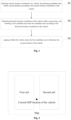
Fig. 1 is a flow diagram of a vehicle positioning method provided by an embodiment of the present invention; -
Fig. 2 is a schematic diagram of a vehicle coordinate location for vehicle positioning provided by an embodiment of the present invention; -
Fig. 3 is a schematic diagram of an included angle between a vehicle driving trajectory vector and a vector of entering a candidate area provided by an embodiment of the present invention; -
Fig. 4 is a schematic diagram of a vehicle positioning device provided by an embodiment of the present invention. - In order to further illustrate the technical means and effects adopted in the present invention to achieve the intended purpose of the invention, specific embodiments and effects of a vehicle positioning method and system proposed in accordance with the present invention are described in detail below, in conjunction with the drawings and preferred embodiments.
- As shown in
Fig. 1 , the present invention provides a vehicle positioning method. The following embodiments are described based on a GPS system. The method includes the following steps: - S1. Obtaining current location coordinates of a vehicle, and selecting candidate areas within a preset distance according to the current location coordinates of the vehicle; and the preset distance can be set according to the traffic conditions, the geographic environment and other information of the area where the vehicle is located.
- S2. Obtaining historical GPS coordinates of the vehicle within a preset time, and selecting a first candidate area from the candidate areas according to the historical GPS coordinates of the vehicle; and the preset time can be set according to specific traffic conditions, the geographic environment, the average driving speed of the vehicle in the candidate areas and other information.
- S3. Judging whether the vehicle enters the first candidate area to determine the current location of the vehicle. If the vehicle enters the first candidate area, the vehicle is currently in the first candidate area, if the vehicle does not enter the first candidate area, the vehicle is not in the first candidate area, the location of the vehicle is obtained again, the preset distance value and the preset time value are adjusted, and the steps S1-S3 are repeated to perform location judgment, until the current location of the vehicle is determined.
- It should be noted that, the GPS coordinates described in the embodiment of the present invention are not limited thereto and depend on the positioning system used. For example, if BDS is used for positioning, the location coordinates should be BDS coordinates.
- The problem of unclear location of the vehicle is descried in the following embodiments in specific scenarios:
As shown inFig. 2 , in the case of two adjacent cells, the two cells are respectively set as a first cell and a second cell, the current coordinate location submitted by the vehicle appears on an adjacent side of the two cells after being drawn on the map, and at this time, the POI information of the vehicle is difficult to judge. In this case, the location of the vehicle has the following two possibilities: - 1. Located in the first cell; and
- 2. Located in the second cell.
- For this kind of scenario, the historical trajectory of the vehicle is obtained via the characteristic that the vehicle periodically uploads the currently located GPS location during the driving process, so as to judge the accurate location of the vehicle.
- In this scenario, in the step S1, the first cell and the second cell are the candidate areas within the preset distance.
- Then, step S2 is executed: selecting the preset time, wherein the preset time can be selected as 1 hour in this scenario, obtaining the historical GPS coordinates of the vehicle within 1 hour, and selecting the first candidate area from the first cell and the second cell according to the historical GPS coordinates of the vehicle, which specifically includes the following steps:
- S201. Obtaining the GPS coordinates of all entrances of the first cell and the second cell;
- S202. Comparing the historical GPS coordinates of the vehicle with the GPS coordinates of all entrances of the first cell and the second cell in a reverse chronological manner; and
- S203. Selecting the cell corresponding to the entrance of the candidate area that the vehicle passes through most recently as the first candidate area according to the comparison result.
- Specifically, assuming that in the step S201, the first cell has two entrances, and the corresponding GPS coordinates are: (1, 1) and (1,2); the second cell has one entrance, and the corresponding GPS coordinates are (2, 1). It should be noted that the scenario is only used as a specific embodiment to illustrate the present invention, the number of the candidate areas is not limited to two, but can also be multiple, and similarly, the number of the entrances of the candidate areas is not unique, which is analyzed according to the specific scenario.
- By searching for the historical driving trajectory of the vehicle, it can be seen that the vehicle passes through (2, 1) half an hour ago, passes through (1, 1) one hour ago, and does not pass through the coordinates of the entrances of other cells thereafter. Then, it can be seen that the entrance point of the cell that the vehicle passes through most recently is (2, 1), and then, the second cell is selected as the first candidate area.
- There may also be a special situation in this scenario: if the distance between the entrances of the first cell and the second cell is very small, and the coordinate point of the entrance of the cell that the vehicle passes through most recently is just located between the entrance of the first cell and the entrance of the second cell, then the following judgement needs to be further performed:
calculating the distances between three coordinate points, that is, when the vehicle passes the space between the entrance of the first cell and the entrance of the second cell, a previous time point and a subsequent time point, with the entrance of the first cell and the entrance of the second cell, comparing the distances, and selecting the cell with the minimum distance as the first candidate area. - After the first candidate area is determined, operations corresponding to the step S3 are performed:
the judging whether the vehicle enters the second cell includes the following steps: - S301. Obtaining a vector in a direction entering the second cell at the entrance of the second cell to serve as a first vector;
- S302. Obtaining a driving vector of the vehicle at the entrance of the second cell to serve as a second vector; and
- S303. Calculating an included angle between the first vector and the second vector, and judging whether the vehicle enters the second cell according to the included angle, as shown in
Fig. 3 . - Preferably, the step S301 includes the following steps:
- S311. Selecting a point at the entrance of the second cell to serve as a starting point of the first vector, or directly using the coordinates (2, 1) of the entrance of the second cell as the starting point of the first vector; and
- S312. Selecting a point on a ray in the direction entering the second cell to serve as an end point of the first vector, so as to obtain the first vector.
- The step S302 includes the following steps:
- S321. Obtaining a coordinate point at which the vehicle passes through the entrance of the second cell most recently within the preset time to serve as the starting point of the second vector; and
- S222. Starting from the starting point of the second vector, selecting the next driving trajectory point in the historical trajectory of the vehicle to serve as the end point of the second vector, so as to obtain the second vector.
- Further, the calculating an included angle between the first vector and the second vector, and judging whether the vehicle enters the second cell according to the included angle includes the following steps:
- setting the first vector as (x1, y1), setting the second vector as (x2, y2), setting the included angle between the first vector and the second vector as θ, and calculating θ by the following formula:

- if 0° ≤ θ < 90°, judging that the vehicle enters the second cell, and that the current location of the vehicle is the second cell; and
- if 90° ≤ θ ≤ 180°, judging that the vehicle does not enter the second cell, and that the current location of the vehicle is not in the first cell or the second cell.
- As shown in
Fig. 3 , when the traveling trajectory of the vehicle is thevector 1, the included angle θ of which with the vector in the direction entering the second cell is less than 90°, and it can be judged that the vehicle enters the second cell; and the traveling trajectory of the vehicle is thevector 2, and the included angle θ of which with the vector in the direction entering the second cell is greater than 90°, it can be judged that the vehicle leaves the cell. - The location of the vehicle is obtained again, the preset distance value and the preset time value are adjusted, and the steps S1-S3 are repeated to perform location judgment, until the current location of the vehicle is determined.
- According to the method described in the embodiment of the present invention, accurate vehicle location information is obtained through the historical driving trajectory information and the current POI information of the vehicle to identify the specific location where the vehicle is located more accurately; in the case of adjacent POIs, compared with the manner in the prior art that the POI information of the vehicle is judged by directly using the current GPS data, the POI information to which the vehicle belongs can be judged more accurately, without being disturbed by multiple adjacent POIs and other information, the problem that the POI boundary is difficult to judge is solved, and the positioning accuracy is high; and in addition, the location of the vehicle is judged in the method by calculating the included angle between the vectors in the driving direction of the vehicle and the direction entering the first candidate area, the calculation amount is relatively small, and the result can be quickly calculated and inferred, the calculation mode is simple, convenient and feasible, and the efficiency is high.
- The embodiment of the present invention further provides a vehicle positioning device. As shown in
Fig. 4 , the device includes:
a firstarea selection module 1, configured to obtain current location coordinates of a vehicle, and select candidate areas within a preset distance according to the current location coordinates of the vehicle; and the preset distance can be set according to the traffic conditions, the geographic environment and other information of the area where the vehicle is located. - A second
area selection module 2, configured to obtain historical GPS coordinates of the vehicle within a preset time, and select a first candidate area from the candidate areas according to the historical GPS coordinates of the vehicle; and the preset time can be set according to specific traffic conditions, the geographic environment, the average driving speed of the vehicle in the candidate areas and other information. - A judging
module 3, configured to judge whether the vehicle enters the first candidate area to determine the current location of the vehicle. If the vehicle enters the first candidate area, the vehicle is currently in the first candidate area, if the vehicle does not enter the first candidate area, the vehicle is not in the first candidate area, the location of the vehicle is obtained again, the preset distance value and the preset time value are adjusted, and the steps S1-S3 are repeated to perform location judgment, until the current location of the vehicle is determined. - The problem of unclear location of the vehicle is descried in the following embodiments in specific scenarios:
As shown inFig. 2 , in the case of two adjacent cells, the two cells are respectively set as a first cell and a second cell, the current coordinate location submitted by the vehicle appears on an adjacent side of the two cells after being drawn on the map, and at this time, the POI information of the vehicle is difficult to judge. In this case, the location of the vehicle has the following two possibilities: - 1. Located in the first cell; and
- 2. Located in the second cell.
- For this kind of scenario, the historical trajectory of the vehicle is obtained via the characteristic that the vehicle periodically uploads the currently located GPS location during the driving process, so as to judge the accurate location of the vehicle.
- In this scenario, the first
area selection module 1 selects the first cell and the second cell as the candidate areas within the preset distance. - The second
area selection module 2 selects the preset time, wherein the preset time can be selected as 1 hour in this scenario, obtains the historical GPS coordinates of the vehicle within 1 hour, and selects the first candidate area from the first cell and the second cell according to the historical GPS coordinates of the vehicle. - The second
area selection module 2 includes: - a first coordinate obtaining unit, configured to obtain the GPS coordinates of all entrances of the first cell and the second cell;
- a coordinate comparison unit, configured to compare the historical GPS coordinates of the vehicle with the GPS coordinates of all entrances of the first cell and the second cell in a reverse chronological manner; and
- a first candidate area selection unit, configured to select the candidate area corresponding to the entrance of the candidate area that the vehicle passes through most recently as the first candidate area according to the comparison result.
- Specifically, assuming that the first cell has two entrances, and the corresponding GPS coordinates are: (1, 1) and (1,2); the second cell has one entrance, and the corresponding GPS coordinates are (2, 1). It should be noted that the scenario is only used as a specific embodiment to illustrate the present invention, the number of the candidate areas is not limited to two, but can also be multiple, and similarly, the number of the entrances of the candidate areas is not unique, which is analyzed according to the specific scenario.
- By searching for the historical driving trajectory of the vehicle, it can be seen that the vehicle passes through (2, 1) half an hour ago, passes through (1, 1) one hour ago, and does not pass through the coordinates of the entrances of other cells thereafter. Then, it can be seen that the entrance point of the cell that the vehicle passes through most recently is (2, 1), and then, the first candidate area selection unit selects the second cell as the first candidate area.
- There may also be a special situation in this scenario: if the distance between the entrances of the first cell and the second cell is very small, and the coordinate point of the entrance of the cell that the vehicle passes through most recently is just located between the entrance of the first cell and the entrance of the second cell, then the first candidate area selection unit needs to perform the following judgement: calculating the distances between three coordinate points, that is, when the vehicle passes the space between the entrance of the first cell and the entrance of the second cell, a previous time point and a subsequent time point, with the entrance of the first cell and the entrance of the second cell, comparing the distances, and selecting the cell with the minimum distance as the first candidate area.
- The judging
module 3 includes: - a first vector obtaining unit, configured to obtain a vector in a direction entering the second cell at the entrance of the second cell to serve as a first vector;
- a second vector obtaining unit, configured to obtain a driving vector of the vehicle at the entrance of the second cell to serve as a second vector; and
- a judging unit, configured to calculate an included angle between the first vector and the second vector, and judging whether the vehicle enters the second cell according to the included angle, as shown in
Fig. 3 . - Preferably, the first vector obtaining unit is further configured to:
- select a point at the entrance of the second cell to serve as a starting point of the first vector, or directly use the coordinates (2, 1) of the entrance of the second cell as the starting point of the first vector; and
- select a point on a ray in the direction entering the second cell to serve as an end point of the first vector, so as to obtain the first vector.
- The second vector obtaining unit is further configured to:
- obtain a coordinate point at which the vehicle passes through the entrance of the second cell most recently within the preset time to serve as the starting point of the second vector; and
- starting from the starting point of the second vector, select the next driving trajectory point in the historical trajectory of the vehicle to serve as the end point of the second vector, so as to obtain the second vector.
- The judging unit includes:
- a calculation sub-unit, configured to calculate the included angle θ between the first vector and the second vector,
- set the first vector as (x1, y1), set the second vector as (x2, y2), set the included angle between the first vector and the second vector as θ, and specifically calculate θ by the following formula:

- a judging sub-unit, configured to judge whether the vehicle enters the first candidate area according to the included angle, specifically:
- if 0° ≤ θ < 90°, judge that the vehicle enters the second cell, and that the current location of the vehicle is the second cell; and
- if 90° ≤ θ ≤ 180°, judge that the vehicle does not enter the second cell, and that the current location of the vehicle is not in the first cell or the second cell.
- As shown in
Fig. 3 , when the traveling trajectory of the vehicle is thevector 1, the included angle θ of which with the vector in the direction entering the second cell is less than 90°, and the judging sub-unit judges that the vehicle enters the second cell; and the traveling trajectory of the vehicle is thevector 2, and the included angle θ of which with the vector in the direction entering the second cell is greater than 90°, and the judging sub-unit judges that the vehicle leaves the cell. - The first
area selection module 1 obtains the location of the vehicle again, adjusts the preset distance value and the preset time value, and performs location judgment again by using the device, until the current location of the vehicle is determined. - According to the device described in the embodiment of the present invention, accurate vehicle location information is obtained through the historical driving trajectory information and the current POI information of the vehicle to identify the specific location where the vehicle is located more accurately; in the case of adjacent POIs, compared with the manner in the prior art that the POI information of the vehicle is judged by directly using the current GPS data, the POI information to which the vehicle belongs can be judged more accurately, without being disturbed by multiple adjacent POIs and other information, the problem that the POI boundary is difficult to judge is solved, and the positioning accuracy is high; and in addition, the location of the vehicle is judged in the method by calculating the included angle between the vectors in the driving direction of the vehicle and the direction entering the first candidate area, the calculation amount is relatively small, and the result can be quickly calculated and inferred, the calculation mode is simple, convenient and feasible, and the efficiency is high.
- The embodiment of the present invention further provides a controller, including a memory and a processor, wherein the memory stores a computer program, and the program is configured to implement the steps of the method when executed by the processor.
- The embodiment of the present invention further provides a computer-readable storage medium for storing a computer instruction, wherein the instruction implements the steps of the method when executed by a computer or a processor.
- The above descriptions are only the preferred embodiments of the present invention, and do not limit the present invention in any form. Although the present invention has been disclosed in the preferred embodiments as above, the preferred embodiments are not used for limiting the present invention, anyone skilled familiar with this art can make some changes or modifications by using the technical contents disclosed above to serve as equivalent embodiments of equivalent changes, without departing from the scope of the technical solutions of the present invention as defined in the appended claims, and any simple modifications, equivalent changes and modifications made to the above embodiments according to the technical essence of the present invention as defined in the appended claims, without departing from the contents of the technical solutions of the present invention, still fall within the scope of the technical solutions of the present invention as defined in the appended claims.
Claims (11)
- A vehicle positioning method, comprising the following steps:obtaining current location coordinates of a vehicle, and selecting candidate areas within a preset distance according to the current location coordinates of the vehicle (S1);obtaining historical location coordinates of the vehicle within a preset time, and selecting a first candidate area from the candidate areas according to the historical location coordinates of the vehicle (S2); andjudging whether the vehicle enters the first candidate area to determine the current location of the vehicle (S3),characterized in that,judging whether the vehicle enters the first candidate area (S3) comprises:obtaining a vector in a direction entering the first candidate area at an entrance of the first candidate area to serve as a first vector;obtaining a driving vector of the vehicle at the entrance of the first candidate area to serve as a second vector, comprising
obtaining a coordinate point at which the vehicle passes through the entrance of the first candidate area within the preset time to serve as the starting point of the second vector; and starting from the starting point of the second vector, selecting the next driving trajectory point in the historical trajectory of the vehicle to serve as the end point of the second vector, so as to obtain the second vector; andcalculating an included angle between the first vector and the second vector, and judging whether the vehicle enters the first candidate area according to the included angle. - The vehicle positioning method according to claim 1, wherein the selecting a first candidate area from the candidate areas according to the historical location coordinates of the vehicle (S2) comprises the following steps:obtaining the location coordinates of the entrances of the candidate areas;comparing the historical location coordinates of the vehicle with the location coordinates of the entrances of the candidate areas in a reverse chronological manner; andselecting the candidate area corresponding to the entrance of the candidate area that the vehicle passes through most recently as the first candidate area according to the comparison result.
- The vehicle positioning method according to claim 2, wherein:
if there are more than two entrances of the candidate areas that the vehicle pass through most recently, the following step is performed to select the first candidate area:
calculating the distances between three coordinate points, that is, when the vehicle passes the entrance of the candidate area, a previous time point and a subsequent time point, and the entrance of each candidate area that the vehicle passes through most recently, comparing the distances, and selecting the candidate area with the minimum distance as the first candidate area. - The vehicle positioning method according to claim 1, wherein:
the obtaining a vector in a direction entering the first candidate area at the entrance of the first candidate area to serve as a first vector comprises the following steps:selecting a point at the entrance of the first candidate area to serve as a starting point of the first vector; andselecting a point on a ray in the direction entering the first candidate area to serve as an end point of the first vector, so as to obtain the first vector. - The vehicle positioning method according to claim 1, wherein:
the calculating an included angle between the first vector and the second vector, and judging whether the vehicle enters the first candidate area according to the included angle comprises the following steps:setting the first vector as (x1, y1), setting the second vector as (x2, y2), setting the included angle between the first vector and the second vector as θ, and calculating θ by the following formula: if 0° ≤ θ < 90°, judging that the vehicle enters the first candidate area, and that the current location of the vehicle is the first candidate area; andif 90° ≤ θ ≤ 180°, judging that the vehicle does not enter the first candidate area, and that the current location of the vehicle is not in the candidate area within the selected preset distance.
 - A vehicle positioning device, comprising:a first area selection module (1), configured to obtain current location coordinates of a vehicle, and select candidate areas within a preset distance according to the current location coordinates of the vehicle (S1);a second area selection module (2), configured to obtain historical location coordinates of the vehicle within a preset time, and select a first candidate area from the candidate areas according to the historical location coordinates of the vehicle (S2); anda judging module (3), configured to judge whether the vehicle enters the first candidate area to determine the current location of the vehicle (S3),characterized in that,the judging module (3) comprises:a first vector obtaining unit, configured to obtain a vector in a direction entering the first candidate area at an entrance of the first candidate area to serve as a first vector;a second vector obtaining unit, configured to obtain a driving vector of the vehicle at the entrance of the first candidate area to serve as a second vector, whereinthe second vector obtaining unit is further configured to:
obtain a coordinate point at which the vehicle passes through the entrance of the first candidate area within the preset time to serve as the starting point of the second vector; and starting from the starting point of the second vector, select the next driving trajectory point in the historical trajectory of the vehicle to serve as the end point of the second vector, so as to obtain the second vector; and
a judging unit, configured to calculate an included angle between the first vector and the second vector, and judge whether the vehicle enters the first candidate area according to the included angle. - The vehicle positioning device according to claim 6, wherein:
the second area selection module (2) comprises:a first coordinate obtaining unit, configured to obtain the location coordinates of the entrances of the candidate areas;a coordinate comparison unit, configured to compare the historical location coordinates of the vehicle with the location coordinates of the entrances of the candidate areas in a reverse chronological manner; anda first candidate area selection unit, configured to select the candidate area corresponding to the entrance of the candidate area that the vehicle passes through most recently as the first candidate area according to the comparison result. - The vehicle positioning device according to claim 7, wherein if there are more than two entrances of the candidate areas that the vehicle pass through most recently, the first candidate area selection unit is further configured to:
calculate the distances between three coordinate points, that is, when the vehicle passes through the entrance of the candidate area, a previous time point and a subsequent time point, and the entrance of each candidate area that the vehicle passes through most recently, compare the distances, and select the candidate area with the minimum distance as the first candidate area. - The vehicle positioning device according to claim 6, wherein the first vector obtaining unit is further configured to:select a point at the entrance of the first candidate area to serve as a starting point of the first vector; andselect a point on a ray in the direction entering the first candidate area to serve as an end point of the first vector, so as to obtain the first vector.
- The vehicle positioning device according to claim 6, wherein the judging unit comprises:a calculation sub-unit, configured to calculate the included angle θ between the first vector and the second vector,set the first vector as (x1, y1), set the second vector as (x2, y2), set the included angle between the first vector and the second vector as θ, and specifically calculate θ by the following formula:
 a judging sub-unit, configured to judge whether the vehicle enters the first candidate area according to the included angle, specifically:if 0° ≤ θ < 90°, judge that the vehicle enters the first candidate area, and that the current location of the vehicle is the first candidate area; andif 90° ≤ θ ≤ 180°, judge that the vehicle does not enter the first candidate area, and that the current location of the vehicle is not in the candidate area within the selected preset distance.
 - A controller, comprising a memory and a processor, wherein the memory stores a computer program, and the program is configured to implement the steps of the method according to any of claims 1-5 when executed by the processor.
Applications Claiming Priority (2)
| Application Number | Priority Date | Filing Date | Title |
|---|---|---|---|
| CN201710985393.XA CN108398701B (en) | 2017-10-20 | 2017-10-20 | Vehicle positioning method and device |
| PCT/CN2018/100031 WO2019076119A1 (en) | 2017-10-20 | 2018-08-10 | Vehicle positioning method and device |
Publications (3)
| Publication Number | Publication Date |
|---|---|
| EP3699642A1 EP3699642A1 (en) | 2020-08-26 |
| EP3699642A4 EP3699642A4 (en) | 2021-07-21 |
| EP3699642B1 true EP3699642B1 (en) | 2025-03-26 |
Family
ID=63094722
Family Applications (1)
| Application Number | Title | Priority Date | Filing Date |
|---|---|---|---|
| EP18868537.4A Active EP3699642B1 (en) | 2017-10-20 | 2018-08-10 | Vehicle positioning method and apparatus |
Country Status (3)
| Country | Link |
|---|---|
| EP (1) | EP3699642B1 (en) |
| CN (1) | CN108398701B (en) |
| WO (1) | WO2019076119A1 (en) |
Families Citing this family (6)
| Publication number | Priority date | Publication date | Assignee | Title |
|---|---|---|---|---|
| CN109413206A (en) * | 2018-12-10 | 2019-03-01 | 广州道安信息科技有限公司 | Transport device driving trace judgment method, computer installation and computer readable storage medium |
| CN111508223B (en) * | 2019-01-30 | 2021-11-26 | 杭州海康威视数字技术股份有限公司 | Vehicle passage detection method and vehicle passage detection device |
| CN110243368A (en) * | 2019-04-29 | 2019-09-17 | 丰疆智能科技研究院(常州)有限公司 | The driving trace of intelligent agricultural machinery establishes system and its application |
| CN112147572B (en) * | 2019-06-28 | 2023-11-14 | 比亚迪股份有限公司 | Positioning method and positioning device for rail vehicles |
| CN111221015B (en) * | 2020-01-13 | 2025-07-18 | 腾讯科技(深圳)有限公司 | Equipment positioning method, device and computer readable storage medium |
| CN113820658B (en) * | 2021-08-18 | 2024-09-20 | 上海闻泰电子科技有限公司 | Wireless positioning method, device, electronic device and storage medium |
Family Cites Families (11)
| Publication number | Priority date | Publication date | Assignee | Title |
|---|---|---|---|---|
| WO2005024688A1 (en) * | 2003-09-05 | 2005-03-17 | Matsushita Electric Industrial Co., Ltd. | Visiting place identification device and visiting place identification method |
| JP2005250853A (en) * | 2004-03-04 | 2005-09-15 | Ntt Docomo Inc | MOBILE BODY MONITORING SYSTEM AND MOBILE BODY MONITORING METHOD |
| CN100387098C (en) * | 2005-10-18 | 2008-05-07 | 华为技术有限公司 | A location-based information providing method and system |
| JP4254889B2 (en) * | 2007-09-06 | 2009-04-15 | トヨタ自動車株式会社 | Vehicle position calculation device |
| US20100141432A1 (en) * | 2008-10-20 | 2010-06-10 | Binay Sugla | Correcting and/or improving location information using object location history, topology, and/or other information |
| CN101887127B (en) * | 2010-03-19 | 2014-09-03 | 深圳市安巨科技有限公司 | Vehicle monitoring processing method and device and GPS (Global Positioning System) server and vehicle monitoring system |
| KR101405434B1 (en) * | 2012-11-23 | 2014-06-11 | 현대엠엔소프트 주식회사 | Device and method for generating guiding information about crossroad |
| RU2608885C2 (en) * | 2014-06-30 | 2017-01-25 | Общество С Ограниченной Ответственностью "Яндекс" | Method for determining the curve point nearest to the position on the map |
| CN105791496B (en) * | 2014-12-24 | 2019-07-05 | 高德软件有限公司 | A kind of mobile terminal state detection method and device |
| JP6633460B2 (en) * | 2015-09-04 | 2020-01-22 | パナソニック インテレクチュアル プロパティ コーポレーション オブ アメリカPanasonic Intellectual Property Corporation of America | Notification method, notification device and terminal |
| CN106982416B (en) * | 2017-03-21 | 2019-10-18 | 深圳广联赛讯有限公司 | The method and apparatus for determining vehicle ownership place |
-
2017
- 2017-10-20 CN CN201710985393.XA patent/CN108398701B/en active Active
-
2018
- 2018-08-10 EP EP18868537.4A patent/EP3699642B1/en active Active
- 2018-08-10 WO PCT/CN2018/100031 patent/WO2019076119A1/en not_active Ceased
Also Published As
| Publication number | Publication date |
|---|---|
| EP3699642A4 (en) | 2021-07-21 |
| WO2019076119A1 (en) | 2019-04-25 |
| EP3699642A1 (en) | 2020-08-26 |
| CN108398701B (en) | 2020-07-03 |
| CN108398701A (en) | 2018-08-14 |
Similar Documents
| Publication | Publication Date | Title |
|---|---|---|
| EP3699642A1 (en) | Vehicle positioning method and apparatus | |
| CN111176269B (en) | Course adjusting method and device of vehicle, vehicle and storage medium | |
| US11168989B2 (en) | Supervised point map matcher | |
| EP3859273B1 (en) | Method for constructing driving coordinate system, and application thereof | |
| CN113538919A (en) | Lane departure recognition method, apparatus, device, and storage medium | |
| EP3644016B1 (en) | Localization using dynamic landmarks | |
| CN107883950B (en) | Parking lot navigation method, device and system | |
| EP2950047B1 (en) | Pedestrian navigation processing method, terminal device and system | |
| US20150262481A1 (en) | System and method to determine occurrence of platoon | |
| CN111746525B (en) | Parking path planning method, device, equipment and storage medium | |
| CN109444932A (en) | A kind of vehicle positioning method, device, electronic equipment and storage medium | |
| CN108828645A (en) | A kind of navigation locating method, system, equipment and computer readable storage medium | |
| WO2020216342A1 (en) | Position and attitude data processing method and system | |
| CN104200042A (en) | Positioning-data trajectory tracking method | |
| CN107784012A (en) | A kind of update method and device of numerical map point of interest | |
| US11805390B2 (en) | Method, apparatus, and computer program product for determining sensor orientation | |
| CN113252025A (en) | Positioning detection method and device, electronic equipment and storage medium | |
| CN106525043A (en) | Intelligent route planning method | |
| CN112214014A (en) | Agricultural machinery automatic driving control method and system | |
| CN115042787A (en) | A method and device for determining a tracking trajectory without lane lines | |
| CN114705180B (en) | Data correction method, device and equipment for high-precision map and storage medium | |
| CN116674590A (en) | Path generation method, device and electronic equipment based on automatic driving | |
| CN111207759A (en) | Method and device for displaying vehicle position | |
| JP2019174191A (en) | Data structure, information transmitting device, control method, program, and storage medium | |
| CN107228675A (en) | A kind of determination method of road residing for terminal, apparatus and system |
Legal Events
| Date | Code | Title | Description |
|---|---|---|---|
| STAA | Information on the status of an ep patent application or granted ep patent |
Free format text: STATUS: THE INTERNATIONAL PUBLICATION HAS BEEN MADE |
|
| PUAI | Public reference made under article 153(3) epc to a published international application that has entered the european phase |
Free format text: ORIGINAL CODE: 0009012 |
|
| STAA | Information on the status of an ep patent application or granted ep patent |
Free format text: STATUS: REQUEST FOR EXAMINATION WAS MADE |
|
| 17P | Request for examination filed |
Effective date: 20200519 |
|
| AK | Designated contracting states |
Kind code of ref document: A1 Designated state(s): AL AT BE BG CH CY CZ DE DK EE ES FI FR GB GR HR HU IE IS IT LI LT LU LV MC MK MT NL NO PL PT RO RS SE SI SK SM TR |
|
| AX | Request for extension of the european patent |
Extension state: BA ME |
|
| RAP1 | Party data changed (applicant data changed or rights of an application transferred) |
Owner name: NIO (ANHUI) HOLDING CO., LTD. |
|
| RIN1 | Information on inventor provided before grant (corrected) |
Inventor name: ZHANG, XIAODONG |
|
| DAV | Request for validation of the european patent (deleted) | ||
| DAX | Request for extension of the european patent (deleted) | ||
| REG | Reference to a national code |
Ref country code: DE Ref legal event code: R079 Free format text: PREVIOUS MAIN CLASS: G01S0019420000 Ipc: G01S0005020000 Ref document number: 602018080566 Country of ref document: DE |
|
| A4 | Supplementary search report drawn up and despatched |
Effective date: 20210618 |
|
| RIC1 | Information provided on ipc code assigned before grant |
Ipc: G01S 5/02 20100101AFI20210614BHEP Ipc: G01S 19/40 20100101ALI20210614BHEP |
|
| STAA | Information on the status of an ep patent application or granted ep patent |
Free format text: STATUS: EXAMINATION IS IN PROGRESS |
|
| 17Q | First examination report despatched |
Effective date: 20240820 |
|
| GRAP | Despatch of communication of intention to grant a patent |
Free format text: ORIGINAL CODE: EPIDOSNIGR1 |
|
| STAA | Information on the status of an ep patent application or granted ep patent |
Free format text: STATUS: GRANT OF PATENT IS INTENDED |
|
| INTG | Intention to grant announced |
Effective date: 20241212 |
|
| GRAS | Grant fee paid |
Free format text: ORIGINAL CODE: EPIDOSNIGR3 |
|
| GRAA | (expected) grant |
Free format text: ORIGINAL CODE: 0009210 |
|
| STAA | Information on the status of an ep patent application or granted ep patent |
Free format text: STATUS: THE PATENT HAS BEEN GRANTED |
|
| AK | Designated contracting states |
Kind code of ref document: B1 Designated state(s): AL AT BE BG CH CY CZ DE DK EE ES FI FR GB GR HR HU IE IS IT LI LT LU LV MC MK MT NL NO PL PT RO RS SE SI SK SM TR |
|
| REG | Reference to a national code |
Ref country code: GB Ref legal event code: FG4D |
|
| REG | Reference to a national code |
Ref country code: CH Ref legal event code: EP |
|
| REG | Reference to a national code |
Ref country code: DE Ref legal event code: R096 Ref document number: 602018080566 Country of ref document: DE |
|
| REG | Reference to a national code |
Ref country code: IE Ref legal event code: FG4D |
|
| PG25 | Lapsed in a contracting state [announced via postgrant information from national office to epo] |
Ref country code: RS Free format text: LAPSE BECAUSE OF FAILURE TO SUBMIT A TRANSLATION OF THE DESCRIPTION OR TO PAY THE FEE WITHIN THE PRESCRIBED TIME-LIMIT Effective date: 20250626 |
|
| PG25 | Lapsed in a contracting state [announced via postgrant information from national office to epo] |
Ref country code: FI Free format text: LAPSE BECAUSE OF FAILURE TO SUBMIT A TRANSLATION OF THE DESCRIPTION OR TO PAY THE FEE WITHIN THE PRESCRIBED TIME-LIMIT Effective date: 20250326 |
|
| REG | Reference to a national code |
Ref country code: LT Ref legal event code: MG9D |
|
| PG25 | Lapsed in a contracting state [announced via postgrant information from national office to epo] |
Ref country code: NO Free format text: LAPSE BECAUSE OF FAILURE TO SUBMIT A TRANSLATION OF THE DESCRIPTION OR TO PAY THE FEE WITHIN THE PRESCRIBED TIME-LIMIT Effective date: 20250626 |
|
| PG25 | Lapsed in a contracting state [announced via postgrant information from national office to epo] |
Ref country code: HR Free format text: LAPSE BECAUSE OF FAILURE TO SUBMIT A TRANSLATION OF THE DESCRIPTION OR TO PAY THE FEE WITHIN THE PRESCRIBED TIME-LIMIT Effective date: 20250326 |
|
| PG25 | Lapsed in a contracting state [announced via postgrant information from national office to epo] |
Ref country code: LV Free format text: LAPSE BECAUSE OF FAILURE TO SUBMIT A TRANSLATION OF THE DESCRIPTION OR TO PAY THE FEE WITHIN THE PRESCRIBED TIME-LIMIT Effective date: 20250326 |
|
| PG25 | Lapsed in a contracting state [announced via postgrant information from national office to epo] |
Ref country code: GR Free format text: LAPSE BECAUSE OF FAILURE TO SUBMIT A TRANSLATION OF THE DESCRIPTION OR TO PAY THE FEE WITHIN THE PRESCRIBED TIME-LIMIT Effective date: 20250627 Ref country code: BG Free format text: LAPSE BECAUSE OF FAILURE TO SUBMIT A TRANSLATION OF THE DESCRIPTION OR TO PAY THE FEE WITHIN THE PRESCRIBED TIME-LIMIT Effective date: 20250326 |
|
| REG | Reference to a national code |
Ref country code: NL Ref legal event code: MP Effective date: 20250326 |
|
| PG25 | Lapsed in a contracting state [announced via postgrant information from national office to epo] |
Ref country code: NL Free format text: LAPSE BECAUSE OF FAILURE TO SUBMIT A TRANSLATION OF THE DESCRIPTION OR TO PAY THE FEE WITHIN THE PRESCRIBED TIME-LIMIT Effective date: 20250326 |
|
| PG25 | Lapsed in a contracting state [announced via postgrant information from national office to epo] |
Ref country code: SE Free format text: LAPSE BECAUSE OF FAILURE TO SUBMIT A TRANSLATION OF THE DESCRIPTION OR TO PAY THE FEE WITHIN THE PRESCRIBED TIME-LIMIT Effective date: 20250326 |
|
| REG | Reference to a national code |
Ref country code: AT Ref legal event code: MK05 Ref document number: 1779448 Country of ref document: AT Kind code of ref document: T Effective date: 20250326 |
|
| PG25 | Lapsed in a contracting state [announced via postgrant information from national office to epo] |
Ref country code: SM Free format text: LAPSE BECAUSE OF FAILURE TO SUBMIT A TRANSLATION OF THE DESCRIPTION OR TO PAY THE FEE WITHIN THE PRESCRIBED TIME-LIMIT Effective date: 20250326 |
|
| PG25 | Lapsed in a contracting state [announced via postgrant information from national office to epo] |
Ref country code: ES Free format text: LAPSE BECAUSE OF FAILURE TO SUBMIT A TRANSLATION OF THE DESCRIPTION OR TO PAY THE FEE WITHIN THE PRESCRIBED TIME-LIMIT Effective date: 20250326 Ref country code: PT Free format text: LAPSE BECAUSE OF FAILURE TO SUBMIT A TRANSLATION OF THE DESCRIPTION OR TO PAY THE FEE WITHIN THE PRESCRIBED TIME-LIMIT Effective date: 20250728 |
|
| PGFP | Annual fee paid to national office [announced via postgrant information from national office to epo] |
Ref country code: DE Payment date: 20250820 Year of fee payment: 8 |
|
| PG25 | Lapsed in a contracting state [announced via postgrant information from national office to epo] |
Ref country code: IT Free format text: LAPSE BECAUSE OF FAILURE TO SUBMIT A TRANSLATION OF THE DESCRIPTION OR TO PAY THE FEE WITHIN THE PRESCRIBED TIME-LIMIT Effective date: 20250326 Ref country code: PL Free format text: LAPSE BECAUSE OF FAILURE TO SUBMIT A TRANSLATION OF THE DESCRIPTION OR TO PAY THE FEE WITHIN THE PRESCRIBED TIME-LIMIT Effective date: 20250326 |
|
| PGFP | Annual fee paid to national office [announced via postgrant information from national office to epo] |
Ref country code: GB Payment date: 20250820 Year of fee payment: 8 |
|
| PG25 | Lapsed in a contracting state [announced via postgrant information from national office to epo] |
Ref country code: AT Free format text: LAPSE BECAUSE OF FAILURE TO SUBMIT A TRANSLATION OF THE DESCRIPTION OR TO PAY THE FEE WITHIN THE PRESCRIBED TIME-LIMIT Effective date: 20250326 |
|
| PGFP | Annual fee paid to national office [announced via postgrant information from national office to epo] |
Ref country code: FR Payment date: 20250828 Year of fee payment: 8 |
|
| PG25 | Lapsed in a contracting state [announced via postgrant information from national office to epo] |
Ref country code: EE Free format text: LAPSE BECAUSE OF FAILURE TO SUBMIT A TRANSLATION OF THE DESCRIPTION OR TO PAY THE FEE WITHIN THE PRESCRIBED TIME-LIMIT Effective date: 20250326 |
|
| PG25 | Lapsed in a contracting state [announced via postgrant information from national office to epo] |
Ref country code: RO Free format text: LAPSE BECAUSE OF FAILURE TO SUBMIT A TRANSLATION OF THE DESCRIPTION OR TO PAY THE FEE WITHIN THE PRESCRIBED TIME-LIMIT Effective date: 20250326 |
|
| PG25 | Lapsed in a contracting state [announced via postgrant information from national office to epo] |
Ref country code: SK Free format text: LAPSE BECAUSE OF FAILURE TO SUBMIT A TRANSLATION OF THE DESCRIPTION OR TO PAY THE FEE WITHIN THE PRESCRIBED TIME-LIMIT Effective date: 20250326 |
|
| PG25 | Lapsed in a contracting state [announced via postgrant information from national office to epo] |
Ref country code: IS Free format text: LAPSE BECAUSE OF FAILURE TO SUBMIT A TRANSLATION OF THE DESCRIPTION OR TO PAY THE FEE WITHIN THE PRESCRIBED TIME-LIMIT Effective date: 20250726 |
|
| REG | Reference to a national code |
Ref country code: DE Ref legal event code: R097 Ref document number: 602018080566 Country of ref document: DE |
|
| PG25 | Lapsed in a contracting state [announced via postgrant information from national office to epo] |
Ref country code: DK Free format text: LAPSE BECAUSE OF FAILURE TO SUBMIT A TRANSLATION OF THE DESCRIPTION OR TO PAY THE FEE WITHIN THE PRESCRIBED TIME-LIMIT Effective date: 20250326 |
|
| PG25 | Lapsed in a contracting state [announced via postgrant information from national office to epo] |
Ref country code: CZ Free format text: LAPSE BECAUSE OF FAILURE TO SUBMIT A TRANSLATION OF THE DESCRIPTION OR TO PAY THE FEE WITHIN THE PRESCRIBED TIME-LIMIT Effective date: 20250326 |
|
| PLBE | No opposition filed within time limit |
Free format text: ORIGINAL CODE: 0009261 |
|
| STAA | Information on the status of an ep patent application or granted ep patent |
Free format text: STATUS: NO OPPOSITION FILED WITHIN TIME LIMIT |
|
| REG | Reference to a national code |
Ref country code: CH Ref legal event code: L10 Free format text: ST27 STATUS EVENT CODE: U-0-0-L10-L00 (AS PROVIDED BY THE NATIONAL OFFICE) Effective date: 20260211 |
|
| 26N | No opposition filed |
Effective date: 20260105 |
|
| REG | Reference to a national code |
Ref country code: CH Ref legal event code: H13 Free format text: ST27 STATUS EVENT CODE: U-0-0-H10-H13 (AS PROVIDED BY THE NATIONAL OFFICE) Effective date: 20260324 |
|
| PG25 | Lapsed in a contracting state [announced via postgrant information from national office to epo] |
Ref country code: MC Free format text: LAPSE BECAUSE OF FAILURE TO SUBMIT A TRANSLATION OF THE DESCRIPTION OR TO PAY THE FEE WITHIN THE PRESCRIBED TIME-LIMIT Effective date: 20250326 |
|
| PG25 | Lapsed in a contracting state [announced via postgrant information from national office to epo] |
Ref country code: LU Free format text: LAPSE BECAUSE OF NON-PAYMENT OF DUE FEES Effective date: 20250810 |
|
| PG25 | Lapsed in a contracting state [announced via postgrant information from national office to epo] |
Ref country code: CH Free format text: LAPSE BECAUSE OF NON-PAYMENT OF DUE FEES Effective date: 20250831 |
|
| REG | Reference to a national code |
Ref country code: BE Ref legal event code: MM Effective date: 20250831 |
|
| PG25 | Lapsed in a contracting state [announced via postgrant information from national office to epo] |
Ref country code: LT Free format text: LAPSE BECAUSE OF FAILURE TO SUBMIT A TRANSLATION OF THE DESCRIPTION OR TO PAY THE FEE WITHIN THE PRESCRIBED TIME-LIMIT Effective date: 20250326 |
|
| PG25 | Lapsed in a contracting state [announced via postgrant information from national office to epo] |
Ref country code: IE Free format text: LAPSE BECAUSE OF NON-PAYMENT OF DUE FEES Effective date: 20250810 Ref country code: BE Free format text: LAPSE BECAUSE OF NON-PAYMENT OF DUE FEES Effective date: 20250831 |