EP3699635A1 - Sensor control device - Google Patents
Sensor control device Download PDFInfo
- Publication number
- EP3699635A1 EP3699635A1 EP20150680.5A EP20150680A EP3699635A1 EP 3699635 A1 EP3699635 A1 EP 3699635A1 EP 20150680 A EP20150680 A EP 20150680A EP 3699635 A1 EP3699635 A1 EP 3699635A1
- Authority
- EP
- European Patent Office
- Prior art keywords
- band
- data
- signal
- control unit
- driving signal
- Prior art date
- Legal status (The legal status is an assumption and is not a legal conclusion. Google has not performed a legal analysis and makes no representation as to the accuracy of the status listed.)
- Ceased
Links
- 230000006854 communication Effects 0.000 claims abstract description 23
- 230000007274 generation of a signal involved in cell-cell signaling Effects 0.000 claims abstract description 20
- 230000007175 bidirectional communication Effects 0.000 claims abstract description 6
- 230000005540 biological transmission Effects 0.000 description 23
- 239000013585 weight reducing agent Substances 0.000 description 6
- 238000000034 method Methods 0.000 description 5
- 230000005236 sound signal Effects 0.000 description 4
- 238000010586 diagram Methods 0.000 description 2
- 238000009877 rendering Methods 0.000 description 2
- 230000001133 acceleration Effects 0.000 description 1
- 230000000903 blocking effect Effects 0.000 description 1
- 238000001514 detection method Methods 0.000 description 1
- 239000000446 fuel Substances 0.000 description 1
- 230000010354 integration Effects 0.000 description 1
- 230000011664 signaling Effects 0.000 description 1
- 238000011144 upstream manufacturing Methods 0.000 description 1
Images

Classifications
-
- G—PHYSICS
- G01—MEASURING; TESTING
- G01S—RADIO DIRECTION-FINDING; RADIO NAVIGATION; DETERMINING DISTANCE OR VELOCITY BY USE OF RADIO WAVES; LOCATING OR PRESENCE-DETECTING BY USE OF THE REFLECTION OR RERADIATION OF RADIO WAVES; ANALOGOUS ARRANGEMENTS USING OTHER WAVES
- G01S15/00—Systems using the reflection or reradiation of acoustic waves, e.g. sonar systems
- G01S15/87—Combinations of sonar systems
- G01S15/876—Combination of several spaced transmitters or receivers of known location for determining the position of a transponder or a reflector
-
- G—PHYSICS
- G01—MEASURING; TESTING
- G01S—RADIO DIRECTION-FINDING; RADIO NAVIGATION; DETERMINING DISTANCE OR VELOCITY BY USE OF RADIO WAVES; LOCATING OR PRESENCE-DETECTING BY USE OF THE REFLECTION OR RERADIATION OF RADIO WAVES; ANALOGOUS ARRANGEMENTS USING OTHER WAVES
- G01S15/00—Systems using the reflection or reradiation of acoustic waves, e.g. sonar systems
- G01S15/87—Combinations of sonar systems
-
- B—PERFORMING OPERATIONS; TRANSPORTING
- B60—VEHICLES IN GENERAL
- B60W—CONJOINT CONTROL OF VEHICLE SUB-UNITS OF DIFFERENT TYPE OR DIFFERENT FUNCTION; CONTROL SYSTEMS SPECIALLY ADAPTED FOR HYBRID VEHICLES; ROAD VEHICLE DRIVE CONTROL SYSTEMS FOR PURPOSES NOT RELATED TO THE CONTROL OF A PARTICULAR SUB-UNIT
- B60W50/00—Details of control systems for road vehicle drive control not related to the control of a particular sub-unit, e.g. process diagnostic or vehicle driver interfaces
-
- B—PERFORMING OPERATIONS; TRANSPORTING
- B60—VEHICLES IN GENERAL
- B60R—VEHICLES, VEHICLE FITTINGS, OR VEHICLE PARTS, NOT OTHERWISE PROVIDED FOR
- B60R16/00—Electric or fluid circuits specially adapted for vehicles and not otherwise provided for; Arrangement of elements of electric or fluid circuits specially adapted for vehicles and not otherwise provided for
- B60R16/02—Electric or fluid circuits specially adapted for vehicles and not otherwise provided for; Arrangement of elements of electric or fluid circuits specially adapted for vehicles and not otherwise provided for electric constitutive elements
- B60R16/023—Electric or fluid circuits specially adapted for vehicles and not otherwise provided for; Arrangement of elements of electric or fluid circuits specially adapted for vehicles and not otherwise provided for electric constitutive elements for transmission of signals between vehicle parts or subsystems
- B60R16/0231—Circuits relating to the driving or the functioning of the vehicle
-
- G—PHYSICS
- G01—MEASURING; TESTING
- G01S—RADIO DIRECTION-FINDING; RADIO NAVIGATION; DETERMINING DISTANCE OR VELOCITY BY USE OF RADIO WAVES; LOCATING OR PRESENCE-DETECTING BY USE OF THE REFLECTION OR RERADIATION OF RADIO WAVES; ANALOGOUS ARRANGEMENTS USING OTHER WAVES
- G01S15/00—Systems using the reflection or reradiation of acoustic waves, e.g. sonar systems
- G01S15/02—Systems using the reflection or reradiation of acoustic waves, e.g. sonar systems using reflection of acoustic waves
- G01S15/06—Systems determining the position data of a target
-
- G—PHYSICS
- G01—MEASURING; TESTING
- G01S—RADIO DIRECTION-FINDING; RADIO NAVIGATION; DETERMINING DISTANCE OR VELOCITY BY USE OF RADIO WAVES; LOCATING OR PRESENCE-DETECTING BY USE OF THE REFLECTION OR RERADIATION OF RADIO WAVES; ANALOGOUS ARRANGEMENTS USING OTHER WAVES
- G01S15/00—Systems using the reflection or reradiation of acoustic waves, e.g. sonar systems
- G01S15/02—Systems using the reflection or reradiation of acoustic waves, e.g. sonar systems using reflection of acoustic waves
- G01S15/06—Systems determining the position data of a target
- G01S15/08—Systems for measuring distance only
- G01S15/10—Systems for measuring distance only using transmission of interrupted, pulse-modulated waves
-
- G—PHYSICS
- G01—MEASURING; TESTING
- G01S—RADIO DIRECTION-FINDING; RADIO NAVIGATION; DETERMINING DISTANCE OR VELOCITY BY USE OF RADIO WAVES; LOCATING OR PRESENCE-DETECTING BY USE OF THE REFLECTION OR RERADIATION OF RADIO WAVES; ANALOGOUS ARRANGEMENTS USING OTHER WAVES
- G01S15/00—Systems using the reflection or reradiation of acoustic waves, e.g. sonar systems
- G01S15/66—Sonar tracking systems
-
- G—PHYSICS
- G01—MEASURING; TESTING
- G01S—RADIO DIRECTION-FINDING; RADIO NAVIGATION; DETERMINING DISTANCE OR VELOCITY BY USE OF RADIO WAVES; LOCATING OR PRESENCE-DETECTING BY USE OF THE REFLECTION OR RERADIATION OF RADIO WAVES; ANALOGOUS ARRANGEMENTS USING OTHER WAVES
- G01S15/00—Systems using the reflection or reradiation of acoustic waves, e.g. sonar systems
- G01S15/88—Sonar systems specially adapted for specific applications
- G01S15/93—Sonar systems specially adapted for specific applications for anti-collision purposes
- G01S15/931—Sonar systems specially adapted for specific applications for anti-collision purposes of land vehicles
-
- G—PHYSICS
- G01—MEASURING; TESTING
- G01S—RADIO DIRECTION-FINDING; RADIO NAVIGATION; DETERMINING DISTANCE OR VELOCITY BY USE OF RADIO WAVES; LOCATING OR PRESENCE-DETECTING BY USE OF THE REFLECTION OR RERADIATION OF RADIO WAVES; ANALOGOUS ARRANGEMENTS USING OTHER WAVES
- G01S7/00—Details of systems according to groups G01S13/00, G01S15/00, G01S17/00
- G01S7/003—Transmission of data between radar, sonar or lidar systems and remote stations
-
- G—PHYSICS
- G01—MEASURING; TESTING
- G01V—GEOPHYSICS; GRAVITATIONAL MEASUREMENTS; DETECTING MASSES OR OBJECTS; TAGS
- G01V1/00—Seismology; Seismic or acoustic prospecting or detecting
- G01V1/001—Acoustic presence detection
-
- G—PHYSICS
- G01—MEASURING; TESTING
- G01S—RADIO DIRECTION-FINDING; RADIO NAVIGATION; DETERMINING DISTANCE OR VELOCITY BY USE OF RADIO WAVES; LOCATING OR PRESENCE-DETECTING BY USE OF THE REFLECTION OR RERADIATION OF RADIO WAVES; ANALOGOUS ARRANGEMENTS USING OTHER WAVES
- G01S15/00—Systems using the reflection or reradiation of acoustic waves, e.g. sonar systems
- G01S15/88—Sonar systems specially adapted for specific applications
- G01S15/93—Sonar systems specially adapted for specific applications for anti-collision purposes
- G01S15/931—Sonar systems specially adapted for specific applications for anti-collision purposes of land vehicles
- G01S2015/937—Sonar systems specially adapted for specific applications for anti-collision purposes of land vehicles sensor installation details
Definitions
- This disclosure relates to a sensor control device configured to drive a plurality of ultrasonic sensors for detecting objects present in the surrounding of a vehicle.
- a sensor for detecting an object present in the surrounding of a vehicle has been mounted on the vehicle.
- a plurality of such sensors are mounted on the vehicle in order to carry out detection over a wide area in the surrounding of the vehicle.
- a technique relating to a vehicle mounting such plurality of sensors is known from e.g. JP2003-141693A .
- JP2003-141693A discloses a vehicle safety confirming device configured to confirm safety of driving with installing obstacle sensors in spaced relationship with each other at a rear portion, a front portion and/or side portions of a traveling vehicle body.
- This vehicle safety confirming device is provided with a plurality of obstacle sensors (a right lower obstacle sensor, a right upper obstacle sensor, a left upper obstacle sensor, a left lower obstacle sensor and further obstacle sensors installed at other portions) in the traveling vehicle body; and these obstacle sensors are connected via a switching connection section to a control section for managing operations of the entire vehicle safety confirming device.
- JP2003-141693A the plurality of obstacle sensors are installed at rear portions of a large vehicle and connected to the control section individually in one-to-one relationship.
- advantageous reduction in fuel consumption of a vehicle, weight reduction and compactization of mounted components have been striven for.
- the technique of JP2003-141693 A is disadvantageous in that the weight of connection lines (cables) required increases in correspondence with the number of the obstacle sensors as these respective plurality of obstacle sensors are connected individually in one-to-one relationship with the control section.
- Embodiments of the present invention comprise a sensor control device that allows weight reduction.
- a sensor control device configured to drive a plurality of ultrasonic sensors for detecting objects present in the surrounding of a vehicle, the sensor control device comprising:
- the bus line usable for transmission and reception of audio data can be utilized for controlling of the ultrasonic sensors.
- the plurality of drive units are connected with use of a bus line, integration of controlling of the plurality of ultrasonic sensors is possible.
- the driving signal generation section and the plurality of drive units are connected via a daisy-chain configuration, simplification and weight reduction of connections are made possible also.
- the sensor control device may be arranged such that driving data based on the driving signal is included in a second band that is distinct from the first band and that also is included in the communication data transmitted from the control unit to the respective drive unit.
- the driving signal generation section is incorporated within the control unit, the driving signal can be transmitted to the respective drive unit appropriately.
- the drive unit is configured to generate a reflection signal based on a reflection wave acquired by the ultrasonic sensor and reflection data based on the reflection signal is included in a second band that is distinct from the first band and that also is included in the communication data transmitted from the respective drive unit to the control unit.
- the reflection signal can be transmitted to the control unit appropriately.
- the bus line comprises a vehicle-mounted audio bus.
- a sensor control device relating to this disclosure seeks for weight reduction through ingenious control of driving of a plurality of ultrasonic sensors mounted on a vehicle. Next, a sensor control device 1 relating to the instant embodiment will be explained.
- Fig. 1 is a view showing an example of mounting ultrasonic sensors 3 controlled by the sensor control device 1 according to the instant embodiment on a vehicle 2.
- the vehicle 2 mounts a plurality of such ultrasonic sensors 3 configured to detect objects present in the surrounding of this vehicle 2.
- object present in the surround of the vehicle 2 refers to an object which a driver of the vehicle 2 should be made aware of when traveling or parking the vehicle 2.
- object is not limited to a stationary object, but includes also a moving object such as other vehicle, a human, a bicycle, etc.
- Each ultrasonic sensor 3 is configured to detect presence/absence of such object or a distance to the object, based on a period from emission of an ultrasonic wave thereto and reflection and returning of the ultrasonic wave therefrom.
- ultrasonic sensor per se is known in the art, detailed explanation thereof will be omitted herein.
- the ultrasonic sensors 3 are installed at six locations, namely, at a front left end portion, a front center portion, a front right end portion, a rear left end portion, a rear center portion and a rear right end portion of the vehicle 2. Needless to say, the ultrasonic sensors 3 may be installed at other locations than the above or one or some of the ultrasonic sensors 3 at the above six locations may be omitted.
- the sensor control device 1 controls driving of such ultrasonic sensors 3.
- Fig. 2 is a block diagram schematically showing the configuration of the sensor control device 1.
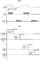
- Fig. 3 shows signal waveforms of respective parts representing operations of the sensor control device 1.
- the sensor control device 1, as shown in Fig. 2 includes respective functional sections consisting essentially of a drive unit 10, a driving signal generation section 20, a control unit 30 and a bus line 40.
- the driving signal generation section 20 is incorporated within the control unit 30.
- the drive unit 10 oscillates a transducer 3A included in each one of the ultrasonic sensors 3.
- the transducer 3A represents one (a transducer) incorporated within the ultrasonic sensor 3 and providing a function of converting an electric signal into an ultrasonic wave and a further function of converting an ultrasonic wave into an electric signal.
- the drive unit 10 oscillates the transducer 3A in accordance with a control signal from a control signal output section 31 which will be explained later herein.
- the drive unit 10 is provided in one-to-one relationship with the transducer 3A.
- the drive units 10 will be provided in correspondence in the number with the number of transducers 3A.
- a corresponding plurality (six) of the drive units 10 are provided also.
- the driving signal generation section 20 generates a driving signal capable of oscillating each one of a plurality of transducers 3A. As described above, such transducer 3A is included in each one of the plurality of ultrasonic sensors 3, and the plurality of transducers 3A are oscillated by a plurality of drive units 10 respectively. Thus, the driving signal generated by the driving signal generation section 20 corresponds to a signal for oscillating the transducer 3A included in each one of the plurality of drive units 10. The driving signal generation section 20 generates such driving signal and outputs it to the drive unit 10.
- Fig. 3 shows an example of such driving signal. In the example shown in Fig.
- a driving signal comprised of a pulse signal which becomes high in accordance with a period for oscillating the transducer 3A. Since the transducer 3A not only emits an ultrasonic wave, but also acquires its reflection wave, the driving signal is not outputted constantly, but outputted by predetermined time interval.
- the driving signal generation section 20 may output driving signals to the plurality of drive units 10 at one time, or may output a driving signal to each drive unit 10 individually with a time difference provided between the successive driving signals. In either case, as indicated by output waveforms in Fig. 3 , an ultrasonic wave is outputted from each ultrasonic sensor 3 in accordance with the driving signal.
- the drive unit 10 described above receives the driving signal from the driving signal generation section 20 and boosts the drivability of this driving signal by an unillustrated driver to drive the transducer 3A.
- control signal output section 31 in addition to the driving signal generation section 20 described above, the control signal output section 31 also is incorporated within the control unit 30.
- This control signal output section 31 is configured to output a control signal acting as an "input command" for the driving signal for the transducer 3A, for each one of the plurality of drive units 10.
- each one of the plurality of drive units 10 includes a driving signal acquisition section 11, a switch 12 and a signal processing unit 13.
- the driving signal acquisition section 11 acquires a driving signal generated by the driving signal generation section 20 described above.
- the switch 12 is provided between the driving signal acquisition section 11 and the ultrasonic sensor 3 (transducer 3A) and provides transmission of the driving signal from the driving signal acquisition section 11 to the transducer 3A and transmission blocking of the driving signal from the driving signal acquisition section 11 to the transducer 3A.
- the signal processing section 13 acquires a control signal outputted from the control signal output section 31 and controls opening/closing of the switch 12.
- the driving signal acquired by the signal processing section 13 from the control signal output section 31 is a signal indicating rendering of the switch 12 into its closed state
- the driving signal will be transmitted form the driving signal acquisition section 11 to the transducer 3A.
- the control signal acquired by the signal processing section 13 from the control signal output section 31 is a signal indicating rendering of the switch 12 into its opened state
- the driving signal from the driving signal acquisition section 11 to the transducer 3A will be blocked in its transmission.
- the bus line 40 connects the control unit 30 with the plurality of drive units 10 in the form of a daisy-chain.
- the control unit 30 incorporates therein the driving signal generation section 20 and the control signal output section 31 which were described above.
- the plurality of drive units 10 each includes the driving signal acquisition section 11, the switch 12 and the signal processing section 13 described above.
- the connection in the form of a daisy-chain refers to a method of connecting devices such as electric devices via a cable, more particularly, refers to series connection of the plurality of devices in the form of linkage thereof in a row.
- the control unit 30 and the plurality of drive units 10 are connected via such linkage thereof in a row.
- This bus line 40 is constituted of a twist-pair cable and with use of this twist-pair cable, bidirectional communication in LVDS (Low Voltage Differential Signaling) method is implemented for instance.
- the bus line 40 is laid inside the vehicle 2 as illustrated in Fig. 1 . Therefore, the control unit 30 and each one of the plurality of drive units 10 provided at the respective locations in the vehicle 2 can carry out transmission/reception of communication data.
- Fig. 4 shows an example of communication data to be subjected to the bidirectional communication between the control unit 30 and the respective plurality of drive units 10.
- communication data transmitted from the control unit 30 to one predetermined drive unit 10 among the plurality of drive units 10 is shown as a first transmission data.
- Communication data transmitted from the control unit 30 to a further predetermined drive unit 10 different from the above-described predetermined drive unit is shown as a second transmission data.
- Communication data transmitted from the above-described predetermined drive unit 10 to the control unit 30 is shown first reception data.
- Communication data transmitted from the above-described further predetermined drive unit 10 to the control unit 30 is shown as second reception data.
- each data will be communicated as being arranged timewise.
- the communication data are transmitted/received based on such time division as described above, it is possible to make delay occurring in the transmission/reception of each data negligible, by appropriate setting of the cycle of each data at some tens of micro seconds approximately for instance.
- each data in the instant embodiment is constituted of a data structure having a first band and a second band.
- the first band is a band that allows superimposition of audio data thereon, so that transmission and reception of audio data between audio modules mounted on the vehicle 2 is possible via the bus line 40.
- audio modules mounted on the vehicle 2 correspond to devices including a player for playing voice or sound, a speaker for outputting voice or sound, a microphone for collecting voice or sound, etc. Needless to say, other devices such as an acceleration sensor may be included also. And, transmission of audio signals between such devices is possible via the bus line 40.
- the bus line 40 may be used actually in transmission/reception of audio signals between such devices, or it may not be used.
- the second band is caused to include data representing identification information which allows identification of the device of transmission destination and the first band is caused to include audio data to be used in the device of the transmission destination.
- control signal outputted from the above-described control signal output section 31 is converted into control data based on this control signal and this control data as being included in the first band will be transmitted to the respective drive unit 10 from the control unit 30. Therefore, the signal processing section 13 acquires the control signal from the control data included in the first band of the first transmission data or the second transmission data.
- the driving signal generation section 20 is also incorporated within the control unit 30.
- the driving signal generated by the driving signal generation section 20 is converted into driving data based on this driving signal and this driving data is included in the second band distinct from the first band in the communication data (the first transmission data or the second transmission data described above) transmitted from the control unit 30 to the drive unit 10.
- the driving signal acquisition section 11 acquires the driving signal from the driving data included in the second band of the first transmission data or the second transmission data.
- the ultrasonic wave emitted from the ultrasonic sensor 3, when reaching an object if any of interest, will be reflected by that object and then returned to the transducer 3A, as indicated by the reflection wave shown in Fig. 3 .
- This reflection wave will be converted into an electric signal by the transducer 3A and the resultant converted electric signal will be transmitted to the signal processing section 13.
- the signal processing section 13 generates a reflection signal based on this electric signal (the reflection wave acquired by the ultrasonic sensor 3.
- this reflection signal is converted into reflection data based on the reflection signal and this will be included in the second band distinct from the first band in the communication data (the first reception data or the second reception data described above) to be transmitted from the drive unit 10 to the control unit 30.
- the reflection data will be transmitted via the bus line 40 from the drive unit 10 to an analysis section 50. Then, the analysis section 50 acquires the reflection signal from the reflection data included in the second band of the first reception data or the second reception data. And, based on this reflection signal, the analysis section 50 proceeds to calculate a distance from the vehicle 2 (the ultrasonic sensor 3) to the object of interest.
- the analysis section 50 determines or calculates presence/absence of any object of interest or the distance to the object of interest if any. More particularly, based on a time difference from the output of the ultrasonic wave as the output wave to the acquisition of its reflection wave, the distance to the object will be calculated.
- the drive unit 10 signal processing section 13
- the analysis section 50 amplifies the reflection wave and transmits to the analysis section 50 an electric signal configured to oscillate with a predetermined potential difference.
- bus line 40 as described above, a car (vehicle)-mounted audio bus is employed.
- car (vehicle)-mounted audio bus is mounted on the vehicle 2 and utilized for transmission/reception of audio signals.
- driving of the ultrasonic sensors 3 is controlled with use of this vehicle-mounted audio bus.
- the bus line 40 can employ the A2B (registered trademark). With this, weight reduction and cost reduction of the bus line 40 are made possible.
- the sensor control device 1 it becomes possible for the sensor control device 1 to control the plurality of ultrasonic sensors 3. Further, since the control unit 30 and the plurality of drive units 10 are connected to each other with use of the bus line 40 in the daisy-chain form, wiring arrangement/layout can be made simple, so that the further weight reduction of the sensor control device 1 is made possible.
- the bus line 40 was constituted of using a vehicle-mounted audio bus.
- the bus line 40 may be constituted of using a vehicle (car)-mounted network cable.
- the analysis section 50 is provided for calculating a distance to an object.
- an arrangement is possible with omission of such analysis section 50.
- it may be arranged such that the electric signal converted from the reflection wave by the transducer 3A is transmitted by the sensor control device 1 to a device which determines the distance to this object.
- the driving signal generation section 20 is incorporated within the control unit 30.
- the driving signal generation section 20 may be provided as a separate entity from the control unit 30. In such case too, driving data based on the driving signal can be transmitted via the bus line 40 to the drive unit 10. Further alternatively, the driving signal generation section 20 may be incorporated within the drive unit 10. In this case, the driving signal acquisition section 11 will acquire the driving signal and can output the driving signal to the transducer 3A according to the opening/closing control of the switch 12 by the signal processing section 13.
- the reflection data based on the reflection signal is included in the second band.
- the communication data has a data structure having a first band and a second band.
- the communication data may have a data structure having a further band other than the first band and the second band.
- This disclosure is applicable to a sensor control device configured to drive a plurality of ultrasonic sensors for detecting objects present in the surrounding of a vehicle.
Landscapes
- Engineering & Computer Science (AREA)
- Remote Sensing (AREA)
- Radar, Positioning & Navigation (AREA)
- Physics & Mathematics (AREA)
- Computer Networks & Wireless Communication (AREA)
- General Physics & Mathematics (AREA)
- Acoustics & Sound (AREA)
- Mechanical Engineering (AREA)
- Automation & Control Theory (AREA)
- Life Sciences & Earth Sciences (AREA)
- Human Computer Interaction (AREA)
- Transportation (AREA)
- Environmental & Geological Engineering (AREA)
- Geology (AREA)
- General Life Sciences & Earth Sciences (AREA)
- Geophysics (AREA)
- Measurement Of Velocity Or Position Using Acoustic Or Ultrasonic Waves (AREA)
- Traffic Control Systems (AREA)
Abstract
Description
- This disclosure relates to a sensor control device configured to drive a plurality of ultrasonic sensors for detecting objects present in the surrounding of a vehicle.
- Conventionally, for the purpose of assisting driving of a vehicle, a sensor for detecting an object present in the surrounding of a vehicle has been mounted on the vehicle. For instance, a plurality of such sensors are mounted on the vehicle in order to carry out detection over a wide area in the surrounding of the vehicle. As a technique relating to a vehicle mounting such plurality of sensors is known from e.g.
JP2003-141693A -
JP2003-141693A - In the technique disclosed in
JP2003-141693A JP2003-141693 - Embodiments of the present invention comprise a sensor control device that allows weight reduction.
- According to this disclosures, there is proposed a sensor control device configured to drive a plurality of ultrasonic sensors for detecting objects present in the surrounding of a vehicle, the sensor control device comprising:
- a plurality of drive units for oscillating respective transducers included in the plurality of ultrasonic sensors;
- a driving signal generation section for generating driving signals capable of oscillating the respective plurality of transducers;
- a control unit having a control signal output section for outputting, to each one of the plurality of drive units, a control signal as an input command for the driving signal to the respective transducer; and
- a bus line configured to connect the control unit to the plurality of drive units in form of a daisy-chain, the bus line being used for bidirectional communication of communication data between the control unit and the plurality of drive units based on preset time-division, the communication data being comprised of a data structure having a first band that allows superimposition of audio data thereon;
- wherein control data based on the control signal is included in the first band.
- In this case, the bus line usable for transmission and reception of audio data can be utilized for controlling of the ultrasonic sensors. Further, since the plurality of drive units are connected with use of a bus line, integration of controlling of the plurality of ultrasonic sensors is possible. Moreover, since the driving signal generation section and the plurality of drive units are connected via a daisy-chain configuration, simplification and weight reduction of connections are made possible also.
- Further, according to one preferred embodiment of the sensor control device, it may be arranged such that driving data based on the driving signal is included in a second band that is distinct from the first band and that also is included in the communication data transmitted from the control unit to the respective drive unit.
- In this case, even if the driving signal generation section is incorporated within the control unit, the driving signal can be transmitted to the respective drive unit appropriately.
- Further, according to one preferred embodiment of the sensor control device, it may be arranged such that the drive unit is configured to generate a reflection signal based on a reflection wave acquired by the ultrasonic sensor and reflection data based on the reflection signal is included in a second band that is distinct from the first band and that also is included in the communication data transmitted from the respective drive unit to the control unit.
- In this case, even if a functional section for analyzing the reflection wave is incorporated within the control unit, the reflection signal can be transmitted to the control unit appropriately.
- Further, according to one preferred embodiment of the sensor control device, the bus line comprises a vehicle-mounted audio bus.
- In this case, since an audio bus for communicating audio signals among audio devices mounted on the vehicle can be utilized for controlling of the ultrasonic sensors, cost reduction is made possible.
-
-
Fig. 1 shows an example of mounting ultrasonic sensors on a vehicle, -
Fig. 2 is a block diagram showing a configuration of a sensor control device, -
Fig. 3 shows signal waveforms of respective parts representing operations of the sensor control device, and -
Fig. 4 is a timing chart relating to transmission/reception of communication data. - A sensor control device relating to this disclosure seeks for weight reduction through ingenious control of driving of a plurality of ultrasonic sensors mounted on a vehicle. Next, a
sensor control device 1 relating to the instant embodiment will be explained. -
Fig. 1 is a view showing an example of mountingultrasonic sensors 3 controlled by thesensor control device 1 according to the instant embodiment on avehicle 2. Thevehicle 2 mounts a plurality of suchultrasonic sensors 3 configured to detect objects present in the surrounding of thisvehicle 2. Here, such "object" present in the surround of thevehicle 2 refers to an object which a driver of thevehicle 2 should be made aware of when traveling or parking thevehicle 2. Such object is not limited to a stationary object, but includes also a moving object such as other vehicle, a human, a bicycle, etc. Eachultrasonic sensor 3 is configured to detect presence/absence of such object or a distance to the object, based on a period from emission of an ultrasonic wave thereto and reflection and returning of the ultrasonic wave therefrom. As such ultrasonic sensor per se is known in the art, detailed explanation thereof will be omitted herein. - In the example shown in
Fig. 1 , theultrasonic sensors 3 are installed at six locations, namely, at a front left end portion, a front center portion, a front right end portion, a rear left end portion, a rear center portion and a rear right end portion of thevehicle 2. Needless to say, theultrasonic sensors 3 may be installed at other locations than the above or one or some of theultrasonic sensors 3 at the above six locations may be omitted. Thesensor control device 1 controls driving of suchultrasonic sensors 3. -
Fig. 2 is a block diagram schematically showing the configuration of thesensor control device 1.Fig. 3 shows signal waveforms of respective parts representing operations of thesensor control device 1. Thesensor control device 1, as shown inFig. 2 , includes respective functional sections consisting essentially of adrive unit 10, a drivingsignal generation section 20, acontrol unit 30 and abus line 40. In the instant embodiment, the drivingsignal generation section 20 is incorporated within thecontrol unit 30. - The
drive unit 10 oscillates atransducer 3A included in each one of theultrasonic sensors 3. Here, what is referred to as the "transducer 3A" above represents one (a transducer) incorporated within theultrasonic sensor 3 and providing a function of converting an electric signal into an ultrasonic wave and a further function of converting an ultrasonic wave into an electric signal. Assuch transducer 3A is known in the art, detailed explanation thereof will be omitted herein. Thedrive unit 10 oscillates thetransducer 3A in accordance with a control signal from a controlsignal output section 31 which will be explained later herein. Here, thedrive unit 10 is provided in one-to-one relationship with thetransducer 3A. Thus, thedrive units 10 will be provided in correspondence in the number with the number oftransducers 3A. In the instant embodiment, as a plurality (six) ofultrasonic sensors 3 are provided, a corresponding plurality (six) of thedrive units 10 are provided also. - The driving
signal generation section 20 generates a driving signal capable of oscillating each one of a plurality oftransducers 3A. As described above,such transducer 3A is included in each one of the plurality ofultrasonic sensors 3, and the plurality oftransducers 3A are oscillated by a plurality ofdrive units 10 respectively. Thus, the driving signal generated by the drivingsignal generation section 20 corresponds to a signal for oscillating thetransducer 3A included in each one of the plurality ofdrive units 10. The drivingsignal generation section 20 generates such driving signal and outputs it to thedrive unit 10.Fig. 3 shows an example of such driving signal. In the example shown inFig. 3 , there is shown a driving signal comprised of a pulse signal which becomes high in accordance with a period for oscillating thetransducer 3A. Since thetransducer 3A not only emits an ultrasonic wave, but also acquires its reflection wave, the driving signal is not outputted constantly, but outputted by predetermined time interval. The drivingsignal generation section 20 may output driving signals to the plurality ofdrive units 10 at one time, or may output a driving signal to eachdrive unit 10 individually with a time difference provided between the successive driving signals. In either case, as indicated by output waveforms inFig. 3 , an ultrasonic wave is outputted from eachultrasonic sensor 3 in accordance with the driving signal. Thedrive unit 10 described above receives the driving signal from the drivingsignal generation section 20 and boosts the drivability of this driving signal by an unillustrated driver to drive thetransducer 3A. - In the instant embodiment, in addition to the driving
signal generation section 20 described above, the controlsignal output section 31 also is incorporated within thecontrol unit 30. This controlsignal output section 31 is configured to output a control signal acting as an "input command" for the driving signal for thetransducer 3A, for each one of the plurality ofdrive units 10. - Here, in the instant embodiment, as shown in
Fig. 2 , each one of the plurality ofdrive units 10 includes a drivingsignal acquisition section 11, aswitch 12 and asignal processing unit 13. The drivingsignal acquisition section 11 acquires a driving signal generated by the drivingsignal generation section 20 described above. Theswitch 12 is provided between the drivingsignal acquisition section 11 and the ultrasonic sensor 3 (transducer 3A) and provides transmission of the driving signal from the drivingsignal acquisition section 11 to thetransducer 3A and transmission blocking of the driving signal from the drivingsignal acquisition section 11 to thetransducer 3A. Thesignal processing section 13 acquires a control signal outputted from the controlsignal output section 31 and controls opening/closing of theswitch 12. - Therefore, in case the control signal acquired by the
signal processing section 13 from the controlsignal output section 31 is a signal indicating rendering of theswitch 12 into its closed state, the driving signal will be transmitted form the drivingsignal acquisition section 11 to thetransducer 3A. Whereas, in case the control signal acquired by thesignal processing section 13 from the controlsignal output section 31 is a signal indicating rendering of theswitch 12 into its opened state, the driving signal from the drivingsignal acquisition section 11 to thetransducer 3A will be blocked in its transmission. - The
bus line 40 connects thecontrol unit 30 with the plurality ofdrive units 10 in the form of a daisy-chain. In the instant embodiment, thecontrol unit 30 incorporates therein the drivingsignal generation section 20 and the controlsignal output section 31 which were described above. The plurality ofdrive units 10 each includes the drivingsignal acquisition section 11, theswitch 12 and thesignal processing section 13 described above. The connection in the form of a daisy-chain refers to a method of connecting devices such as electric devices via a cable, more particularly, refers to series connection of the plurality of devices in the form of linkage thereof in a row. In the plurality of devices connected in the form of linkage thereof in a row, the more downstream side a device is disposed as seen from the output source of the signal, the more relaying via the other devices (i.e. the devices on the upstream side relative thereto). Various standards are known, respecting such daisy-chain type connection. But, as these are known in the art, explanation thereof will be omitted herein. In the instant embodiment, thecontrol unit 30 and the plurality ofdrive units 10 are connected via such linkage thereof in a row. - Between the
control unit 30 and each one of the plurality ofdrive unit 10, bidirectional communication of communication data is carried out via thebus line 40. Thisbus line 40 is constituted of a twist-pair cable and with use of this twist-pair cable, bidirectional communication in LVDS (Low Voltage Differential Signaling) method is implemented for instance. Thebus line 40 is laid inside thevehicle 2 as illustrated inFig. 1 . Therefore, thecontrol unit 30 and each one of the plurality ofdrive units 10 provided at the respective locations in thevehicle 2 can carry out transmission/reception of communication data. -
Fig. 4 shows an example of communication data to be subjected to the bidirectional communication between thecontrol unit 30 and the respective plurality ofdrive units 10. Here, for the sake of easier understanding, communication data transmitted from thecontrol unit 30 to onepredetermined drive unit 10 among the plurality ofdrive units 10 is shown as a first transmission data. Communication data transmitted from thecontrol unit 30 to a furtherpredetermined drive unit 10 different from the above-described predetermined drive unit is shown as a second transmission data. Communication data transmitted from the above-describedpredetermined drive unit 10 to thecontrol unit 30 is shown first reception data. Communication data transmitted from the above-described furtherpredetermined drive unit 10 to thecontrol unit 30 is shown as second reception data. - These respective data are communicated based on a preset time division. More particularly, as shown in
Fig. 4 , each data will be communicated as being arranged timewise. Incidentally, although the communication data are transmitted/received based on such time division as described above, it is possible to make delay occurring in the transmission/reception of each data negligible, by appropriate setting of the cycle of each data at some tens of micro seconds approximately for instance. - Further, each data in the instant embodiment is constituted of a data structure having a first band and a second band. The first band is a band that allows superimposition of audio data thereon, so that transmission and reception of audio data between audio modules mounted on the
vehicle 2 is possible via thebus line 40. Here, such audio modules mounted on thevehicle 2 correspond to devices including a player for playing voice or sound, a speaker for outputting voice or sound, a microphone for collecting voice or sound, etc. Needless to say, other devices such as an acceleration sensor may be included also. And, transmission of audio signals between such devices is possible via thebus line 40. Incidentally, thebus line 40 may be used actually in transmission/reception of audio signals between such devices, or it may not be used. - For instance, in case transmission/reception of audio data is carried out between a player and a speaker with using the
bus line 40 or in case transmission/reception of audio data is carried out between a microphone and a speaker, it is possible to arrange such that the second band is caused to include data representing identification information which allows identification of the device of transmission destination and the first band is caused to include audio data to be used in the device of the transmission destination. - The control signal outputted from the above-described control
signal output section 31 is converted into control data based on this control signal and this control data as being included in the first band will be transmitted to therespective drive unit 10 from thecontrol unit 30. Therefore, thesignal processing section 13 acquires the control signal from the control data included in the first band of the first transmission data or the second transmission data. - In the instant embodiment, the driving
signal generation section 20 is also incorporated within thecontrol unit 30. Here, the driving signal generated by the drivingsignal generation section 20 is converted into driving data based on this driving signal and this driving data is included in the second band distinct from the first band in the communication data (the first transmission data or the second transmission data described above) transmitted from thecontrol unit 30 to thedrive unit 10. Thus, the drivingsignal acquisition section 11 acquires the driving signal from the driving data included in the second band of the first transmission data or the second transmission data. - On the other hand, the ultrasonic wave emitted from the
ultrasonic sensor 3, when reaching an object if any of interest, will be reflected by that object and then returned to thetransducer 3A, as indicated by the reflection wave shown inFig. 3 . This reflection wave will be converted into an electric signal by thetransducer 3A and the resultant converted electric signal will be transmitted to thesignal processing section 13. Then, thesignal processing section 13 generates a reflection signal based on this electric signal (the reflection wave acquired by theultrasonic sensor 3. Further, this reflection signal is converted into reflection data based on the reflection signal and this will be included in the second band distinct from the first band in the communication data (the first reception data or the second reception data described above) to be transmitted from thedrive unit 10 to thecontrol unit 30. - The reflection data will be transmitted via the
bus line 40 from thedrive unit 10 to ananalysis section 50. Then, theanalysis section 50 acquires the reflection signal from the reflection data included in the second band of the first reception data or the second reception data. And, based on this reflection signal, theanalysis section 50 proceeds to calculate a distance from the vehicle 2 (the ultrasonic sensor 3) to the object of interest. - Based on the driving signal and the electric signal, the
analysis section 50 determines or calculates presence/absence of any object of interest or the distance to the object of interest if any. More particularly, based on a time difference from the output of the ultrasonic wave as the output wave to the acquisition of its reflection wave, the distance to the object will be calculated. Incidentally, while thetransducer 3A acquires the reflection wave, the drive unit 10 (signal processing section 13) amplifies the reflection wave and transmits to theanalysis section 50 an electric signal configured to oscillate with a predetermined potential difference. - Here, in the instant embodiment, as
such bus line 40 as described above, a car (vehicle)-mounted audio bus is employed. Such car (vehicle)-mounted audio bus is mounted on thevehicle 2 and utilized for transmission/reception of audio signals. In the inventivesensor control device 1, driving of theultrasonic sensors 3 is controlled with use of this vehicle-mounted audio bus. Specifically, thebus line 40 can employ the A2B (registered trademark). With this, weight reduction and cost reduction of thebus line 40 are made possible. - With the above-described configuration, it becomes possible for the
sensor control device 1 to control the plurality ofultrasonic sensors 3. Further, since thecontrol unit 30 and the plurality ofdrive units 10 are connected to each other with use of thebus line 40 in the daisy-chain form, wiring arrangement/layout can be made simple, so that the further weight reduction of thesensor control device 1 is made possible. - In the foregoing embodiment, the
bus line 40 was constituted of using a vehicle-mounted audio bus. However, thebus line 40 may be constituted of using a vehicle (car)-mounted network cable. - In the foregoing embodiment, it was explained that the
analysis section 50 is provided for calculating a distance to an object. However, an arrangement is possible with omission ofsuch analysis section 50. In this case, advantageously, it may be arranged such that the electric signal converted from the reflection wave by thetransducer 3A is transmitted by thesensor control device 1 to a device which determines the distance to this object. - In the foregoing embodiment, it was explained that the driving
signal generation section 20 is incorporated within thecontrol unit 30. Instead, the drivingsignal generation section 20 may be provided as a separate entity from thecontrol unit 30. In such case too, driving data based on the driving signal can be transmitted via thebus line 40 to thedrive unit 10. Further alternatively, the drivingsignal generation section 20 may be incorporated within thedrive unit 10. In this case, the drivingsignal acquisition section 11 will acquire the driving signal and can output the driving signal to thetransducer 3A according to the opening/closing control of theswitch 12 by thesignal processing section 13. - In the foregoing embodiment, it was explained that the reflection data based on the reflection signal is included in the second band. However, it is also possible to arrange such that the reflection data based on the reflection signal is transmitted from the
drive unit 10 to thecontrol unit 30 without using thebus line 40. - In the foregoing embodiment, it was explained that the communication data has a data structure having a first band and a second band. However, the communication data may have a data structure having a further band other than the first band and the second band.
- This disclosure is applicable to a sensor control device configured to drive a plurality of ultrasonic sensors for detecting objects present in the surrounding of a vehicle.
Claims (4)
- A sensor control device (1) configured to drive a plurality of ultrasonic sensors (3) for detecting objects present in the surrounding of a vehicle,
characterized by:a plurality of drive units (10) for oscillating respective transducers (3A) included in the plurality of ultrasonic sensors (3);a driving signal generation section (20) for generating driving signals capable of oscillating the respective plurality of transducers (3A);a control unit (30) having a control signal output section (31) for outputting, to each one of the plurality of drive units (10), a control signal as an input command for the driving signal to the respective transducer (3A); anda bus line (40) configured to connect the control unit (30) to the plurality of drive units (10) in form of a daisy-chain, the bus line (40) being used for bidirectional communication of communication data between the control unit (30) and the plurality of drive units (10) based on preset time-division, the communication data being comprised of a data structure having a first band that allows superimposition of audio data thereon;wherein control data based on the control signal is included in the first band. - The sensor control device (1) of claim 1, wherein driving data based on the driving signal is included in a second band that is distinct from the first band and that also is included in the communication data transmitted from the control unit (30) to the respective drive unit (10).
- The sensor control device (1) of claim 1 or 2, wherein:the drive unit (10) is configured to generate a reflection signal based on a reflection wave acquired by the ultrasonic sensor (3); andreflection data based on the reflection signal is included in a second band that is distinct from the first band and that also is included in the communication data transmitted from the respective drive unit (10) to the control unit (30).
- The sensor control device (1) of any one of claims 1-3, wherein the bus line (40) comprises a vehicle-mounted audio bus.
Applications Claiming Priority (1)
| Application Number | Priority Date | Filing Date | Title |
|---|---|---|---|
| JP2019030425A JP7155042B2 (en) | 2019-02-22 | 2019-02-22 | sensor controller |
Publications (1)
| Publication Number | Publication Date |
|---|---|
| EP3699635A1 true EP3699635A1 (en) | 2020-08-26 |
Family
ID=69156187
Family Applications (1)
| Application Number | Title | Priority Date | Filing Date |
|---|---|---|---|
| EP20150680.5A Ceased EP3699635A1 (en) | 2019-02-22 | 2020-01-08 | Sensor control device |
Country Status (4)
| Country | Link |
|---|---|
| US (1) | US11327174B2 (en) |
| EP (1) | EP3699635A1 (en) |
| JP (1) | JP7155042B2 (en) |
| CN (1) | CN111605560B (en) |
Families Citing this family (2)
| Publication number | Priority date | Publication date | Assignee | Title |
|---|---|---|---|---|
| US20220365210A1 (en) * | 2021-05-12 | 2022-11-17 | Gm Cruise Holdings Llc | Autonomous vehicle that comprises ultrasonic sensors |
| JPWO2025052811A1 (en) * | 2023-09-05 | 2025-03-13 |
Citations (5)
| Publication number | Priority date | Publication date | Assignee | Title |
|---|---|---|---|---|
| JP2003141693A (en) | 2001-11-01 | 2003-05-16 | Neptune:Kk | Vehicle safety checking device |
| US20160245914A1 (en) * | 2013-11-04 | 2016-08-25 | Denso Corporation | Sensor system, control device, and sensor |
| US20170222829A1 (en) * | 2016-01-29 | 2017-08-03 | Analog Devices, Inc. | Synchronous slave-to-slave communications |
| US20180015875A1 (en) * | 2016-07-13 | 2018-01-18 | Magna Electronics Inc. | Vehicle sensing system using daisy chain of sensors |
| DE102017118565A1 (en) * | 2017-08-15 | 2019-02-21 | Valeo Schalter Und Sensoren Gmbh | Method for operating a sensor arrangement in a motor vehicle on the basis of a DSI protocol |
Family Cites Families (22)
| Publication number | Priority date | Publication date | Assignee | Title |
|---|---|---|---|---|
| JP2988844B2 (en) * | 1995-04-25 | 1999-12-13 | シャープ株式会社 | Switching circuit for satellite broadcast converter. |
| JP2005003638A (en) | 2003-06-16 | 2005-01-06 | Fujikura Ltd | Obstacle detection device |
| JP3898187B2 (en) * | 2004-01-28 | 2007-03-28 | Necエレクトロニクス株式会社 | Switch circuit for converter for satellite broadcasting |
| US20050170808A1 (en) * | 2004-01-29 | 2005-08-04 | Hamilton Gordon E. | Radio interoperability system |
| CN100554997C (en) * | 2007-06-29 | 2009-10-28 | 厦门吉致电子有限公司 | Three-state digit transmission method in the parking assisting system |
| CN101983403B (en) * | 2008-07-29 | 2013-05-22 | 雅马哈株式会社 | Performance-related information output device, system provided with performance-related information output device, and electronic musical instrument |
| US8737638B2 (en) * | 2008-07-30 | 2014-05-27 | Yamaha Corporation | Audio signal processing device, audio signal processing system, and audio signal processing method |
| JP5670149B2 (en) * | 2010-06-09 | 2015-02-18 | 株式会社日立国際電気 | transceiver |
| CN102522090B (en) * | 2011-12-13 | 2013-11-13 | 我查查信息技术(上海)有限公司 | Method and device for sending information code and acquiring information code by audio frequency signal |
| KR101397763B1 (en) * | 2012-12-11 | 2014-05-20 | 삼성전기주식회사 | Apparatus and method for motor drive control, and motor using the same |
| JP6178994B2 (en) * | 2013-12-02 | 2017-08-16 | パナソニックIpマネジメント株式会社 | Relay device, linkage system, distribution device, processing method and program for relay device |
| JP6107689B2 (en) * | 2014-02-05 | 2017-04-05 | トヨタ自動車株式会社 | vehicle |
| DE102014107305A1 (en) * | 2014-05-23 | 2015-11-26 | Valeo Schalter Und Sensoren Gmbh | Parking assistance device for a motor vehicle |
| JP6470527B2 (en) | 2014-09-05 | 2019-02-13 | 株式会社デンソー | Object detection device |
| US10872049B2 (en) | 2016-01-29 | 2020-12-22 | Analog Devices, Inc. | GPIO-to-GPIO communication on a multi-node daisy-chained network |
| JP6672846B2 (en) * | 2016-02-03 | 2020-03-25 | 富士通株式会社 | Wireless device and phase control method |
| WO2018003462A1 (en) * | 2016-07-01 | 2018-01-04 | 日立オートモティブシステムズ株式会社 | Drive control device and control method for electric motor |
| CN106004659B (en) * | 2016-08-03 | 2017-08-04 | 安徽工程大学 | Vehicle Surrounding Environment Perception System and Control Method |
| CN206450271U (en) * | 2016-11-21 | 2017-08-29 | 成都安特诺科技有限公司 | Supersonic reflectoscope, bubble detection and removal device and bubble removal device |
| JP6930049B2 (en) * | 2017-01-16 | 2021-09-01 | Omデジタルソリューションズ株式会社 | Control method of drive device and image pickup device |
| CN108238102A (en) * | 2017-12-28 | 2018-07-03 | 清华大学苏州汽车研究院(吴江) | A kind of vehicle-mounted ultrasonic wave sensor system |
| KR102524292B1 (en) * | 2018-08-06 | 2023-04-21 | 현대자동차주식회사 | Speaker temperature controlling device for vehicle and method for controlling the same and vehicle including the same |
-
2019
- 2019-02-22 JP JP2019030425A patent/JP7155042B2/en active Active
-
2020
- 2020-01-08 EP EP20150680.5A patent/EP3699635A1/en not_active Ceased
- 2020-02-19 US US16/794,420 patent/US11327174B2/en active Active
- 2020-02-21 CN CN202010107175.8A patent/CN111605560B/en active Active
Patent Citations (5)
| Publication number | Priority date | Publication date | Assignee | Title |
|---|---|---|---|---|
| JP2003141693A (en) | 2001-11-01 | 2003-05-16 | Neptune:Kk | Vehicle safety checking device |
| US20160245914A1 (en) * | 2013-11-04 | 2016-08-25 | Denso Corporation | Sensor system, control device, and sensor |
| US20170222829A1 (en) * | 2016-01-29 | 2017-08-03 | Analog Devices, Inc. | Synchronous slave-to-slave communications |
| US20180015875A1 (en) * | 2016-07-13 | 2018-01-18 | Magna Electronics Inc. | Vehicle sensing system using daisy chain of sensors |
| DE102017118565A1 (en) * | 2017-08-15 | 2019-02-21 | Valeo Schalter Und Sensoren Gmbh | Method for operating a sensor arrangement in a motor vehicle on the basis of a DSI protocol |
Also Published As
| Publication number | Publication date |
|---|---|
| US11327174B2 (en) | 2022-05-10 |
| JP7155042B2 (en) | 2022-10-18 |
| US20200271781A1 (en) | 2020-08-27 |
| JP2020134390A (en) | 2020-08-31 |
| CN111605560B (en) | 2025-02-25 |
| CN111605560A (en) | 2020-09-01 |
Similar Documents
| Publication | Publication Date | Title |
|---|---|---|
| US9000902B2 (en) | Driver assistance system and method for operating same | |
| CN103370634B (en) | Driver assistance system for detecting objects in the surroundings of a vehicle | |
| CN102126466B (en) | Vehicle presence notification apparatus | |
| CN203385854U (en) | A semiconductor device and a sound distance measurement system | |
| US11327174B2 (en) | Sensor control device | |
| WO2004065792A3 (en) | Integrated control system for beam pump systems | |
| CN113267783A (en) | Apparatus, system and method for ultra-short range detection of obstacles | |
| JPH11342845A (en) | Train detection device, train position detection system, and train approach warning generation device | |
| US6804168B2 (en) | Method for measuring distance | |
| CN109515359A (en) | Ultrasonic noise in vehicle's passenger compartment is eliminated | |
| JP3474344B2 (en) | Mobile control device | |
| US9830124B2 (en) | Conversion of peripheral sensor interface signals into audio signals | |
| CN109799508A (en) | Vehicle blind zone monitoring device, method and system | |
| JPH10213658A (en) | Ultrasonic wave type obstacle detecting device for vehicle | |
| CN102138081B (en) | Method and arrangement for controlling sensors on a vehicle | |
| JP2666765B2 (en) | Acoustic target for underwater vehicles | |
| US11524629B2 (en) | Audible navigation indicator | |
| JPH03110490A (en) | Vehicle peripheral monitor device | |
| JP2000266849A (en) | Distance detection device | |
| KR20030010892A (en) | A warning system for automobile | |
| JPH08188102A (en) | Ultrasonic distance measuring equipment | |
| WO2009130725A1 (en) | Apparatus for detecting obstacles, in particular for assistance in driving and/or parking a vehicle | |
| CN106772399A (en) | Wireless exploration radar installations and its detection method | |
| JPH05336604A (en) | Vehicle coupling assisting system | |
| CN201622344U (en) | digital distance measuring device |
Legal Events
| Date | Code | Title | Description |
|---|---|---|---|
| PUAI | Public reference made under article 153(3) epc to a published international application that has entered the european phase |
Free format text: ORIGINAL CODE: 0009012 |
|
| STAA | Information on the status of an ep patent application or granted ep patent |
Free format text: STATUS: THE APPLICATION HAS BEEN PUBLISHED |
|
| AK | Designated contracting states |
Kind code of ref document: A1 Designated state(s): AL AT BE BG CH CY CZ DE DK EE ES FI FR GB GR HR HU IE IS IT LI LT LU LV MC MK MT NL NO PL PT RO RS SE SI SK SM TR |
|
| AX | Request for extension of the european patent |
Extension state: BA ME |
|
| STAA | Information on the status of an ep patent application or granted ep patent |
Free format text: STATUS: REQUEST FOR EXAMINATION WAS MADE |
|
| 17P | Request for examination filed |
Effective date: 20210222 |
|
| RBV | Designated contracting states (corrected) |
Designated state(s): AL AT BE BG CH CY CZ DE DK EE ES FI FR GB GR HR HU IE IS IT LI LT LU LV MC MK MT NL NO PL PT RO RS SE SI SK SM TR |
|
| STAA | Information on the status of an ep patent application or granted ep patent |
Free format text: STATUS: EXAMINATION IS IN PROGRESS |
|
| 17Q | First examination report despatched |
Effective date: 20210714 |
|
| STAA | Information on the status of an ep patent application or granted ep patent |
Free format text: STATUS: THE APPLICATION HAS BEEN REFUSED |
|
| 18R | Application refused |
Effective date: 20241112 |