EP3699603A1 - Procédé de surveillance d'une ligne électrique - Google Patents
Procédé de surveillance d'une ligne électrique Download PDFInfo
- Publication number
- EP3699603A1 EP3699603A1 EP19158605.6A EP19158605A EP3699603A1 EP 3699603 A1 EP3699603 A1 EP 3699603A1 EP 19158605 A EP19158605 A EP 19158605A EP 3699603 A1 EP3699603 A1 EP 3699603A1
- Authority
- EP
- European Patent Office
- Prior art keywords
- magnetic field
- inspection device
- power line
- camera
- mobile inspection
- Prior art date
- Legal status (The legal status is an assumption and is not a legal conclusion. Google has not performed a legal analysis and makes no representation as to the accuracy of the status listed.)
- Withdrawn
Links
Images

Classifications
-
- G—PHYSICS
- G01—MEASURING; TESTING
- G01R—MEASURING ELECTRIC VARIABLES; MEASURING MAGNETIC VARIABLES
- G01R15/00—Details of measuring arrangements of the types provided for in groups G01R17/00 - G01R29/00, G01R33/00 - G01R33/26 or G01R35/00
- G01R15/14—Adaptations providing voltage or current isolation, e.g. for high-voltage or high-current networks
- G01R15/142—Arrangements for simultaneous measurements of several parameters employing techniques covered by groups G01R15/14 - G01R15/26
-
- G—PHYSICS
- G01—MEASURING; TESTING
- G01R—MEASURING ELECTRIC VARIABLES; MEASURING MAGNETIC VARIABLES
- G01R15/00—Details of measuring arrangements of the types provided for in groups G01R17/00 - G01R29/00, G01R33/00 - G01R33/26 or G01R35/00
- G01R15/14—Adaptations providing voltage or current isolation, e.g. for high-voltage or high-current networks
- G01R15/20—Adaptations providing voltage or current isolation, e.g. for high-voltage or high-current networks using galvano-magnetic devices, e.g. Hall-effect devices, i.e. measuring a magnetic field via the interaction between a current and a magnetic field, e.g. magneto resistive or Hall effect devices
- G01R15/202—Adaptations providing voltage or current isolation, e.g. for high-voltage or high-current networks using galvano-magnetic devices, e.g. Hall-effect devices, i.e. measuring a magnetic field via the interaction between a current and a magnetic field, e.g. magneto resistive or Hall effect devices using Hall-effect devices
-
- G—PHYSICS
- G01—MEASURING; TESTING
- G01R—MEASURING ELECTRIC VARIABLES; MEASURING MAGNETIC VARIABLES
- G01R15/00—Details of measuring arrangements of the types provided for in groups G01R17/00 - G01R29/00, G01R33/00 - G01R33/26 or G01R35/00
- G01R15/14—Adaptations providing voltage or current isolation, e.g. for high-voltage or high-current networks
- G01R15/20—Adaptations providing voltage or current isolation, e.g. for high-voltage or high-current networks using galvano-magnetic devices, e.g. Hall-effect devices, i.e. measuring a magnetic field via the interaction between a current and a magnetic field, e.g. magneto resistive or Hall effect devices
- G01R15/205—Adaptations providing voltage or current isolation, e.g. for high-voltage or high-current networks using galvano-magnetic devices, e.g. Hall-effect devices, i.e. measuring a magnetic field via the interaction between a current and a magnetic field, e.g. magneto resistive or Hall effect devices using magneto-resistance devices, e.g. field plates
-
- G—PHYSICS
- G01—MEASURING; TESTING
- G01R—MEASURING ELECTRIC VARIABLES; MEASURING MAGNETIC VARIABLES
- G01R31/00—Arrangements for testing electric properties; Arrangements for locating electric faults; Arrangements for electrical testing characterised by what is being tested not provided for elsewhere
- G01R31/08—Locating faults in cables, transmission lines, or networks
- G01R31/081—Locating faults in cables, transmission lines, or networks according to type of conductors
- G01R31/085—Locating faults in cables, transmission lines, or networks according to type of conductors in power transmission or distribution lines, e.g. overhead
-
- G—PHYSICS
- G06—COMPUTING; CALCULATING OR COUNTING
- G06T—IMAGE DATA PROCESSING OR GENERATION, IN GENERAL
- G06T7/00—Image analysis
- G06T7/0002—Inspection of images, e.g. flaw detection
-
- H—ELECTRICITY
- H04—ELECTRIC COMMUNICATION TECHNIQUE
- H04N—PICTORIAL COMMUNICATION, e.g. TELEVISION
- H04N23/00—Cameras or camera modules comprising electronic image sensors; Control thereof
- H04N23/70—Circuitry for compensating brightness variation in the scene
- H04N23/73—Circuitry for compensating brightness variation in the scene by influencing the exposure time
-
- H—ELECTRICITY
- H04—ELECTRIC COMMUNICATION TECHNIQUE
- H04N—PICTORIAL COMMUNICATION, e.g. TELEVISION
- H04N7/00—Television systems
- H04N7/18—Closed-circuit television [CCTV] systems, i.e. systems in which the video signal is not broadcast
- H04N7/188—Capturing isolated or intermittent images triggered by the occurrence of a predetermined event, e.g. an object reaching a predetermined position
-
- G—PHYSICS
- G01—MEASURING; TESTING
- G01R—MEASURING ELECTRIC VARIABLES; MEASURING MAGNETIC VARIABLES
- G01R15/00—Details of measuring arrangements of the types provided for in groups G01R17/00 - G01R29/00, G01R33/00 - G01R33/26 or G01R35/00
- G01R15/14—Adaptations providing voltage or current isolation, e.g. for high-voltage or high-current networks
- G01R15/20—Adaptations providing voltage or current isolation, e.g. for high-voltage or high-current networks using galvano-magnetic devices, e.g. Hall-effect devices, i.e. measuring a magnetic field via the interaction between a current and a magnetic field, e.g. magneto resistive or Hall effect devices
- G01R15/207—Constructional details independent of the type of device used
-
- G—PHYSICS
- G06—COMPUTING; CALCULATING OR COUNTING
- G06T—IMAGE DATA PROCESSING OR GENERATION, IN GENERAL
- G06T2207/00—Indexing scheme for image analysis or image enhancement
- G06T2207/20—Special algorithmic details
- G06T2207/20212—Image combination
-
- G—PHYSICS
- G06—COMPUTING; CALCULATING OR COUNTING
- G06T—IMAGE DATA PROCESSING OR GENERATION, IN GENERAL
- G06T2207/00—Indexing scheme for image analysis or image enhancement
- G06T2207/30—Subject of image; Context of image processing
- G06T2207/30232—Surveillance
Definitions
- the invention relates to a method for monitoring a power line carrying an electrical current, a mobile inspection device, a computer program and a machine-readable storage medium.
- the disclosure document DE 10 2015 221 600 A1 discloses a method for monitoring and managing a power distribution system.
- the known method comprises receiving sensor measurement data which are acquired by a mobile inspection device during an inspection of a power distribution system element in a power distribution system.
- the mobile inspection device comprises infrared cameras and audio sensors which are set up to detect electrical resonances, hum or vibrations.
- the object on which the invention is based is to be seen in providing a concept for the efficient monitoring of a power line carrying an electrical current.
- a computer program comprising instructions which, when the computer program is executed by a computer, cause the computer to carry out a method according to the first aspect.
- a machine-readable storage medium is provided on which the computer program according to the third aspect is stored.
- the invention is based on the knowledge that insulation damage in a power line carrying an electrical current can lead to voltage flashovers.
- Such flashovers can be accompanied by one or more flashes of light.
- Such flashes of light can be recorded efficiently by means of a camera, so that this advantageously makes it possible to efficiently detect insulation damage.
- Voltage flashovers depend in particular on the electrical current flowing through the power line.
- the electric current through the power line creates a magnetic field that depends on the electric current.
- information for example a phase, a frequency (in the case of an alternating current) and / or a current intensity, can thus advantageously be obtained about the electrical current. Based on this information, it can be efficiently determined, for example, at which location the power line and / or at which point at which point in time a voltage flashover and thus a flash of light can be expected, provided that the power line at this location has insulation damage.
- the mobile inspection device is an element selected from the following group of vehicles: land vehicle, watercraft, aircraft.
- An aircraft is a drone, for example.
- the mobile inspection device is designed to be remotely controlled.
- the mobile inspection device is set up for autonomous operation in addition to or instead of remote control.
- several magnetic field sensors and / or several cameras are provided. Statements made in connection with a camera and / or a magnetic field sensor apply analogously to several cameras and / or several magnetic field sensors and vice versa.
- the electrical current is an alternating current.
- the electrical current is an alternating current, a phase and / or a frequency of the electrical current being determined based on the measured magnetic field, the camera recording the image based on the determined phase and / or the determined frequency .
- Voltage flashovers generally occur in the vicinity of a maximum of a network voltage, which in the case of an alternating current is an alternating voltage, which is responsible for the flow of the electrical current.
- a location and / or a point in time can thus advantageously be determined at which a voltage flashover and thus a flash of light could occur in the event of insulation damage at this location.
- the camera can thus be operated efficiently, for example to take a picture at the determined time and / or at the determined location.
- the recording of an image comprises a multiple exposure of a frame.
- the recording comprises exposing a plurality of individual frames which are added.
- the plurality of frames are shifted for addition to one another in order to compensate for a movement of the mobile inspection device.
- the addition of the multiple frames is carried out using a stitching method, for example.
- a "Region of Interest (ROI)" in German an area of interest (here the specific sub-area), is determined as the area of the image sensor to be read based on the orientation of the magnetic field sensor relative to the power line.
- the camera comprises an image sensor.
- the camera is a UV camera.
- the camera is therefore preferably set up to detect electromagnetic radiation in the ultraviolet (UV) range.
- the camera is therefore set up in particular to record UV images.
- the mobile inspection device comprises at least one acoustic sensor (i.e. one or more acoustic sensors) by means of which airborne sound is measured, the measured airborne sound being evaluated based on the determined phase and / or the determined frequency to detect an acoustic signal resulting from a voltage flashover.
- acoustic sensor i.e. one or more acoustic sensors
- Voltage flashovers are usually accompanied by acoustic emissions, which can be recorded as an acoustic signal by means of the acoustic sensor. Analogous to the flash of light, these acoustic emissions depend on the voltage flashover and, as a result, on the electrical current, so that, analogous to the flash of light, a statement can be made about the location and / or to which by measuring the magnetic field generated by the flowing electrical current Time can be expected with an acoustic signal.
- the acoustic signal will, for example, correlate with a maximum of the mains voltage.
- a plurality of acoustic sensors are provided, with triangulation being carried out based on the respective measured airborne sound in order to locate a source of the acoustic signal.
- a source of the acoustic signal can be efficiently located.
- a source of the acoustic signal is therefore located based on the implementation of the triangulation.
- a Locating means that a position or a location or a direction in relation to the mobile inspection device is determined on the power line.
- a phase position of the electrical current is determined at the time of the detected voltage flashover, a breakdown voltage being determined based on the determined phase position and a nominal voltage of the power line.
- the recorded image is evaluated in order to detect a voltage flashover, with the mobile inspection device and / or the camera being controlled in such a way that a location of a source of the detected voltage flashover continues to be recorded by the camera when a voltage flashover is detected can.
- control signals for controlling a movement of the mobile inspection device are generated and output in order to move the mobile inspection device along a course of the power line.
- the power line is a high voltage line.
- the power line has insulation.
- the power line is a land line.
- the power line is part of a bundle of power lines, for example of three power lines.
- a network frequency is 50 Hz or 60 Hz.
- the mobile inspection device according to the second aspect is set up to carry out the method according to the first aspect.
- monitoring of a high-voltage line is described by way of example as a power line carrying electrical current according to the concept described here.
- Known mobile inspection devices include, for example, GPS sensors or inertial sensors in order to detect the movement of the inspection device in order to generate position information for a controller, for example for a flight controller in the case of a drone.
- the controller then controls the inspection device via a path control from an actual position on a target path of a planned trajectory.
- the mobile inspection device also uses, in particular, at least one further measurement signal from the measurement object (here the high-voltage line) in order to fulfill the control task of active and possibly automatic tracking of the measurement object with greater accuracy.
- at least one further measurement signal from the measurement object here the high-voltage line
- an alternating electrical current flows. This generates an electromagnetic field that is detected by at least one magnetic field sensor of the mobile inspection device.
- the (electro) magnetic signal to be measured results as follows:
- the high-voltage lines have, for example, 3 phases that are mutually offset by 120 ° in phase.
- the mains frequency is 50 or 60 Hz.
- Shifting the 2 from the exponent to the argument from the sine is precisely the frequency doubling that represents the transition from the amplitude of the electrical alternating voltage to the electrical power.
- the mobile inspection device can thus also functionally couple itself to the function of the high-voltage line with a sufficiently fast magnetic field sensor. This has the technical advantage that functional damage, in particular Damage to the insulation that results in voltage flashovers can be detected.
- These voltage flashovers are usually accompanied by a flash of light that contains large amounts of UV radiation due to the excitation and ionization of air molecules.
- the UV radiation of the light flash can be used to detect a corona effect.
- UV camera (s) can be used for this.
- the corona is a voltage breakdown in the air.
- the voltage flashover can occur from a certain voltage (the breakdown voltage) depending on the size of the defect in the insulation. Smaller defects will only appear at higher voltages. Maximum sensitivity so one has to consider it in the vicinity of the maximum of the mains voltage - for each of the phases separately! Every isolator only sits in one phase.
- the corona ignites at a certain voltage.
- the air is then ionized in the arc, which produces additional ions and thus additional conductive ions. This increases the conductivity in the ionized air and the ions move in the electric field. In doing so, they collide with other molecules.
- the exposure of the camera advantageously begins in particular with or (very) shortly before the maximum of the mains voltage on the line of one of the phases.
- the beginning of the exposure is 1/3 of the exposure time and / or in particular 2/3 of the exposure time after the maximum.
- a measurement of the magnetic field is provided using a magnetic field sensor.
- a measurement of a magnetic field by means of a magnetic field sensor is based, for example, on the Hall effect and / or the magnetoresistive (MR) effect, for example the AMR (anisotropic magnetoresistive) effect and / or the GMR (giant magnetoresistive) effect.
- MR magnetoresistive
- Magnetic field sensors which are based on the GMR effect, have many advantages and, due to the automotive industry, are robust mass-produced goods and very inexpensive. They have also the advantage that a temperature can be measured implicitly and this can even be canceled out in the measurement. This means that multifunctional sensors are available for indirect magnetic field measurements.
- magnetoresistive magnetic field sensors already measure a field direction of the magnetic field in one plane.
- Hall sensors only measure a projection of the magnetic field onto a semiconductor component of the Hall sensor in a direction perpendicular to the direction of the current.
- 2 Hall sensors are required to replace an MR sensor.
- At least 2 MR sensors are used, these being arranged in such a way that a 3D field direction can be measured in space.
- the MR sensors are also fast, so they can also measure the frequency of the magnetic field and thus the network frequency efficiently.
- an optical quantum magnetic field sensor is provided as a magnetic field sensor, which is advantageously very sensitive and is therefore very suitable for the concept described here.
- MR and Hall sensors also have the advantage of low energy consumption.
- the magnetic field around an elongated conductor shows up in concentric rings around the conductor, where the direction of the field lines is then reversed from half-wave to half-wave.
- the conductor is perpendicular to the plane of a field line, i.e. in the normal plane of the field direction at the measurement location. If you measure the field direction at two locations, the normal planes intersect in the axis of the conductor when the field is not distorted by dielectrics and interference effects. The fact that there is no distortion in air is assumed here as a first approximation.
- the mobile inspection device has two magnetic field sensors with a known spatial arrangement and orientation. The location of the high-voltage line can then be determined via triangulation and thus the distance to the inspection device can also be determined simply via the angular relationship of the field directions in the measuring plane.
- the field direction then changes from phase to phase of the high-voltage line, since the individual conductors in the high-voltage line are spatially separated and the field strength modulates sinusoidally. This is taken into account in the evaluation, for example.
- the camera can then be triggered, for example, and the images can then be taken efficiently at the right time, when a corona discharge can also be expected in the respective phase.
- the camera does not have a recording speed (frame rate) of 300 Hz, for example, it is provided that the triggering is used intelligently and the recording speed of the camera is cleverly used in such a way that the 6 points in time for the network phase are caught as quickly as possible and as little as possible possible waiting time between the frames. Since the time intervals from one peak to the next are only 3 ms, you should max. times have to wait 6 ms, which is around 160 Hz frame rate. If the camera is even slower, the waiting time is no longer really important.
- the magnetic field sensor for example the MR sensor
- the camera for example with the UV camera
- the magnetic field sensor can provide the camera with the information about the image height at which a corona effect is to be expected .
- Fast and real-time defect detection are possible - for example, via coupled FPGA-based image evaluation in the mobile inspection device itself.
- direction information can then be provided to the FPGA, which then uses this for an ROI evaluation in the image. Evaluating and reading out and processing less data reduces the electrical energy consumption of the mobile inspection device and can thus protect an energy store, for example an accumulator, of the inspection device.
- the technical effect can be brought about that a range of the inspection device can be increased efficiently.
- the rapid detection of the defect also has the technical advantage that a close-up of the defect can be taken immediately after the defect has been detected in order to carry out an immediate detailed check.
- a close-up movement path can be stored in a control of the inspection device, which path is automatically flown or driven off when a defect is detected.
- a real-time evaluation with low latency can thus advantageously be carried out.
- Insulation defects which are usually the most critical faults or defects, can thus be identified quickly and reliably. Insulation defects immediately lead to line losses and thus immediately cost the network operator money. These disadvantages can also be minimized due to the rapid defect detection.
- a plurality of magnetic sensors are provided which each measure a field direction of the magnetic field, so that a triangulation is carried out based on the respective measured field directions in order to determine a location or a position of the power line and optionally also a distance to the or the power lines.
- a movement of the inspection device is controlled based on the location of the power line and optionally on the distance.
- a flight in particular an altitude and a position, is controlled.
- a distance to the power line can be kept constant so that the power line can be picked up regardless of any deflection, which results in an approximately constant size of the individual components in the image. This further improves the recording and processing of the measurement data or measurement signals. Furthermore, the signals of the magnetic field sensor can be evaluated more easily and with less computational effort than image evaluation, which then enables greater ranges with the same battery capacity given the limited electrical energy of a mobile inspection device.
- the evaluation of the magnetic field measurement and the evaluation of the recorded image are carried out while the mobile inspection device is still in operation, which is also called “on the fly” (in the case of an aircraft) or “live” evaluation can be designated.
- the camera can therefore be a mono camera and does not have to be a stereo camera. Orientation can take place via the image and the magnetic signal can be used to determine a distance and a direction to the power line.
- the camera is a TOF camera.
- a "time of flight” measurement is therefore carried out here by means of the camera.
- “Time of flight” can be translated as “running time”.
- a transit time measurement is therefore carried out. This also increases data security through an independent measuring principle.
- the mobile inspection device comprises an adjustable camera holder to which the camera is attached.
- the adjustable camera holder is controlled based on the recorded image and / or based on the measured magnetic field in such a way that a certain area or a certain location is held in the image, that is, is held in the recording area of the camera.
- Such an active control advantageously enables the safety areas at the edge of the image to be reduced against unintentional clipping, so that either the magnification and thus the resolution can be increased with the same sensor size of the camera or the sensor size can be reduced in order to increase the amount of data to reduce.
- the mobile inspection device comprises an acoustic sensor, which can for example be capacitive, inductive, piezoelectric or optical, for detecting the airborne sound.
- a corona can also be detected acoustically. As the air is briefly heated up during the discharge, acoustic signals are also generated. These can then be detected efficiently with the sound sensor.
- the phase position of the alternating voltage is used, which is determined by means of the magnetic field sensor, in order to determine a point in time when the corona can be detected acoustically by means of the acoustic sensor. Based on the specific phase position of the alternating voltage, an estimate is therefore provided of the phase position at which a breakdown occurs before a maximum of the voltage or the energy of the magnetic field.
- the nominal voltage of the power line is known.
- the breakdown voltage can advantageously be estimated efficiently and the severity or size of the defect can thus be determined efficiently.
- a breakdown voltage is determined or estimated based on the nominal voltage of the power line.
- a size or a severity of the defect in the insulation of the power line is determined based on the determined breakdown voltage or based on the estimated breakdown voltage.
- acoustic sensors are provided, these being arranged in a known geometry.
- a triangulation is carried out based on the known geometry and the respective measured acoustic signals in order to determine a location of the source of the acoustic signals.
- the acoustic signals are referenced or correlated with the magnetic signals in order to avoid possible false detections.
- acoustic signals are used or taken into account that are recognized or detected in a rising range of the alternating voltage. If it is a defect, the signal should be recognized in every full period of the voltage.
- the signals of the positive and negative half-wave can be different at the time of occurrence. This asymmetry can also be evaluated as a characteristic of the defect.
- the coincidence of the sound signal and the magnetic phase position can be implemented as a two-phase measurement.
- This two-phase measurement is used, on the one hand, to measure more precisely and, on the other hand, to reliably detect incorrect measurements.
- the coupling can be optimized and / or minimized in various ways.
- the drive technology and / or the control technology do not have any electrical signals in the range of the line frequency and its harmonics.
- the measurement signals can be suitably filtered with a bandpass for the network frequency.
- the control technology is designed in such a way that the network frequency and the harmonics are not used in the control system and so no interference signal is generated in this frequency range.
- drive technology which, for example, can include control of one or more drives. In the case of an aircraft, for example, one or more propellers can be provided that these are driven at frequencies different from the mains frequency and harmonics.
- a power line in the sense of the description can be sheathed or not sheathed, so it can be free of sheathing.
- Insulation can be formed, for example, as a jacket around the power line.
- An insulation may, for example, comprise an insulator on a power pole or may be formed as such an insulator, wherein the power line is attached to the power pole.
- a defect in insulation of the power line can therefore be, for example, a defect in the insulator and / or in the sheathing.
- FIG. 11 shows a flow chart of a method for monitoring a power line carrying an electrical current according to a first embodiment.
- the method is carried out using a mobile inspection device.
- the mobile inspection device comprises a magnetic field sensor and a camera.
- FIG. 10 shows a flow chart of a method for monitoring a power line carrying an electrical current according to a second embodiment.
- the method is carried out using a mobile inspection device.
- the mobile inspection device comprises a magnetic field sensor, a camera and an acoustic sensor, by means of which an airborne sound can be measured.
- the method includes measuring 201 a magnetic field generated by the current by means of the magnetic field sensor.
- the method further comprises determining 203 a phase and a frequency of the electric current based on the measured magnetic field.
- the method includes measuring 205 an airborne sound by means of the acoustic sensor.
- the method includes evaluating 207 the measured airborne sound based on the determined phase and the determined phase Frequency to detect an acoustic signal resulting from a voltage flashover.
- the method comprises recording 209 an image of the power line by means of the camera as a function of the measured magnetic field.
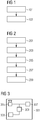
- FIG 3 shows a mobile inspection device 301 for monitoring a power line carrying an electric current.
- the mobile inspection device 301 comprises a magnetic field sensor 303 which is set up to measure a magnetic field generated by the current.
- the mobile inspection device 301 further comprises a camera 305 which is set up to record an image of the power line as a function of the measured magnetic field.
- the mobile inspection device 301 further comprises an acoustic sensor 307 which is set up to detect or measure an airborne sound.
- the mobile inspection device 301 further comprises a controller 309 which is set up to control the mobile inspection device 301.
- the controller 309 is configured to control a movement of the mobile inspection device 301.
- the controller 309 is e.g. set up to control the mobile inspection device 301 based on the measured magnetic field and / or based on the recorded image and / or based on the measured airborne sound.
- control device 309 is set up to determine recording parameters for the camera 303 based on the measured magnetic field.
- control device 309 is set up to control the camera 303 based on the determined recording parameters in order to record an image of the power line.
- Recording parameters include, for example: an exposure time and / or a trigger time.
- the controller 309 is e.g. set up to execute or control one or more steps of the method according to the first aspect.
- the mobile inspection device 301 is an aircraft, for example a drone, for example a quadrocopter.
- the controller 309 is e.g. a flight controller.
- FIG 4 shows a machine-readable storage medium 401.
- a computer program 403 is stored on the machine-readable storage medium 401.
- the computer program 403 comprises commands which, when the computer program 403 is executed by a computer, for example by the control device 309 of the mobile inspection device 301 according to FIG 3 to cause this to carry out a method according to the first aspect.
- FIG 5 shows a mobile inspection device 501 according to a second embodiment, wherein the mobile inspection device 501 is formed as a drone.
- the drone 501 comprises a magnetic field sensor 503, a camera 505, and a control device 507.
- the control device 507 is designed as a flight control device. This means that the control device 507 can control a flight of the drone 501.
- the drone 501 monitors a power line 509 which carries an electrical current and which comprises an insulation 515.
- the electric current flowing through the power line 509 is an alternating current.
- the power line 509 runs between a first power pole 511 and a second power pole 513, the power line 509 being attached to the first power pole 511 and to the second power pole 513.
- the insulation 515 comprises a defect 517 at which voltage breakdowns or voltage flashovers can occur.
- This flashover is accompanied by a flash of light 519, which can also be referred to as a corona.
- the magnetic field sensor 505 measures a magnetic field generated by the electric current, so that a phase and a frequency of the electric current can be determined from it.
- the camera 503 can thus be operated in an efficient manner such that it takes one or more images of the power line 509 at the determined point in time.
- control device 507 controls the drone 501 in such a way that it controls the determined location in such a way that the camera 503 can also capture this location.
- One example is the reliable detection of corona effects also on the side facing away from the camera when using a sound sensor (acoustic sensor) which can acoustically detect a voltage flashover, in which case e.g. a coincidence of acoustic and magnetic signals is used and / or the sound signal is checked for quasi-periodicity with the mains frequency or even twice the mains frequency in order to check the measured sound signal to determine whether a voltage flashover is the source of the sound signal or not .
- This can e.g. take place with a continuously carried out Fourier transformation, which then has a maximum at the corresponding frequencies.
- the multi-modal measurement makes the measurement more reliable, for example with the approach of a two-phase measurement. More modalities usually gain additional data or more precise data with regard to at least one feature, here in particular the detection of a defect in the insulation.
- the detection of the functional status is carried out by means of the magnetic field sensor. In certain weather conditions, this can also be carried out based on an acoustic measurement by means of the acoustic sensor in order to detect a system hum.
- the acoustic measurement can also detect defects on insulator components (generally: insulation) which, as seen by the camera, lie on the rear side of the component.
- insulation generally: insulation
- the sound sensor is sensitive to aspects of the function since it can pick up the sound signals that e.g. can happen in the event of an insulation fault with discharge. The verification of the sound signal can be ensured via the function of the line, since one also knows - a priori - that discharges only occur at higher voltages.
- the multi-modal detection together with the coupling to the functional parameters of the measurement object can increase or even fundamentally expand the detection capability of the measuring system.
- New applications can be offered specifically for the application of monitoring a power line with detection of defects, such as: Locating the power line in the room.
- Improvement of the signal-to-noise ratio of the measurements by adapting the measurement times to the functional state of the measurement object (in the sense of a lock-in principle from measurement technology), e.g. taking an image of a location on the power line while a phase of the electrical current is present at this location passes through a maximum.
Priority Applications (6)
| Application Number | Priority Date | Filing Date | Title |
|---|---|---|---|
| EP19158605.6A EP3699603A1 (fr) | 2019-02-21 | 2019-02-21 | Procédé de surveillance d'une ligne électrique |
| EP20706987.3A EP3899554B1 (fr) | 2019-02-21 | 2020-02-14 | Procédé de surveillance d'une ligne électrique |
| ES20706987T ES2963891T3 (es) | 2019-02-21 | 2020-02-14 | Procedimiento de vigilancia de un conducto de corriente eléctrica |
| CN202080015616.XA CN113474665B (zh) | 2019-02-21 | 2020-02-14 | 用于监控电导线的方法 |
| US17/431,158 US11796570B2 (en) | 2019-02-21 | 2020-02-14 | Method for monitoring a power line |
| PCT/EP2020/053880 WO2020169468A1 (fr) | 2019-02-21 | 2020-02-14 | Procédé pour la surveillance d'une ligne électrique |
Applications Claiming Priority (1)
| Application Number | Priority Date | Filing Date | Title |
|---|---|---|---|
| EP19158605.6A EP3699603A1 (fr) | 2019-02-21 | 2019-02-21 | Procédé de surveillance d'une ligne électrique |
Publications (1)
| Publication Number | Publication Date |
|---|---|
| EP3699603A1 true EP3699603A1 (fr) | 2020-08-26 |
Family
ID=65520169
Family Applications (2)
| Application Number | Title | Priority Date | Filing Date |
|---|---|---|---|
| EP19158605.6A Withdrawn EP3699603A1 (fr) | 2019-02-21 | 2019-02-21 | Procédé de surveillance d'une ligne électrique |
| EP20706987.3A Active EP3899554B1 (fr) | 2019-02-21 | 2020-02-14 | Procédé de surveillance d'une ligne électrique |
Family Applications After (1)
| Application Number | Title | Priority Date | Filing Date |
|---|---|---|---|
| EP20706987.3A Active EP3899554B1 (fr) | 2019-02-21 | 2020-02-14 | Procédé de surveillance d'une ligne électrique |
Country Status (5)
| Country | Link |
|---|---|
| US (1) | US11796570B2 (fr) |
| EP (2) | EP3699603A1 (fr) |
| CN (1) | CN113474665B (fr) |
| ES (1) | ES2963891T3 (fr) |
| WO (1) | WO2020169468A1 (fr) |
Families Citing this family (3)
| Publication number | Priority date | Publication date | Assignee | Title |
|---|---|---|---|---|
| US11368002B2 (en) * | 2016-11-22 | 2022-06-21 | Hydro-Quebec | Unmanned aerial vehicle for monitoring an electrical line |
| CN114966718B (zh) * | 2022-05-12 | 2023-04-28 | 国网安徽省电力有限公司马鞍山供电公司 | 一种适配无人机的测距装置及使用方法 |
| CN117353466B (zh) * | 2023-12-06 | 2024-03-12 | 天津大学 | 基于图像识别的配网电力设备故障检测装置及其检测方法 |
Citations (4)
| Publication number | Priority date | Publication date | Assignee | Title |
|---|---|---|---|---|
| EP2495166A1 (fr) * | 2011-03-03 | 2012-09-05 | Asociacion de la Industria Navarra (AIN) | Système robotique aérien pour l'inspection des lignes aériennes de puissance |
| US20150225002A1 (en) * | 2015-04-22 | 2015-08-13 | Electro-Motive Diesel, Inc. | Railway inspection system |
| US20150353196A1 (en) * | 2014-06-09 | 2015-12-10 | Izak Jan van Cruyningen | UAV Constraint in Overhead Line Inspection |
| DE102015221600A1 (de) | 2014-11-20 | 2016-05-25 | Abb Technology Ag | Verfahren, systeme und computerlesbare medien zum überwachen und verwalten eines stromverteilungssystems |
Family Cites Families (35)
| Publication number | Priority date | Publication date | Assignee | Title |
|---|---|---|---|---|
| US4818990A (en) | 1987-09-11 | 1989-04-04 | Fernandes Roosevelt A | Monitoring system for power lines and right-of-way using remotely piloted drone |
| US6248074B1 (en) * | 1997-09-30 | 2001-06-19 | Olympus Optical Co., Ltd. | Ultrasonic diagnosis system in which periphery of magnetic sensor included in distal part of ultrasonic endoscope is made of non-conductive material |
| US6639403B2 (en) * | 2001-04-17 | 2003-10-28 | Cornell Research Foundation, Inc. | System and method for sensing magnetic fields based on movement |
| US20050007450A1 (en) | 2002-12-13 | 2005-01-13 | Duane Hill | Vehicle mounted system and method for capturing and processing physical data |
| DE102004045691B4 (de) | 2003-10-27 | 2009-10-01 | Siemens Ag | Verfahren zum Erzeugen eines homogenen hochfrequenten Magnetfelds in einem räumlichen Untersuchungsvolumen einer Magnetresonanzanlage |
| JP4335072B2 (ja) * | 2004-05-25 | 2009-09-30 | 株式会社日立メディコ | 磁気共鳴イメージング装置 |
| US7307399B2 (en) * | 2004-09-14 | 2007-12-11 | Siemens Energy & Automation, Inc. | Systems for managing electrical power |
| KR20070120105A (ko) | 2005-03-18 | 2007-12-21 | 야마하하쓰도키 가부시키가이샤 | 비행 제어 시스템 |
| US10254220B2 (en) * | 2016-10-04 | 2019-04-09 | General Electric Company | Method and system for remote inspection of industrial assets |
| US7832126B2 (en) * | 2007-05-17 | 2010-11-16 | Siemens Industry, Inc. | Systems, devices, and/or methods regarding excavating |
| DE102007038382A1 (de) * | 2007-08-14 | 2009-02-26 | Siemens Ag | Oberkörper-Magnetresonanzgerät sowie Steuerverfahren dazu |
| US20090102479A1 (en) * | 2007-09-24 | 2009-04-23 | Smith Scott R | MRI Phase Visualization of Interventional Devices |
| IL201360A (en) * | 2009-10-11 | 2014-08-31 | Moshe Henig | Load control system and power grid detection for smart grid |
| DE102011083898B4 (de) * | 2011-09-30 | 2013-04-11 | Friedrich-Alexander-Universität Erlangen-Nürnberg | Erfassen von Magnetresonanzdaten am Rande des Gesichtsfelds einer Magnetresonanzanlage |
| US9395425B2 (en) * | 2012-08-24 | 2016-07-19 | The Trustees Of Dartmouth College | Method and apparatus for magnetic susceptibility tomography, magnetoencephalography, and taggant or contrast agent detection |
| US9250261B2 (en) * | 2012-12-28 | 2016-02-02 | Intel Corporation | Method, apparatus and system for providing metering of acceleration |
| DE102013216859B4 (de) | 2013-08-23 | 2018-11-22 | Siemens Healthcare Gmbh | Magnetresonanzspule und damit arbeitendes Magnetresonanzgerät und Magnetresonanzsystem, sowie Verfahren zum Betrieb der Magnetresonanzspule |
| KR20150030801A (ko) * | 2013-09-12 | 2015-03-23 | 삼성전자주식회사 | Rf 수신 코일 유닛, 이를 포함하는 위상 배열 코일 장치 및 이를 포함하는 자기공명영상장치 |
| US9784836B2 (en) * | 2013-11-08 | 2017-10-10 | Sharper Shape Oy | System for monitoring power lines |
| SG10201710034YA (en) * | 2013-11-19 | 2018-01-30 | Hyun Chang Lee | Mobile electric leakage detection device and method |
| DE102014213413B4 (de) * | 2014-07-10 | 2018-12-20 | Siemens Healthcare Gmbh | Dynamische Felderfassung in einem MRT |
| CN104574390B (zh) * | 2014-12-29 | 2018-10-12 | 华北电力大学(保定) | 基于视频监测技术的输电导线舞动幅值及频率的计算方法 |
| EP3251193A4 (fr) * | 2015-01-28 | 2018-08-08 | Lockheed Martin Corporation | Charge d'alimentation in situ |
| EP3271788A4 (fr) * | 2015-03-18 | 2018-04-04 | Izak Van Cruyningen | Planification d'un vol permettant une inspection d'une tour d'antenne sans pilote avec positionnement d'une longue ligne de base |
| DE102016011512A1 (de) * | 2015-10-20 | 2017-05-04 | Green Excellence GmbH | Inspektion von Isolatoren von Freileitungen unter Nutzung von autonom fliegenden Drohnen (Multikoptern, Flächenfliegern oder UAV, UAS) |
| CN105912024B (zh) * | 2016-06-07 | 2019-06-11 | 三峡大学 | 一种架空输电线路巡线无人机的电磁场定位方法及装置 |
| CN106099748A (zh) * | 2016-06-27 | 2016-11-09 | 国网山东省电力公司济南供电公司 | 一种输电线路无人机测绘系统 |
| CN106354028A (zh) * | 2016-09-14 | 2017-01-25 | 华北水利水电大学 | 一种智能交通仿真模拟系统 |
| KR101769718B1 (ko) * | 2016-09-21 | 2017-08-18 | 한국전력공사 | 송전선로 전자계 및 순시 점검 영상 취득 장치 및 방법 |
| CN106771867A (zh) * | 2016-12-19 | 2017-05-31 | 李庆忠 | 电力线路故障点定位方法、探测终端、主站、定位系统 |
| CN106961541A (zh) * | 2017-04-07 | 2017-07-18 | 信利光电股份有限公司 | 一种摄像装置 |
| CN108169642A (zh) * | 2018-01-15 | 2018-06-15 | 国网山东省电力公司潍坊供电公司 | 基于磁场突变的输电线路放电性故障定位方法及监测装置 |
| CN108924474A (zh) * | 2018-04-28 | 2018-11-30 | 广东电网有限责任公司 | 配电网架空线路实时监测装置和系统 |
| CN108919367B (zh) * | 2018-07-05 | 2021-04-23 | 国网陕西省电力公司电力科学研究院 | 基于电流磁场的交流输电线路反演方法 |
| CN109115217B (zh) * | 2018-07-05 | 2021-04-23 | 国网陕西省电力公司电力科学研究院 | 基于电流磁场的输电线路特殊杆塔位置导线参数反演方法 |
-
2019
- 2019-02-21 EP EP19158605.6A patent/EP3699603A1/fr not_active Withdrawn
-
2020
- 2020-02-14 CN CN202080015616.XA patent/CN113474665B/zh active Active
- 2020-02-14 WO PCT/EP2020/053880 patent/WO2020169468A1/fr unknown
- 2020-02-14 ES ES20706987T patent/ES2963891T3/es active Active
- 2020-02-14 EP EP20706987.3A patent/EP3899554B1/fr active Active
- 2020-02-14 US US17/431,158 patent/US11796570B2/en active Active
Patent Citations (4)
| Publication number | Priority date | Publication date | Assignee | Title |
|---|---|---|---|---|
| EP2495166A1 (fr) * | 2011-03-03 | 2012-09-05 | Asociacion de la Industria Navarra (AIN) | Système robotique aérien pour l'inspection des lignes aériennes de puissance |
| US20150353196A1 (en) * | 2014-06-09 | 2015-12-10 | Izak Jan van Cruyningen | UAV Constraint in Overhead Line Inspection |
| DE102015221600A1 (de) | 2014-11-20 | 2016-05-25 | Abb Technology Ag | Verfahren, systeme und computerlesbare medien zum überwachen und verwalten eines stromverteilungssystems |
| US20150225002A1 (en) * | 2015-04-22 | 2015-08-13 | Electro-Motive Diesel, Inc. | Railway inspection system |
Also Published As
| Publication number | Publication date |
|---|---|
| EP3899554B1 (fr) | 2023-08-23 |
| US11796570B2 (en) | 2023-10-24 |
| EP3899554A1 (fr) | 2021-10-27 |
| WO2020169468A1 (fr) | 2020-08-27 |
| ES2963891T3 (es) | 2024-04-03 |
| CN113474665A (zh) | 2021-10-01 |
| CN113474665B (zh) | 2024-01-19 |
| US20220146555A1 (en) | 2022-05-12 |
Similar Documents
| Publication | Publication Date | Title |
|---|---|---|
| EP3899554B1 (fr) | Procédé de surveillance d'une ligne électrique | |
| DE2005682C3 (de) | Vorrichtung zum Absaugen der Sekundärelektronen in einem Rasterelektronenmikroskop oder einem Elektronenstrahl-Mikroanalysator | |
| WO2011157454A1 (fr) | Autodiagnostic optique d'un système de caméra stéréoscopique | |
| DE1473696A1 (de) | Verfahren und Vorrichtung zur statischen und dynamischen Materialpruefung mittels magnetischer Rueckkopplung | |
| WO1993002536A1 (fr) | Moniteur de radiation dans un electroaimant supraconducteur d'un accelerateur de particules | |
| DE102005045622A1 (de) | Verfahren und Anordnungen zum Nachweis der Elektronen-Spinpolarisation | |
| EP0596879B1 (fr) | Procede et dispositif de reconnaissance de defauts dans des systemes convertisseurs | |
| EP2430434A1 (fr) | Production de thermogrammes d'un objet | |
| DE102013208959A1 (de) | Vorrichtung zur massenselektiven Bestimmung eines Ions | |
| DE3504720C2 (fr) | ||
| WO2017032730A1 (fr) | Procédé et agencement de détermination de la sensibilité transversale de détecteurs de champ magnétique | |
| EP3204782B1 (fr) | Procédé de détermination de paramètres d'un procédé de décharge partielle | |
| EP2641101B1 (fr) | Ensemble de détection de spin servant à mesurer les composantes vectorielles d'un vecteur de spin dominant dans un faisceau de particules | |
| DE112015006419B4 (de) | Mit einem Strahl geladener Teilchen arbeitende Vorrichtung, die mit einer Ionenpumpe versehen ist | |
| DE102020204167A1 (de) | Magnetresonanztomograph sowie System und Verfahren zum Verhindern von Störungen | |
| DE19755534B4 (de) | Verfahren und Vorrichtung zur Messung der Verteilung von Magnetfeldern | |
| EP2055634B1 (fr) | Procédé et dispositif de déchargement d'une masse de test volant librement dans un satellite | |
| DE202013103151U1 (de) | Vorrichtung zur zerstörungsfreien Wirbelstromprüfung eines Bauteils | |
| DE2652273B1 (de) | Verfahren zur bildlichen Darstellung eines Beugungsbildes bei einem Durchstrahlungs-Raster-Korpuskularstrahlmikroskop | |
| AT512058B1 (de) | Verfahren und vorrichtung zur erkennung von fehlern bei magnetischen nutverschlüssen von wechselstrommaschinen | |
| DE102020001876A1 (de) | Verfahren und Aerosol-Messgerät zum Bestimmen der Partikelgeschwindigkeit eines Aerosols | |
| WO2020002220A1 (fr) | Procédé et dispositif de détermination de position d'un composant agencé sur un substrat | |
| EP0232790A1 (fr) | Procédé et dispositif pour mesurer des signaux en fonction du temps avec une sonde à rayon corpusculaire | |
| DE102012109296A1 (de) | Verfahren zum Betrieb eines Teilchenstrahlgeräts und/oder zur Analyse eines Objekts in einem Teilchenstrahlgerät | |
| DE102015121730A1 (de) | Magnetisch-induktives Durchflussmessgerät |
Legal Events
| Date | Code | Title | Description |
|---|---|---|---|
| PUAI | Public reference made under article 153(3) epc to a published international application that has entered the european phase |
Free format text: ORIGINAL CODE: 0009012 |
|
| STAA | Information on the status of an ep patent application or granted ep patent |
Free format text: STATUS: THE APPLICATION HAS BEEN PUBLISHED |
|
| AK | Designated contracting states |
Kind code of ref document: A1 Designated state(s): AL AT BE BG CH CY CZ DE DK EE ES FI FR GB GR HR HU IE IS IT LI LT LU LV MC MK MT NL NO PL PT RO RS SE SI SK SM TR |
|
| AX | Request for extension of the european patent |
Extension state: BA ME |
|
| RAP1 | Party data changed (applicant data changed or rights of an application transferred) |
Owner name: SIEMENS ENERGY GLOBAL GMBH & CO. KG |
|
| STAA | Information on the status of an ep patent application or granted ep patent |
Free format text: STATUS: REQUEST FOR EXAMINATION WAS MADE |
|
| 17P | Request for examination filed |
Effective date: 20210217 |
|
| RBV | Designated contracting states (corrected) |
Designated state(s): AL AT BE BG CH CY CZ DE DK EE ES FI FR GB GR HR HU IE IS IT LI LT LU LV MC MK MT NL NO PL PT RO RS SE SI SK SM TR |
|
| GRAP | Despatch of communication of intention to grant a patent |
Free format text: ORIGINAL CODE: EPIDOSNIGR1 |
|
| STAA | Information on the status of an ep patent application or granted ep patent |
Free format text: STATUS: GRANT OF PATENT IS INTENDED |
|
| INTG | Intention to grant announced |
Effective date: 20220513 |
|
| STAA | Information on the status of an ep patent application or granted ep patent |
Free format text: STATUS: THE APPLICATION IS DEEMED TO BE WITHDRAWN |
|
| 18D | Application deemed to be withdrawn |
Effective date: 20220901 |