EP3699564B1 - Infrarotthermometer mit fähigkeit zur umschaltung des stirntemperaturmessmodus und ohrtemperaturmessmodus und umschaltverfahren - Google Patents
Infrarotthermometer mit fähigkeit zur umschaltung des stirntemperaturmessmodus und ohrtemperaturmessmodus und umschaltverfahren Download PDFInfo
- Publication number
- EP3699564B1 EP3699564B1 EP19159133.8A EP19159133A EP3699564B1 EP 3699564 B1 EP3699564 B1 EP 3699564B1 EP 19159133 A EP19159133 A EP 19159133A EP 3699564 B1 EP3699564 B1 EP 3699564B1
- Authority
- EP
- European Patent Office
- Prior art keywords
- temperature measurement
- infrared thermometer
- forehead temperature
- electrical contact
- measurement mode
- Prior art date
- Legal status (The legal status is an assumption and is not a legal conclusion. Google has not performed a legal analysis and makes no representation as to the accuracy of the status listed.)
- Active
Links
Images


Classifications
-
- G—PHYSICS
- G01—MEASURING; TESTING
- G01J—MEASUREMENT OF INTENSITY, VELOCITY, SPECTRAL CONTENT, POLARISATION, PHASE OR PULSE CHARACTERISTICS OF INFRARED, VISIBLE OR ULTRAVIOLET LIGHT; COLORIMETRY; RADIATION PYROMETRY
- G01J5/00—Radiation pyrometry, e.g. infrared or optical thermometry
- G01J5/70—Passive compensation of pyrometer measurements, e.g. using ambient temperature sensing or sensing of temperature within housing
-
- G—PHYSICS
- G01—MEASURING; TESTING
- G01J—MEASUREMENT OF INTENSITY, VELOCITY, SPECTRAL CONTENT, POLARISATION, PHASE OR PULSE CHARACTERISTICS OF INFRARED, VISIBLE OR ULTRAVIOLET LIGHT; COLORIMETRY; RADIATION PYROMETRY
- G01J5/00—Radiation pyrometry, e.g. infrared or optical thermometry
- G01J5/0022—Radiation pyrometry, e.g. infrared or optical thermometry for sensing the radiation of moving bodies
- G01J5/0025—Living bodies
-
- A—HUMAN NECESSITIES
- A61—MEDICAL OR VETERINARY SCIENCE; HYGIENE
- A61B—DIAGNOSIS; SURGERY; IDENTIFICATION
- A61B5/00—Measuring for diagnostic purposes; Identification of persons
- A61B5/01—Measuring temperature of body parts ; Diagnostic temperature sensing, e.g. for malignant or inflamed tissue
-
- A—HUMAN NECESSITIES
- A61—MEDICAL OR VETERINARY SCIENCE; HYGIENE
- A61B—DIAGNOSIS; SURGERY; IDENTIFICATION
- A61B5/00—Measuring for diagnostic purposes; Identification of persons
- A61B5/68—Arrangements of detecting, measuring or recording means, e.g. sensors, in relation to patient
- A61B5/6801—Arrangements of detecting, measuring or recording means, e.g. sensors, in relation to patient specially adapted to be attached to or worn on the body surface
- A61B5/6813—Specially adapted to be attached to a specific body part
- A61B5/6814—Head
-
- A—HUMAN NECESSITIES
- A61—MEDICAL OR VETERINARY SCIENCE; HYGIENE
- A61B—DIAGNOSIS; SURGERY; IDENTIFICATION
- A61B5/00—Measuring for diagnostic purposes; Identification of persons
- A61B5/68—Arrangements of detecting, measuring or recording means, e.g. sensors, in relation to patient
- A61B5/6801—Arrangements of detecting, measuring or recording means, e.g. sensors, in relation to patient specially adapted to be attached to or worn on the body surface
- A61B5/6813—Specially adapted to be attached to a specific body part
- A61B5/6814—Head
- A61B5/6815—Ear
- A61B5/6817—Ear canal
-
- G—PHYSICS
- G01—MEASURING; TESTING
- G01J—MEASUREMENT OF INTENSITY, VELOCITY, SPECTRAL CONTENT, POLARISATION, PHASE OR PULSE CHARACTERISTICS OF INFRARED, VISIBLE OR ULTRAVIOLET LIGHT; COLORIMETRY; RADIATION PYROMETRY
- G01J5/00—Radiation pyrometry, e.g. infrared or optical thermometry
- G01J5/0003—Radiation pyrometry, e.g. infrared or optical thermometry for sensing the radiant heat transfer of samples, e.g. emittance meter
- G01J5/0011—Ear thermometers
-
- G—PHYSICS
- G01—MEASURING; TESTING
- G01J—MEASUREMENT OF INTENSITY, VELOCITY, SPECTRAL CONTENT, POLARISATION, PHASE OR PULSE CHARACTERISTICS OF INFRARED, VISIBLE OR ULTRAVIOLET LIGHT; COLORIMETRY; RADIATION PYROMETRY
- G01J5/00—Radiation pyrometry, e.g. infrared or optical thermometry
- G01J5/02—Constructional details
- G01J5/021—Probe covers for thermometers, e.g. tympanic thermometers; Containers for probe covers; Disposable probes
-
- G—PHYSICS
- G01—MEASURING; TESTING
- G01J—MEASUREMENT OF INTENSITY, VELOCITY, SPECTRAL CONTENT, POLARISATION, PHASE OR PULSE CHARACTERISTICS OF INFRARED, VISIBLE OR ULTRAVIOLET LIGHT; COLORIMETRY; RADIATION PYROMETRY
- G01J5/00—Radiation pyrometry, e.g. infrared or optical thermometry
- G01J5/02—Constructional details
- G01J5/0265—Handheld, portable
-
- G—PHYSICS
- G01—MEASURING; TESTING
- G01J—MEASUREMENT OF INTENSITY, VELOCITY, SPECTRAL CONTENT, POLARISATION, PHASE OR PULSE CHARACTERISTICS OF INFRARED, VISIBLE OR ULTRAVIOLET LIGHT; COLORIMETRY; RADIATION PYROMETRY
- G01J5/00—Radiation pyrometry, e.g. infrared or optical thermometry
- G01J5/02—Constructional details
- G01J5/027—Constructional details making use of sensor-related data, e.g. for identification of sensor parts or optical elements
-
- G—PHYSICS
- G01—MEASURING; TESTING
- G01J—MEASUREMENT OF INTENSITY, VELOCITY, SPECTRAL CONTENT, POLARISATION, PHASE OR PULSE CHARACTERISTICS OF INFRARED, VISIBLE OR ULTRAVIOLET LIGHT; COLORIMETRY; RADIATION PYROMETRY
- G01J5/00—Radiation pyrometry, e.g. infrared or optical thermometry
- G01J5/02—Constructional details
- G01J5/06—Arrangements for eliminating effects of disturbing radiation; Arrangements for compensating changes in sensitivity
- G01J5/064—Ambient temperature sensor; Housing temperature sensor; Constructional details thereof
-
- G—PHYSICS
- G01—MEASURING; TESTING
- G01J—MEASUREMENT OF INTENSITY, VELOCITY, SPECTRAL CONTENT, POLARISATION, PHASE OR PULSE CHARACTERISTICS OF INFRARED, VISIBLE OR ULTRAVIOLET LIGHT; COLORIMETRY; RADIATION PYROMETRY
- G01J5/00—Radiation pyrometry, e.g. infrared or optical thermometry
- G01J5/10—Radiation pyrometry, e.g. infrared or optical thermometry using electric radiation detectors
- G01J5/20—Radiation pyrometry, e.g. infrared or optical thermometry using electric radiation detectors using resistors, thermistors or semiconductors sensitive to radiation, e.g. photoconductive devices
-
- G—PHYSICS
- G01—MEASURING; TESTING
- G01J—MEASUREMENT OF INTENSITY, VELOCITY, SPECTRAL CONTENT, POLARISATION, PHASE OR PULSE CHARACTERISTICS OF INFRARED, VISIBLE OR ULTRAVIOLET LIGHT; COLORIMETRY; RADIATION PYROMETRY
- G01J5/00—Radiation pyrometry, e.g. infrared or optical thermometry
- G01J5/80—Calibration
-
- G—PHYSICS
- G01—MEASURING; TESTING
- G01K—MEASURING TEMPERATURE; MEASURING QUANTITY OF HEAT; THERMALLY-SENSITIVE ELEMENTS NOT OTHERWISE PROVIDED FOR
- G01K13/00—Thermometers specially adapted for specific purposes
- G01K13/20—Clinical contact thermometers for use with humans or animals
-
- A—HUMAN NECESSITIES
- A61—MEDICAL OR VETERINARY SCIENCE; HYGIENE
- A61B—DIAGNOSIS; SURGERY; IDENTIFICATION
- A61B2560/00—Constructional details of operational features of apparatus; Accessories for medical measuring apparatus
- A61B2560/02—Operational features
- A61B2560/0242—Operational features adapted to measure environmental factors, e.g. temperature, pollution
- A61B2560/0247—Operational features adapted to measure environmental factors, e.g. temperature, pollution for compensation or correction of the measured physiological value
- A61B2560/0252—Operational features adapted to measure environmental factors, e.g. temperature, pollution for compensation or correction of the measured physiological value using ambient temperature
-
- A—HUMAN NECESSITIES
- A61—MEDICAL OR VETERINARY SCIENCE; HYGIENE
- A61B—DIAGNOSIS; SURGERY; IDENTIFICATION
- A61B2560/00—Constructional details of operational features of apparatus; Accessories for medical measuring apparatus
- A61B2560/04—Constructional details of apparatus
- A61B2560/0406—Constructional details of apparatus specially shaped apparatus housings
- A61B2560/0418—Pen-shaped housings
Definitions
- the present invention relates to a device for measuring body temperature, and more particularly to an infrared thermometer capable of switching a forehead temperature measurement mode and an ear temperature measurement mode and a switching method.
- An infrared thermometer that can switch a forehead temperature measurement mode and an ear temperature measurement mode combines an infrared ear thermometer and an infrared forehead thermometer.
- One is provided with a switch.
- the forehead temperature measurement mode and the ear temperature measurement mode are switched manually through the switch.
- the other is to determine whether there is a cover by identification.
- the infrared thermometer is connected with the cover, the forehead temperature measurement mode is performed.
- the infrared thermometer is not connected with the cover, the ear temperature measurement mode is performed.
- the switching operation is troublesome.
- the way to determine the existence of the cover relies on a relatively complicated structural design for a mechanical connection, which is troublesome in production. It is prone to have problems, such as unreliable mechanical contact.
- the forehead temperature measurement is affected by the ambient environment greatly. Clinically, there is an error in the measured forehead temperature value.
- CN 203 745 084 U discloses an infrared temperature measuring device according to the preamble of claim 1, and it only discloses that the forehead/ear temperature measurement modes can be switched by removing or installing the forehead probe cover.
- the primary object of the present invention is to provide an infrared thermometer capable of switching a forehead temperature measurement mode and an ear temperature measurement mode and a switching method.
- the switching control is simple and convenient, and the accuracy of the forehead temperature measurement is improved effectively.
- an infrared thermometer capable of switching a forehead temperature measurement mode and an ear temperature measurement mode.
- the infrared thermometer comprises an infrared thermometer body and a forehead temperature measurement cover. One end of the infrared thermometer body has a measuring probe.
- the infrared thermometer body includes a printed circuit board therein. The measuring probe is connected to the printed circuit board.
- the forehead temperature measurement cover is detachably connected to the infrared thermometer body to selectively cover or expose the measuring probe for switching the forehead temperature measurement mode and the ear temperature measurement mode.
- the printed circuit board is connected with a first electrical contact.
- the infrared thermometer is characterized in that the forehead temperature measurement cover has a thermistor and a second electrical contact connected to the thermistor.
- the second electrical contact and the first electrical contact form an electrical connection so that the thermistor is connected to the printed circuit board, and the thermometer switches to a forehead temperature measurement mode once the thermistor is connected to the printed circuit board.
- one of the infrared thermometer body and the forehead temperature measurement cover has an engaging protrusion, and the other has an engaging recess.
- the forehead temperature measurement cover and the infrared thermometer body are connected together and positioned.
- the first electrical contact and the second electrical contact are disposed on the engaging protrusion and the engaging recess, respectively.
- the electrical connection between the first electrical contact and the second electrical contact is realized while the infrared thermometer body and the forehead temperature measurement cover are positioned mechanically.
- the infrared thermometer body is provided with an annular raised platform corresponding to a rear end of the measuring probe.
- the infrared thermometer body has an annular groove around an outer circumference of the annular raised platform.
- the engaging protrusion is exposed in the annular groove.
- the engaging recess is formed on an inner wall of the forehead temperature measurement cover. The forehead temperature measurement cover is fitted to the annular groove.
- a method for switching between a forehead temperature measurement mode and an ear temperature measurement mode in the aforesaid infrared thermometer is provided.
- the second electrical contact and the first electrical contact form the electrical connection so that the thermistor is connected to the printed circuit board, and the printed circuit board determines that the forehead temperature measurement mode is performed to obtain a forehead temperature value by determining that the thermistor is connected to the printed circuit board; and the printed circuit board acquires a resistance value of the thermistor to calculate and obtain an ambient temperature and compensates the forehead temperature value measured by the infrared thermometer body by using the ambient temperature to obtain a calibrated forehead temperature value.
- the forehead temperature measurement cover is not connected to the infrared thermometer body, the measuring probe is exposed, the printed circuit board is not connected with the thermistor, and the printed circuit board determines that the ear temperature measurement mode is performed.
- the forehead temperature measurement cover is connected to the infrared thermometer body in a pluggable manner.
- the first electrical contact and the second electrical contact form the electrical connection.
- the forehead temperature measurement cover is provided with the thermistor.
- the thermistor is used as the detecting component for switching the forehead temperature measurement mode and the ear temperature measurement mode.
- the thermistor is used as the component for detecting the ambient temperature.
- the ambient temperature is fed back to compensate the forehead temperature value measured by the infrared thermometer body, thereby obtaining the calibrated forehead temperature value and improving the accuracy of the forehead temperature measurement.
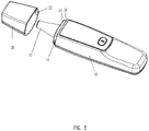
- FIG. 1 to FIG. 3 there is shown a specific structure of an embodiment of the present invention.
- An infrared thermometer capable of switching a forehead temperature measurement mode and an ear temperature measurement mode comprises an infrared thermometer body 10 and a forehead temperature measurement cover 20.
- the infrared thermometer body 10 is provided with a power switch, a display screen, and the like.
- the infrared thermometer body 10 has a measuring probe 11.
- the infrared thermometer body 10 includes a printed circuit board 12 therein.
- the measuring probe 11 is connected to the printed circuit board 12.
- the printed circuit board 12 is connected with a first electrical contact 17.
- the forehead temperature measurement cover 20 has a thermistor 21 and a second electrical contact 23 connected to the thermistor 21.
- the forehead temperature measurement cover 20 is detachably connected to the infrared thermometer body 10 to selectively cover or expose the measuring probe 11 for switching the forehead temperature measurement mode and the ear temperature measurement mode.
- the second electrical contact 23 and the first electrical contact 17 form an electrical connection so that the thermistor 21 is connected to the printed circuit board 12.
- the second electrical contact 23 and the first electrical contact 17 form the electrical connection so that the thermistor 21 is connected to the printed circuit board 12, and the printed circuit board 12 determines that the forehead temperature measurement mode is performed to obtain a forehead temperature value; and the printed circuit board 12 acquires the resistance value of the thermistor 21 to calculate and obtain the ambient temperature and compensates the forehead temperature value measured by the infrared thermometer body 10 by using the ambient temperature to obtain a calibrated forehead temperature value.
- the measuring probe 11 is exposed, the printed circuit board 12 is not connected with the thermistor 21, and the printed circuit board 12 determines that the ear temperature measurement mode is performed.
- the forehead temperature measurement mode or the ear temperature measurement mode is determined by whether the thermistor 21 is connected to the printed circuit board 12.
- the printed circuit board 12 is connected with a main control unit 13 for switching the corresponding forehead temperature measurement mode and the ear temperature measurement mode automatically. There is no need to control the switch manually, without relying on a complex mechanical structure.
- the present invention improves the convenience and reliability of switching effectively.
- the forehead temperature measurement cover 20 is connected to the infrared thermometer body 10 in a pluggable manner.
- the mechanical connection of the forehead temperature measurement cover 20 and the infrared thermometer body 10 and the electrical connection of the first and second electrical contacts 17, 23 are completed by one insertion operation.
- the pluggable structure between the forehead temperature measurement cover 20 and the infrared thermometer body 10 may be implemented in different manners.
- a feasible structure is provided for explanation.
- One of the infrared thermometer body 10 and the forehead temperature measurement cover 20 has an engaging protrusion 14, and the other has an engaging recess 22.
- the first electrical contact 17 and the second electrical contact 23 are disposed on the engaging protrusion 14 and the engaging recess 22, respectively.
- the electrical connection between the first electrical contact 17 and the second electrical contact 23 is realized while the infrared thermometer body 10 and the forehead temperature measurement cover 20 are positioned mechanically.
- the first electrical contact and the second electrical contact may be disposed at other positions, not limited to the positions of the engaging protrusion 14 and the engaging recess 22.
- the electrical contacts may be a resilient boss to provide better and reliable contact between the first electrical contact and the second electrical contact.
- the infrared thermometer body 10 is provided with an annular raised platform 15 corresponding to the rear end of the measuring probe 11.
- the infrared thermometer body 10 has an annular groove 16 around the outer circumference of the annular raised platform 15.
- the engaging protrusion 14 is exposed in the annular groove 16.
- the engaging recess 22 is formed on the inner wall of the forehead temperature measurement cover 20.
- the forehead temperature measurement cover 20 is fitted to the annular groove 16.
- the forehead temperature measurement cover is provided with the thermistor.
- the thermistor is used as the detecting component for switching the forehead temperature measurement mode and the ear temperature measurement mode.
- the thermistor is used as the component for detecting the ambient temperature.
- the ambient temperature is fed back to compensate the forehead temperature value measured by the infrared thermometer body, thereby obtaining the calibrated forehead temperature value and improving the accuracy of the forehead temperature measurement.
Landscapes
- Physics & Mathematics (AREA)
- General Physics & Mathematics (AREA)
- Health & Medical Sciences (AREA)
- Spectroscopy & Molecular Physics (AREA)
- Life Sciences & Earth Sciences (AREA)
- Medical Informatics (AREA)
- Surgery (AREA)
- Engineering & Computer Science (AREA)
- Biomedical Technology (AREA)
- Heart & Thoracic Surgery (AREA)
- Biophysics (AREA)
- Molecular Biology (AREA)
- Pathology (AREA)
- Animal Behavior & Ethology (AREA)
- General Health & Medical Sciences (AREA)
- Public Health (AREA)
- Veterinary Medicine (AREA)
- Otolaryngology (AREA)
- Measuring And Recording Apparatus For Diagnosis (AREA)
- Radiation Pyrometers (AREA)
Claims (6)
- Infrarotthermometer, das in der Lage ist, zwischen einem Stirntemperatur-Messmodus und einem Ohrtemperatur-Messmodus umzuschalten, einen Infrarotthermometer-Hauptteil (10) und eine Abdeckung (20) für die Stirntemperaturmessung umfassend, wobei:ein Ende des Infrarotthermometer-Hauptteils (10) eine Messsonde (11) aufweist, der Infrarotthermometer-Hauptteil (10) eine Leiterplatte (12) darin beinhaltet, die Messsonde (11) mit der Leiterplatte (12) verbunden ist, die Abdeckung (20) für die Stirntemperaturmessung lösbar mit dem Infrarotthermometer-Hauptteil (10) verbunden ist, um die Messsonde (11) wahlweise abzudecken oder freizulegen, um zwischen dem Stirntemperatur-Messmodus und dem Ohrtemperatur-Messmodus umzuschalten,die Leiterplatte (12) mit einem ersten elektrischen Kontakt (17) verbunden ist,dadurch gekennzeichnet, dass:die Abdeckung (20) für die Stirntemperaturmessung einen Thermistor (21) und einem zweiten elektrischen Kontakt (23) aufweist, welcher mit dem Thermistor (21) verbunden ist, undder zweite elektrische Kontakt (23) und der erste elektrische Kontakt (17) eine elektrische Verbindung bilden, wenn die Abdeckung (20) für die Stirntemperaturmessung mit dem Infrarotthermometer-Hauptteil (10) verbunden ist, so dass der Thermistor (21) mit der Leiterplatte (12) verbunden ist und das Thermometer in einen Stirntemperatur-Messmodus schaltet, sobald der Thermistor (21) mit der Leiterplatte (12) verbunden ist.
- Infrarotthermometer nach Anspruch 1, wobei eines von dem Infrarotthermometer-Hauptteil (10) und der Abdeckung (20) für die Stirntemperaturmessung einen Eingriffsvorsprung (14) aufweist und das andere eine Eingriffsvertiefung (22) aufweist, wobei durch den in die Eingriffsvertiefung (22) eingesetzten Eingriffsvorsprung (14) die Abdeckung (20) für die Stirntemperaturmessung und der Infrarotthermometer-Hauptteil (10) miteinander verbunden und positioniert sind.
- Infrarotthermometer nach Anspruch 2, wobei der erste elektrische Kontakt (17) und der zweite elektrische Kontakt (23) an dem Eingriffsvorsprung (14) beziehungsweise der Eingriffsvertiefung (22) angeordnet sind, wobei die elektrische Verbindung zwischen dem ersten elektrischen Kontakt (17) und dem zweiten elektrischen Kontakt (23) realisiert ist, während der Infrarotthermometer-Hauptteil (10) und die Abdeckung (20) für die Stirntemperaturmessung mechanisch positioniert worden sind.
- Infrarotthermometer nach Anspruch 3, wobei der Infrarotthermometer-Hauptteil (10) mit einem ringförmigen erhöhten Absatz (15) versehen ist, der einem hinteren Ende der Messsonde (11) entspricht, wobei der Infrarotthermometer-Hauptteil (10) rings um einen Außenumfang des ringförmigen erhöhten Absatzes (15) eine ringförmige Auskehlung (16) aufweist, wobei der Eingriffsvorsprung (14) in der ringförmigen Auskehlung (16) freiliegt, die Eingriffsvertiefung (22) an einer inneren Wandung der Abdeckung (20) für die Stirntemperaturmessung gebildet ist und die Abdeckung (20) für die Stirntemperaturmessung auf die ringförmige Auskehlung (16) aufgesetzt ist.
- Verfahren zum Umschalten zwischen einem Stirntemperatur-Messmodus und einem Ohrtemperatur-Messmodus in dem Infrarotthermometer nach Anspruch 1, dadurch gekennzeichnet, dass:der zweite elektrische Kontakt (23) und der erste elektrische Kontakt (17) die elektrische Verbindung bilden, wenn die Abdeckung (20) für die Stirntemperaturmessung mit dem Infrarotthermometer-Hauptteil (10) verbunden wird, so dass der Thermistor (21) mit der Leiterplatte (12) verbunden wird und die Leiterplatte (12) durch das Bestimmen, dass der Thermistor (21) mit der Leiterplatte (12) verbunden ist, bestimmt, dass der Stirntemperatur-Messmodus ausgeführt wird, um einen Stirntemperaturwert zu erzielen, und die Leiterplatte (12) einen Widerstandswert des Thermistors (21) erfasst, um eine Umgebungstemperatur zu berechnen und zu erzielen, und den Stirntemperaturwert, der durch den Infrarotthermometer-Hauptteil (10) gemessen wird, mit Hilfe der Umgebungstemperatur kompensiert, um einen kalibrierten Stirntemperaturwert zu erzielen,die Leiterplatte (12) nicht mit dem Thermistor (21) verbunden ist, wenn die Abdeckung (20) für die Stirntemperaturmessung nicht mit dem Infrarotthermometer-Hauptteil (10) verbunden ist, die Messsonde (11) freiliegt, und die Leiterplatte (12) bestimmt, dass der Ohrtemperatur-Messmodus ausgeführt wird.
- Verfahren nach Anspruch 5, wobei die Abdeckung (20) für die Stirntemperaturmessung mit dem Infrarotthermometer-Hauptteil (10) in einer steckbaren Weise verbunden wird, wenn die Abdeckung (20) für die Stirntemperaturmessung und der Infrarotthermometer-Hauptteil (10) mechanisch verbunden werden, wobei der erste elektrische Kontakt (17) und der zweite elektrische Kontakt (23) die elektrische Verbindung bilden.
Priority Applications (3)
| Application Number | Priority Date | Filing Date | Title |
|---|---|---|---|
| PT191591338T PT3699564T (pt) | 2019-02-25 | 2019-02-25 | Termômetro infravermelho capaz de comutar o modo da medição da temperatura da antena e o modo da medição da temperatura da orelha e o método de comutação |
| EP19159133.8A EP3699564B1 (de) | 2019-02-25 | 2019-02-25 | Infrarotthermometer mit fähigkeit zur umschaltung des stirntemperaturmessmodus und ohrtemperaturmessmodus und umschaltverfahren |
| RS20220615A RS63358B1 (sr) | 2019-02-25 | 2019-02-25 | Infracrveni termometar koji može da promeni režim merenja temperature čela i režim merenja temperature uha i postupak promene |
Applications Claiming Priority (1)
| Application Number | Priority Date | Filing Date | Title |
|---|---|---|---|
| EP19159133.8A EP3699564B1 (de) | 2019-02-25 | 2019-02-25 | Infrarotthermometer mit fähigkeit zur umschaltung des stirntemperaturmessmodus und ohrtemperaturmessmodus und umschaltverfahren |
Publications (2)
| Publication Number | Publication Date |
|---|---|
| EP3699564A1 EP3699564A1 (de) | 2020-08-26 |
| EP3699564B1 true EP3699564B1 (de) | 2022-04-06 |
Family
ID=65576225
Family Applications (1)
| Application Number | Title | Priority Date | Filing Date |
|---|---|---|---|
| EP19159133.8A Active EP3699564B1 (de) | 2019-02-25 | 2019-02-25 | Infrarotthermometer mit fähigkeit zur umschaltung des stirntemperaturmessmodus und ohrtemperaturmessmodus und umschaltverfahren |
Country Status (3)
| Country | Link |
|---|---|
| EP (1) | EP3699564B1 (de) |
| PT (1) | PT3699564T (de) |
| RS (1) | RS63358B1 (de) |
Families Citing this family (1)
| Publication number | Priority date | Publication date | Assignee | Title |
|---|---|---|---|---|
| CN112097915B (zh) * | 2020-09-10 | 2022-07-26 | 江西省桑格尔电子有限公司 | 一种人脸识别测温方法及装置 |
Family Cites Families (3)
| Publication number | Priority date | Publication date | Assignee | Title |
|---|---|---|---|---|
| US20040047392A1 (en) * | 2002-09-06 | 2004-03-11 | Shu-Mei Wu | Apparatus for measuring ear and forehead temperature |
| CN203745084U (zh) * | 2013-12-25 | 2014-07-30 | 深圳市美的连电子科技有限公司 | 一种红外测温装置 |
| CN207866369U (zh) * | 2018-02-08 | 2018-09-14 | 东莞市医脉实业有限公司 | 一种磁感应识别探头帽盖的红外温度计 |
-
2019
- 2019-02-25 EP EP19159133.8A patent/EP3699564B1/de active Active
- 2019-02-25 PT PT191591338T patent/PT3699564T/pt unknown
- 2019-02-25 RS RS20220615A patent/RS63358B1/sr unknown
Also Published As
| Publication number | Publication date |
|---|---|
| RS63358B1 (sr) | 2022-07-29 |
| PT3699564T (pt) | 2022-05-05 |
| EP3699564A1 (de) | 2020-08-26 |
Similar Documents
| Publication | Publication Date | Title |
|---|---|---|
| US11105683B2 (en) | Infrared thermometer capable of switching forehead temperature measurement mode and ear temperature measurement mode and switching method | |
| US20230213392A1 (en) | Single-pin wireless electronic thermometer and charging device for the same | |
| CN113758597B (zh) | 温度探针和烤箱组件 | |
| CN109540301B (zh) | 额耳测温模式切换的红外测温仪及切换方法 | |
| TWI487890B (zh) | An ear thermometer with ear canal sensing device | |
| JPH0741026B2 (ja) | 体温計 | |
| US20020163955A1 (en) | Detachable probe mounting arrangement for an electronic clinical thermometer | |
| US20010021218A1 (en) | Clinical thermometer for receiving infrared radiation from a human eardrum | |
| CN114010072A (zh) | 烤箱的温度控制方法及烤箱 | |
| US20250327707A1 (en) | Wireless food temperature detector for oven | |
| US20250137851A1 (en) | Bluetooth food thermometer and assembly thereof | |
| US20040047392A1 (en) | Apparatus for measuring ear and forehead temperature | |
| US8500327B2 (en) | Safety thermometer | |
| EP3699564A1 (de) | Infrarotthermometer mit fähigkeit zur umschaltung des stirntemperaturmessmodus und ohrtemperaturmessmodus und umschaltverfahren | |
| US6935777B2 (en) | Electronic thermometer with a directionally adjustable LCD display | |
| CN209326793U (zh) | 额耳测温模式切换的红外测温仪 | |
| CN218647047U (zh) | 一种脉宽控制背光亮暗与蜂鸣声大小数字万用表 | |
| CN210442004U (zh) | 一种儿科环臂式体温计 | |
| US12422306B1 (en) | Sensor multifunctional Bluetooth food probe | |
| CN222528785U (zh) | 插入式温度探针 | |
| CN216143532U (zh) | 一种穿戴设备及其底壳组件 | |
| CN215931126U (zh) | 一种食品温度计 | |
| CN111998970A (zh) | 一种用于断路器的温度测量装置 | |
| EP4686925A1 (de) | Temperaturmessvorrichtung | |
| CN205411158U (zh) | 一种电子体温计 |
Legal Events
| Date | Code | Title | Description |
|---|---|---|---|
| PUAI | Public reference made under article 153(3) epc to a published international application that has entered the european phase |
Free format text: ORIGINAL CODE: 0009012 |
|
| STAA | Information on the status of an ep patent application or granted ep patent |
Free format text: STATUS: REQUEST FOR EXAMINATION WAS MADE |
|
| 17P | Request for examination filed |
Effective date: 20190611 |
|
| AK | Designated contracting states |
Kind code of ref document: A1 Designated state(s): AL AT BE BG CH CY CZ DE DK EE ES FI FR GB GR HR HU IE IS IT LI LT LU LV MC MK MT NL NO PL PT RO RS SE SI SK SM TR |
|
| AX | Request for extension of the european patent |
Extension state: BA ME |
|
| GRAP | Despatch of communication of intention to grant a patent |
Free format text: ORIGINAL CODE: EPIDOSNIGR1 |
|
| STAA | Information on the status of an ep patent application or granted ep patent |
Free format text: STATUS: GRANT OF PATENT IS INTENDED |
|
| RIC1 | Information provided on ipc code assigned before grant |
Ipc: G01K 13/00 20210101ALI20210824BHEP Ipc: A61B 5/01 20060101ALI20210824BHEP Ipc: G01J 5/06 20060101ALI20210824BHEP Ipc: G01J 5/00 20060101ALI20210824BHEP Ipc: G01J 5/20 20060101ALI20210824BHEP Ipc: G01J 5/02 20060101AFI20210824BHEP |
|
| INTG | Intention to grant announced |
Effective date: 20210924 |
|
| GRAS | Grant fee paid |
Free format text: ORIGINAL CODE: EPIDOSNIGR3 |
|
| GRAA | (expected) grant |
Free format text: ORIGINAL CODE: 0009210 |
|
| STAA | Information on the status of an ep patent application or granted ep patent |
Free format text: STATUS: THE PATENT HAS BEEN GRANTED |
|
| AK | Designated contracting states |
Kind code of ref document: B1 Designated state(s): AL AT BE BG CH CY CZ DE DK EE ES FI FR GB GR HR HU IE IS IT LI LT LU LV MC MK MT NL NO PL PT RO RS SE SI SK SM TR |
|
| REG | Reference to a national code |
Ref country code: GB Ref legal event code: FG4D |
|
| REG | Reference to a national code |
Ref country code: CH Ref legal event code: EP |
|
| REG | Reference to a national code |
Ref country code: AT Ref legal event code: REF Ref document number: 1481761 Country of ref document: AT Kind code of ref document: T Effective date: 20220415 |
|
| REG | Reference to a national code |
Ref country code: DE Ref legal event code: R096 Ref document number: 602019013251 Country of ref document: DE |
|
| REG | Reference to a national code |
Ref country code: IE Ref legal event code: FG4D |
|
| REG | Reference to a national code |
Ref country code: FI Ref legal event code: FGE |
|
| REG | Reference to a national code |
Ref country code: PT Ref legal event code: SC4A Ref document number: 3699564 Country of ref document: PT Date of ref document: 20220505 Kind code of ref document: T Free format text: AVAILABILITY OF NATIONAL TRANSLATION Effective date: 20220427 |
|
| REG | Reference to a national code |
Ref country code: SE Ref legal event code: TRGR |
|
| REG | Reference to a national code |
Ref country code: NL Ref legal event code: FP |
|
| REG | Reference to a national code |
Ref country code: LT Ref legal event code: MG9D |
|
| REG | Reference to a national code |
Ref country code: HU Ref legal event code: AG4A Ref document number: E058519 Country of ref document: HU |
|
| REG | Reference to a national code |
Ref country code: AT Ref legal event code: MK05 Ref document number: 1481761 Country of ref document: AT Kind code of ref document: T Effective date: 20220406 |
|
| PG25 | Lapsed in a contracting state [announced via postgrant information from national office to epo] |
Ref country code: NO Free format text: LAPSE BECAUSE OF FAILURE TO SUBMIT A TRANSLATION OF THE DESCRIPTION OR TO PAY THE FEE WITHIN THE PRESCRIBED TIME-LIMIT Effective date: 20220706 Ref country code: LT Free format text: LAPSE BECAUSE OF FAILURE TO SUBMIT A TRANSLATION OF THE DESCRIPTION OR TO PAY THE FEE WITHIN THE PRESCRIBED TIME-LIMIT Effective date: 20220406 Ref country code: HR Free format text: LAPSE BECAUSE OF FAILURE TO SUBMIT A TRANSLATION OF THE DESCRIPTION OR TO PAY THE FEE WITHIN THE PRESCRIBED TIME-LIMIT Effective date: 20220406 Ref country code: GR Free format text: LAPSE BECAUSE OF FAILURE TO SUBMIT A TRANSLATION OF THE DESCRIPTION OR TO PAY THE FEE WITHIN THE PRESCRIBED TIME-LIMIT Effective date: 20220707 Ref country code: ES Free format text: LAPSE BECAUSE OF FAILURE TO SUBMIT A TRANSLATION OF THE DESCRIPTION OR TO PAY THE FEE WITHIN THE PRESCRIBED TIME-LIMIT Effective date: 20220406 Ref country code: BG Free format text: LAPSE BECAUSE OF FAILURE TO SUBMIT A TRANSLATION OF THE DESCRIPTION OR TO PAY THE FEE WITHIN THE PRESCRIBED TIME-LIMIT Effective date: 20220706 Ref country code: AT Free format text: LAPSE BECAUSE OF FAILURE TO SUBMIT A TRANSLATION OF THE DESCRIPTION OR TO PAY THE FEE WITHIN THE PRESCRIBED TIME-LIMIT Effective date: 20220406 |
|
| PG25 | Lapsed in a contracting state [announced via postgrant information from national office to epo] |
Ref country code: PL Free format text: LAPSE BECAUSE OF FAILURE TO SUBMIT A TRANSLATION OF THE DESCRIPTION OR TO PAY THE FEE WITHIN THE PRESCRIBED TIME-LIMIT Effective date: 20220406 Ref country code: LV Free format text: LAPSE BECAUSE OF FAILURE TO SUBMIT A TRANSLATION OF THE DESCRIPTION OR TO PAY THE FEE WITHIN THE PRESCRIBED TIME-LIMIT Effective date: 20220406 Ref country code: IS Free format text: LAPSE BECAUSE OF FAILURE TO SUBMIT A TRANSLATION OF THE DESCRIPTION OR TO PAY THE FEE WITHIN THE PRESCRIBED TIME-LIMIT Effective date: 20220806 |
|
| REG | Reference to a national code |
Ref country code: DE Ref legal event code: R097 Ref document number: 602019013251 Country of ref document: DE |
|
| PG25 | Lapsed in a contracting state [announced via postgrant information from national office to epo] |
Ref country code: SM Free format text: LAPSE BECAUSE OF FAILURE TO SUBMIT A TRANSLATION OF THE DESCRIPTION OR TO PAY THE FEE WITHIN THE PRESCRIBED TIME-LIMIT Effective date: 20220406 Ref country code: SK Free format text: LAPSE BECAUSE OF FAILURE TO SUBMIT A TRANSLATION OF THE DESCRIPTION OR TO PAY THE FEE WITHIN THE PRESCRIBED TIME-LIMIT Effective date: 20220406 Ref country code: RO Free format text: LAPSE BECAUSE OF FAILURE TO SUBMIT A TRANSLATION OF THE DESCRIPTION OR TO PAY THE FEE WITHIN THE PRESCRIBED TIME-LIMIT Effective date: 20220406 Ref country code: EE Free format text: LAPSE BECAUSE OF FAILURE TO SUBMIT A TRANSLATION OF THE DESCRIPTION OR TO PAY THE FEE WITHIN THE PRESCRIBED TIME-LIMIT Effective date: 20220406 Ref country code: DK Free format text: LAPSE BECAUSE OF FAILURE TO SUBMIT A TRANSLATION OF THE DESCRIPTION OR TO PAY THE FEE WITHIN THE PRESCRIBED TIME-LIMIT Effective date: 20220406 Ref country code: CZ Free format text: LAPSE BECAUSE OF FAILURE TO SUBMIT A TRANSLATION OF THE DESCRIPTION OR TO PAY THE FEE WITHIN THE PRESCRIBED TIME-LIMIT Effective date: 20220406 |
|
| PLBE | No opposition filed within time limit |
Free format text: ORIGINAL CODE: 0009261 |
|
| STAA | Information on the status of an ep patent application or granted ep patent |
Free format text: STATUS: NO OPPOSITION FILED WITHIN TIME LIMIT |
|
| 26N | No opposition filed |
Effective date: 20230110 |
|
| PG25 | Lapsed in a contracting state [announced via postgrant information from national office to epo] |
Ref country code: AL Free format text: LAPSE BECAUSE OF FAILURE TO SUBMIT A TRANSLATION OF THE DESCRIPTION OR TO PAY THE FEE WITHIN THE PRESCRIBED TIME-LIMIT Effective date: 20220406 |
|
| PG25 | Lapsed in a contracting state [announced via postgrant information from national office to epo] |
Ref country code: SI Free format text: LAPSE BECAUSE OF FAILURE TO SUBMIT A TRANSLATION OF THE DESCRIPTION OR TO PAY THE FEE WITHIN THE PRESCRIBED TIME-LIMIT Effective date: 20220406 |
|
| PG25 | Lapsed in a contracting state [announced via postgrant information from national office to epo] |
Ref country code: MC Free format text: LAPSE BECAUSE OF FAILURE TO SUBMIT A TRANSLATION OF THE DESCRIPTION OR TO PAY THE FEE WITHIN THE PRESCRIBED TIME-LIMIT Effective date: 20220406 |
|
| REG | Reference to a national code |
Ref country code: CH Ref legal event code: PL |
|
| REG | Reference to a national code |
Ref country code: SE Ref legal event code: EUG |
|
| REG | Reference to a national code |
Ref country code: BE Ref legal event code: MM Effective date: 20230228 |
|
| PG25 | Lapsed in a contracting state [announced via postgrant information from national office to epo] |
Ref country code: SE Free format text: LAPSE BECAUSE OF NON-PAYMENT OF DUE FEES Effective date: 20230226 Ref country code: LU Free format text: LAPSE BECAUSE OF NON-PAYMENT OF DUE FEES Effective date: 20230225 Ref country code: LI Free format text: LAPSE BECAUSE OF NON-PAYMENT OF DUE FEES Effective date: 20230228 Ref country code: FI Free format text: LAPSE BECAUSE OF NON-PAYMENT OF DUE FEES Effective date: 20230225 Ref country code: CH Free format text: LAPSE BECAUSE OF NON-PAYMENT OF DUE FEES Effective date: 20230228 |
|
| PG25 | Lapsed in a contracting state [announced via postgrant information from national office to epo] |
Ref country code: RS Free format text: LAPSE BECAUSE OF NON-PAYMENT OF DUE FEES Effective date: 20230831 Ref country code: HU Free format text: LAPSE BECAUSE OF NON-PAYMENT OF DUE FEES Effective date: 20230226 |
|
| REG | Reference to a national code |
Ref country code: IE Ref legal event code: MM4A |
|
| PG25 | Lapsed in a contracting state [announced via postgrant information from national office to epo] |
Ref country code: IE Free format text: LAPSE BECAUSE OF NON-PAYMENT OF DUE FEES Effective date: 20230225 |
|
| PG25 | Lapsed in a contracting state [announced via postgrant information from national office to epo] |
Ref country code: BE Free format text: LAPSE BECAUSE OF NON-PAYMENT OF DUE FEES Effective date: 20230228 |
|
| PG25 | Lapsed in a contracting state [announced via postgrant information from national office to epo] |
Ref country code: BG Free format text: LAPSE BECAUSE OF FAILURE TO SUBMIT A TRANSLATION OF THE DESCRIPTION OR TO PAY THE FEE WITHIN THE PRESCRIBED TIME-LIMIT Effective date: 20220406 |
|
| PG25 | Lapsed in a contracting state [announced via postgrant information from national office to epo] |
Ref country code: BG Free format text: LAPSE BECAUSE OF FAILURE TO SUBMIT A TRANSLATION OF THE DESCRIPTION OR TO PAY THE FEE WITHIN THE PRESCRIBED TIME-LIMIT Effective date: 20220406 |
|
| PG25 | Lapsed in a contracting state [announced via postgrant information from national office to epo] |
Ref country code: CY Free format text: LAPSE BECAUSE OF FAILURE TO SUBMIT A TRANSLATION OF THE DESCRIPTION OR TO PAY THE FEE WITHIN THE PRESCRIBED TIME-LIMIT; INVALID AB INITIO Effective date: 20190225 |
|
| PGFP | Annual fee paid to national office [announced via postgrant information from national office to epo] |
Ref country code: NL Payment date: 20260209 Year of fee payment: 8 |
|
| PGFP | Annual fee paid to national office [announced via postgrant information from national office to epo] |
Ref country code: GB Payment date: 20260209 Year of fee payment: 8 |
|
| PGFP | Annual fee paid to national office [announced via postgrant information from national office to epo] |
Ref country code: DE Payment date: 20260217 Year of fee payment: 8 |
|
| PGFP | Annual fee paid to national office [announced via postgrant information from national office to epo] |
Ref country code: IT Payment date: 20260227 Year of fee payment: 8 |
|
| PGFP | Annual fee paid to national office [announced via postgrant information from national office to epo] |
Ref country code: FR Payment date: 20260209 Year of fee payment: 8 |
|
| PGFP | Annual fee paid to national office [announced via postgrant information from national office to epo] |
Ref country code: PT Payment date: 20260206 Year of fee payment: 8 |