EP3699476A1 - Double shell tank, and ship - Google Patents
Double shell tank, and ship Download PDFInfo
- Publication number
- EP3699476A1 EP3699476A1 EP18868420.3A EP18868420A EP3699476A1 EP 3699476 A1 EP3699476 A1 EP 3699476A1 EP 18868420 A EP18868420 A EP 18868420A EP 3699476 A1 EP3699476 A1 EP 3699476A1
- Authority
- EP
- European Patent Office
- Prior art keywords
- inner shell
- shell
- metal sheet
- adsorbent
- double
- Prior art date
- Legal status (The legal status is an assumption and is not a legal conclusion. Google has not performed a legal analysis and makes no representation as to the accuracy of the status listed.)
- Granted
Links
Images




Classifications
-
- F—MECHANICAL ENGINEERING; LIGHTING; HEATING; WEAPONS; BLASTING
- F17—STORING OR DISTRIBUTING GASES OR LIQUIDS
- F17C—VESSELS FOR CONTAINING OR STORING COMPRESSED, LIQUEFIED OR SOLIDIFIED GASES; FIXED-CAPACITY GAS-HOLDERS; FILLING VESSELS WITH, OR DISCHARGING FROM VESSELS, COMPRESSED, LIQUEFIED, OR SOLIDIFIED GASES
- F17C3/00—Vessels not under pressure
- F17C3/02—Vessels not under pressure with provision for thermal insulation
- F17C3/04—Vessels not under pressure with provision for thermal insulation by insulating layers
-
- B—PERFORMING OPERATIONS; TRANSPORTING
- B63—SHIPS OR OTHER WATERBORNE VESSELS; RELATED EQUIPMENT
- B63B—SHIPS OR OTHER WATERBORNE VESSELS; EQUIPMENT FOR SHIPPING
- B63B25/00—Load-accommodating arrangements, e.g. stowing, trimming; Vessels characterised thereby
- B63B25/02—Load-accommodating arrangements, e.g. stowing, trimming; Vessels characterised thereby for bulk goods
- B63B25/08—Load-accommodating arrangements, e.g. stowing, trimming; Vessels characterised thereby for bulk goods fluid
- B63B25/12—Load-accommodating arrangements, e.g. stowing, trimming; Vessels characterised thereby for bulk goods fluid closed
- B63B25/16—Load-accommodating arrangements, e.g. stowing, trimming; Vessels characterised thereby for bulk goods fluid closed heat-insulated
-
- B—PERFORMING OPERATIONS; TRANSPORTING
- B63—SHIPS OR OTHER WATERBORNE VESSELS; RELATED EQUIPMENT
- B63B—SHIPS OR OTHER WATERBORNE VESSELS; EQUIPMENT FOR SHIPPING
- B63B25/00—Load-accommodating arrangements, e.g. stowing, trimming; Vessels characterised thereby
- B63B25/02—Load-accommodating arrangements, e.g. stowing, trimming; Vessels characterised thereby for bulk goods
- B63B25/08—Load-accommodating arrangements, e.g. stowing, trimming; Vessels characterised thereby for bulk goods fluid
-
- B—PERFORMING OPERATIONS; TRANSPORTING
- B63—SHIPS OR OTHER WATERBORNE VESSELS; RELATED EQUIPMENT
- B63B—SHIPS OR OTHER WATERBORNE VESSELS; EQUIPMENT FOR SHIPPING
- B63B73/00—Building or assembling vessels or marine structures, e.g. hulls or offshore platforms
- B63B73/40—Building or assembling vessels or marine structures, e.g. hulls or offshore platforms characterised by joining methods
- B63B73/49—Building or assembling vessels or marine structures, e.g. hulls or offshore platforms characterised by joining methods by means of threaded members, e.g. screws, threaded bolts or nuts
-
- B—PERFORMING OPERATIONS; TRANSPORTING
- B65—CONVEYING; PACKING; STORING; HANDLING THIN OR FILAMENTARY MATERIAL
- B65D—CONTAINERS FOR STORAGE OR TRANSPORT OF ARTICLES OR MATERIALS, e.g. BAGS, BARRELS, BOTTLES, BOXES, CANS, CARTONS, CRATES, DRUMS, JARS, TANKS, HOPPERS, FORWARDING CONTAINERS; ACCESSORIES, CLOSURES, OR FITTINGS THEREFOR; PACKAGING ELEMENTS; PACKAGES
- B65D90/00—Component parts, details or accessories for large containers
- B65D90/02—Wall construction
- B65D90/06—Coverings, e.g. for insulating purposes
-
- F—MECHANICAL ENGINEERING; LIGHTING; HEATING; WEAPONS; BLASTING
- F17—STORING OR DISTRIBUTING GASES OR LIQUIDS
- F17C—VESSELS FOR CONTAINING OR STORING COMPRESSED, LIQUEFIED OR SOLIDIFIED GASES; FIXED-CAPACITY GAS-HOLDERS; FILLING VESSELS WITH, OR DISCHARGING FROM VESSELS, COMPRESSED, LIQUEFIED, OR SOLIDIFIED GASES
- F17C11/00—Use of gas-solvents or gas-sorbents in vessels
-
- F—MECHANICAL ENGINEERING; LIGHTING; HEATING; WEAPONS; BLASTING
- F17—STORING OR DISTRIBUTING GASES OR LIQUIDS
- F17C—VESSELS FOR CONTAINING OR STORING COMPRESSED, LIQUEFIED OR SOLIDIFIED GASES; FIXED-CAPACITY GAS-HOLDERS; FILLING VESSELS WITH, OR DISCHARGING FROM VESSELS, COMPRESSED, LIQUEFIED, OR SOLIDIFIED GASES
- F17C3/00—Vessels not under pressure
- F17C3/02—Vessels not under pressure with provision for thermal insulation
- F17C3/025—Bulk storage in barges or on ships
-
- F—MECHANICAL ENGINEERING; LIGHTING; HEATING; WEAPONS; BLASTING
- F17—STORING OR DISTRIBUTING GASES OR LIQUIDS
- F17C—VESSELS FOR CONTAINING OR STORING COMPRESSED, LIQUEFIED OR SOLIDIFIED GASES; FIXED-CAPACITY GAS-HOLDERS; FILLING VESSELS WITH, OR DISCHARGING FROM VESSELS, COMPRESSED, LIQUEFIED, OR SOLIDIFIED GASES
- F17C3/00—Vessels not under pressure
- F17C3/02—Vessels not under pressure with provision for thermal insulation
- F17C3/08—Vessels not under pressure with provision for thermal insulation by vacuum spaces, e.g. Dewar flask
-
- B—PERFORMING OPERATIONS; TRANSPORTING
- B63—SHIPS OR OTHER WATERBORNE VESSELS; RELATED EQUIPMENT
- B63B—SHIPS OR OTHER WATERBORNE VESSELS; EQUIPMENT FOR SHIPPING
- B63B2231/00—Material used for some parts or elements, or for particular purposes
- B63B2231/02—Metallic materials
-
- F—MECHANICAL ENGINEERING; LIGHTING; HEATING; WEAPONS; BLASTING
- F17—STORING OR DISTRIBUTING GASES OR LIQUIDS
- F17C—VESSELS FOR CONTAINING OR STORING COMPRESSED, LIQUEFIED OR SOLIDIFIED GASES; FIXED-CAPACITY GAS-HOLDERS; FILLING VESSELS WITH, OR DISCHARGING FROM VESSELS, COMPRESSED, LIQUEFIED, OR SOLIDIFIED GASES
- F17C2201/00—Vessel construction, in particular geometry, arrangement or size
- F17C2201/01—Shape
- F17C2201/0104—Shape cylindrical
- F17C2201/0109—Shape cylindrical with exteriorly curved end-piece
-
- F—MECHANICAL ENGINEERING; LIGHTING; HEATING; WEAPONS; BLASTING
- F17—STORING OR DISTRIBUTING GASES OR LIQUIDS
- F17C—VESSELS FOR CONTAINING OR STORING COMPRESSED, LIQUEFIED OR SOLIDIFIED GASES; FIXED-CAPACITY GAS-HOLDERS; FILLING VESSELS WITH, OR DISCHARGING FROM VESSELS, COMPRESSED, LIQUEFIED, OR SOLIDIFIED GASES
- F17C2201/00—Vessel construction, in particular geometry, arrangement or size
- F17C2201/03—Orientation
- F17C2201/035—Orientation with substantially horizontal main axis
-
- F—MECHANICAL ENGINEERING; LIGHTING; HEATING; WEAPONS; BLASTING
- F17—STORING OR DISTRIBUTING GASES OR LIQUIDS
- F17C—VESSELS FOR CONTAINING OR STORING COMPRESSED, LIQUEFIED OR SOLIDIFIED GASES; FIXED-CAPACITY GAS-HOLDERS; FILLING VESSELS WITH, OR DISCHARGING FROM VESSELS, COMPRESSED, LIQUEFIED, OR SOLIDIFIED GASES
- F17C2203/00—Vessel construction, in particular walls or details thereof
- F17C2203/03—Thermal insulations
- F17C2203/0391—Thermal insulations by vacuum
-
- F—MECHANICAL ENGINEERING; LIGHTING; HEATING; WEAPONS; BLASTING
- F17—STORING OR DISTRIBUTING GASES OR LIQUIDS
- F17C—VESSELS FOR CONTAINING OR STORING COMPRESSED, LIQUEFIED OR SOLIDIFIED GASES; FIXED-CAPACITY GAS-HOLDERS; FILLING VESSELS WITH, OR DISCHARGING FROM VESSELS, COMPRESSED, LIQUEFIED, OR SOLIDIFIED GASES
- F17C2203/00—Vessel construction, in particular walls or details thereof
- F17C2203/03—Thermal insulations
- F17C2203/0391—Thermal insulations by vacuum
- F17C2203/0395—Getter
-
- F—MECHANICAL ENGINEERING; LIGHTING; HEATING; WEAPONS; BLASTING
- F17—STORING OR DISTRIBUTING GASES OR LIQUIDS
- F17C—VESSELS FOR CONTAINING OR STORING COMPRESSED, LIQUEFIED OR SOLIDIFIED GASES; FIXED-CAPACITY GAS-HOLDERS; FILLING VESSELS WITH, OR DISCHARGING FROM VESSELS, COMPRESSED, LIQUEFIED, OR SOLIDIFIED GASES
- F17C2203/00—Vessel construction, in particular walls or details thereof
- F17C2203/06—Materials for walls or layers thereof; Properties or structures of walls or their materials
- F17C2203/0602—Wall structures; Special features thereof
- F17C2203/0612—Wall structures
- F17C2203/0626—Multiple walls
- F17C2203/0629—Two walls
-
- F—MECHANICAL ENGINEERING; LIGHTING; HEATING; WEAPONS; BLASTING
- F17—STORING OR DISTRIBUTING GASES OR LIQUIDS
- F17C—VESSELS FOR CONTAINING OR STORING COMPRESSED, LIQUEFIED OR SOLIDIFIED GASES; FIXED-CAPACITY GAS-HOLDERS; FILLING VESSELS WITH, OR DISCHARGING FROM VESSELS, COMPRESSED, LIQUEFIED, OR SOLIDIFIED GASES
- F17C2203/00—Vessel construction, in particular walls or details thereof
- F17C2203/06—Materials for walls or layers thereof; Properties or structures of walls or their materials
- F17C2203/0634—Materials for walls or layers thereof
- F17C2203/0636—Metals
- F17C2203/0639—Steels
-
- F—MECHANICAL ENGINEERING; LIGHTING; HEATING; WEAPONS; BLASTING
- F17—STORING OR DISTRIBUTING GASES OR LIQUIDS
- F17C—VESSELS FOR CONTAINING OR STORING COMPRESSED, LIQUEFIED OR SOLIDIFIED GASES; FIXED-CAPACITY GAS-HOLDERS; FILLING VESSELS WITH, OR DISCHARGING FROM VESSELS, COMPRESSED, LIQUEFIED, OR SOLIDIFIED GASES
- F17C2209/00—Vessel construction, in particular methods of manufacturing
- F17C2209/22—Assembling processes
- F17C2209/228—Assembling processes by screws, bolts or rivets
-
- F—MECHANICAL ENGINEERING; LIGHTING; HEATING; WEAPONS; BLASTING
- F17—STORING OR DISTRIBUTING GASES OR LIQUIDS
- F17C—VESSELS FOR CONTAINING OR STORING COMPRESSED, LIQUEFIED OR SOLIDIFIED GASES; FIXED-CAPACITY GAS-HOLDERS; FILLING VESSELS WITH, OR DISCHARGING FROM VESSELS, COMPRESSED, LIQUEFIED, OR SOLIDIFIED GASES
- F17C2221/00—Handled fluid, in particular type of fluid
- F17C2221/01—Pure fluids
- F17C2221/012—Hydrogen
-
- F—MECHANICAL ENGINEERING; LIGHTING; HEATING; WEAPONS; BLASTING
- F17—STORING OR DISTRIBUTING GASES OR LIQUIDS
- F17C—VESSELS FOR CONTAINING OR STORING COMPRESSED, LIQUEFIED OR SOLIDIFIED GASES; FIXED-CAPACITY GAS-HOLDERS; FILLING VESSELS WITH, OR DISCHARGING FROM VESSELS, COMPRESSED, LIQUEFIED, OR SOLIDIFIED GASES
- F17C2221/00—Handled fluid, in particular type of fluid
- F17C2221/01—Pure fluids
- F17C2221/016—Noble gases (Ar, Kr, Xe)
- F17C2221/017—Helium
-
- F—MECHANICAL ENGINEERING; LIGHTING; HEATING; WEAPONS; BLASTING
- F17—STORING OR DISTRIBUTING GASES OR LIQUIDS
- F17C—VESSELS FOR CONTAINING OR STORING COMPRESSED, LIQUEFIED OR SOLIDIFIED GASES; FIXED-CAPACITY GAS-HOLDERS; FILLING VESSELS WITH, OR DISCHARGING FROM VESSELS, COMPRESSED, LIQUEFIED, OR SOLIDIFIED GASES
- F17C2221/00—Handled fluid, in particular type of fluid
- F17C2221/03—Mixtures
- F17C2221/032—Hydrocarbons
-
- F—MECHANICAL ENGINEERING; LIGHTING; HEATING; WEAPONS; BLASTING
- F17—STORING OR DISTRIBUTING GASES OR LIQUIDS
- F17C—VESSELS FOR CONTAINING OR STORING COMPRESSED, LIQUEFIED OR SOLIDIFIED GASES; FIXED-CAPACITY GAS-HOLDERS; FILLING VESSELS WITH, OR DISCHARGING FROM VESSELS, COMPRESSED, LIQUEFIED, OR SOLIDIFIED GASES
- F17C2221/00—Handled fluid, in particular type of fluid
- F17C2221/03—Mixtures
- F17C2221/032—Hydrocarbons
- F17C2221/033—Methane, e.g. natural gas, CNG, LNG, GNL, GNC, PLNG
-
- F—MECHANICAL ENGINEERING; LIGHTING; HEATING; WEAPONS; BLASTING
- F17—STORING OR DISTRIBUTING GASES OR LIQUIDS
- F17C—VESSELS FOR CONTAINING OR STORING COMPRESSED, LIQUEFIED OR SOLIDIFIED GASES; FIXED-CAPACITY GAS-HOLDERS; FILLING VESSELS WITH, OR DISCHARGING FROM VESSELS, COMPRESSED, LIQUEFIED, OR SOLIDIFIED GASES
- F17C2223/00—Handled fluid before transfer, i.e. state of fluid when stored in the vessel or before transfer from the vessel
- F17C2223/01—Handled fluid before transfer, i.e. state of fluid when stored in the vessel or before transfer from the vessel characterised by the phase
- F17C2223/0146—Two-phase
- F17C2223/0153—Liquefied gas, e.g. LPG, GPL
- F17C2223/0161—Liquefied gas, e.g. LPG, GPL cryogenic, e.g. LNG, GNL, PLNG
-
- F—MECHANICAL ENGINEERING; LIGHTING; HEATING; WEAPONS; BLASTING
- F17—STORING OR DISTRIBUTING GASES OR LIQUIDS
- F17C—VESSELS FOR CONTAINING OR STORING COMPRESSED, LIQUEFIED OR SOLIDIFIED GASES; FIXED-CAPACITY GAS-HOLDERS; FILLING VESSELS WITH, OR DISCHARGING FROM VESSELS, COMPRESSED, LIQUEFIED, OR SOLIDIFIED GASES
- F17C2223/00—Handled fluid before transfer, i.e. state of fluid when stored in the vessel or before transfer from the vessel
- F17C2223/03—Handled fluid before transfer, i.e. state of fluid when stored in the vessel or before transfer from the vessel characterised by the pressure level
- F17C2223/033—Small pressure, e.g. for liquefied gas
-
- F—MECHANICAL ENGINEERING; LIGHTING; HEATING; WEAPONS; BLASTING
- F17—STORING OR DISTRIBUTING GASES OR LIQUIDS
- F17C—VESSELS FOR CONTAINING OR STORING COMPRESSED, LIQUEFIED OR SOLIDIFIED GASES; FIXED-CAPACITY GAS-HOLDERS; FILLING VESSELS WITH, OR DISCHARGING FROM VESSELS, COMPRESSED, LIQUEFIED, OR SOLIDIFIED GASES
- F17C2270/00—Applications
- F17C2270/01—Applications for fluid transport or storage
- F17C2270/0102—Applications for fluid transport or storage on or in the water
- F17C2270/0105—Ships
-
- Y—GENERAL TAGGING OF NEW TECHNOLOGICAL DEVELOPMENTS; GENERAL TAGGING OF CROSS-SECTIONAL TECHNOLOGIES SPANNING OVER SEVERAL SECTIONS OF THE IPC; TECHNICAL SUBJECTS COVERED BY FORMER USPC CROSS-REFERENCE ART COLLECTIONS [XRACs] AND DIGESTS
- Y02—TECHNOLOGIES OR APPLICATIONS FOR MITIGATION OR ADAPTATION AGAINST CLIMATE CHANGE
- Y02E—REDUCTION OF GREENHOUSE GAS [GHG] EMISSIONS, RELATED TO ENERGY GENERATION, TRANSMISSION OR DISTRIBUTION
- Y02E60/00—Enabling technologies; Technologies with a potential or indirect contribution to GHG emissions mitigation
- Y02E60/30—Hydrogen technology
- Y02E60/32—Hydrogen storage
Definitions
- the present invention relates to a vacuum double-shell tank and a ship including the double-shell tank.
- a known double-shell tank including an inner shell and an outer shell.
- the inner shell stores liquefied gas
- the outer shell surrounds the inner shell.
- a vacuum space is formed between the inner shell and the outer shell.
- Patent Literature 1 discloses a double-shell tank in which a plurality of thermal insulation films are laminated on the inner shell, and an adsorbent is interposed between the thermal insulation films.
- the adsorbent is a granular material, and is melt-fused to the surface of the thermal insulation films.
- FIG. 2 of Patent Literature 2 shows a double-shell tank including an inner shell and an outer shell, between which a vacuum space is formed.
- a getter material is disposed along the top surface and the bottom surface of the inner shell.
- Patent Literature 2 uses the getter material for adsorbing permeated hydrogen.
- the getter material adsorbs gas molecules by chemisorption (it is assumed that, in Patent Literature 2, hydrogen molecules are converted into water molecules by the getter material).
- Patent Literature 1 requires the work of melt-fusing the adsorbent to the thermal insulation films. This results in high cost.
- the adsorbent is interposed between the thermal insulation films, the adsorbent is not cooled to the temperature of the inner shell due to the influence of temperature gradient within the thermal insulation films in the thickness direction. Thus, there is still room for improvement in terms of increase in adsorption ability.
- thermal stratification is formed due to the temperature dependency of the liquefied gas density. Accordingly, the deeper the depth, the lower the temperature of the liquefied gas. That is, among the temperatures of various portions of the outer surface of the inner shell, the temperature of the bottom surface of the inner shell is the lowest. Therefore, it is conceivable to cool the adsorbent to the temperature of the bottom surface of the inner shell by bringing the adsorbent into close contact with the bottom surface of the inner shell. However, on the lower part of the inner shell, gravitational force that causes the adsorbent to detach from the inner shell is exerted on the adsorbent. For this reason, it is difficult to bring the adsorbent into close contact with the bottom surface of the inner shell.
- an object of the present invention is to provide a double-shell tank that makes it possible to cool the adsorbent to the temperature of the bottom surface of the inner shell at low cost, and a ship including the double-shell tank.
- a double-shell tank includes: an inner shell storing liquefied gas; an outer shell surrounding the inner shell, the outer shell forming a vacuum space between the inner shell and the outer shell; at least one metal sheet mounted to the inner shell, such that at least part of the metal sheet faces a bottom surface of the inner shell; an adsorbent placed on the metal sheet, the adsorbent adsorbing gas molecules by physisorption; and a thermal insulator covering the inner shell and the metal sheet.
- the metal sheet having high thermal conductivity is mounted to the inner shell in a manner to face the bottom surface of the inner shell, and the metal sheet together with the inner shell is covered by the thermal insulator. Accordingly, when the liquefied gas is injected into the inner shell, the metal sheet is cooled to the same temperature as the temperature of the bottom surface of the inner shell. Since the adsorbent is placed on the metal sheet, the adsorbent can be cooled to the temperature of the bottom surface of the inner shell. In addition, since the adsorbent is only required to be placed on the metal sheet, the advantageous effect can be obtained at low cost.
- a material of the metal sheet may be the same as a material of the inner shell. According to this configuration, when the liquefied gas is injected into the inner shell, although the inner shell thermally contracts, the metal sheet also thermally contracts with a linear expansion coefficient that is the same as a linear expansion coefficient with which the inner shell thermally contracts. Therefore, when the inner shell thermally contracts, positional deviation between the inner shell and the metal sheet relative to each other can be prevented.
- a plurality of stud bolts may be provided on the inner shell.
- the thermal insulator may include a plurality of thermal insulation sheets.
- the plurality of stud bolts may be used for fixing the metal sheet and the plurality of thermal insulation sheets. According to this configuration, both the metal sheet and the thermal insulation sheets can be fixed by the shared stud bolts. This makes it possible to simplify the structure.
- the at least one metal sheet may include a plurality of metal sheets. End portions of the metal sheets that are adjacent to each other may overlap each other, and stud bolts provided on the inner shell may penetrate the overlapping portions. According to this configuration, the number of stud bolts can be made as small as possible.
- the adsorbent may be a porous granular or powdery material enclosed in a bag, and a plurality of openings may be formed in the metal sheet. According to this configuration, gas molecules can collide with the adsorbent through the openings of the metal sheet.
- a ship according to the present invention includes the above double-shell tank.
- the present invention makes it possible to cool the adsorbent to the temperature of the bottom surface of the inner shell at low cost.
- FIG. 1 shows part of a ship 1, on which a double-shell tank 2 according to one embodiment of the present invention is installed.
- the double-shell tank 2 is a cylindrical tank whose axial direction is parallel to the ship length direction.
- the double-shell tank 2 is not limited to such a shape, but may be, for example, spherical, cuboidal, or rectangular parallelepiped.
- the double-shell tank 2 includes an inner shell 3 storing liquefied gas and an outer shell 6 surrounding the inner shell 3.
- a vacuum space 21 is formed between the inner shell 3 and the outer shell 6.
- the liquefied gas is liquefied petroleum gas (LPG, about - 45°C), liquefied ethylene gas (LEG, about -100°C), liquefied natural gas (LNG, about -160°C), liquefied oxygen (LO 2 , about -180°C), liquefied hydrogen (LH 2 , about -250°C), or liquefied helium (LHe, about -270°C).
- each of the inner shell 3 and the outer shell 6 is constituted by a body portion and hemispherical sealing portions.
- the body portion extends laterally with a constant cross-sectional shape.
- the hemispherical sealing portions seal openings on both sides of the body portion.
- each sealing portion may have a flat shape perpendicular to the body portion, or may be dish-shaped.
- the center line of the body portion of the outer shell 6 substantially coincides with the center line of the body portion of the inner shell 3.
- the diameter of the body portion of the outer shell 6 is greater than the diameter of the inner shell 3.
- the outer shell 6 is supported by a pair of saddles 12 provided on a ship bottom 11 at positions that are spaced apart from each other in the axial direction of the double-shell tank 2.
- the thermal insulator 5 is constituted by a plurality of thermal insulation sheets.
- the thermal insulation sheets are arranged along the outer surface of the inner shell 3 without gaps between the sheets.
- the thermal insulation sheets may form a single layer, or may be laminated together in the thickness direction to form a plurality of layers.
- each thermal insulation sheet has a multi-layered laminated structure.
- each thermal insulation sheet includes radiation shield films and spacers that are stacked alternately.
- each radiation shield film may be aluminum foil, or may be a film obtained by vapor-depositing aluminum (or gold or silver) onto the surface of a resin sheet.
- Each spacer is a sheet having low thermal conductivity.
- a resin net, woven fabric, non-woven fabric, paper, or a glass fiber material can be used as the sheet.
- each thermal insulation sheet may be made of glass wool.
- an adsorbent 4 is disposed between the inner shell 3 and the thermal insulator 5.
- the adsorbent 4 adsorbs gas molecules by physisorption.
- gases such as nitrogen, oxygen, and water vapor are released from, for example, the material surfaces of the thermal insulator 5, the inner shell 3, and the outer shell 6.
- the adsorbent 4 serves to keep the degree of vacuum of the vacuum space 21 by adsorbing the gases released from, for example, the material surfaces of the thermal insulator 5, the inner shell 3, and the outer shell 6.
- the adsorbent 4 is placed on at least one metal sheet 7 (in FIG. 1 and FIG. 2 , the illustration of the metal sheet 7 is omitted for the sake of simplifying the drawings).
- the at least one metal sheet 7 is mounted to the inner shell 3, such that at least part of the metal sheet 7 faces the bottom surface of the inner shell 3.
- the aforementioned thermal insulator 5 covers the inner shell 3 and the metal sheet 7.
- bottom surface refers to a particular region of the outer surface of the inner shell 3.
- the lowest point of the outer surface is the center of the region, and in the region, an angle formed between the normal line to the outer surface and the vertically downward direction is less than or equal to 45 degrees.
- the double-shell tank 2 is a cylindrical tank. Accordingly, the cross section of the bottom surface has a 90-degree arc shape, whereas the longitudinal section of the bottom surface has such a shape that a straight portion is present between 45-degree arcs. In a case where the double-shell tank 2 is a round tank, the sectional shape of the bottom surface is a 90-degree arc in any direction.
- the at least one metal sheet 7 is ... such that at least part of the metal sheet 7 faces the bottom surface of the inner shell 3
- at least part of the at least one metal sheet 7 is present within such a positional range that the part of the at least one metal sheet 7 overlaps the bottom surface of the inner shell 3.
- all the metal sheets 7 are present within such a positional range that all the metal sheets 7 overlap the bottom surface of the inner shell 3.
- the at least one metal sheet 7 covers at least the lowest point of the bottom surface of the inner shell 3.
- the adsorbent 4 is disposed along the lower half of the body portion of the inner shell 3. Accordingly, similar to the adsorbent 4, a plurality of metal sheets 7 are disposed in a manner to face the lower half of the outer peripheral surface of the body portion of the inner shell 3.
- each metal sheet 7 is the same as the material of the inner shell 3.
- the material of the inner shell 3 and the metal sheet 7 is stainless steel, Ni-based alloy, or aluminum alloy.
- each metal sheet 7 is rectangular as shown in FIG. 5 . End portions of adjacent metal sheets 7 overlap each other. Stud bolts 9 are provided on the inner shell 3 at positions corresponding to the four corners of each metal sheet 7. The stud bolts 9 penetrate the overlapping portions of the adjacent metal sheets 7.
- the stud bolts 9 may penetrate the thermal insulation sheets that constitute the thermal insulator 5.
- the thermal insulation sheets may be disposed adjacent to each other with stud bolts 9 positioned therebetween, and each of these stud bolts 9 may protrude from a gap between the thermal insulation sheets.
- Each stud bolt 9 is provided on the inner shell 3 via a metal base plate 31.
- the stud bolt 9 is joined to the base plate 31, for example, by a screwing structure or welding.
- the base plate 31 is joined to the inner shell 3, for example, by welding.
- the base plate 31 has a circular shape. Alternatively, the base plate 31 may have a square shape.
- the material of the stud bolt 9 is not particularly limited, for example, desirably, the stud bolt 9 is made of a material whose thermal conductivity is low, such as glass fiber reinforced plastic (GFRP).
- GFRP glass fiber reinforced plastic
- Each metal sheet 7 is in surface contact with the base plates 31. For this reason, high thermal conductivity between the inner shell 3 and the metal sheet 7 is obtained.
- Each base plate 31 also functions as a spacer that forms a gap between the metal sheet 7 and the inner shell 3.
- each metal sheet 7 a plurality of openings 71 (see FIG. 5 ) are formed in each metal sheet 7. Accordingly, gas molecules can collide with the adsorbent 4 through the openings 71 of the metal sheet 7.
- the openings 71 may be through-holes drilled in the metal plate.
- each metal sheet 7 may be an expanded metal in which diamond-shaped openings 71 are arranged in a staggered manner.
- the metal sheet 7 since the gas molecules in the vacuum space 21 can enter from around the metal sheet 7 toward the adsorbent 4 along the outer surface of the inner shell 3, the metal sheet 7 may be a metal plate without the openings 71.
- the above adsorbent 4 is a porous granular or powdery material enclosed in a bag.
- the bag enclosing the adsorbent 4 therein is fixed to the metal sheet 7 by rivets.
- activated carbon, zeolite, silica gel, or alumina can be used as the adsorbent 4.
- a keep plate 8 is disposed on the outside of the thermal insulator 5.
- the keep plate 8 is fixed to the aforementioned stud bolts 9 by nuts 91, and retains the metal sheets 7 and the thermal insulation sheets constituting the thermal insulator 5.
- the stud bolts 9 are used to fix the metal sheets 7 and the thermal insulation sheets, and the keep plate 8 presses the thermal insulator 5 and the metal sheets 7 onto the base plates 31.
- the keep plate 8 is constituted by a plurality of bar-shaped members, each of which extends between adjacent stud bolts 9 in a bridging manner.
- the metal sheet 7 having high thermal conductivity is mounted to the inner shell 3 in a manner to face the bottom surface of the inner shell 3, and the metal sheet 7 together with the inner shell 3 is covered by the thermal insulator 5. Accordingly, when the liquefied gas is injected into the inner shell 3, the metal sheet 7 is cooled to the same temperature as the temperature of the bottom surface of the inner shell 3. Since the adsorbent 4 is placed on the metal sheet 7, the adsorbent 4 can be cooled to the temperature of the bottom surface of the inner shell 3. In addition, since the adsorbent 4 is only required to be placed on the metal sheet 7, the advantageous effect can be obtained at low cost.
- the liquefied gas When the liquefied gas is taken out of the double-shell tank 2, the liquefied gas remains in the lower part of the double-shell tank 2 until the double-shell tank 2 becomes empty.
- the adsorbent 4 can be cooled and a high degree of vacuum can be kept until immediately before the double-shell tank 2 becomes empty.
- both the metal sheets 7 and the thermal insulation sheets can be fixed by the shared stud bolts 9. This makes it possible to simplify the structure.
- the material of the metal sheet 7 may be different from the material of the inner shell 3.
- the material of the metal sheet 7 is the same as the material of the inner shell 3 as in the above-described embodiment, when the liquefied gas is injected into the inner shell 3, although the inner shell 3 thermally contracts, the metal sheet 7 also thermally contracts with a linear expansion coefficient that is the same as a linear expansion coefficient with which the inner shell 3 thermally contracts. Therefore, when the inner shell 3 thermally contracts, positional deviation between the inner shell 3 and the metal sheet 7 relative to each other can be prevented.
- end portions of the metal sheet 7 may be thickened, and the stud bolts 9 may be directly joined to the inner shell 3.
- the thermal insulator 5 be constituted by the thermal insulation sheets.
- the thermal insulator 5 may be a granular material (e.g., pearlite) or glass wool that fills between the inner shell 3 and the outer shell 6.
- the thermal insulator 5 may be made of urethane foam.
- the thermal insulation sheets having the laminated structure as described in the above embodiment exert much higher thermal insulation performance than pearlite, glass wool, and urethane foam. Therefore, the present invention is particularly useful in a case where the thermal insulator 5 includes a plurality of thermal insulation sheets intended for use in a vacuum space.
- the present invention is applicable not only to a tank installed on a ship, but also to a tank set on the ground.
- sloshing occurs in the inner shell 3 due to rolling and/or pitching of the hull.
- the metal sheet 7 and the inner shell 3 are mechanically fastened together by the stud bolts 9, and also, the metal sheet 7 and the adsorbent 4 are fixed together by the rivets, the adsorbent 4 can be disposed stably even under such a swinging condition. Therefore, the configuration of the above-described embodiment is particularly useful for a tank installed on a ship.
Landscapes
- Engineering & Computer Science (AREA)
- Mechanical Engineering (AREA)
- General Engineering & Computer Science (AREA)
- Physics & Mathematics (AREA)
- Thermal Sciences (AREA)
- Chemical & Material Sciences (AREA)
- Combustion & Propulsion (AREA)
- Ocean & Marine Engineering (AREA)
- Architecture (AREA)
- Structural Engineering (AREA)
- Filling Or Discharging Of Gas Storage Vessels (AREA)
Abstract
Description
- The present invention relates to a vacuum double-shell tank and a ship including the double-shell tank.
- Conventionally, there is a known double-shell tank including an inner shell and an outer shell. The inner shell stores liquefied gas, and the outer shell surrounds the inner shell. A vacuum space is formed between the inner shell and the outer shell.
- For example,
Patent Literature 1 discloses a double-shell tank in which a plurality of thermal insulation films are laminated on the inner shell, and an adsorbent is interposed between the thermal insulation films. The adsorbent is a granular material, and is melt-fused to the surface of the thermal insulation films. - In the case of the double-shell tank disclosed by
Patent Literature 1, when a vacuum is drawn on the vacuum space, gases such as nitrogen, oxygen, and water vapor are released from, for example, the material surfaces of the thermal insulation films, the inner shell, and the outer shell. However, when a low-temperature material is injected into the inner shell, the thermal insulation films are cooled, and thereby the adsorption ability of the adsorbent increases. Accordingly, the adsorbent adsorbs the aforementioned released gases. An adsorbent whose adsorption ability increases owing to such cooling is considered to be an adsorbent that adsorbs gas molecules by physisorption. It should be noted that physisorption is a phenomenon in which gas molecules are concentrated on a fixed surface (the adsorbent) by van der Waals force. -
FIG. 2 ofPatent Literature 2 shows a double-shell tank including an inner shell and an outer shell, between which a vacuum space is formed. A getter material is disposed along the top surface and the bottom surface of the inner shell.Patent Literature 2 uses the getter material for adsorbing permeated hydrogen. The getter material adsorbs gas molecules by chemisorption (it is assumed that, inPatent Literature 2, hydrogen molecules are converted into water molecules by the getter material). -
- PTL 1: Japanese Laid-Open Patent Application Publication No.
S63-318398 - PTL 2: Japanese National Phase
PCT Laid-Open Application Publication No. 2006-500536 - However, the double-shell tank disclosed by
Patent Literature 1 requires the work of melt-fusing the adsorbent to the thermal insulation films. This results in high cost. In addition, since the adsorbent is interposed between the thermal insulation films, the adsorbent is not cooled to the temperature of the inner shell due to the influence of temperature gradient within the thermal insulation films in the thickness direction. Thus, there is still room for improvement in terms of increase in adsorption ability. - Also inside the inner shell, thermal stratification is formed due to the temperature dependency of the liquefied gas density. Accordingly, the deeper the depth, the lower the temperature of the liquefied gas. That is, among the temperatures of various portions of the outer surface of the inner shell, the temperature of the bottom surface of the inner shell is the lowest. Therefore, it is conceivable to cool the adsorbent to the temperature of the bottom surface of the inner shell by bringing the adsorbent into close contact with the bottom surface of the inner shell. However, on the lower part of the inner shell, gravitational force that causes the adsorbent to detach from the inner shell is exerted on the adsorbent. For this reason, it is difficult to bring the adsorbent into close contact with the bottom surface of the inner shell.
- In view of the above, an object of the present invention is to provide a double-shell tank that makes it possible to cool the adsorbent to the temperature of the bottom surface of the inner shell at low cost, and a ship including the double-shell tank.
- In order to solve the above-described problems, a double-shell tank according to the present invention includes: an inner shell storing liquefied gas; an outer shell surrounding the inner shell, the outer shell forming a vacuum space between the inner shell and the outer shell; at least one metal sheet mounted to the inner shell, such that at least part of the metal sheet faces a bottom surface of the inner shell; an adsorbent placed on the metal sheet, the adsorbent adsorbing gas molecules by physisorption; and a thermal insulator covering the inner shell and the metal sheet.
- According to the above configuration, at least part of the metal sheet having high thermal conductivity is mounted to the inner shell in a manner to face the bottom surface of the inner shell, and the metal sheet together with the inner shell is covered by the thermal insulator. Accordingly, when the liquefied gas is injected into the inner shell, the metal sheet is cooled to the same temperature as the temperature of the bottom surface of the inner shell. Since the adsorbent is placed on the metal sheet, the adsorbent can be cooled to the temperature of the bottom surface of the inner shell. In addition, since the adsorbent is only required to be placed on the metal sheet, the advantageous effect can be obtained at low cost.
- A material of the metal sheet may be the same as a material of the inner shell. According to this configuration, when the liquefied gas is injected into the inner shell, although the inner shell thermally contracts, the metal sheet also thermally contracts with a linear expansion coefficient that is the same as a linear expansion coefficient with which the inner shell thermally contracts. Therefore, when the inner shell thermally contracts, positional deviation between the inner shell and the metal sheet relative to each other can be prevented.
- A plurality of stud bolts may be provided on the inner shell. The thermal insulator may include a plurality of thermal insulation sheets. The plurality of stud bolts may be used for fixing the metal sheet and the plurality of thermal insulation sheets. According to this configuration, both the metal sheet and the thermal insulation sheets can be fixed by the shared stud bolts. This makes it possible to simplify the structure.
- The at least one metal sheet may include a plurality of metal sheets. End portions of the metal sheets that are adjacent to each other may overlap each other, and stud bolts provided on the inner shell may penetrate the overlapping portions. According to this configuration, the number of stud bolts can be made as small as possible.
- The adsorbent may be a porous granular or powdery material enclosed in a bag, and a plurality of openings may be formed in the metal sheet. According to this configuration, gas molecules can collide with the adsorbent through the openings of the metal sheet.
- A ship according to the present invention includes the above double-shell tank.
- The present invention makes it possible to cool the adsorbent to the temperature of the bottom surface of the inner shell at low cost.
-
-
FIG. 1 is a sectional view of part of a ship on which a double-shell tank according to one embodiment of the present invention is installed. -
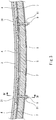
FIG. 2 is a sectional view of the double-shell tank taken along line II-II ofFIG. 1 . -
FIG. 3 is an enlarged view of part ofFIG. 2 . -
FIG. 4 is a sectional view taken along line IV-IV ofFIG. 3 . -
FIG. 5 is a bottom view as seen from line V-V ofFIG. 4 . -
FIG. 1 shows part of aship 1, on which a double-shell tank 2 according to one embodiment of the present invention is installed. - In the present embodiment, the double-
shell tank 2 is a cylindrical tank whose axial direction is parallel to the ship length direction. However, the double-shell tank 2 is not limited to such a shape, but may be, for example, spherical, cuboidal, or rectangular parallelepiped. - The double-
shell tank 2 includes aninner shell 3 storing liquefied gas and anouter shell 6 surrounding theinner shell 3. Avacuum space 21 is formed between theinner shell 3 and theouter shell 6. For example, the liquefied gas is liquefied petroleum gas (LPG, about - 45°C), liquefied ethylene gas (LEG, about -100°C), liquefied natural gas (LNG, about -160°C), liquefied oxygen (LO2, about -180°C), liquefied hydrogen (LH2, about -250°C), or liquefied helium (LHe, about -270°C). - As shown in
FIG. 1 andFIG. 2 , each of theinner shell 3 and theouter shell 6 is constituted by a body portion and hemispherical sealing portions. The body portion extends laterally with a constant cross-sectional shape. The hemispherical sealing portions seal openings on both sides of the body portion. Alternatively, each sealing portion may have a flat shape perpendicular to the body portion, or may be dish-shaped. The center line of the body portion of theouter shell 6 substantially coincides with the center line of the body portion of theinner shell 3. The diameter of the body portion of theouter shell 6 is greater than the diameter of theinner shell 3. - The
outer shell 6 is supported by a pair ofsaddles 12 provided on a ship bottom 11 at positions that are spaced apart from each other in the axial direction of the double-shell tank 2. A pair ofsupport members 22, which supports theinner shell 3 at the same positions as thesaddles 12, is disposed between theinner shell 3 and theouter shell 6. - In the
vacuum space 21, the entireinner shell 3 is covered by athermal insulator 5. In the present embodiment, thethermal insulator 5 is constituted by a plurality of thermal insulation sheets. However, in the drawings, the illustration of divisions between the thermal insulation sheets is omitted. The thermal insulation sheets are arranged along the outer surface of theinner shell 3 without gaps between the sheets. The thermal insulation sheets may form a single layer, or may be laminated together in the thickness direction to form a plurality of layers. - Each thermal insulation sheet has a multi-layered laminated structure. Specifically, each thermal insulation sheet includes radiation shield films and spacers that are stacked alternately. As one example, each radiation shield film may be aluminum foil, or may be a film obtained by vapor-depositing aluminum (or gold or silver) onto the surface of a resin sheet. Each spacer is a sheet having low thermal conductivity. For example, a resin net, woven fabric, non-woven fabric, paper, or a glass fiber material can be used as the sheet. Alternatively, each thermal insulation sheet may be made of glass wool.
- In the present embodiment, an
adsorbent 4 is disposed between theinner shell 3 and thethermal insulator 5. Theadsorbent 4 adsorbs gas molecules by physisorption. When a vacuum is drawn on thevacuum space 21, gases such as nitrogen, oxygen, and water vapor are released from, for example, the material surfaces of thethermal insulator 5, theinner shell 3, and theouter shell 6. Theadsorbent 4 serves to keep the degree of vacuum of thevacuum space 21 by adsorbing the gases released from, for example, the material surfaces of thethermal insulator 5, theinner shell 3, and theouter shell 6. - As shown in
FIG. 3 andFIG. 4 , theadsorbent 4 is placed on at least one metal sheet 7 (inFIG. 1 andFIG. 2 , the illustration of themetal sheet 7 is omitted for the sake of simplifying the drawings). The at least onemetal sheet 7 is mounted to theinner shell 3, such that at least part of themetal sheet 7 faces the bottom surface of theinner shell 3. The aforementionedthermal insulator 5 covers theinner shell 3 and themetal sheet 7. - The term "bottom surface" herein refers to a particular region of the outer surface of the
inner shell 3. The lowest point of the outer surface is the center of the region, and in the region, an angle formed between the normal line to the outer surface and the vertically downward direction is less than or equal to 45 degrees. In the present embodiment, the double-shell tank 2 is a cylindrical tank. Accordingly, the cross section of the bottom surface has a 90-degree arc shape, whereas the longitudinal section of the bottom surface has such a shape that a straight portion is present between 45-degree arcs. In a case where the double-shell tank 2 is a round tank, the sectional shape of the bottom surface is a 90-degree arc in any direction. - The above expression "the at least one
metal sheet 7 is ... such that at least part of themetal sheet 7 faces the bottom surface of theinner shell 3" means that at least part of the at least onemetal sheet 7 is present within such a positional range that the part of the at least onemetal sheet 7 overlaps the bottom surface of theinner shell 3. Desirably, all themetal sheets 7 are present within such a positional range that all themetal sheets 7 overlap the bottom surface of theinner shell 3. More desirably, the at least onemetal sheet 7 covers at least the lowest point of the bottom surface of theinner shell 3. - In the present embodiment, as shown in
FIG. 1 andFIG. 2 , theadsorbent 4 is disposed along the lower half of the body portion of theinner shell 3. Accordingly, similar to theadsorbent 4, a plurality ofmetal sheets 7 are disposed in a manner to face the lower half of the outer peripheral surface of the body portion of theinner shell 3. - The material of each
metal sheet 7 is the same as the material of theinner shell 3. For example, the material of theinner shell 3 and themetal sheet 7 is stainless steel, Ni-based alloy, or aluminum alloy. - In the present embodiment, each
metal sheet 7 is rectangular as shown inFIG. 5 . End portions ofadjacent metal sheets 7 overlap each other.Stud bolts 9 are provided on theinner shell 3 at positions corresponding to the four corners of eachmetal sheet 7. Thestud bolts 9 penetrate the overlapping portions of theadjacent metal sheets 7. - It should be noted that the
stud bolts 9 may penetrate the thermal insulation sheets that constitute thethermal insulator 5. Alternatively, the thermal insulation sheets may be disposed adjacent to each other withstud bolts 9 positioned therebetween, and each of thesestud bolts 9 may protrude from a gap between the thermal insulation sheets. - Each
stud bolt 9 is provided on theinner shell 3 via ametal base plate 31. Thestud bolt 9 is joined to thebase plate 31, for example, by a screwing structure or welding. Thebase plate 31 is joined to theinner shell 3, for example, by welding. In the illustrated example, thebase plate 31 has a circular shape. Alternatively, thebase plate 31 may have a square shape. - Although the material of the
stud bolt 9 is not particularly limited, for example, desirably, thestud bolt 9 is made of a material whose thermal conductivity is low, such as glass fiber reinforced plastic (GFRP). - Each
metal sheet 7 is in surface contact with thebase plates 31. For this reason, high thermal conductivity between theinner shell 3 and themetal sheet 7 is obtained. Eachbase plate 31 also functions as a spacer that forms a gap between themetal sheet 7 and theinner shell 3. - In the present embodiment, a plurality of openings 71 (see
FIG. 5 ) are formed in eachmetal sheet 7. Accordingly, gas molecules can collide with the adsorbent 4 through theopenings 71 of themetal sheet 7. Theopenings 71 may be through-holes drilled in the metal plate. Alternatively, eachmetal sheet 7 may be an expanded metal in which diamond-shapedopenings 71 are arranged in a staggered manner. However, since the gas molecules in thevacuum space 21 can enter from around themetal sheet 7 toward theadsorbent 4 along the outer surface of theinner shell 3, themetal sheet 7 may be a metal plate without theopenings 71. - The
above adsorbent 4 is a porous granular or powdery material enclosed in a bag. The bag enclosing theadsorbent 4 therein is fixed to themetal sheet 7 by rivets. For example, activated carbon, zeolite, silica gel, or alumina can be used as theadsorbent 4. - A
keep plate 8 is disposed on the outside of thethermal insulator 5. The keepplate 8 is fixed to theaforementioned stud bolts 9 bynuts 91, and retains themetal sheets 7 and the thermal insulation sheets constituting thethermal insulator 5. Specifically, thestud bolts 9 are used to fix themetal sheets 7 and the thermal insulation sheets, and the keepplate 8 presses thethermal insulator 5 and themetal sheets 7 onto thebase plates 31. For example, thekeep plate 8 is constituted by a plurality of bar-shaped members, each of which extends betweenadjacent stud bolts 9 in a bridging manner. - As described above, in the double-
shell tank 2 of the present embodiment, at least part of themetal sheet 7 having high thermal conductivity is mounted to theinner shell 3 in a manner to face the bottom surface of theinner shell 3, and themetal sheet 7 together with theinner shell 3 is covered by thethermal insulator 5. Accordingly, when the liquefied gas is injected into theinner shell 3, themetal sheet 7 is cooled to the same temperature as the temperature of the bottom surface of theinner shell 3. Since theadsorbent 4 is placed on themetal sheet 7, theadsorbent 4 can be cooled to the temperature of the bottom surface of theinner shell 3. In addition, since theadsorbent 4 is only required to be placed on themetal sheet 7, the advantageous effect can be obtained at low cost. - When the liquefied gas is taken out of the double-
shell tank 2, the liquefied gas remains in the lower part of the double-shell tank 2 until the double-shell tank 2 becomes empty. Thus, theadsorbent 4 can be cooled and a high degree of vacuum can be kept until immediately before the double-shell tank 2 becomes empty. - Further, in the present embodiment, since the
stud bolts 9 are used for fixing themetal sheets 7 and the thermal insulation sheets, both themetal sheets 7 and the thermal insulation sheets can be fixed by the sharedstud bolts 9. This makes it possible to simplify the structure. - The present invention is not limited to the above-described embodiment. Various modifications can be made without departing from the scope of the present invention.
- For example, the material of the
metal sheet 7 may be different from the material of theinner shell 3. However, in a case where the material of themetal sheet 7 is the same as the material of theinner shell 3 as in the above-described embodiment, when the liquefied gas is injected into theinner shell 3, although theinner shell 3 thermally contracts, themetal sheet 7 also thermally contracts with a linear expansion coefficient that is the same as a linear expansion coefficient with which theinner shell 3 thermally contracts. Therefore, when theinner shell 3 thermally contracts, positional deviation between theinner shell 3 and themetal sheet 7 relative to each other can be prevented. - Instead of providing the
base plates 31, end portions of themetal sheet 7 may be thickened, and thestud bolts 9 may be directly joined to theinner shell 3. - In the case of using the plurality of
metal sheets 7, it is not essential that end portions ofadjacent metal sheets 7 overlap each other. However, if the end portions of theadjacent metal sheets 7 overlap each other and thestud bolts 9 penetrate the overlapping portions as in the present embodiment, the number ofstud bolts 9 can be made as small as possible. - It is not essential that the
thermal insulator 5 be constituted by the thermal insulation sheets. For example, thethermal insulator 5 may be a granular material (e.g., pearlite) or glass wool that fills between theinner shell 3 and theouter shell 6. Alternatively, thethermal insulator 5 may be made of urethane foam. However, in the vacuum space, the thermal insulation sheets having the laminated structure as described in the above embodiment exert much higher thermal insulation performance than pearlite, glass wool, and urethane foam. Therefore, the present invention is particularly useful in a case where thethermal insulator 5 includes a plurality of thermal insulation sheets intended for use in a vacuum space. - The present invention is applicable not only to a tank installed on a ship, but also to a tank set on the ground. However, in the ship, sloshing occurs in the
inner shell 3 due to rolling and/or pitching of the hull. Even though such sloshing occurs, since themetal sheet 7 and theinner shell 3 are mechanically fastened together by thestud bolts 9, and also, themetal sheet 7 and theadsorbent 4 are fixed together by the rivets, theadsorbent 4 can be disposed stably even under such a swinging condition. Therefore, the configuration of the above-described embodiment is particularly useful for a tank installed on a ship. -
- 1
- ship
- 2
- double-shell tank
- 21
- vacuum space
- 3
- inner shell
- 4
- adsorbent
- 5
- thermal insulator
- 6
- outer shell
- 7
- metal sheet
- 8
- keep plate
- 9
- stud bolt
Claims (6)
- A double-shell tank comprising:an inner shell storing liquefied gas;an outer shell surrounding the inner shell, the outer shell forming a vacuum space between the inner shell and the outer shell;at least one metal sheet mounted to the inner shell, such that at least part of the metal sheet faces a bottom surface of the inner shell;an adsorbent placed on the metal sheet, the adsorbent adsorbing gas molecules by physisorption; anda thermal insulator covering the inner shell and the metal sheet.
- The double-shell tank according to claim 1, wherein
a material of the metal sheet is the same as a material of the inner shell. - The double-shell tank according to claim 1 or 2, wherein
a plurality of stud bolts are provided on the inner shell,
the thermal insulator includes a plurality of thermal insulation sheets, and
the plurality of stud bolts are used for fixing the metal sheet and the plurality of thermal insulation sheets. - The double-shell tank according to any one of claims 1 to 3, wherein
the at least one metal sheet includes a plurality of metal sheets, and
end portions of the metal sheets that are adjacent to each other overlap each other, and stud bolts provided on the inner shell penetrate the overlapping portions. - The double-shell tank according to any one of claims 1 to 4, wherein
the adsorbent is a porous granular or powdery material enclosed in a bag, and
a plurality of openings are formed in the metal sheet. - A ship comprising the double-shell tank according to any one of claims 1 to 5.
Applications Claiming Priority (2)
| Application Number | Priority Date | Filing Date | Title |
|---|---|---|---|
| JP2017200327 | 2017-10-16 | ||
| PCT/JP2018/037525 WO2019078048A1 (en) | 2017-10-16 | 2018-10-09 | Double shell tank, and ship |
Publications (3)
| Publication Number | Publication Date |
|---|---|
| EP3699476A1 true EP3699476A1 (en) | 2020-08-26 |
| EP3699476A4 EP3699476A4 (en) | 2021-07-07 |
| EP3699476B1 EP3699476B1 (en) | 2023-11-29 |
Family
ID=66172899
Family Applications (1)
| Application Number | Title | Priority Date | Filing Date |
|---|---|---|---|
| EP18868420.3A Active EP3699476B1 (en) | 2017-10-16 | 2018-10-09 | Double shell tank and ship |
Country Status (6)
| Country | Link |
|---|---|
| US (1) | US11247752B2 (en) |
| EP (1) | EP3699476B1 (en) |
| JP (1) | JP6860689B2 (en) |
| KR (1) | KR102295582B1 (en) |
| CN (1) | CN111213003B (en) |
| WO (1) | WO2019078048A1 (en) |
Cited By (1)
| Publication number | Priority date | Publication date | Assignee | Title |
|---|---|---|---|---|
| WO2025119853A1 (en) * | 2023-12-06 | 2025-06-12 | Gaztransport Et Technigaz | Wall for a sealed and thermally insulating tank for storing a liquefied gas |
Families Citing this family (9)
| Publication number | Priority date | Publication date | Assignee | Title |
|---|---|---|---|---|
| FR3106649B1 (en) * | 2020-01-24 | 2022-04-29 | Air Liquide | Mobile cryogenic tank and supply method |
| KR102814759B1 (en) * | 2020-06-22 | 2025-05-29 | 삼성중공업 주식회사 | Method for thermal insulation of vessel |
| KR102814748B1 (en) * | 2020-06-29 | 2025-05-29 | 삼성중공업 주식회사 | Method for thermal insulation of vessel |
| WO2022144971A1 (en) | 2020-12-28 | 2022-07-07 | 川崎重工業株式会社 | Multi-shell tank and vessel |
| KR102513987B1 (en) * | 2022-05-06 | 2023-03-27 | 에스탱크엔지니어링(주) | Storage tank for liquefied hydrogen |
| KR102513985B1 (en) * | 2022-05-06 | 2023-03-24 | 에스탱크엔지니어링(주) | Storage tank for liquefied hydrogen |
| JP2024016651A (en) * | 2022-07-26 | 2024-02-07 | 川崎重工業株式会社 | multi-shell structure |
| CN116238815A (en) * | 2023-03-22 | 2023-06-09 | 江苏大学 | A low-carbon constant temperature logistics transportation storage tank based on thermal energy storage |
| JP2025079827A (en) * | 2025-01-30 | 2025-05-22 | 東京瓦斯株式会社 | Cryogenic Liquid Storage System |
Family Cites Families (21)
| Publication number | Priority date | Publication date | Assignee | Title |
|---|---|---|---|---|
| US2834187A (en) * | 1954-09-10 | 1958-05-13 | Union Carbide Corp | Refrigerated container for liquefied gases |
| US2900800A (en) * | 1956-01-05 | 1959-08-25 | Union Carbide Corp | Method and apparatus for maintaining efficiency of vacuum insulation |
| US3122004A (en) | 1961-03-27 | 1964-02-25 | Union Carbide Corp | Apparatus for cryogenic refrigeration |
| FR1318320A (en) | 1961-03-27 | 1963-02-15 | Union Carbide Corp | Method and device for producing cryogenic refrigeration |
| US3698589A (en) * | 1969-12-29 | 1972-10-17 | Union Carbide Corp | Cryogenic storage apparatus |
| US4055268A (en) | 1975-11-18 | 1977-10-25 | Union Carbide Corporation | Cryogenic storage container |
| DE2657904A1 (en) * | 1975-12-30 | 1977-07-14 | Osaka Oxygen Ind | THERMAL CONTAINER FOR LIQUID GASES AND FACING ALLOY FOR IT |
| US4394929A (en) * | 1981-04-10 | 1983-07-26 | Union Carbide Corporation | Cryogenic liquid storage container having an improved access conduit |
| DE3600298A1 (en) | 1985-03-07 | 1986-09-11 | Messer Griesheim Gmbh, 6000 Frankfurt | METHOD FOR INSERTING AN ADSORPTION AGENT |
| JPS62194298U (en) * | 1986-05-30 | 1987-12-10 | ||
| JPS62200898U (en) * | 1986-06-11 | 1987-12-21 | ||
| JPS63152097U (en) * | 1987-03-25 | 1988-10-05 | ||
| JPS63318398A (en) | 1987-06-18 | 1988-12-27 | Kobe Steel Ltd | Superlow temperature container |
| JPH02113099U (en) * | 1989-02-23 | 1990-09-10 | ||
| US5726908A (en) | 1995-03-20 | 1998-03-10 | Figgie International Inc. | Liquid quantity sensor and method |
| US6708502B1 (en) | 2002-09-27 | 2004-03-23 | The Regents Of The University Of California | Lightweight cryogenic-compatible pressure vessels for vehicular fuel storage |
| KR100991994B1 (en) * | 2008-03-28 | 2010-11-04 | 삼성중공업 주식회사 | LNG carrier with liquefied gas loading / unloading system |
| CN104995449B (en) * | 2013-03-01 | 2017-11-28 | 松下知识产权经营株式会社 | Heat-insulated container and heat insulating structure body |
| CN107461604B (en) * | 2013-09-12 | 2019-07-30 | 松下知识产权经营株式会社 | Insulated container with vacuum insulation |
| CN207514562U (en) | 2014-06-04 | 2018-06-19 | 松下知识产权经营株式会社 | Insulators and Insulated Containers |
| EP3239589A4 (en) * | 2014-12-26 | 2017-12-13 | Panasonic Intellectual Property Management Co., Ltd. | Heat-insulating container provided with vacuum heat-insulating material, vacuum heat-insulating material, and tanker provided with heat-insulating container |
-
2018
- 2018-10-09 JP JP2019549215A patent/JP6860689B2/en active Active
- 2018-10-09 US US16/756,794 patent/US11247752B2/en active Active
- 2018-10-09 CN CN201880066882.8A patent/CN111213003B/en active Active
- 2018-10-09 KR KR1020207013131A patent/KR102295582B1/en active Active
- 2018-10-09 WO PCT/JP2018/037525 patent/WO2019078048A1/en not_active Ceased
- 2018-10-09 EP EP18868420.3A patent/EP3699476B1/en active Active
Cited By (2)
| Publication number | Priority date | Publication date | Assignee | Title |
|---|---|---|---|---|
| WO2025119853A1 (en) * | 2023-12-06 | 2025-06-12 | Gaztransport Et Technigaz | Wall for a sealed and thermally insulating tank for storing a liquefied gas |
| FR3156500A1 (en) * | 2023-12-06 | 2025-06-13 | Gaztransport Et Technigaz | Wall for a sealed and thermally insulating tank for storing liquefied gas |
Also Published As
| Publication number | Publication date |
|---|---|
| US11247752B2 (en) | 2022-02-15 |
| EP3699476B1 (en) | 2023-11-29 |
| EP3699476A4 (en) | 2021-07-07 |
| JPWO2019078048A1 (en) | 2020-10-22 |
| KR102295582B1 (en) | 2021-08-30 |
| WO2019078048A1 (en) | 2019-04-25 |
| JP6860689B2 (en) | 2021-04-21 |
| CN111213003A (en) | 2020-05-29 |
| US20200239110A1 (en) | 2020-07-30 |
| CN111213003B (en) | 2021-09-21 |
| KR20200060506A (en) | 2020-05-29 |
Similar Documents
| Publication | Publication Date | Title |
|---|---|---|
| US11247752B2 (en) | Double-shell tank and ship | |
| US11906110B2 (en) | Tank container for transport and storage of cryogenic liquefied gases | |
| KR20250004680A (en) | Walls for sealed and insulated containers | |
| JP7601908B2 (en) | Multi-hull tanks and vessels | |
| KR20120035952A (en) | Cargo containment | |
| KR20250004716A (en) | Walls for sealed and insulated containers | |
| KR20100090036A (en) | Heat insulation structure and cryogenic liquid storage tank having the same | |
| KR101419821B1 (en) | Dual structure of storing container for liquefied natural gas | |
| RU2600419C1 (en) | Membrane tank for liquefied natural gas (vm type) | |
| KR101589118B1 (en) | Pressurized container for liquefied gas | |
| KR100998554B1 (en) | Insulation structure of LNG carrier cargo hold | |
| KR101422594B1 (en) | Container For Storing Liquefied Gas | |
| JP2013053655A (en) | Cold insulation structure for liquefied gas tank, liquefied gas tank, and floating structure | |
| KR102651474B1 (en) | Insulation System of Liquefied Natural Gas Storage Tank | |
| KR20140021198A (en) | Insulation system for membrane type lng cargo tank | |
| KR20130126294A (en) | Dual structure of storing container for liquefied natural gas | |
| KR20080104801A (en) | Insulation Structure of LAN Carrier Using Airgel | |
| JPH04258598A (en) | Vacuum type heat insulating panel for super low temperature cargo storage tank | |
| JP2022035616A (en) | Liquified gas carrier | |
| KR20170034548A (en) | Insulation Box Of Cargo Tank And Manufacturing Method Of The Same | |
| JP7257730B2 (en) | Cryogenic liquid storage tank | |
| KR20130126293A (en) | Dual structure of storing container for liquefied natural gas | |
| KR20120013248A (en) | Insulation boards and liquefied natural gas storage tanks comprising the same | |
| JP2022133232A (en) | double shell liquid hydrogen tank | |
| KR20180034850A (en) | Liquefied gas storage tank |
Legal Events
| Date | Code | Title | Description |
|---|---|---|---|
| STAA | Information on the status of an ep patent application or granted ep patent |
Free format text: STATUS: THE INTERNATIONAL PUBLICATION HAS BEEN MADE |
|
| PUAI | Public reference made under article 153(3) epc to a published international application that has entered the european phase |
Free format text: ORIGINAL CODE: 0009012 |
|
| STAA | Information on the status of an ep patent application or granted ep patent |
Free format text: STATUS: REQUEST FOR EXAMINATION WAS MADE |
|
| 17P | Request for examination filed |
Effective date: 20200427 |
|
| AK | Designated contracting states |
Kind code of ref document: A1 Designated state(s): AL AT BE BG CH CY CZ DE DK EE ES FI FR GB GR HR HU IE IS IT LI LT LU LV MC MK MT NL NO PL PT RO RS SE SI SK SM TR |
|
| AX | Request for extension of the european patent |
Extension state: BA ME |
|
| DAV | Request for validation of the european patent (deleted) | ||
| DAX | Request for extension of the european patent (deleted) | ||
| A4 | Supplementary search report drawn up and despatched |
Effective date: 20210609 |
|
| RIC1 | Information provided on ipc code assigned before grant |
Ipc: F17C 3/08 20060101AFI20210602BHEP Ipc: B63B 25/08 20060101ALI20210602BHEP Ipc: B65D 90/06 20060101ALI20210602BHEP Ipc: F17C 3/04 20060101ALI20210602BHEP |
|
| GRAP | Despatch of communication of intention to grant a patent |
Free format text: ORIGINAL CODE: EPIDOSNIGR1 |
|
| STAA | Information on the status of an ep patent application or granted ep patent |
Free format text: STATUS: GRANT OF PATENT IS INTENDED |
|
| INTG | Intention to grant announced |
Effective date: 20230615 |
|
| GRAS | Grant fee paid |
Free format text: ORIGINAL CODE: EPIDOSNIGR3 |
|
| GRAA | (expected) grant |
Free format text: ORIGINAL CODE: 0009210 |
|
| STAA | Information on the status of an ep patent application or granted ep patent |
Free format text: STATUS: THE PATENT HAS BEEN GRANTED |
|
| AK | Designated contracting states |
Kind code of ref document: B1 Designated state(s): AL AT BE BG CH CY CZ DE DK EE ES FI FR GB GR HR HU IE IS IT LI LT LU LV MC MK MT NL NO PL PT RO RS SE SI SK SM TR |
|
| REG | Reference to a national code |
Ref country code: GB Ref legal event code: FG4D |
|
| REG | Reference to a national code |
Ref country code: CH Ref legal event code: EP |
|
| REG | Reference to a national code |
Ref country code: DE Ref legal event code: R096 Ref document number: 602018061996 Country of ref document: DE |
|
| REG | Reference to a national code |
Ref country code: IE Ref legal event code: FG4D |
|
| REG | Reference to a national code |
Ref country code: LT Ref legal event code: MG9D |
|
| REG | Reference to a national code |
Ref country code: NL Ref legal event code: MP Effective date: 20231129 |
|
| PG25 | Lapsed in a contracting state [announced via postgrant information from national office to epo] |
Ref country code: GR Free format text: LAPSE BECAUSE OF FAILURE TO SUBMIT A TRANSLATION OF THE DESCRIPTION OR TO PAY THE FEE WITHIN THE PRESCRIBED TIME-LIMIT Effective date: 20240301 |
|
| PG25 | Lapsed in a contracting state [announced via postgrant information from national office to epo] |
Ref country code: IS Free format text: LAPSE BECAUSE OF FAILURE TO SUBMIT A TRANSLATION OF THE DESCRIPTION OR TO PAY THE FEE WITHIN THE PRESCRIBED TIME-LIMIT Effective date: 20240329 |
|
| PG25 | Lapsed in a contracting state [announced via postgrant information from national office to epo] |
Ref country code: LT Free format text: LAPSE BECAUSE OF FAILURE TO SUBMIT A TRANSLATION OF THE DESCRIPTION OR TO PAY THE FEE WITHIN THE PRESCRIBED TIME-LIMIT Effective date: 20231129 |
|
| PG25 | Lapsed in a contracting state [announced via postgrant information from national office to epo] |
Ref country code: ES Free format text: LAPSE BECAUSE OF FAILURE TO SUBMIT A TRANSLATION OF THE DESCRIPTION OR TO PAY THE FEE WITHIN THE PRESCRIBED TIME-LIMIT Effective date: 20231129 |
|
| PG25 | Lapsed in a contracting state [announced via postgrant information from national office to epo] |
Ref country code: LT Free format text: LAPSE BECAUSE OF FAILURE TO SUBMIT A TRANSLATION OF THE DESCRIPTION OR TO PAY THE FEE WITHIN THE PRESCRIBED TIME-LIMIT Effective date: 20231129 Ref country code: IS Free format text: LAPSE BECAUSE OF FAILURE TO SUBMIT A TRANSLATION OF THE DESCRIPTION OR TO PAY THE FEE WITHIN THE PRESCRIBED TIME-LIMIT Effective date: 20240329 Ref country code: GR Free format text: LAPSE BECAUSE OF FAILURE TO SUBMIT A TRANSLATION OF THE DESCRIPTION OR TO PAY THE FEE WITHIN THE PRESCRIBED TIME-LIMIT Effective date: 20240301 Ref country code: ES Free format text: LAPSE BECAUSE OF FAILURE TO SUBMIT A TRANSLATION OF THE DESCRIPTION OR TO PAY THE FEE WITHIN THE PRESCRIBED TIME-LIMIT Effective date: 20231129 Ref country code: BG Free format text: LAPSE BECAUSE OF FAILURE TO SUBMIT A TRANSLATION OF THE DESCRIPTION OR TO PAY THE FEE WITHIN THE PRESCRIBED TIME-LIMIT Effective date: 20240229 |
|
| REG | Reference to a national code |
Ref country code: AT Ref legal event code: MK05 Ref document number: 1636466 Country of ref document: AT Kind code of ref document: T Effective date: 20231129 |
|
| PG25 | Lapsed in a contracting state [announced via postgrant information from national office to epo] |
Ref country code: NL Free format text: LAPSE BECAUSE OF FAILURE TO SUBMIT A TRANSLATION OF THE DESCRIPTION OR TO PAY THE FEE WITHIN THE PRESCRIBED TIME-LIMIT Effective date: 20231129 |
|
| PG25 | Lapsed in a contracting state [announced via postgrant information from national office to epo] |
Ref country code: SE Free format text: LAPSE BECAUSE OF FAILURE TO SUBMIT A TRANSLATION OF THE DESCRIPTION OR TO PAY THE FEE WITHIN THE PRESCRIBED TIME-LIMIT Effective date: 20231129 Ref country code: RS Free format text: LAPSE BECAUSE OF FAILURE TO SUBMIT A TRANSLATION OF THE DESCRIPTION OR TO PAY THE FEE WITHIN THE PRESCRIBED TIME-LIMIT Effective date: 20231129 Ref country code: PL Free format text: LAPSE BECAUSE OF FAILURE TO SUBMIT A TRANSLATION OF THE DESCRIPTION OR TO PAY THE FEE WITHIN THE PRESCRIBED TIME-LIMIT Effective date: 20231129 Ref country code: NL Free format text: LAPSE BECAUSE OF FAILURE TO SUBMIT A TRANSLATION OF THE DESCRIPTION OR TO PAY THE FEE WITHIN THE PRESCRIBED TIME-LIMIT Effective date: 20231129 Ref country code: LV Free format text: LAPSE BECAUSE OF FAILURE TO SUBMIT A TRANSLATION OF THE DESCRIPTION OR TO PAY THE FEE WITHIN THE PRESCRIBED TIME-LIMIT Effective date: 20231129 Ref country code: HR Free format text: LAPSE BECAUSE OF FAILURE TO SUBMIT A TRANSLATION OF THE DESCRIPTION OR TO PAY THE FEE WITHIN THE PRESCRIBED TIME-LIMIT Effective date: 20231129 |
|
| PG25 | Lapsed in a contracting state [announced via postgrant information from national office to epo] |
Ref country code: DK Free format text: LAPSE BECAUSE OF FAILURE TO SUBMIT A TRANSLATION OF THE DESCRIPTION OR TO PAY THE FEE WITHIN THE PRESCRIBED TIME-LIMIT Effective date: 20231129 |
|
| PG25 | Lapsed in a contracting state [announced via postgrant information from national office to epo] |
Ref country code: CZ Free format text: LAPSE BECAUSE OF FAILURE TO SUBMIT A TRANSLATION OF THE DESCRIPTION OR TO PAY THE FEE WITHIN THE PRESCRIBED TIME-LIMIT Effective date: 20231129 Ref country code: AT Free format text: LAPSE BECAUSE OF FAILURE TO SUBMIT A TRANSLATION OF THE DESCRIPTION OR TO PAY THE FEE WITHIN THE PRESCRIBED TIME-LIMIT Effective date: 20231129 |
|
| PG25 | Lapsed in a contracting state [announced via postgrant information from national office to epo] |
Ref country code: SK Free format text: LAPSE BECAUSE OF FAILURE TO SUBMIT A TRANSLATION OF THE DESCRIPTION OR TO PAY THE FEE WITHIN THE PRESCRIBED TIME-LIMIT Effective date: 20231129 |
|
| PG25 | Lapsed in a contracting state [announced via postgrant information from national office to epo] |
Ref country code: SM Free format text: LAPSE BECAUSE OF FAILURE TO SUBMIT A TRANSLATION OF THE DESCRIPTION OR TO PAY THE FEE WITHIN THE PRESCRIBED TIME-LIMIT Effective date: 20231129 Ref country code: SK Free format text: LAPSE BECAUSE OF FAILURE TO SUBMIT A TRANSLATION OF THE DESCRIPTION OR TO PAY THE FEE WITHIN THE PRESCRIBED TIME-LIMIT Effective date: 20231129 Ref country code: RO Free format text: LAPSE BECAUSE OF FAILURE TO SUBMIT A TRANSLATION OF THE DESCRIPTION OR TO PAY THE FEE WITHIN THE PRESCRIBED TIME-LIMIT Effective date: 20231129 Ref country code: IT Free format text: LAPSE BECAUSE OF FAILURE TO SUBMIT A TRANSLATION OF THE DESCRIPTION OR TO PAY THE FEE WITHIN THE PRESCRIBED TIME-LIMIT Effective date: 20231129 Ref country code: EE Free format text: LAPSE BECAUSE OF FAILURE TO SUBMIT A TRANSLATION OF THE DESCRIPTION OR TO PAY THE FEE WITHIN THE PRESCRIBED TIME-LIMIT Effective date: 20231129 Ref country code: DK Free format text: LAPSE BECAUSE OF FAILURE TO SUBMIT A TRANSLATION OF THE DESCRIPTION OR TO PAY THE FEE WITHIN THE PRESCRIBED TIME-LIMIT Effective date: 20231129 Ref country code: CZ Free format text: LAPSE BECAUSE OF FAILURE TO SUBMIT A TRANSLATION OF THE DESCRIPTION OR TO PAY THE FEE WITHIN THE PRESCRIBED TIME-LIMIT Effective date: 20231129 Ref country code: AT Free format text: LAPSE BECAUSE OF FAILURE TO SUBMIT A TRANSLATION OF THE DESCRIPTION OR TO PAY THE FEE WITHIN THE PRESCRIBED TIME-LIMIT Effective date: 20231129 |
|
| PG25 | Lapsed in a contracting state [announced via postgrant information from national office to epo] |
Ref country code: PT Free format text: LAPSE BECAUSE OF FAILURE TO SUBMIT A TRANSLATION OF THE DESCRIPTION OR TO PAY THE FEE WITHIN THE PRESCRIBED TIME-LIMIT Effective date: 20240401 |
|
| PG25 | Lapsed in a contracting state [announced via postgrant information from national office to epo] |
Ref country code: PT Free format text: LAPSE BECAUSE OF FAILURE TO SUBMIT A TRANSLATION OF THE DESCRIPTION OR TO PAY THE FEE WITHIN THE PRESCRIBED TIME-LIMIT Effective date: 20240401 |
|
| REG | Reference to a national code |
Ref country code: DE Ref legal event code: R097 Ref document number: 602018061996 Country of ref document: DE |
|
| PLBE | No opposition filed within time limit |
Free format text: ORIGINAL CODE: 0009261 |
|
| STAA | Information on the status of an ep patent application or granted ep patent |
Free format text: STATUS: NO OPPOSITION FILED WITHIN TIME LIMIT |
|
| PG25 | Lapsed in a contracting state [announced via postgrant information from national office to epo] |
Ref country code: SI Free format text: LAPSE BECAUSE OF FAILURE TO SUBMIT A TRANSLATION OF THE DESCRIPTION OR TO PAY THE FEE WITHIN THE PRESCRIBED TIME-LIMIT Effective date: 20231129 |
|
| PG25 | Lapsed in a contracting state [announced via postgrant information from national office to epo] |
Ref country code: SI Free format text: LAPSE BECAUSE OF FAILURE TO SUBMIT A TRANSLATION OF THE DESCRIPTION OR TO PAY THE FEE WITHIN THE PRESCRIBED TIME-LIMIT Effective date: 20231129 |
|
| 26N | No opposition filed |
Effective date: 20240830 |
|
| REG | Reference to a national code |
Ref country code: DE Ref legal event code: R119 Ref document number: 602018061996 Country of ref document: DE |
|
| REG | Reference to a national code |
Ref country code: CH Ref legal event code: PL |
|
| GBPC | Gb: european patent ceased through non-payment of renewal fee |
Effective date: 20241009 |
|
| PG25 | Lapsed in a contracting state [announced via postgrant information from national office to epo] |
Ref country code: MC Free format text: LAPSE BECAUSE OF FAILURE TO SUBMIT A TRANSLATION OF THE DESCRIPTION OR TO PAY THE FEE WITHIN THE PRESCRIBED TIME-LIMIT Effective date: 20231129 |
|
| PG25 | Lapsed in a contracting state [announced via postgrant information from national office to epo] |
Ref country code: DE Free format text: LAPSE BECAUSE OF NON-PAYMENT OF DUE FEES Effective date: 20250501 |
|
| PG25 | Lapsed in a contracting state [announced via postgrant information from national office to epo] |
Ref country code: GB Free format text: LAPSE BECAUSE OF NON-PAYMENT OF DUE FEES Effective date: 20241009 |
|
| PG25 | Lapsed in a contracting state [announced via postgrant information from national office to epo] |
Ref country code: LU Free format text: LAPSE BECAUSE OF NON-PAYMENT OF DUE FEES Effective date: 20241009 Ref country code: BE Free format text: LAPSE BECAUSE OF NON-PAYMENT OF DUE FEES Effective date: 20241031 |
|
| PG25 | Lapsed in a contracting state [announced via postgrant information from national office to epo] |
Ref country code: FR Free format text: LAPSE BECAUSE OF NON-PAYMENT OF DUE FEES Effective date: 20241031 |
|
| PG25 | Lapsed in a contracting state [announced via postgrant information from national office to epo] |
Ref country code: CH Free format text: LAPSE BECAUSE OF NON-PAYMENT OF DUE FEES Effective date: 20241031 |
|
| REG | Reference to a national code |
Ref country code: BE Ref legal event code: MM Effective date: 20241031 |
|
| PG25 | Lapsed in a contracting state [announced via postgrant information from national office to epo] |
Ref country code: FI Free format text: LAPSE BECAUSE OF FAILURE TO SUBMIT A TRANSLATION OF THE DESCRIPTION OR TO PAY THE FEE WITHIN THE PRESCRIBED TIME-LIMIT Effective date: 20231129 |
|
| PG25 | Lapsed in a contracting state [announced via postgrant information from national office to epo] |
Ref country code: IE Free format text: LAPSE BECAUSE OF NON-PAYMENT OF DUE FEES Effective date: 20241009 |
|
| PGFP | Annual fee paid to national office [announced via postgrant information from national office to epo] |
Ref country code: NO Payment date: 20251009 Year of fee payment: 8 |
|
| PG25 | Lapsed in a contracting state [announced via postgrant information from national office to epo] |
Ref country code: CY Free format text: LAPSE BECAUSE OF FAILURE TO SUBMIT A TRANSLATION OF THE DESCRIPTION OR TO PAY THE FEE WITHIN THE PRESCRIBED TIME-LIMIT; INVALID AB INITIO Effective date: 20181009 |
|
| PG25 | Lapsed in a contracting state [announced via postgrant information from national office to epo] |
Ref country code: HU Free format text: LAPSE BECAUSE OF FAILURE TO SUBMIT A TRANSLATION OF THE DESCRIPTION OR TO PAY THE FEE WITHIN THE PRESCRIBED TIME-LIMIT; INVALID AB INITIO Effective date: 20181009 |
|
| PG25 | Lapsed in a contracting state [announced via postgrant information from national office to epo] |
Ref country code: TR Free format text: LAPSE BECAUSE OF FAILURE TO SUBMIT A TRANSLATION OF THE DESCRIPTION OR TO PAY THE FEE WITHIN THE PRESCRIBED TIME-LIMIT Effective date: 20231129 |