EP3699402A1 - Valve device and steam turbine - Google Patents
Valve device and steam turbine Download PDFInfo
- Publication number
- EP3699402A1 EP3699402A1 EP20158206.1A EP20158206A EP3699402A1 EP 3699402 A1 EP3699402 A1 EP 3699402A1 EP 20158206 A EP20158206 A EP 20158206A EP 3699402 A1 EP3699402 A1 EP 3699402A1
- Authority
- EP
- European Patent Office
- Prior art keywords
- valve body
- rod
- valve
- portions
- flow path
- Prior art date
- Legal status (The legal status is an assumption and is not a legal conclusion. Google has not performed a legal analysis and makes no representation as to the accuracy of the status listed.)
- Granted
Links
Images


Classifications
-
- F—MECHANICAL ENGINEERING; LIGHTING; HEATING; WEAPONS; BLASTING
- F01—MACHINES OR ENGINES IN GENERAL; ENGINE PLANTS IN GENERAL; STEAM ENGINES
- F01D—NON-POSITIVE DISPLACEMENT MACHINES OR ENGINES, e.g. STEAM TURBINES
- F01D17/00—Regulating or controlling by varying flow
- F01D17/10—Final actuators
- F01D17/12—Final actuators arranged in stator parts
- F01D17/14—Final actuators arranged in stator parts varying effective cross-sectional area of nozzles or guide conduits
- F01D17/141—Final actuators arranged in stator parts varying effective cross-sectional area of nozzles or guide conduits by means of shiftable members or valves obturating part of the flow path
- F01D17/145—Final actuators arranged in stator parts varying effective cross-sectional area of nozzles or guide conduits by means of shiftable members or valves obturating part of the flow path by means of valves, e.g. for steam turbines
-
- F—MECHANICAL ENGINEERING; LIGHTING; HEATING; WEAPONS; BLASTING
- F16—ENGINEERING ELEMENTS AND UNITS; GENERAL MEASURES FOR PRODUCING AND MAINTAINING EFFECTIVE FUNCTIONING OF MACHINES OR INSTALLATIONS; THERMAL INSULATION IN GENERAL
- F16K—VALVES; TAPS; COCKS; ACTUATING-FLOATS; DEVICES FOR VENTING OR AERATING
- F16K31/00—Actuating devices; Operating means; Releasing devices
- F16K31/44—Mechanical actuating means
-
- F—MECHANICAL ENGINEERING; LIGHTING; HEATING; WEAPONS; BLASTING
- F01—MACHINES OR ENGINES IN GENERAL; ENGINE PLANTS IN GENERAL; STEAM ENGINES
- F01D—NON-POSITIVE DISPLACEMENT MACHINES OR ENGINES, e.g. STEAM TURBINES
- F01D17/00—Regulating or controlling by varying flow
- F01D17/10—Final actuators
-
- F—MECHANICAL ENGINEERING; LIGHTING; HEATING; WEAPONS; BLASTING
- F01—MACHINES OR ENGINES IN GENERAL; ENGINE PLANTS IN GENERAL; STEAM ENGINES
- F01D—NON-POSITIVE DISPLACEMENT MACHINES OR ENGINES, e.g. STEAM TURBINES
- F01D17/00—Regulating or controlling by varying flow
- F01D17/10—Final actuators
- F01D17/12—Final actuators arranged in stator parts
- F01D17/18—Final actuators arranged in stator parts varying effective number of nozzles or guide conduits, e.g. sequentially operable valves for steam turbines
-
- F—MECHANICAL ENGINEERING; LIGHTING; HEATING; WEAPONS; BLASTING
- F01—MACHINES OR ENGINES IN GENERAL; ENGINE PLANTS IN GENERAL; STEAM ENGINES
- F01D—NON-POSITIVE DISPLACEMENT MACHINES OR ENGINES, e.g. STEAM TURBINES
- F01D25/00—Component parts, details, or accessories, not provided for in, or of interest apart from, other groups
- F01D25/24—Casings; Casing parts, e.g. diaphragms, casing fastenings
-
- F—MECHANICAL ENGINEERING; LIGHTING; HEATING; WEAPONS; BLASTING
- F05—INDEXING SCHEMES RELATING TO ENGINES OR PUMPS IN VARIOUS SUBCLASSES OF CLASSES F01-F04
- F05D—INDEXING SCHEME FOR ASPECTS RELATING TO NON-POSITIVE-DISPLACEMENT MACHINES OR ENGINES, GAS-TURBINES OR JET-PROPULSION PLANTS
- F05D2220/00—Application
- F05D2220/30—Application in turbines
- F05D2220/31—Application in turbines in steam turbines
-
- F—MECHANICAL ENGINEERING; LIGHTING; HEATING; WEAPONS; BLASTING
- F05—INDEXING SCHEMES RELATING TO ENGINES OR PUMPS IN VARIOUS SUBCLASSES OF CLASSES F01-F04
- F05D—INDEXING SCHEME FOR ASPECTS RELATING TO NON-POSITIVE-DISPLACEMENT MACHINES OR ENGINES, GAS-TURBINES OR JET-PROPULSION PLANTS
- F05D2220/00—Application
- F05D2220/70—Application in combination with
- F05D2220/72—Application in combination with a steam turbine
-
- Y—GENERAL TAGGING OF NEW TECHNOLOGICAL DEVELOPMENTS; GENERAL TAGGING OF CROSS-SECTIONAL TECHNOLOGIES SPANNING OVER SEVERAL SECTIONS OF THE IPC; TECHNICAL SUBJECTS COVERED BY FORMER USPC CROSS-REFERENCE ART COLLECTIONS [XRACs] AND DIGESTS
- Y10—TECHNICAL SUBJECTS COVERED BY FORMER USPC
- Y10T—TECHNICAL SUBJECTS COVERED BY FORMER US CLASSIFICATION
- Y10T137/00—Fluid handling
- Y10T137/8593—Systems
- Y10T137/87917—Flow path with serial valves and/or closures
Definitions
- the present invention relates to a valve device and a steam turbine.
- a steam turbine rotates and drives a rotor by means of steam supplied from a boiler.
- the steam turbine transmits the rotation of the rotor to operate a compressor or a generator.
- an adjusting valve or a stop valve is provided to supply steam from the boiler to a turbine main body.
- the flow rate of steam supplied to the turbine main body can be adjusted by adjusting the opening degree of the adjusting valve.
- the stop valve is in an opened state. Accordingly, steam is supplied to the turbine main body from the boiler through a steam supply pipe.
- the stop valve enters a closed state and supply of steam from the boiler to the turbine main body is stopped.
- a valve device in which such an adjusting valve and such a stop valve are integrated with each other is described.
- a main steam stop valve which is a stop valve
- a steam-regulating valve which is an adjusting valve
- a valve rod of the main steam stop valve is movable in a horizontal direction
- a valve rod of the steam-regulating valve is movable in a vertical direction.
- an actuator such as a hydraulic cylinder for moving a rod (valve rod) of the main steam stop valve in the horizontal direction is provided to protrude at an outer side of the valve rod in the horizontal direction.
- the valve device becomes large in the horizontal direction.
- the shapes of a flow path of the main steam stop valve and a flow path of the steam-regulating valve, which are formed in a valve casing become complicated by being curved a plurality of times.
- the rod be moved smoothly without use of the rod's own weight when the rod of the main steam stop valve is moved in the horizontal direction.
- a structure in which a guide with a very narrow clearance in a direction intersecting the horizontal direction is provided with respect to the rod such that the valve rod is moved only in the horizontal direction is conceivable.
- the present invention provides a valve device and a steam turbine with which it is possible to secure stable movement of a rod while securing an assembling property.
- a valve device including a valve casing in which an inlet flow path into which fluid is configured to flow, an intermediate flow path that communicates with the inlet flow path and through which the fluid is configured to flow in a direction intersecting the inlet flow path, and an outlet flow path that communicates with the intermediate flow path and through which the fluid is configured to flow in a direction intersecting the intermediate flow path are formed, an outlet valve seat portion provided in the outlet flow path, an outlet valve body that comes into contact with the outlet valve seat portion such that the outlet flow path is closed, an outlet rod portion that extends along a first center axis and of which an end portion on a first side in a first center axis direction is connected to the outlet valve body, a linkage shaft portion that is configured to linearly move the outlet rod portion in the first center axis direction, an intermediate valve seat portion provided in the intermediate flow path, an intermediate valve body that comes into contact with the intermediate valve seat portion such that the intermediate flow path is closed, an intermediate rod portion that extends along
- the intermediate rod portion is inserted into the rod insertion hole, which is formed in a lid portion, in a wobbling state. Therefore, movement of the intermediate rod portion being impeded due to adhesion of scale is suppressed. As a result, it is possible to secure stable movement of the intermediate rod portion. Furthermore, a portion of the piston rod portion is disposed inside the cylinder portion. Therefore, the piston rod portion is exposed to the control oil. As a result, the control oil adheres to the outer circumferential surface of the piston rod portion and thus sliding characteristics are significantly enhanced. Therefore, even when there is almost no gap between the inner circumferential surface of the rod guide portion and the outer circumferential surface of the piston rod portion, high slidability can be secured between the rod guide portion and the piston rod portion. Accordingly, it is possible to stably move the piston rod portion in a vertical direction with high accuracy.
- a second aspect of the present invention provides the valve device according to the first aspect in which at least a portion of the rod guide portion may be disposed inside the cylinder portion.
- the rod guide portion is exposed to the control oil in the cylinder portion.
- the control oil also adheres to the inner circumferential surface of the rod guide portion. Therefore, sliding characteristics are improved not only at the outer circumferential surface of the piston rod portion but also at the inner circumferential surface of the rod guide portions. Accordingly, even when there is almost no gap between the inner circumferential surface of the rod guide portion and the outer circumferential surface of the piston rod portions, significantly high slidability can be secured between the rod guide portion and the piston rod portion. Therefore, it is possible to more stably move the piston rod portion in the vertical direction with high accuracy.
- a third aspect of the present invention provides the valve device according to the first aspect or the second aspect in which the valve casing may include a first surface in which the rod insertion hole is formed at a position facing the intermediate valve seat portion, the intermediate valve body may include a valve body rear surface that faces the first surface and to which the intermediate rod portion is connected, and a projection portion that has a tubular shape surrounding a center axis of the intermediate rod portion and protrudes toward the first surface from the valve body rear surface, and the projection portion may come into contact with the first surface when the intermediate rod portion is moved such that the intermediate flow path is opened.
- the projection portion serves as a sealing portion between the lid portion and the intermediate valve body. Accordingly, even when the intermediate flow path is opened and the fluid flows into a valve casing main body, inflow of the fluid into the rod insertion hole can be suppressed. As a result, the fluid inside the valve casing main body can be restrained from leaking out from the valve casing main body via the rod insertion hole.
- a fourth aspect of the present invention provides the valve device according to any of the first aspect to the third aspect in which the intermediate valve body may include a slave valve body portion that is fixed to a tip end of the intermediate rod portion, a main valve body portion in which an accommodation space accommodating the slave valve body portion is formed and that includes a valve body through-hole through which the accommodation space and the outlet flow path communicate with each other, and a slave valve body guide portion that is fixed to the main valve body portion and guides movement of the slave valve body portion in the accommodation space, and a centroid of the main valve body portion may be positioned to overlap the slave valve body guide portion in a movement direction of the slave valve body portion.
- the position of the centroid of the main valve body portion overlaps the slave valve body guide portion. Therefore, even when the intermediate rod portion is moved and the position of the slave valve body portion relative to the slave valve body guide portion is shifted, the position of the centroid of the main valve body portion do not become offset from the position of the slave valve body guide portion at all times. In other words, a state where the slave valve body portion is stably supported with respect to the slave valve body guide portion can be maintained. As a result, it is possible to prevent the main valve body portion from being inclined with respect to the slave valve body portion. Accordingly, it is possible to stably close the intermediate flow path by means of the intermediate valve body.
- a fifth aspect of the present invention provides the valve device according to any of the first aspect to the fourth aspect in which the linking unit may include an intermediate rod-fixing portion to which the intermediate rod portion is fixed, and the intermediate rod-fixing portion may include a first fixation hole that is formed such that an inner circumferential surface thereof comes into sliding contact with the outer circumferential surface of the intermediate rod portion, and a second fixation hole that is recessed from a bottom portion of the first fixation hole and to which a base end portion of the intermediate rod portion is fixed.
- the intermediate rod portion is fixed to the second fixation hole formed at a deeper position than the first fixation hole in a state of being inserted into the first fixation hole. Therefore, even if the base end portion of the intermediate rod portion is broken or the like and the base end portion of the intermediate rod portion and the second fixation hole fixed to each other are released from each other, the intermediate rod portion remains inserted into the first fixation hole. Therefore, the intermediate rod portion is restrained from falling out from the intermediate rod-fixing portion.
- a steam turbine including the valve device according to any one of the first aspect to the fifth aspect and a turbine main body that is driven by means of steam supplied from the valve device.
- FIGS. 1 to 5 an embodiment of the present invention will be described with reference to FIGS. 1 to 5 .
- a steam turbine 1 As shown in FIG. 1 , a steam turbine 1 according to the present embodiment is provided with a turbine main body 100 and a valve device 2.
- Steam (fluid) is supplied to the turbine main body 100 from a steam supply source 200 such as a boiler.
- a rotor (not shown) that is rotatably provided in a casing (not shown) is rotated and driven by the supplied steam.
- the rotation of the rotor (not shown) is transmitted to, for example, a generator via an output shaft, so that power is generated.
- the valve device 2 is a composite valve obtained by integrating an adjusting valve (governing valve: GV), a stop valve (trip valve: TV), and an overload valve with each other.
- the valve device 2 is provided on the side of an inlet of the turbine main body 100 and adjusts the amount of steam supplied to the turbine main body 100.
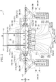
- the valve device 2 is provided with a valve casing 21, outlet valve seat portions 22, outlet valve bodies 23, an inner bar 24, outlet rod portions 25, a linkage shaft portion 26, intermediate valve seat portions 27, intermediate valve bodies 28, intermediate rod portions 29, and intermediate actuator units 30.
- the valve casing 21 in the present embodiment includes a valve casing main body 211, lateral lid portions (lid portion) 212, and an upper lid portion 213.
- valve casing main body 211 In the valve casing main body 211, inlet flow paths 51, intermediate flow paths 52, outlet flow paths 53, and external opening portions 54 are formed. In the valve casing main body 211, a space through which steam flows from the inlet flow paths 51 to the outlet flow paths 53 via the intermediate flow paths 52 is formed.
- the inlet flow paths 51 are opening portions into each of which steam flowing from an upstream side flows.
- the inlet flow paths 51 are connected to lines such as pipes connected to the steam supply source 200.
- a first inlet flow path 51a and a second inlet flow path 51b are provided as the inlet flow paths 51.
- the first inlet flow path 51a and the second inlet flow path 51b are formed to be separated from each other in a width direction (horizontal direction) Dw of the valve device 2.
- steam is supplied via two inlet flow paths 51.
- the intermediate flow paths 52 communicate with the inlet flow paths 51 and through the intermediate flow paths 52, steam flows in a direction intersecting the inlet flow paths 51.
- the intermediate flow paths 52 in the present embodiment are formed to be orthogonal to the inlet flow paths 51.
- the intermediate flow paths 52 are formed inward of the inlet flow paths 51 in the width direction Dw. Steam flowing into the intermediate flow paths 52 from the inlet flow paths 51 flows to an inner side in the width direction Dw.
- a first intermediate flow path 52a that is formed at a position close to the first inlet flow path 51a and a second intermediate flow path 52b that is formed at a position close to the second inlet flow path 51b are provided.
- the outlet flow paths 53 communicate with the intermediate flow paths 52 and through the outlet flow paths 53, and steam flows in a direction intersecting the intermediate flow paths 52.
- the outlet flow paths 53 are connected to lines such as pipes connected to the turbine main body 100.
- the outlet flow paths 53 in the present embodiment are formed to be orthogonal to the inlet flow paths 51 and the intermediate flow paths 52.
- the outlet flow paths 53 are formed inward of the intermediate flow paths 52 in the width direction Dw. Steam flowing into the outlet flow paths 53 from the intermediate flow paths 52 flows to a lower side in a vertical direction Dv.
- a plurality of the outlet flow paths 53 are provided to be separated from each other in the width direction Dw.
- a plurality of (four in present embodiment) first outlet flow paths 53a and one second outlet flow path 53b are provided as the outlet flow paths 53.
- the plurality of first outlet flow paths 53a are formed to be arranged while being separated from each other in the width direction Dw.
- the second outlet flow path 53b is formed at the center in the width direction Dw to be interposed between the first outlet flow paths 53a.
- the external opening portions 54 are formed to have a size such that the intermediate valve bodies 28, which will be described later, can be inserted thereinto.
- the external opening portions 54 are opened to communicate with the outside at positions that the intermediate flow paths 52 face.
- the external opening portions 54 in the present embodiment are formed to be orthogonal to the inlet flow paths 51 and the outlet flow paths 53.
- the external opening portions 54 are formed outward of the inlet flow paths 51 in the width direction Dw. In other words, the external opening portions 54 are formed to be opposite the intermediate flow paths 52 in the width direction Dw with the inlet flow paths 51 interposed therebetween.
- the external opening portions 54 are formed such that the positions thereof in the vertical direction Dv overlap the intermediate flow paths 52 and the inlet flow paths 51.
- a first external opening portion 54a that is formed at a position close to the first inlet flow path 51a and a second external opening portion 54b that is formed at a position close to the second inlet flow path 51b are provided.
- the first external opening portion 54a, the second external opening portion 54b, the first intermediate flow path 52a, and the second intermediate flow path 52b are formed at the same position in the vertical direction Dv.
- the lateral lid portions 212 are fixed to the valve casing main body 211 such that the external opening portions 54 are closed.
- the lateral lid portions 212 are fixed to the valve casing main body 211 by means of fixing tools such as bolts (not shown).
- the lateral lid portion 212 in the present embodiment is a disc-shaped member that is provided with a rod insertion hole 215, into which the intermediate rod portion 29 which will be described later can be inserted, formed at the center thereof.
- the lateral lid portion 212 includes a lid portion inner surface (first surface) 216 and a lid portion outer surface 217.
- the lid portion inner surface 216 is a surface that faces the intermediate flow path 52 in a state where the lateral lid portion 212 is fixed to the valve casing main body 211.
- the lid portion outer surface 217 is a surface that faces a side opposite to the lid portion inner surface 216 in the width direction Dw in a state where the lateral lid portion 212 is fixed to the valve casing main body 211. In other words, the lid portion outer surface 217 faces the outside of the valve casing 21.
- the rod insertion hole 215 penetrates from the lid portion inner surface 216 to the lid portion outer surface 217.
- the rod insertion hole 215 is formed at a position facing the intermediate valve seat portion 27, which will be described later. Note that, a member such as a guide-bush may be fitted into the rod insertion hole 215.
- a first lateral lid portion 212a that closes the first external opening portion 54a and a second lateral lid portion 212b that closes the second external opening portion 54b are provided.
- the outlet valve seat portions 22 are provided in the outlet flow paths 53.
- a plurality of the outlet valve seat portions 22 are provided to respectively correspond to the plurality of the outlet flow paths 53.
- first outlet valve seat portions 22a that are respectively provided in the first outlet flow paths 53a and a second outlet valve seat portion 22b that is provided in the second outlet flow path 53b are provided.
- the outlet valve bodies 23 come into contact with the outlet valve seat portions 22 such that the outlet flow paths 53 are closed.
- a plurality of the outlet valve bodies 23 are provided to respectively correspond to the outlet valve seat portions 22 which are provided in the plurality of outlet flow paths 53.
- first outlet valve bodies 23a that come into contact with the first outlet valve seat portions 22a and a second outlet valve body 23b that comes into contact with the second outlet valve seat portion 22b are provided.
- the first outlet valve bodies 23a can be moved upward in the vertical direction Dv while exiting a state of being in contact with the first outlet valve seat portions 22a.
- the second outlet valve body 23b can be moved upward in the vertical direction Dv while exiting a state of being in contact with the second outlet valve seat portion 22b.
- the inner bar 24 is connected to the outlet valve bodies 23 and the outlet rod portions 25.
- the inner bar 24 moves the plurality of outlet valve bodies 23 together.
- the inner bar 24 in the present embodiment holds a plurality of the first outlet valve bodies 23a and the second outlet valve body 23b.
- the inner bar 24 is formed to have a size such that the inner bar 24 can be inserted through the intermediate flow paths 52 and the external opening portions 54.
- the inner bar 24 has a thick plate-like shape that is thick in the vertical direction Dv and extends in the width direction Dw.
- the sectional area of the inner bar 24 in the vertical direction Dv is smaller than the opening areas of the external opening portions 54 and the intermediate flow paths 52.
- the outlet rod portions 25 extend along a first center axis O1. End portions of the outlet rod portions 25 that are on a first side in a first center axis direction D1 are connected to the outlet valve bodies 23.
- the first center axis direction D1 is a direction in which the first center axis O1 extends and in the present embodiment, the first center axis direction D1 is the vertical direction Dv.
- the first side in the first center axis direction D1 is a lower side in the vertical direction Dv and a second side in the first center axis direction D1 is an upper side in the vertical direction Dv.
- a plurality of (two in present embodiment) the outlet rod portions 25 are provided to be separated from each other in the width direction Dw.
- the end portions of the outlet rod portions 25 that are on a first side in the vertical direction Dv are indirectly connected to the outlet valve bodies 23 via the inner bar 24.
- the linkage shaft portion 26 linearly moves the outlet rod portions 25 in the first center axis direction D1.
- the linkage shaft portion 26 in the present embodiment moves the outlet rod portions 25 by means of a hydraulic cylinder and an E/H actuator, which use control oil, or an air cylinder, which uses steam, such that the inner bar 24 is moved in the vertical direction Dv. Accordingly, the plurality of first outlet valve bodies 23a and the second outlet valve body 23b are moved in the vertical direction Dv.
- the intermediate valve seat portions 27 are provided in the intermediate flow paths 52.
- a first intermediate valve seat portion 27a that is provided in the first intermediate flow path 52a and a second intermediate valve seat portion 27b that is provided in the second intermediate flow path 52b are provided.
- the intermediate rod portions 29 extend along a second center axis O2 that intersects the first center axis O1.
- the intermediate rod portion 29 have columnar shapes with the second center axis O2 as the center thereof. End portions of the intermediate rod portions 29 that are on a first side in a second center axis direction D2 are connected to the intermediate valve bodies 28.
- the second center axis direction D2 is a direction in which the second center axis O2 extends and in the present embodiment, the second center axis direction D2 is the width direction Dw, which is a direction orthogonal to the first center axis direction D1.
- first side in the second center axis direction D2 is an inner side in the width direction Dw and is a side at which the outlet flow paths 53 are formed, with respect to the intermediate flow paths 52.
- second sides in the first center axis direction D1 are outer sides in the width direction Dw and are sides at which the external opening portions 54 are formed, with respect to the intermediate flow paths 52.
- the intermediate rod portions 29 are inserted into the rod insertion holes 215. Outer circumferential surfaces of the intermediate rod portions 29 are disposed with gaps formed between the outer circumferential surfaces and inner circumferential surfaces of the rod insertion holes 215. End portions (base end portions 290) of the intermediate rod portions 29 that are on the outer sides in the width direction Dw are positioned outside the valve casing 21.
- End portions (tip end portions) of the intermediate rod portions 29 that are on the inner side in the width direction Dw are positioned inside the valve casing 21.
- the base end portions 290 of the intermediate rod portions 29 that are positioned outside the valve casing 21 are screw portions on which spiral grooves are formed.
- the intermediate rod portions 29 are supported by linking units 42, which will be described later, such that the intermediate rod portions 29 can be slid in the width direction Dw.
- a first intermediate rod portion 29a on the first intermediate valve seat portion 27a side and a second intermediate rod portion 29b on the second intermediate valve seat portion 27b side are provided as the intermediate rod portions 29, a first intermediate rod portion 29a on the first intermediate valve seat portion 27a side and a second intermediate rod portion 29b on the second intermediate valve seat portion 27b side are provided.
- the first intermediate rod portion 29a and the second intermediate rod portion 29b have the same shape as each other and are disposed to face opposite sides in the width direction Dw.
- the intermediate valve bodies 28 come into contact with the intermediate valve seat portions 27 such that the intermediate flow paths 52 are closed.
- the intermediate valve bodies 28 are connected to the tip end portions of the intermediate rod portions 29.
- the intermediate valve body 28 includes a slave valve body portion 61, a main valve body portion 62, and a slave valve body guide portion 63.
- the slave valve body portion 61 is fixed to the tip end portion of the intermediate rod portion 29.
- the slave valve body portion 61 has a columnar shape with the second center axis O2 as the center thereof and a tip end surface of the slave valve body portion 61 that faces the intermediate valve seat portion 27 is a spherical surface.
- the main valve body portion 62 can come into contact with the intermediate valve seat portion 27.
- the main valve body portion 62 has a disc-like shape with the second center axis O2 as the center thereof.
- the outer diameter of the main valve body portion 62 is larger than that of the slave valve body portion 61.
- the main valve body portion 62 is formed such that the outer diameter thereof decreases toward the intermediate valve seat portion 27.
- a portion of an outer circumferential surface of the main valve body portion 62 is a tapered surface that becomes closer to the second center axis O2 toward the intermediate valve seat portion 27.
- the main valve body portion 62 closes the intermediate flow path 52 by causing the tapered surface to come into contact with the intermediate valve seat portion 27.
- the accommodation space 60 is a recessed portion that is recessed from a main valve body surface 623 (surface facing external opening portion 54) that faces a side opposite to a surface of the main valve body portion 62 that faces the intermediate valve seat portion 27.
- the position of a centroid X of the main valve body portion 62 is a position that overlaps the accommodation space 60 in the width direction Dw.
- a first valve body through-hole (valve body through-hole) 621 through which the accommodation space 60 and the outlet flow paths 53 communicate with each other and a second valve body through-hole 622 through which the accommodation space 60 and the inlet flow path 51 communicate with each other are formed.
- the first valve body through-hole 621 penetrates the main valve body portion 62 such that a space connected to the outlet flow paths 53 and the accommodation space 60 communicate with each other.
- the first valve body through-hole 621 is open in a bottom surface of the recessed portion that forms the accommodation space 60.
- the first valve body through-hole 621 penetrates the main valve body portion 62 in the width direction Dw at a position facing the tip end surface of the slave valve body portion 61.
- the first valve body through-hole 621 is closed when coming into contact with the tip end surface of the slave valve body portion 61.
- the second valve body through-hole 622 penetrates the main valve body portion 62 such that a space connected to the inlet flow path 51 and the accommodation space 60 communicate with each other.
- the second valve body through-hole 622 is open in a side surface of the recessed portion that forms the accommodation space 60.
- the second valve body through-hole 622 is open in the main valve body surface 623.
- the second valve body through-hole 622 penetrates the main valve body portion 62 from the accommodation space 60 to the main valve body surface 623 while being inclined with respect to the second center axis O2.
- the second valve body through-hole 622 is formed at a position at which the second valve body through-hole 622 is in an opened state at all times regardless of the position of the slave valve body portion 61 or the main valve body portion 62.
- the slave valve body guide portion 63 guides the movement of the slave valve body portion 61 in the width direction Dw, inside the accommodation space 60.
- the slave valve body guide portion 63 is fixed to the main valve body portion 62 such that the accommodation space 60 is closed.
- the slave valve body guide portion 63 includes a slave valve body guide main body 631, a guide tubular portion 632, and a projection portion 633.
- the slave valve body guide main body 631 has a plate-like shape that extends in directions orthogonal to the intermediate rod portion 29.
- the slave valve body guide main body 631 is fixed to the main valve body portion 62 such that the accommodation space 60 is defined as a closed space.
- the slave valve body guide main body 631 is fixed to the main valve body portion 62 from a side opposite to the first valve body through-hole 621 with the accommodation space 60 interposed therebetween.
- the slave valve body guide main body 631 includes a guide front surface 631a that closes the accommodation space 60 and a guide rear surface (valve body rear surface) 631b that faces a side opposite to the guide front surface 631a in the width direction Dw.
- a valve body rod insertion hole 631c into which the intermediate rod portion 29 can be inserted is formed in the slave valve body guide main body 631.
- the valve body rod insertion hole 631c penetrates the slave valve body guide main body 631 in the width direction Dw from the guide front surface 631a to the guide rear surface 631b.
- the valve body rod insertion hole 631c is formed to have a size such that a slight gap is formed between an inner circumferential surface thereof and a side surface of the intermediate rod portion 29.
- the guide tubular portion 632 protrudes in a tubular shape from the guide front surface 631a so as to surround the valve body rod insertion hole 631c.
- the guide tubular portion 632 is disposed in the accommodation space 60 with the slave valve body guide main body 631 fixed to the main valve body portion 62.
- An inner circumferential surface of the guide tubular portion 632 is in sliding contact with an outer surface of the slave valve body portion 61.
- the guide tubular portion 632 extends up to a position such that an opening of the second valve body through-hole 622 is not closed with the slave valve body guide main body 631 fixed to the main valve body portion 62.
- the guide tubular portion 632 extends up to a position that is closer to the first valve body through-hole 621 than the position of the centroid X of the main valve body portion 62 in the second center axis direction D2.
- the projection portion 633 protrudes in a tubular shape from the guide rear surface 631b so as to surround the valve body rod insertion hole 631c.
- the projection portion 633 protrudes in the width direction Dw to a side opposite to the guide tubular portion 632 with respect to the slave valve body guide main body 631.
- a first intermediate valve body 28a and a second intermediate valve body 28b are provided as the intermediate valve bodies 28, a first intermediate valve body 28a and a second intermediate valve body 28b.
- the first intermediate valve body 28a is connected to the first intermediate rod portion 29a and comes into contact with the first intermediate valve seat portion 27a.
- the second intermediate valve body 28b is connected to the second intermediate rod portion 29b and comes into contact with the second intermediate valve seat portion 27b.
- the first intermediate valve body 28a can be moved outward in the width direction Dw while exiting a state of being in contact with the first intermediate valve seat portion 27a.
- the second intermediate valve body 28b can be moved outward in the width direction Dw while exiting a state of being in contact with the second intermediate valve seat portion 27b.
- the intermediate actuator units 30 linearly move the intermediate rod portions 29 in the second center axis direction D2.
- the intermediate actuator units 30 converts a linear motion in the first center axis direction D1 into a linear motion in the second center axis direction D2 to linearly move the intermediate rod portions 29 in the second center axis direction D2.
- the intermediate actuator units 30 in the present embodiment include a first intermediate actuator unit 30a that moves the first intermediate rod portion 29a and a second intermediate actuator unit 30b that moves the second intermediate rod portion 29b.
- Each of the first intermediate actuator unit 30a and the second intermediate actuator unit 30b includes a drive unit 41 and the linking unit 42.
- the first intermediate actuator unit 30a and the second intermediate actuator unit 30b have the same configuration as each other except for a point that directions in which the intermediate rod portions 29 are moved are opposite to each other in the second center axis direction D2 (width direction Dw). Therefore, in the present embodiment, description will be made by using the drive unit 41 and the linking unit 42 of the first intermediate actuator unit 30a as an example.
- the drive unit 41 causes a linearly moving member to advance and retreat in the vertical direction Dv, which is a direction orthogonal to the second center axis direction D2.
- the drive unit 41 in the present embodiment is a hydraulic cylinder.
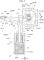
- the drive unit 41 in the embodiment includes a cylinder portion 411, a piston portion 412, a piston rod portion 413, an elastic member 414, and a rod guide portion 415.
- the cylinder portion 411 has a hollow cylindrical shape and extends in the vertical direction Dv.
- a cylinder chamber S that extends in the vertical direction Dv is formed.
- control oil is accommodated in the cylinder portion 411.
- a bottom portion of the cylinder portion 411 in the present embodiment is positioned on the lower side in the vertical direction Dv such that the piston rod portion 413 protrudes upward in the vertical direction Dv.
- the cylinder portion 411 in the present embodiment includes a cylinder main body 411a and a cylinder lid portion 411b.
- the cylinder main body 411a extends in the vertical direction Dv and has a bottomed tubular shape of which an upper side in the vertical direction Dv is open.
- the cylinder lid portion 411b is fixed to the upper side of the cylinder main body 411a in the vertical direction Dv.
- the cylinder lid portion 411b closes an open portion of the cylinder main body 411a.
- the cylinder lid portion 411b is fixed to the valve casing main body 211.
- a guide insertion hole 411c into which the rod guide portion 415, which will be described later, can be inserted is formed in the cylinder lid portion 411b.
- the guide insertion hole 411c penetrates the cylinder lid portion 411b in the vertical direction Dv.
- the piston portion 412 partitions the cylinder chamber S into a first chamber S1 that is on the upper side in the vertical direction Dv and a second chamber S2 that is on the lower side in the vertical direction Dv.
- the piston portion 412 is disposed inside the cylinder chamber S.
- the piston portion 412 moves in the vertical direction Dv.
- the entire circumference of the piston portion 412 can slide along an inner circumferential surface of the cylinder main body 411a and the position of the piston portion 412 relative to the cylinder main body 411a changes. Movement of the piston portion 412 changes the size of the first chamber S1 and the second chamber S2.
- the piston portion 412 is connected to the piston rod portion 413.
- the intermediate valve body 28 When the piston portion 412 is moved to a first side in the cylinder chamber S, the intermediate valve body 28 is moved away from the intermediate valve seat portion 27. When the piston portion 412 is moved to a second side in the cylinder chamber S, the intermediate valve body 28 is moved to be closer to the intermediate valve seat portion 27.
- the piston rod portion 413 is connected to the piston portion 412.
- the piston rod portion 413 moves along with the piston portion 412.
- the piston rod portion 413 extends from the piston portion 412 in the vertical direction Dv in a columnar shape.
- An upper end portion of the piston rod portion 413 in the vertical direction Dv which is an end portion not connected to the piston portion 412, protrudes from the cylinder portion 411.
- the piston rod portion 413 is formed to have a length such that the upper end portion in the vertical direction Dv protrudes from the cylinder portion 411 even after the piston rod portion 413 is moved downward in the vertical direction Dv.
- the elastic member 414 is disposed inside the first chamber S1.
- the elastic member 414 urges the piston portion 412 such that the piston portion 412 is pressed toward the lower side in the vertical direction Dv.
- the elastic member 414 is fixed to a surface of the cylinder lid portion 411b that faces the lower side in the vertical direction Dv and an end surface of the piston portion 412 that faces the upper side in the vertical direction Dv.
- a coil spring is used as the elastic member 414 in the present embodiment.
- the rod guide portion 415 guides movement of the piston rod portion 413 in the vertical direction Dv.
- the rod guide portion 415 has a cylindrical shape into which the piston rod portion 413 can be inserted.
- the rod guide portion 415 is fixed to the cylinder lid portion 411b.
- An outer circumferential surface of the rod guide portion 415 is in close contact with an inner circumferential surface of the guide insertion hole 411c.
- An inner circumferential surface of the rod guide portion 415 is in sliding contact with an outer circumferential surface of the piston rod portion 413.
- a gap between the inner circumferential surface of the valve body rod insertion hole 631c and the outer circumferential surface of the intermediate rod portion 29 is formed to be wider than a gap between the inner circumferential surface of the rod guide portion 415 and the outer circumferential surface of the piston rod portion 413.
- One end portion of the rod guide portion 415 is disposed to protrude upward in the vertical direction Dv with respect to a cylinder lid.
- the other end portion of the rod guide portion 415 is disposed inside the cylinder chamber S. That is, a portion of the rod guide portion 415 is disposed inside the cylinder portion 411.
- the linking unit 42 connects the intermediate rod portion 29 and the piston rod portion 413 to each other.
- the linking unit 42 converts displacement of the piston rod portion 413 in the first center axis direction D1 to displacement in the second center axis direction D2 and transmits the displacement to the intermediate rod portion 29 such that the intermediate rod portion 29 is moved in the second center axis direction D2.
- the linking unit 42 converts displacement of the piston rod portion 413 moving upward and downward in the vertical direction Dv into displacement in the width direction Dw such that the intermediate rod portion 29 is moved.
- the linking unit 42 in the present embodiment includes an intermediate rod-fixing portion 421, a first connection member 422, a second connection member 423, and a lid portion-fixing portion 424.
- the intermediate rod-fixing portion 421 is fixed to an end portion of the intermediate rod portion 29 that is not connected to the slave valve body portion 61.
- the intermediate rod-fixing portion 421 is disposed to be separated outwardly from the lateral lid portion 212 in the width direction Dw.
- the intermediate rod-fixing portion 421 has a pillar-like shape that extends in the second center axis direction D2.
- the intermediate rod-fixing portion 421 covers a part of a portion of the intermediate rod portion 29 that protrudes outward from the lateral lid portion 212 in the width direction Dw.
- a first fixation hole 421a and a second fixation hole 421b are formed in the intermediate rod-fixing portion 421.
- the first fixation hole 421a is recessed in the width direction Dw from a surface of the intermediate rod-fixing portion 421 that faces the lateral lid portion 212 side (inner side in width direction Dw). An inner circumferential surface of the first fixation hole 421a is in sliding contact with an outer circumferential surface of the intermediate rod portion 29.
- the second fixation hole 421b is further recessed in the width direction Dw from a bottom portion of the first fixation hole 421a. In other words, the second fixation hole 421b is formed at a deeper position than the first fixation hole 421a in the width direction Dw.
- the inner diameter of the second fixation hole 421b is smaller than the inner diameter of the first fixation hole 421a.
- the second fixation hole 421b is a screw hole at which the base end portion 290 of the intermediate rod portion 29 can be fixed. In other words, the base end portion 290 of the intermediate rod portion 29 is screwed into the second fixation hole 421b. In this manner, the intermediate rod-fixing portion 421 is fixed in a state of being unmovable relative to the intermediate rod portion 29.
- the first connection member 422 connects the piston rod portion 413 and the intermediate rod-fixing portion 421 to each other.
- the first connection member 422 is a planar plate member.
- the first connection member 422 is connected to the upper end portion of the piston rod portion 413 in the vertical direction Dv in a state of being rotatable.
- the first connection member 422 is connected to an outer end portion of the intermediate rod-fixing portion 421 in the width direction Dw in a state of being rotatable.
- a connection portion between the first connection member 422 and the piston rod portion 413 will be referred to as a first rotary connection portion A.
- a connection portion between the first connection member 422 and the intermediate rod-fixing portion 421 will be referred to as a second rotary connection portion B.
- the second connection member 423 connects the first connection member 422 and the lid portion-fixing portion 424 to each other.
- the second connection member 423 is a planar plate member that is shorter than the first connection member 422.
- the second connection member 423 is connected to the vicinity of an intermediate portion of the first connection member 422 in a state of being rotatable.
- the second connection member 423 is fixed to the lid portion-fixing portion 424 in a state of being rotatable.
- the lid portion-fixing portion 424 is fixed to the lateral lid portion 212 such that the lid portion-fixing portion 424 is positioned outside the valve casing 21. In other words, the second connection member 423 is fixed to the lateral lid portion 212 via the lid portion-fixing portion 424.
- a connection portion between the second connection member 423 and the first connection member 422 will be referred to as a third rotary connection portion C.
- a connection portion between the second connection member 423 and the lid portion-fixing portion 424 will be referred to as a fourth rotary connection portion D.
- the fourth rotary connection portion D is disposed at a position that overlaps the position of the first rotary connection portion A in the width direction Dw such that the fourth rotary connection portion D is disposed immediately above the piston rod portion 413 in the vertical direction Dv.
- the fourth rotary connection portion D is disposed at a position that overlaps the position of the second rotary connection portion B in the vertical direction Dv such that the fourth rotary connection portion D overlaps the intermediate rod portion 29.
- the first outlet flow paths 53a function as adjusting valves by being opened and closed by means of the first outlet valve bodies 23a, so that the amount of steam supplied to the turbine main body 100 is adjusted.
- the second outlet flow path 53b functions as an overload valve by being opened and closed by means of the second outlet valve body 23b, so that the amount of steam supplied to the turbine main body 100 is adjusted.
- the intermediate flow paths 52 function as stop valves by being opened and closed by means of the intermediate valve bodies 28, so that supply of steam to the turbine main body 100 can be stopped.
- valve device 2 configured as described above.
- the valve device 2 enters an opened state in order to cause steam to flow into the turbine main body 100 from the steam supply source 200 shown in FIG. 1 .
- the linkage shaft portion 26 shown in FIG. 2 is driven such that the outlet rod portions 25 are moved upward in the vertical direction Dv. Accordingly, the first outlet valve bodies 23a and the second outlet valve body 23b are also moved upward in the vertical direction Dv along with the inner bar 24. As a result, the first outlet valve bodies 23a are separated from the first outlet valve seat portions 22a and thus the first outlet flow paths 53a are opened. At the same time, the second outlet valve body 23b is separated from the second outlet valve seat portion 22b and thus the second outlet flow path 53b is opened.
- the linkage shaft portion 26 not only the linkage shaft portion 26 but also the intermediate actuator units 30 are driven.
- the amount of control oil is adjusted in the cylinder portions 411 shown in FIG. 5 such that the piston portions 412 are pressed by the control oil and are moved upward in the vertical direction Dv.
- the piston rod portions 413 are also moved upward in the vertical direction Dv.
- the first rotary connection portions A are moved upward in the vertical direction Dv and the first connection members 422 are moved upward in the vertical direction Dv while rotating.
- the lid portion-fixing portions 424 are fixed to the lateral lid portions 212.
- the second connection members 423 connected to the first connection members 422 rotate around the fourth rotary connection portions D with respect to the lid portion-fixing portions 424.
- the first connection members 422 are moved upward in the vertical direction Dv while rotating and the second connection members 423 rotate, the second rotary connection portions B are straightly moved outward in the width direction Dw along with the intermediate rod portions 29.
- the intermediate rod portions 29 are moved outward in the width direction Dw, the intermediate valve bodies 28 are moved to be separated from the intermediate valve seat portions 27.
- the slave valve body portions 61 connected to the intermediate rod portions 29 are moved outward in the width direction Dw to be separated from the first valve body through-holes 621.
- the outlet flow paths 53 and the inlet flow paths 51 partially communicate with each other via the first valve body through-holes 621, the accommodation spaces 60, and the second valve body through-holes 622.
- the slave valve body portions 61 come into contact with the slave valve body guide main bodies 631.
- the slave valve body guide main bodies 631 are moved outward in the width direction Dw by being pressed by the slave valve body portions 61.
- the main valve body portions 62 fixed to the slave valve body guide main bodies 631 are also moved outward in the width direction Dw. Accordingly, the main valve body portions 62 are completely separated from the intermediate valve seat portions 27 and thus the intermediate flow paths 52 are opened. Therefore, with the first intermediate actuator unit 30a being driven, the first intermediate valve body 28a is separated from the first intermediate valve seat portion 27a and thus the first intermediate flow path 52a is opened. Similarly, with the second intermediate actuator unit 30b being driven, the second intermediate valve body 28b is separated from the second intermediate valve seat portion 27b and thus the second intermediate flow path 52b is opened.
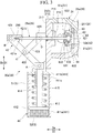
- the intermediate actuator units 30 and the linkage shaft portion 26 are driven. Specifically, contrary to the case where the intermediate flow paths 52 are to be opened, the piston portions 412 are moved downward in the vertical direction Dv. As a result, the intermediate rod portions 29 are moved inward in the width direction Dw by means of the linking units 42. When the intermediate rod portions 29 are moved inward in the width direction Dw, the intermediate valve bodies 28 are moved to become closer to the intermediate valve seat portions 27. As a result, as shown in FIG. 3 , the intermediate valve body 28 comes into contact with the intermediate valve seat portion 27 and thus the intermediate flow path 52 is closed.
- the first intermediate actuator unit 30a being driven
- the first intermediate valve body 28a comes into contact with the first intermediate valve seat portion 27a and thus the first intermediate flow path 52a is closed.
- the second intermediate actuator unit 30b being driven
- the second intermediate valve body 28b comes into contact with the second intermediate valve seat portion 27b and thus the second intermediate flow path 52b is closed.
- the linkage shaft portion 26 is driven such that the outlet rod portions 25 are moved downward in the vertical direction Dv.
- the first outlet valve bodies 23a and the second outlet valve body 23b are also moved downward in the vertical direction Dv along with the inner bar 24.
- the first outlet valve bodies 23a come into contact with the first outlet valve seat portions 22a and thus the first outlet flow paths 53a are closed.
- the second outlet valve body 23b comes into contact with the second outlet valve seat portion 22b and thus the second outlet flow path 53b is closed.
- the intermediate actuator units 30 cause the piston rod portions 413 to move in the vertical direction Dv, which is a direction orthogonal to a movement direction of the intermediate rod portions 29. Therefore, in comparison with the case where the piston rod portions 413 moving in the width direction Dw are connected to outer sides of end portions of the intermediate rod portions 29 in the width direction Dw, it is possible to suppress the size of the valve device 2 in the width direction Dw.
- the intermediate flow paths 52 are formed to be orthogonal to the outlet flow paths 53, it is possible to simplify the shape of a space inside the valve casing 21 in comparison with the case where the intermediate flow paths 52 and the outlet flow paths 53 are provided to be parallel with each other.
- the gaps between the inner circumferential surfaces of the valve body rod insertion holes 631c and the outer circumferential surfaces of the intermediate rod portions 29 are formed to be wider than the gaps between the inner circumferential surfaces of the rod guide portions 415 and the outer circumferential surfaces of the piston rod portions 413.
- the intermediate rod portions 29 are inserted into the valve body rod insertion holes 631c in a wobbling state. Therefore, movement of the intermediate rod portions 29 being impeded due to adhesion of scale is suppressed.
- valve body rod insertion holes 631c and the intermediate rod portions 29 are exposed to steam flowing in from the inlet flow paths 51. Therefore, after the steam turbine 1 is operated for a long period of time, scale generated due to steam is likely to adhere to the inner circumferential surfaces of the valve body rod insertion holes 631c or the outer circumferential surfaces of the intermediate rod portions 29.
- the gaps between the inner circumferential surfaces of the valve body rod insertion holes 631c and the outer circumferential surfaces of the intermediate rod portions 29 are excessively narrow in such a situation as in the case where the intermediate rod portions 29 are in sliding contact with the valve body rod insertion holes 631c, the gaps are clogged with scale.
- the rod guide portions 415 which guide movement of the piston rod portions 413 are provided. Therefore, it is possible to stably move the piston rod portions 413 in the vertical direction Dv with high accuracy.
- each of the piston rod portion 413 is disposed in the cylinder portion 411. Therefore, the piston rod portions 413 are exposed to control oil. As a result, control oil adheres to the outer circumferential surfaces of the piston rod portions 413 and thus sliding characteristics are significantly enhanced. Therefore, even when there is almost no gap between the inner circumferential surfaces of the rod guide portions 415 and the outer circumferential surfaces of the piston rod portions 413, a high slidability can be secured between the rod guide portions 415 and the piston rod portions 413. Accordingly, it is possible to stably move the piston rod portions 413 in the vertical direction Dv with high accuracy. As a result, it is possible to secure stable movement of the intermediate rod portions 29 or the piston rod portions 413 while securing an assembling property.
- each of the rod guide portions 415 is disposed in the cylinder portion 411. Therefore, not only the piston rod portions 413 but also the rod guide portions 415 are exposed to control oil. As a result, control oil also adheres to the inner circumferential surfaces of the rod guide portions 415. Therefore, sliding characteristics are improved not only at the outer circumferential surfaces of the piston rod portions 413 but also at the inner circumferential surfaces of the rod guide portions 415. Accordingly, significantly high slidability can be secured between the rod guide portions 415 and the piston rod portions 413. Therefore, it is possible to more stably move the piston rod portions 413 in the vertical direction Dv with high accuracy.
- the projection portions 633 protruding from the guide rear surfaces 631b come into contact with the lid portion inner surfaces 216.
- openings of the rod insertion holes 215 at the lid portion inner surfaces 216 are surrounded by the projection portions 633 brought into close contact with the lid portion inner surfaces 216 and the guide rear surfaces 631b.
- the projection portions 633 serve as sealing portions between the lateral lid portions 212 and the intermediate valve bodies 28. Accordingly, even when the intermediate flow paths 52 are opened and steam flows into the valve casing main body 211, inflow of steam into the rod insertion holes 215 can be suppressed. As a result, steam inside the valve casing main body 211 can be restrained from leaking out from the valve casing main body 211 via the rod insertion holes 215. Therefore, steam leaking into the atmosphere is reduced and it is possible to improve the efficiency of the steam turbine 1.
- the intermediate valve bodies 28 including the main valve body portions 62 are not influenced by pressure differences between sides communicating with the outlet flow paths 53 and sides communicating with the inlet flow paths 51.
- the main valve body portions 62 may be slightly inclined with respect to the slave valve body portions 61 when the slave valve body portions 61 become closer to the first valve body through-holes 621 relative to the slave valve body guide portions 63.
- the main valve body portions 62 are inclined with respect to the slave valve body portions 61 connected to the intermediate rod portions 29 even slightly, the main valve body portions 62 are inclined with respect to intermediate valve seats as well.
- the positions of the centroids X of the main valve body portions 62 overlap the slave valve body guide portions 63 in the width direction Dw. Therefore, even when the intermediate rod portions 29 are moved and the positions of the slave valve body portions 61 relative to the slave valve body guide portions 63 are shifted, the positions of the centroids X of the main valve body portions 62 in the width direction Dw do not become offset from the positions of the slave valve body guide portions 63 at all times.
- the first fixation holes 421a and the second fixation holes 421b are formed.
- the inner circumferential surfaces of the first fixation holes 421a are in sliding contact with the outer circumferential surfaces of the intermediate rod portions 29.
- the second fixation holes 421b are recessed from the bottom portions of the first fixation holes 421a and the base end portions 290 of the intermediate rod portions 29 are fixed to.
- the intermediate rod portions 29 are fixed to the second fixation holes 421b formed at deeper positions than the first fixation holes 421a in a state of being inserted into the first fixation holes 421a.
- the intermediate rod portions 29 and the piston rod portions 413 extend in the width direction Dw in a state of being connected to each other, it is possible to make the intermediate rod portions 29 the only members extending in the width direction Dw. As a result, it is possible to suppress the length of a member extending in the width direction Dw and to suppress the amount of bending caused by the gravity force. Accordingly, it becomes easy to adjust contact alignment between the intermediate valve bodies 28 and the intermediate valve seat portions 27 and thus it is possible to block main steam with high accuracy.
- the external opening portions 54 are formed outward of the intermediate flow paths 52 in the width direction Dw. Since the external opening portions 54 face the intermediate flow paths 52, when the inside of the valve casing main body 211 is seen from an outer side in the width direction Dw, a region in which the first outlet flow paths 53a and the second outlet flow path 53b are formed can be visually recognized. In other words, it is possible to easily insert a component such as the outlet valve seat portion 22 or the outlet valve body 23 into the region in which the first outlet flow paths 53a and the second outlet flow path 53b are formed via the external opening portions 54 from the outside. As a result, it is possible to improve the workability with respect to the vicinity of the outlet flow paths 53.
- the external opening portions 54 are also close to the inlet flow paths 51 and the intermediate flow paths 52, it is also possible to easily insert a component into a region in which the inlet flow paths 51 and the intermediate flow paths 52 are formed. As a result, it is possible to improve a component assembling property in the vicinity of the inlet flow paths 51 and the intermediate flow paths 52. Therefore, it is not necessary to form the inlet flow paths 51, the intermediate flow paths 52, and the outlet flow paths 53 in different casings respectively and to integrally fix the casings by means of welding or the like. Therefore, it is not necessary to secure a region for welding and it is possible to reduce the size of the valve casing 21. As a result, it is possible to further reduce the size of the valve device 2.
- one valve casing main body 211 may not be provided with the plurality of inlet flow paths 51, the plurality of intermediate flow paths 52, the plurality of outlet flow paths 53, and the plurality of external opening portions 54 as in the present embodiment.
- one valve casing main body 211 may be provided with one inlet flow path 51, one intermediate flow path 52, one outlet flow path 53, and one external opening portion 54 and may be provided with a plurality of any of the inlet flow paths 51, the intermediate flow paths 52, the outlet flow paths 53, and the external opening portions 54.
- the projection portions 633 may not be formed on the slave valve body guide portions 63 as in the present embodiment.
- the projection portions 633 only have to be formed at positions at which the projection portions 633 can come into contact with the lid portion inner surfaces 216 when the intermediate rod portions 29 are moved such that the intermediate flow paths 52 are opened.
- the projection portions 633 may be formed on the main valve body surfaces 623 (main valve body portions 62), for example.
Landscapes
- Engineering & Computer Science (AREA)
- General Engineering & Computer Science (AREA)
- Mechanical Engineering (AREA)
- Lift Valve (AREA)
- Control Of Turbines (AREA)
Abstract
Description
- The present invention relates to a valve device and a steam turbine.
- A steam turbine rotates and drives a rotor by means of steam supplied from a boiler. The steam turbine transmits the rotation of the rotor to operate a compressor or a generator.
- In the steam turbine, an adjusting valve or a stop valve is provided to supply steam from the boiler to a turbine main body. The flow rate of steam supplied to the turbine main body can be adjusted by adjusting the opening degree of the adjusting valve. In addition, at the time of a normal operation of the steam turbine, the stop valve is in an opened state. Accordingly, steam is supplied to the turbine main body from the boiler through a steam supply pipe. In addition, in the case where an abnormality occurs in the steam turbine, the stop valve enters a closed state and supply of steam from the boiler to the turbine main body is stopped.
- In Japanese Unexamined Patent Application, First Publication No.
2010-48216 - However, in such a valve device, an actuator such as a hydraulic cylinder for moving a rod (valve rod) of the main steam stop valve in the horizontal direction is provided to protrude at an outer side of the valve rod in the horizontal direction. As a result, the valve device becomes large in the horizontal direction. On the contrary, for example, in the case where a structure in which the rod of the main steam stop valve is movable in the vertical direction while being parallel to the rod of the steam-regulating valve is adopted, the shapes of a flow path of the main steam stop valve and a flow path of the steam-regulating valve, which are formed in a valve casing, become complicated by being curved a plurality of times. As a result, there is a deterioration in assembling property at the time of incorporation of a valve seat, a valve body, or the like to be disposed in the valve casing. Therefore, it is necessary to secure the assembling property by adopting a structure which is obtained by integrally fixing a valve casing of the steam-regulating valve and a valve casing of a main steam valve to each other by means of welding after creating the valve casings separately from each other, or the like.
- In addition, it is desirable that the rod be moved smoothly without use of the rod's own weight when the rod of the main steam stop valve is moved in the horizontal direction. As a structure for the above-described point, a structure in which a guide with a very narrow clearance in a direction intersecting the horizontal direction is provided with respect to the rod such that the valve rod is moved only in the horizontal direction is conceivable. However, there is a possibility that scale adheres to the rod due to the influence of steam flowing in the valve device. Therefore, there is a possibility that a region around the rod with a narrow clearance is clogged with the scale and the movement of the rod is impeded. Therefore, it is desirable to secure stable movement of the rod while securing an assembling property.
- The present invention provides a valve device and a steam turbine with which it is possible to secure stable movement of a rod while securing an assembling property.
- According to a first aspect of the present invention, a valve device is provided, including a valve casing in which an inlet flow path into which fluid is configured to flow, an intermediate flow path that communicates with the inlet flow path and through which the fluid is configured to flow in a direction intersecting the inlet flow path, and an outlet flow path that communicates with the intermediate flow path and through which the fluid is configured to flow in a direction intersecting the intermediate flow path are formed, an outlet valve seat portion provided in the outlet flow path, an outlet valve body that comes into contact with the outlet valve seat portion such that the outlet flow path is closed, an outlet rod portion that extends along a first center axis and of which an end portion on a first side in a first center axis direction is connected to the outlet valve body, a linkage shaft portion that is configured to linearly move the outlet rod portion in the first center axis direction, an intermediate valve seat portion provided in the intermediate flow path, an intermediate valve body that comes into contact with the intermediate valve seat portion such that the intermediate flow path is closed, an intermediate rod portion that extends along a second center axis intersecting the first center axis and of which an end portion on a first side in a second center axis direction is connected to the intermediate valve body, and an intermediate actuator unit that is configured to linearly move the intermediate rod portion in the second center axis direction in which the intermediate actuator unit includes a hydraulic cylinder that is configured to cause a piston rod portion to advance and retreat in a direction orthogonal to the second center axis direction, and a linking unit that connects the intermediate rod portion and the piston rod portion to each other, converts displacement of the piston rod portion into displacement in the second center axis direction, and transmits the displacement to the intermediate rod portion such that the intermediate rod portion is moved in the second center axis direction, a rod insertion hole into which the intermediate rod portion is inserted is formed in the valve casing, the hydraulic cylinder includes a cylinder portion in which control oil is accommodated, and a rod guide portion that has a tubular shape into which the piston rod portion is inserted and guides movement of the piston rod portion, and a gap between an inner circumferential surface of the rod insertion hole and an outer circumferential surface of the intermediate rod portion is formed to be wider than a gap between an inner circumferential surface of the rod guide portion and an outer circumferential surface of the piston rod portion.
- According to such a configuration, in comparison with the case where the piston rod portion moving in the second center axis direction is connected to an outer side of an end portion of the intermediate rod portion in the second center axis direction, it is possible to suppress the size of the valve device in the second center axis direction. In addition, since the intermediate flow path is formed to intersect the outlet flow path, it is possible to simplify the shape of a space inside the valve casing in comparison with the case where the intermediate flow path and the outlet flow path are provided to be parallel with each other. Therefore, it is possible to improve an assembling property at the time of incorporation of the outlet valve seat portion, the outlet valve body, or the like into the valve casing. Furthermore, the intermediate rod portion is inserted into the rod insertion hole, which is formed in a lid portion, in a wobbling state. Therefore, movement of the intermediate rod portion being impeded due to adhesion of scale is suppressed. As a result, it is possible to secure stable movement of the intermediate rod portion. Furthermore, a portion of the piston rod portion is disposed inside the cylinder portion. Therefore, the piston rod portion is exposed to the control oil. As a result, the control oil adheres to the outer circumferential surface of the piston rod portion and thus sliding characteristics are significantly enhanced. Therefore, even when there is almost no gap between the inner circumferential surface of the rod guide portion and the outer circumferential surface of the piston rod portion, high slidability can be secured between the rod guide portion and the piston rod portion. Accordingly, it is possible to stably move the piston rod portion in a vertical direction with high accuracy.
- A second aspect of the present invention provides the valve device according to the first aspect in which at least a portion of the rod guide portion may be disposed inside the cylinder portion.
- According to such a configuration, the rod guide portion is exposed to the control oil in the cylinder portion. As a result, the control oil also adheres to the inner circumferential surface of the rod guide portion. Therefore, sliding characteristics are improved not only at the outer circumferential surface of the piston rod portion but also at the inner circumferential surface of the rod guide portions. Accordingly, even when there is almost no gap between the inner circumferential surface of the rod guide portion and the outer circumferential surface of the piston rod portions, significantly high slidability can be secured between the rod guide portion and the piston rod portion. Therefore, it is possible to more stably move the piston rod portion in the vertical direction with high accuracy.
- A third aspect of the present invention provides the valve device according to the first aspect or the second aspect in which the valve casing may include a first surface in which the rod insertion hole is formed at a position facing the intermediate valve seat portion, the intermediate valve body may include a valve body rear surface that faces the first surface and to which the intermediate rod portion is connected, and a projection portion that has a tubular shape surrounding a center axis of the intermediate rod portion and protrudes toward the first surface from the valve body rear surface, and the projection portion may come into contact with the first surface when the intermediate rod portion is moved such that the intermediate flow path is opened.
- According to such a configuration, when the intermediate rod portion is moved such that the intermediate flow path is opened, an opening of the rod insertion hole at the first surface is surrounded by the projection portion brought into close contact with the first surface and the valve body rear surface. In other words, the projection portion serves as a sealing portion between the lid portion and the intermediate valve body. Accordingly, even when the intermediate flow path is opened and the fluid flows into a valve casing main body, inflow of the fluid into the rod insertion hole can be suppressed. As a result, the fluid inside the valve casing main body can be restrained from leaking out from the valve casing main body via the rod insertion hole.
- A fourth aspect of the present invention provides the valve device according to any of the first aspect to the third aspect in which the intermediate valve body may include a slave valve body portion that is fixed to a tip end of the intermediate rod portion, a main valve body portion in which an accommodation space accommodating the slave valve body portion is formed and that includes a valve body through-hole through which the accommodation space and the outlet flow path communicate with each other, and a slave valve body guide portion that is fixed to the main valve body portion and guides movement of the slave valve body portion in the accommodation space, and a centroid of the main valve body portion may be positioned to overlap the slave valve body guide portion in a movement direction of the slave valve body portion.
- According to such a configuration, the position of the centroid of the main valve body portion overlaps the slave valve body guide portion. Therefore, even when the intermediate rod portion is moved and the position of the slave valve body portion relative to the slave valve body guide portion is shifted, the position of the centroid of the main valve body portion do not become offset from the position of the slave valve body guide portion at all times. In other words, a state where the slave valve body portion is stably supported with respect to the slave valve body guide portion can be maintained. As a result, it is possible to prevent the main valve body portion from being inclined with respect to the slave valve body portion. Accordingly, it is possible to stably close the intermediate flow path by means of the intermediate valve body.
- A fifth aspect of the present invention provides the valve device according to any of the first aspect to the fourth aspect in which the linking unit may include an intermediate rod-fixing portion to which the intermediate rod portion is fixed, and the intermediate rod-fixing portion may include a first fixation hole that is formed such that an inner circumferential surface thereof comes into sliding contact with the outer circumferential surface of the intermediate rod portion, and a second fixation hole that is recessed from a bottom portion of the first fixation hole and to which a base end portion of the intermediate rod portion is fixed.
- According to such a configuration, the intermediate rod portion is fixed to the second fixation hole formed at a deeper position than the first fixation hole in a state of being inserted into the first fixation hole. Therefore, even if the base end portion of the intermediate rod portion is broken or the like and the base end portion of the intermediate rod portion and the second fixation hole fixed to each other are released from each other, the intermediate rod portion remains inserted into the first fixation hole. Therefore, the intermediate rod portion is restrained from falling out from the intermediate rod-fixing portion.
- According to a sixth aspect of the present invention, a steam turbine is provided, including the valve device according to any one of the first aspect to the fifth aspect and a turbine main body that is driven by means of steam supplied from the valve device.
- According to the present invention, it is possible to secure stable movement of a rod while securing an assembling property.
-
-
FIG. 1 is a schematic view illustrating the entire configuration of a steam turbine configured by using a stop valve according to an embodiment of the present invention. -
FIG. 2 is a schematic sectional view illustrating a valve device according to the embodiment of the present invention. -
FIG. 3 is a main part enlarged view showing a fully closed state of the valve device according to the embodiment. -
FIG. 4 is a main part enlarged view of the vicinity of an outlet valve body according to the embodiment. -
FIG. 5 is a main part enlarged view showing a fully-opened state of the valve device according to the embodiment. - Hereinafter, an embodiment of the present invention will be described with reference to
FIGS. 1 to 5 . - As shown in
FIG. 1 , asteam turbine 1 according to the present embodiment is provided with a turbinemain body 100 and avalve device 2. - Steam (fluid) is supplied to the turbine
main body 100 from asteam supply source 200 such as a boiler. In the turbinemain body 100, a rotor (not shown) that is rotatably provided in a casing (not shown) is rotated and driven by the supplied steam. The rotation of the rotor (not shown) is transmitted to, for example, a generator via an output shaft, so that power is generated. - The
valve device 2 is a composite valve obtained by integrating an adjusting valve (governing valve: GV), a stop valve (trip valve: TV), and an overload valve with each other. Thevalve device 2 is provided on the side of an inlet of the turbinemain body 100 and adjusts the amount of steam supplied to the turbinemain body 100. As shown inFIG. 2 , thevalve device 2 is provided with avalve casing 21, outletvalve seat portions 22,outlet valve bodies 23, aninner bar 24,outlet rod portions 25, alinkage shaft portion 26, intermediatevalve seat portions 27,intermediate valve bodies 28,intermediate rod portions 29, andintermediate actuator units 30. - Inside the
valve casing 21, a space serving as a flow path through which steam flows is formed. Thevalve casing 21 in the present embodiment includes a valve casingmain body 211, lateral lid portions (lid portion) 212, and anupper lid portion 213. - In the valve casing
main body 211,inlet flow paths 51,intermediate flow paths 52,outlet flow paths 53, andexternal opening portions 54 are formed. In the valve casingmain body 211, a space through which steam flows from theinlet flow paths 51 to theoutlet flow paths 53 via theintermediate flow paths 52 is formed. - The
inlet flow paths 51 are opening portions into each of which steam flowing from an upstream side flows. Theinlet flow paths 51 are connected to lines such as pipes connected to thesteam supply source 200. In the present embodiment, as theinlet flow paths 51, a firstinlet flow path 51a and a secondinlet flow path 51b are provided. The firstinlet flow path 51a and the secondinlet flow path 51b are formed to be separated from each other in a width direction (horizontal direction) Dw of thevalve device 2. In other words, to thevalve device 2 in the present embodiment, steam is supplied via twoinlet flow paths 51. - The
intermediate flow paths 52 communicate with theinlet flow paths 51 and through theintermediate flow paths 52, steam flows in a direction intersecting theinlet flow paths 51. Theintermediate flow paths 52 in the present embodiment are formed to be orthogonal to theinlet flow paths 51. Theintermediate flow paths 52 are formed inward of theinlet flow paths 51 in the width direction Dw. Steam flowing into theintermediate flow paths 52 from theinlet flow paths 51 flows to an inner side in the width direction Dw. In the present embodiment, as theintermediate flow paths 52, a firstintermediate flow path 52a that is formed at a position close to the firstinlet flow path 51a and a secondintermediate flow path 52b that is formed at a position close to the secondinlet flow path 51b are provided. - The
outlet flow paths 53 communicate with theintermediate flow paths 52 and through theoutlet flow paths 53, and steam flows in a direction intersecting theintermediate flow paths 52. Theoutlet flow paths 53 are connected to lines such as pipes connected to the turbinemain body 100. Theoutlet flow paths 53 in the present embodiment are formed to be orthogonal to theinlet flow paths 51 and theintermediate flow paths 52. Theoutlet flow paths 53 are formed inward of theintermediate flow paths 52 in the width direction Dw. Steam flowing into theoutlet flow paths 53 from theintermediate flow paths 52 flows to a lower side in a vertical direction Dv. A plurality of theoutlet flow paths 53 are provided to be separated from each other in the width direction Dw. In the present embodiment, as theoutlet flow paths 53, a plurality of (four in present embodiment) firstoutlet flow paths 53a and one secondoutlet flow path 53b are provided. - The plurality of first
outlet flow paths 53a are formed to be arranged while being separated from each other in the width direction Dw. The secondoutlet flow path 53b is formed at the center in the width direction Dw to be interposed between the firstoutlet flow paths 53a. - The
external opening portions 54 are formed to have a size such that theintermediate valve bodies 28, which will be described later, can be inserted thereinto. Theexternal opening portions 54 are opened to communicate with the outside at positions that theintermediate flow paths 52 face. Theexternal opening portions 54 in the present embodiment are formed to be orthogonal to theinlet flow paths 51 and theoutlet flow paths 53. Theexternal opening portions 54 are formed outward of theinlet flow paths 51 in the width direction Dw. In other words, theexternal opening portions 54 are formed to be opposite theintermediate flow paths 52 in the width direction Dw with theinlet flow paths 51 interposed therebetween. Theexternal opening portions 54 are formed such that the positions thereof in the vertical direction Dv overlap theintermediate flow paths 52 and theinlet flow paths 51. In the present embodiment, as theexternal opening portions 54, a firstexternal opening portion 54a that is formed at a position close to the firstinlet flow path 51a and a secondexternal opening portion 54b that is formed at a position close to the secondinlet flow path 51b are provided. The firstexternal opening portion 54a, the secondexternal opening portion 54b, the firstintermediate flow path 52a, and the secondintermediate flow path 52b are formed at the same position in the vertical direction Dv. As a result, when the inside of the valve casingmain body 211 is seen from the outside, the firstexternal opening portion 54a and the secondexternal opening portion 54b communicate with each other straightly in the width direction Dw. - The
lateral lid portions 212 are fixed to the valve casingmain body 211 such that theexternal opening portions 54 are closed. Thelateral lid portions 212 are fixed to the valve casingmain body 211 by means of fixing tools such as bolts (not shown). As shown inFIG. 3 , thelateral lid portion 212 in the present embodiment is a disc-shaped member that is provided with arod insertion hole 215, into which theintermediate rod portion 29 which will be described later can be inserted, formed at the center thereof. Thelateral lid portion 212 includes a lid portion inner surface (first surface) 216 and a lid portionouter surface 217. The lid portioninner surface 216 is a surface that faces theintermediate flow path 52 in a state where thelateral lid portion 212 is fixed to the valve casingmain body 211. The lid portionouter surface 217 is a surface that faces a side opposite to the lid portioninner surface 216 in the width direction Dw in a state where thelateral lid portion 212 is fixed to the valve casingmain body 211. In other words, the lid portionouter surface 217 faces the outside of thevalve casing 21. Therod insertion hole 215 penetrates from the lid portioninner surface 216 to the lid portionouter surface 217. Therod insertion hole 215 is formed at a position facing the intermediatevalve seat portion 27, which will be described later. Note that, a member such as a guide-bush may be fitted into therod insertion hole 215. In the present embodiment, as thelateral lid portions 212, a firstlateral lid portion 212a that closes the firstexternal opening portion 54a and a secondlateral lid portion 212b that closes the secondexternal opening portion 54b are provided. - The outlet
valve seat portions 22 are provided in theoutlet flow paths 53. A plurality of the outletvalve seat portions 22 are provided to respectively correspond to the plurality of theoutlet flow paths 53. In the present embodiment, as the outletvalve seat portions 22, first outletvalve seat portions 22a that are respectively provided in the firstoutlet flow paths 53a and a second outletvalve seat portion 22b that is provided in the secondoutlet flow path 53b are provided. - The
outlet valve bodies 23 come into contact with the outletvalve seat portions 22 such that theoutlet flow paths 53 are closed. A plurality of theoutlet valve bodies 23 are provided to respectively correspond to the outletvalve seat portions 22 which are provided in the plurality ofoutlet flow paths 53. In the present embodiment, as theoutlet valve bodies 23, firstoutlet valve bodies 23a that come into contact with the first outletvalve seat portions 22a and a secondoutlet valve body 23b that comes into contact with the second outletvalve seat portion 22b are provided. The firstoutlet valve bodies 23a can be moved upward in the vertical direction Dv while exiting a state of being in contact with the first outletvalve seat portions 22a. The secondoutlet valve body 23b can be moved upward in the vertical direction Dv while exiting a state of being in contact with the second outletvalve seat portion 22b. - The
inner bar 24 is connected to theoutlet valve bodies 23 and theoutlet rod portions 25. Theinner bar 24 moves the plurality ofoutlet valve bodies 23 together. Theinner bar 24 in the present embodiment holds a plurality of the firstoutlet valve bodies 23a and the secondoutlet valve body 23b. Theinner bar 24 is formed to have a size such that theinner bar 24 can be inserted through theintermediate flow paths 52 and theexternal opening portions 54. Specifically, theinner bar 24 has a thick plate-like shape that is thick in the vertical direction Dv and extends in the width direction Dw. The sectional area of theinner bar 24 in the vertical direction Dv is smaller than the opening areas of theexternal opening portions 54 and theintermediate flow paths 52. - The
outlet rod portions 25 extend along a first center axis O1. End portions of theoutlet rod portions 25 that are on a first side in a first center axis direction D1 are connected to theoutlet valve bodies 23. Here, the first center axis direction D1 is a direction in which the first center axis O1 extends and in the present embodiment, the first center axis direction D1 is the vertical direction Dv. In addition, the first side in the first center axis direction D1 is a lower side in the vertical direction Dv and a second side in the first center axis direction D1 is an upper side in the vertical direction Dv. In the present embodiment, a plurality of (two in present embodiment) theoutlet rod portions 25 are provided to be separated from each other in the width direction Dw. The end portions of theoutlet rod portions 25 that are on a first side in the vertical direction Dv are indirectly connected to theoutlet valve bodies 23 via theinner bar 24. - The
linkage shaft portion 26 linearly moves theoutlet rod portions 25 in the first center axis direction D1. Thelinkage shaft portion 26 in the present embodiment moves theoutlet rod portions 25 by means of a hydraulic cylinder and an E/H actuator, which use control oil, or an air cylinder, which uses steam, such that theinner bar 24 is moved in the vertical direction Dv. Accordingly, the plurality of firstoutlet valve bodies 23a and the secondoutlet valve body 23b are moved in the vertical direction Dv. - The intermediate
valve seat portions 27 are provided in theintermediate flow paths 52. In the present embodiment, as the intermediatevalve seat portions 27, a first intermediatevalve seat portion 27a that is provided in the firstintermediate flow path 52a and a second intermediatevalve seat portion 27b that is provided in the secondintermediate flow path 52b are provided. - The
intermediate rod portions 29 extend along a second center axis O2 that intersects the first center axis O1. Theintermediate rod portion 29 have columnar shapes with the second center axis O2 as the center thereof. End portions of theintermediate rod portions 29 that are on a first side in a second center axis direction D2 are connected to theintermediate valve bodies 28. Here, the second center axis direction D2 is a direction in which the second center axis O2 extends and in the present embodiment, the second center axis direction D2 is the width direction Dw, which is a direction orthogonal to the first center axis direction D1. In addition, the first side in the second center axis direction D2 is an inner side in the width direction Dw and is a side at which theoutlet flow paths 53 are formed, with respect to theintermediate flow paths 52. In addition, second sides in the first center axis direction D1 are outer sides in the width direction Dw and are sides at which theexternal opening portions 54 are formed, with respect to theintermediate flow paths 52. Theintermediate rod portions 29 are inserted into the rod insertion holes 215. Outer circumferential surfaces of theintermediate rod portions 29 are disposed with gaps formed between the outer circumferential surfaces and inner circumferential surfaces of the rod insertion holes 215. End portions (base end portions 290) of theintermediate rod portions 29 that are on the outer sides in the width direction Dw are positioned outside thevalve casing 21. End portions (tip end portions) of theintermediate rod portions 29 that are on the inner side in the width direction Dw are positioned inside thevalve casing 21. Thebase end portions 290 of theintermediate rod portions 29 that are positioned outside thevalve casing 21 are screw portions on which spiral grooves are formed. Theintermediate rod portions 29 are supported by linkingunits 42, which will be described later, such that theintermediate rod portions 29 can be slid in the width direction Dw. In the present embodiment, as theintermediate rod portions 29, a firstintermediate rod portion 29a on the first intermediatevalve seat portion 27a side and a second intermediate rod portion 29b on the second intermediatevalve seat portion 27b side are provided. The firstintermediate rod portion 29a and the second intermediate rod portion 29b have the same shape as each other and are disposed to face opposite sides in the width direction Dw. - The
intermediate valve bodies 28 come into contact with the intermediatevalve seat portions 27 such that theintermediate flow paths 52 are closed. Theintermediate valve bodies 28 are connected to the tip end portions of theintermediate rod portions 29. As shown inFIG. 4 , theintermediate valve body 28 includes a slavevalve body portion 61, a mainvalve body portion 62, and a slave valvebody guide portion 63. - The slave
valve body portion 61 is fixed to the tip end portion of theintermediate rod portion 29. The slavevalve body portion 61 has a columnar shape with the second center axis O2 as the center thereof and a tip end surface of the slavevalve body portion 61 that faces the intermediatevalve seat portion 27 is a spherical surface. - The main
valve body portion 62 can come into contact with the intermediatevalve seat portion 27. The mainvalve body portion 62 has a disc-like shape with the second center axis O2 as the center thereof. The outer diameter of the mainvalve body portion 62 is larger than that of the slavevalve body portion 61. The mainvalve body portion 62 is formed such that the outer diameter thereof decreases toward the intermediatevalve seat portion 27. Specifically, a portion of an outer circumferential surface of the mainvalve body portion 62 is a tapered surface that becomes closer to the second center axis O2 toward the intermediatevalve seat portion 27. The mainvalve body portion 62 closes theintermediate flow path 52 by causing the tapered surface to come into contact with the intermediatevalve seat portion 27. Inside the mainvalve body portion 62, anaccommodation space 60 in which the slavevalve body portion 61 can be accommodated is formed. Theaccommodation space 60 is a recessed portion that is recessed from a main valve body surface 623 (surface facing external opening portion 54) that faces a side opposite to a surface of the mainvalve body portion 62 that faces the intermediatevalve seat portion 27. The position of a centroid X of the mainvalve body portion 62 is a position that overlaps theaccommodation space 60 in the width direction Dw. In the mainvalve body portion 62, a first valve body through-hole (valve body through-hole) 621 through which theaccommodation space 60 and theoutlet flow paths 53 communicate with each other and a second valve body through-hole 622 through which theaccommodation space 60 and theinlet flow path 51 communicate with each other are formed. - The first valve body through-
hole 621 penetrates the mainvalve body portion 62 such that a space connected to theoutlet flow paths 53 and theaccommodation space 60 communicate with each other. The first valve body through-hole 621 is open in a bottom surface of the recessed portion that forms theaccommodation space 60. Specifically, the first valve body through-hole 621 penetrates the mainvalve body portion 62 in the width direction Dw at a position facing the tip end surface of the slavevalve body portion 61. The first valve body through-hole 621 is closed when coming into contact with the tip end surface of the slavevalve body portion 61. - The second valve body through-
hole 622 penetrates the mainvalve body portion 62 such that a space connected to theinlet flow path 51 and theaccommodation space 60 communicate with each other. The second valve body through-hole 622 is open in a side surface of the recessed portion that forms theaccommodation space 60. The second valve body through-hole 622 is open in the mainvalve body surface 623. The second valve body through-hole 622 penetrates the mainvalve body portion 62 from theaccommodation space 60 to the mainvalve body surface 623 while being inclined with respect to the second center axis O2. The second valve body through-hole 622 is formed at a position at which the second valve body through-hole 622 is in an opened state at all times regardless of the position of the slavevalve body portion 61 or the mainvalve body portion 62. - The slave valve
body guide portion 63 guides the movement of the slavevalve body portion 61 in the width direction Dw, inside theaccommodation space 60. The slave valvebody guide portion 63 is fixed to the mainvalve body portion 62 such that theaccommodation space 60 is closed. The slave valvebody guide portion 63 includes a slave valve body guidemain body 631, a guidetubular portion 632, and aprojection portion 633. - The slave valve body guide
main body 631 has a plate-like shape that extends in directions orthogonal to theintermediate rod portion 29. The slave valve body guidemain body 631 is fixed to the mainvalve body portion 62 such that theaccommodation space 60 is defined as a closed space. The slave valve body guidemain body 631 is fixed to the mainvalve body portion 62 from a side opposite to the first valve body through-hole 621 with theaccommodation space 60 interposed therebetween. The slave valve body guidemain body 631 includes aguide front surface 631a that closes theaccommodation space 60 and a guide rear surface (valve body rear surface) 631b that faces a side opposite to theguide front surface 631a in the width direction Dw. In the slave valve body guidemain body 631, a valve bodyrod insertion hole 631c into which theintermediate rod portion 29 can be inserted is formed. The valve bodyrod insertion hole 631c penetrates the slave valve body guidemain body 631 in the width direction Dw from theguide front surface 631a to the guiderear surface 631b. The valve bodyrod insertion hole 631c is formed to have a size such that a slight gap is formed between an inner circumferential surface thereof and a side surface of theintermediate rod portion 29. - The guide
tubular portion 632 protrudes in a tubular shape from theguide front surface 631a so as to surround the valve bodyrod insertion hole 631c. The guidetubular portion 632 is disposed in theaccommodation space 60 with the slave valve body guidemain body 631 fixed to the mainvalve body portion 62. An inner circumferential surface of the guidetubular portion 632 is in sliding contact with an outer surface of the slavevalve body portion 61. The guidetubular portion 632 extends up to a position such that an opening of the second valve body through-hole 622 is not closed with the slave valve body guidemain body 631 fixed to the mainvalve body portion 62. The guidetubular portion 632 extends up to a position that is closer to the first valve body through-hole 621 than the position of the centroid X of the mainvalve body portion 62 in the second center axis direction D2. - The
projection portion 633 protrudes in a tubular shape from the guiderear surface 631b so as to surround the valve bodyrod insertion hole 631c. Theprojection portion 633 protrudes in the width direction Dw to a side opposite to the guidetubular portion 632 with respect to the slave valve body guidemain body 631. - In the present embodiment, as the
intermediate valve bodies 28, a firstintermediate valve body 28a and a secondintermediate valve body 28b are provided. The firstintermediate valve body 28a is connected to the firstintermediate rod portion 29a and comes into contact with the first intermediatevalve seat portion 27a. The secondintermediate valve body 28b is connected to the second intermediate rod portion 29b and comes into contact with the second intermediatevalve seat portion 27b. The firstintermediate valve body 28a can be moved outward in the width direction Dw while exiting a state of being in contact with the first intermediatevalve seat portion 27a. The secondintermediate valve body 28b can be moved outward in the width direction Dw while exiting a state of being in contact with the second intermediatevalve seat portion 27b. - The
intermediate actuator units 30 linearly move theintermediate rod portions 29 in the second center axis direction D2. Theintermediate actuator units 30 converts a linear motion in the first center axis direction D1 into a linear motion in the second center axis direction D2 to linearly move theintermediate rod portions 29 in the second center axis direction D2. Theintermediate actuator units 30 in the present embodiment include a firstintermediate actuator unit 30a that moves the firstintermediate rod portion 29a and a secondintermediate actuator unit 30b that moves the second intermediate rod portion 29b. Each of the firstintermediate actuator unit 30a and the secondintermediate actuator unit 30b includes adrive unit 41 and the linkingunit 42. - The first
intermediate actuator unit 30a and the secondintermediate actuator unit 30b have the same configuration as each other except for a point that directions in which theintermediate rod portions 29 are moved are opposite to each other in the second center axis direction D2 (width direction Dw). Therefore, in the present embodiment, description will be made by using thedrive unit 41 and the linkingunit 42 of the firstintermediate actuator unit 30a as an example. - As shown in
FIG. 3 , thedrive unit 41 causes a linearly moving member to advance and retreat in the vertical direction Dv, which is a direction orthogonal to the second center axis direction D2. Thedrive unit 41 in the present embodiment is a hydraulic cylinder. Thedrive unit 41 in the embodiment includes acylinder portion 411, apiston portion 412, apiston rod portion 413, anelastic member 414, and arod guide portion 415. - The
cylinder portion 411 has a hollow cylindrical shape and extends in the vertical direction Dv. In thecylinder portion 411, a cylinder chamber S that extends in the vertical direction Dv is formed. In thecylinder portion 411, control oil is accommodated. A bottom portion of thecylinder portion 411 in the present embodiment is positioned on the lower side in the vertical direction Dv such that thepiston rod portion 413 protrudes upward in the vertical direction Dv. - The
cylinder portion 411 in the present embodiment includes a cylindermain body 411a and acylinder lid portion 411b. The cylindermain body 411a extends in the vertical direction Dv and has a bottomed tubular shape of which an upper side in the vertical direction Dv is open. Thecylinder lid portion 411b is fixed to the upper side of the cylindermain body 411a in the vertical direction Dv. Thecylinder lid portion 411b closes an open portion of the cylindermain body 411a. Thecylinder lid portion 411b is fixed to the valve casingmain body 211. In thecylinder lid portion 411b, aguide insertion hole 411c into which therod guide portion 415, which will be described later, can be inserted is formed. Theguide insertion hole 411c penetrates thecylinder lid portion 411b in the vertical direction Dv. - The
piston portion 412 partitions the cylinder chamber S into a first chamber S1 that is on the upper side in the vertical direction Dv and a second chamber S2 that is on the lower side in the vertical direction Dv. Thepiston portion 412 is disposed inside the cylinder chamber S. Thepiston portion 412 moves in the vertical direction Dv. The entire circumference of thepiston portion 412 can slide along an inner circumferential surface of the cylindermain body 411a and the position of thepiston portion 412 relative to the cylindermain body 411a changes. Movement of thepiston portion 412 changes the size of the first chamber S1 and the second chamber S2. Thepiston portion 412 is connected to thepiston rod portion 413. When thepiston portion 412 is moved to a first side in the cylinder chamber S, theintermediate valve body 28 is moved away from the intermediatevalve seat portion 27. When thepiston portion 412 is moved to a second side in the cylinder chamber S, theintermediate valve body 28 is moved to be closer to the intermediatevalve seat portion 27. - The
piston rod portion 413 is connected to thepiston portion 412. Thepiston rod portion 413 moves along with thepiston portion 412. Thepiston rod portion 413 extends from thepiston portion 412 in the vertical direction Dv in a columnar shape. An upper end portion of thepiston rod portion 413 in the vertical direction Dv, which is an end portion not connected to thepiston portion 412, protrudes from thecylinder portion 411. Thepiston rod portion 413 is formed to have a length such that the upper end portion in the vertical direction Dv protrudes from thecylinder portion 411 even after thepiston rod portion 413 is moved downward in the vertical direction Dv. - The
elastic member 414 is disposed inside the first chamber S1. Theelastic member 414 urges thepiston portion 412 such that thepiston portion 412 is pressed toward the lower side in the vertical direction Dv. Theelastic member 414 is fixed to a surface of thecylinder lid portion 411b that faces the lower side in the vertical direction Dv and an end surface of thepiston portion 412 that faces the upper side in the vertical direction Dv. As theelastic member 414 in the present embodiment, for example, a coil spring is used. - The
rod guide portion 415 guides movement of thepiston rod portion 413 in the vertical direction Dv. Therod guide portion 415 has a cylindrical shape into which thepiston rod portion 413 can be inserted. Therod guide portion 415 is fixed to thecylinder lid portion 411b. An outer circumferential surface of therod guide portion 415 is in close contact with an inner circumferential surface of theguide insertion hole 411c. An inner circumferential surface of therod guide portion 415 is in sliding contact with an outer circumferential surface of thepiston rod portion 413. A gap between the inner circumferential surface of the valve bodyrod insertion hole 631c and the outer circumferential surface of theintermediate rod portion 29 is formed to be wider than a gap between the inner circumferential surface of therod guide portion 415 and the outer circumferential surface of thepiston rod portion 413. One end portion of therod guide portion 415 is disposed to protrude upward in the vertical direction Dv with respect to a cylinder lid. The other end portion of therod guide portion 415 is disposed inside the cylinder chamber S. That is, a portion of therod guide portion 415 is disposed inside thecylinder portion 411. - The linking
unit 42 connects theintermediate rod portion 29 and thepiston rod portion 413 to each other. The linkingunit 42 converts displacement of thepiston rod portion 413 in the first center axis direction D1 to displacement in the second center axis direction D2 and transmits the displacement to theintermediate rod portion 29 such that theintermediate rod portion 29 is moved in the second center axis direction D2. In other words, the linkingunit 42 converts displacement of thepiston rod portion 413 moving upward and downward in the vertical direction Dv into displacement in the width direction Dw such that theintermediate rod portion 29 is moved. The linkingunit 42 in the present embodiment includes an intermediate rod-fixingportion 421, afirst connection member 422, asecond connection member 423, and a lid portion-fixingportion 424. - The intermediate rod-fixing
portion 421 is fixed to an end portion of theintermediate rod portion 29 that is not connected to the slavevalve body portion 61. The intermediate rod-fixingportion 421 is disposed to be separated outwardly from thelateral lid portion 212 in the width direction Dw. The intermediate rod-fixingportion 421 has a pillar-like shape that extends in the second center axis direction D2. The intermediate rod-fixingportion 421 covers a part of a portion of theintermediate rod portion 29 that protrudes outward from thelateral lid portion 212 in the width direction Dw. In the intermediate rod-fixingportion 421, afirst fixation hole 421a and asecond fixation hole 421b are formed. - The
first fixation hole 421a is recessed in the width direction Dw from a surface of the intermediate rod-fixingportion 421 that faces thelateral lid portion 212 side (inner side in width direction Dw). An inner circumferential surface of thefirst fixation hole 421a is in sliding contact with an outer circumferential surface of theintermediate rod portion 29. - The
second fixation hole 421b is further recessed in the width direction Dw from a bottom portion of thefirst fixation hole 421a. In other words, thesecond fixation hole 421b is formed at a deeper position than thefirst fixation hole 421a in the width direction Dw. The inner diameter of thesecond fixation hole 421b is smaller than the inner diameter of thefirst fixation hole 421a. Thesecond fixation hole 421b is a screw hole at which thebase end portion 290 of theintermediate rod portion 29 can be fixed. In other words, thebase end portion 290 of theintermediate rod portion 29 is screwed into thesecond fixation hole 421b. In this manner, the intermediate rod-fixingportion 421 is fixed in a state of being unmovable relative to theintermediate rod portion 29. - The
first connection member 422 connects thepiston rod portion 413 and the intermediate rod-fixingportion 421 to each other. Thefirst connection member 422 is a planar plate member. Thefirst connection member 422 is connected to the upper end portion of thepiston rod portion 413 in the vertical direction Dv in a state of being rotatable. Thefirst connection member 422 is connected to an outer end portion of the intermediate rod-fixingportion 421 in the width direction Dw in a state of being rotatable. Here, a connection portion between thefirst connection member 422 and thepiston rod portion 413 will be referred to as a first rotary connection portion A. In addition, a connection portion between thefirst connection member 422 and the intermediate rod-fixingportion 421 will be referred to as a second rotary connection portion B. - The
second connection member 423 connects thefirst connection member 422 and the lid portion-fixingportion 424 to each other. Thesecond connection member 423 is a planar plate member that is shorter than thefirst connection member 422. Thesecond connection member 423 is connected to the vicinity of an intermediate portion of thefirst connection member 422 in a state of being rotatable. Thesecond connection member 423 is fixed to the lid portion-fixingportion 424 in a state of being rotatable. The lid portion-fixingportion 424 is fixed to thelateral lid portion 212 such that the lid portion-fixingportion 424 is positioned outside thevalve casing 21. In other words, thesecond connection member 423 is fixed to thelateral lid portion 212 via the lid portion-fixingportion 424. Here, a connection portion between thesecond connection member 423 and thefirst connection member 422 will be referred to as a third rotary connection portion C. In addition, a connection portion between thesecond connection member 423 and the lid portion-fixingportion 424 will be referred to as a fourth rotary connection portion D. Regarding the position of the fourth rotary connection portion D in the width direction Dw, the fourth rotary connection portion D is disposed at a position that overlaps the position of the first rotary connection portion A in the width direction Dw such that the fourth rotary connection portion D is disposed immediately above thepiston rod portion 413 in the vertical direction Dv. Regarding the position of the fourth rotary connection portion D in the vertical direction Dv, the fourth rotary connection portion D is disposed at a position that overlaps the position of the second rotary connection portion B in the vertical direction Dv such that the fourth rotary connection portion D overlaps theintermediate rod portion 29. - As shown in
FIG. 2 , in thevalve device 2 according to the present embodiment, the firstoutlet flow paths 53a function as adjusting valves by being opened and closed by means of the firstoutlet valve bodies 23a, so that the amount of steam supplied to the turbinemain body 100 is adjusted. In addition, in thevalve device 2, the secondoutlet flow path 53b functions as an overload valve by being opened and closed by means of the secondoutlet valve body 23b, so that the amount of steam supplied to the turbinemain body 100 is adjusted. In addition, in thevalve device 2, theintermediate flow paths 52 function as stop valves by being opened and closed by means of theintermediate valve bodies 28, so that supply of steam to the turbinemain body 100 can be stopped. - Next, the operation of the
valve device 2 configured as described above will be described. In the case of thesteam turbine 1 as described above, at the time of a normal operation, thevalve device 2 enters an opened state in order to cause steam to flow into the turbinemain body 100 from thesteam supply source 200 shown inFIG. 1 . - In the case where the
valve device 2 is in an opened state, thelinkage shaft portion 26 shown inFIG. 2 is driven such that theoutlet rod portions 25 are moved upward in the vertical direction Dv. Accordingly, the firstoutlet valve bodies 23a and the secondoutlet valve body 23b are also moved upward in the vertical direction Dv along with theinner bar 24. As a result, the firstoutlet valve bodies 23a are separated from the first outletvalve seat portions 22a and thus the firstoutlet flow paths 53a are opened. At the same time, the secondoutlet valve body 23b is separated from the second outletvalve seat portion 22b and thus the secondoutlet flow path 53b is opened. - Furthermore, not only the
linkage shaft portion 26 but also theintermediate actuator units 30 are driven. Specifically, the amount of control oil is adjusted in thecylinder portions 411 shown inFIG. 5 such that thepiston portions 412 are pressed by the control oil and are moved upward in the vertical direction Dv. When thepiston portions 412 are moved, thepiston rod portions 413 are also moved upward in the vertical direction Dv. When thepiston rod portions 413 are moved, the first rotary connection portions A are moved upward in the vertical direction Dv and thefirst connection members 422 are moved upward in the vertical direction Dv while rotating. At this time, the lid portion-fixingportions 424 are fixed to thelateral lid portions 212. Therefore, thesecond connection members 423 connected to thefirst connection members 422 rotate around the fourth rotary connection portions D with respect to the lid portion-fixingportions 424. When thefirst connection members 422 are moved upward in the vertical direction Dv while rotating and thesecond connection members 423 rotate, the second rotary connection portions B are straightly moved outward in the width direction Dw along with theintermediate rod portions 29. When theintermediate rod portions 29 are moved outward in the width direction Dw, theintermediate valve bodies 28 are moved to be separated from the intermediatevalve seat portions 27. - Specifically, first, the slave
valve body portions 61 connected to theintermediate rod portions 29 are moved outward in the width direction Dw to be separated from the first valve body through-holes 621. As a result, theoutlet flow paths 53 and theinlet flow paths 51 partially communicate with each other via the first valve body through-holes 621, theaccommodation spaces 60, and the second valve body through-holes 622. When theintermediate rod portions 29 are further moved outward in the width direction Dw in this state, the slavevalve body portions 61 come into contact with the slave valve body guidemain bodies 631. When theintermediate rod portions 29 are further moved outward in the width direction Dw, the slave valve body guidemain bodies 631 are moved outward in the width direction Dw by being pressed by the slavevalve body portions 61. As a result, the mainvalve body portions 62 fixed to the slave valve body guidemain bodies 631 are also moved outward in the width direction Dw. Accordingly, the mainvalve body portions 62 are completely separated from the intermediatevalve seat portions 27 and thus theintermediate flow paths 52 are opened. Therefore, with the firstintermediate actuator unit 30a being driven, the firstintermediate valve body 28a is separated from the first intermediatevalve seat portion 27a and thus the firstintermediate flow path 52a is opened. Similarly, with the secondintermediate actuator unit 30b being driven, the secondintermediate valve body 28b is separated from the second intermediatevalve seat portion 27b and thus the secondintermediate flow path 52b is opened. - In addition, in the case where the amount of steam supplied to the turbine
main body 100 is to be reduced at the time of a normal operation, only thelinkage shaft portion 26 shown inFIG. 2 is driven such that theoutlet rod portions 25 are moved downward in the vertical direction Dv. Accordingly, the firstoutlet valve bodies 23a become closer to the first outletvalve seat portions 22a and thus the opening amounts of the firstoutlet flow paths 53a are reduced. At the same time, the secondoutlet valve body 23b becomes closer to the second outletvalve seat portion 22b and thus the opening amount of the secondoutlet flow path 53b is reduced. - At the time of emergency stoppage of the turbine
main body 100 which is made when there is an abnormality in the turbinemain body 100, theintermediate actuator units 30 and thelinkage shaft portion 26 are driven. Specifically, contrary to the case where theintermediate flow paths 52 are to be opened, thepiston portions 412 are moved downward in the vertical direction Dv. As a result, theintermediate rod portions 29 are moved inward in the width direction Dw by means of the linkingunits 42. When theintermediate rod portions 29 are moved inward in the width direction Dw, theintermediate valve bodies 28 are moved to become closer to the intermediatevalve seat portions 27. As a result, as shown inFIG. 3 , theintermediate valve body 28 comes into contact with the intermediatevalve seat portion 27 and thus theintermediate flow path 52 is closed. Therefore, with the firstintermediate actuator unit 30a being driven, the firstintermediate valve body 28a comes into contact with the first intermediatevalve seat portion 27a and thus the firstintermediate flow path 52a is closed. Similarly, with the secondintermediate actuator unit 30b being driven, the secondintermediate valve body 28b comes into contact with the second intermediatevalve seat portion 27b and thus the secondintermediate flow path 52b is closed. At the same time, thelinkage shaft portion 26 is driven such that theoutlet rod portions 25 are moved downward in the vertical direction Dv. Accordingly, the firstoutlet valve bodies 23a and the secondoutlet valve body 23b are also moved downward in the vertical direction Dv along with theinner bar 24. As a result, the firstoutlet valve bodies 23a come into contact with the first outletvalve seat portions 22a and thus the firstoutlet flow paths 53a are closed. At the same time, the secondoutlet valve body 23b comes into contact with the second outletvalve seat portion 22b and thus the secondoutlet flow path 53b is closed. - According to the
valve device 2 as described above, theintermediate actuator units 30 cause thepiston rod portions 413 to move in the vertical direction Dv, which is a direction orthogonal to a movement direction of theintermediate rod portions 29. Therefore, in comparison with the case where thepiston rod portions 413 moving in the width direction Dw are connected to outer sides of end portions of theintermediate rod portions 29 in the width direction Dw, it is possible to suppress the size of thevalve device 2 in the width direction Dw. In addition, since theintermediate flow paths 52 are formed to be orthogonal to theoutlet flow paths 53, it is possible to simplify the shape of a space inside thevalve casing 21 in comparison with the case where theintermediate flow paths 52 and theoutlet flow paths 53 are provided to be parallel with each other. Therefore, it is possible to improve an assembling property at the time of incorporation of the outletvalve seat portions 22, theoutlet valve bodies 23, or the like into thevalve casing 21. As a result, it is possible to achieve reduction in size of thevalve device 2 while securing an assembling property. Accordingly, it is possible to achieve reduction in size of theentire steam turbine 1. - In addition, the gaps between the inner circumferential surfaces of the valve body rod insertion holes 631c and the outer circumferential surfaces of the
intermediate rod portions 29 are formed to be wider than the gaps between the inner circumferential surfaces of therod guide portions 415 and the outer circumferential surfaces of thepiston rod portions 413. In other words, theintermediate rod portions 29 are inserted into the valve body rod insertion holes 631c in a wobbling state. Therefore, movement of theintermediate rod portions 29 being impeded due to adhesion of scale is suppressed. - Specifically, the valve body rod insertion holes 631c and the
intermediate rod portions 29 are exposed to steam flowing in from theinlet flow paths 51. Therefore, after thesteam turbine 1 is operated for a long period of time, scale generated due to steam is likely to adhere to the inner circumferential surfaces of the valve body rod insertion holes 631c or the outer circumferential surfaces of theintermediate rod portions 29. When gaps between the inner circumferential surfaces of the valve body rod insertion holes 631c and the outer circumferential surfaces of theintermediate rod portions 29 are excessively narrow in such a situation as in the case where theintermediate rod portions 29 are in sliding contact with the valve bodyrod insertion holes 631c, the gaps are clogged with scale. When the gaps are clogged with scale, movement of theintermediate rod portions 29 relative to the valve bodyrod insertion holes 631c is hindered. However, in the case where the gaps between the inner circumferential surfaces of the valve body rod insertion holes 631c and the outer circumferential surfaces of theintermediate rod portions 29 are widened, there is no portion that guides movement of theintermediate rod portions 29. As a result, it becomes difficult to move theintermediate rod portions 29 in the width direction Dw with high accuracy. With regard to this, in the present embodiment, therod guide portions 415 which guide movement of thepiston rod portions 413 are provided. Therefore, it is possible to stably move thepiston rod portions 413 in the vertical direction Dv with high accuracy. Since thepiston rod portions 413 are moved with high accuracy, it is possible to move theintermediate rod portions 29 in the width direction Dw with high accuracy without providing a structure for directly guiding movement of theintermediate rod portions 29. Accordingly, it is possible to secure movement of theintermediate rod portions 29 with high accuracy without being influenced by scale. - Furthermore, a portion of each of the
piston rod portion 413 is disposed in thecylinder portion 411. Therefore, thepiston rod portions 413 are exposed to control oil. As a result, control oil adheres to the outer circumferential surfaces of thepiston rod portions 413 and thus sliding characteristics are significantly enhanced. Therefore, even when there is almost no gap between the inner circumferential surfaces of therod guide portions 415 and the outer circumferential surfaces of thepiston rod portions 413, a high slidability can be secured between therod guide portions 415 and thepiston rod portions 413. Accordingly, it is possible to stably move thepiston rod portions 413 in the vertical direction Dv with high accuracy. As a result, it is possible to secure stable movement of theintermediate rod portions 29 or thepiston rod portions 413 while securing an assembling property. - In addition, in the present embodiment, a portion of each of the
rod guide portions 415 is disposed in thecylinder portion 411. Therefore, not only thepiston rod portions 413 but also therod guide portions 415 are exposed to control oil. As a result, control oil also adheres to the inner circumferential surfaces of therod guide portions 415. Therefore, sliding characteristics are improved not only at the outer circumferential surfaces of thepiston rod portions 413 but also at the inner circumferential surfaces of therod guide portions 415. Accordingly, significantly high slidability can be secured between therod guide portions 415 and thepiston rod portions 413. Therefore, it is possible to more stably move thepiston rod portions 413 in the vertical direction Dv with high accuracy. - In addition, when the
intermediate rod portions 29 are moved outward in the width direction Dw such that theintermediate flow paths 52 are opened, theprojection portions 633 protruding from the guiderear surfaces 631b come into contact with the lid portion inner surfaces 216. As a result, openings of the rod insertion holes 215 at the lid portioninner surfaces 216 are surrounded by theprojection portions 633 brought into close contact with the lid portioninner surfaces 216 and the guiderear surfaces 631b. In other words, theprojection portions 633 serve as sealing portions between thelateral lid portions 212 and theintermediate valve bodies 28. Accordingly, even when theintermediate flow paths 52 are opened and steam flows into the valve casingmain body 211, inflow of steam into the rod insertion holes 215 can be suppressed. As a result, steam inside the valve casingmain body 211 can be restrained from leaking out from the valve casingmain body 211 via the rod insertion holes 215. Therefore, steam leaking into the atmosphere is reduced and it is possible to improve the efficiency of thesteam turbine 1. - In addition, as shown in
FIG. 3 , in a state where theintermediate flow path 52 is closed by theintermediate valve body 28, a pressure difference is generated in the slavevalve body portion 61 between the first valve body through-hole 621 side (side communicating with outlet flow path 53) and theaccommodation space 60 side (side communicating with inlet flow path 51). Due to the pressure difference, a thrust force toward the inner side in the width direction Dw acts on the slavevalve body portion 61 such that the slavevalve body portion 61 is pressed against the first valve body through-hole 621. Therefore, when theintermediate rod portions 29 are to be moved outward in the width direction Dw such that theintermediate flow paths 52 are opened, theintermediate rod portions 29 are moved after forces against the thrust forces acting on the slavevalve body portions 61 are applied first. When theintermediate rod portions 29 are moved and the slavevalve body portions 61 are moved, the closed first valve body through-holes 621 are opened. As a result, theaccommodation spaces 60 communicate with theoutlet flow paths 53. Theaccommodation spaces 60 also communicate with theinlet flow paths 51 via the second valve body through-holes 622. Therefore, when the first valve body through-holes 621 are opened, theintermediate valve bodies 28 including the mainvalve body portions 62 are not influenced by pressure differences between sides communicating with theoutlet flow paths 53 and sides communicating with theinlet flow paths 51. As a result, it is possible to move theintermediate rod portions 29 outward in the width direction Dw with a significantly small force in comparison with the case where each of theintermediate valve bodies 28 is simply formed by using a large single member of the mainvalve body portion 62. Therefore, a force necessary for movement of theintermediate rod portions 29 can be suppressed and thus thedrive units 41 can have small-size structures. - In addition, in the case where the position of the centroid X of each main
valve body portion 62 in the width direction Dw is shifted to be closer to the first valve body through-hole 621 side than the slave valvebody guide portion 63, the mainvalve body portions 62 may be slightly inclined with respect to the slavevalve body portions 61 when the slavevalve body portions 61 become closer to the first valve body through-holes 621 relative to the slave valvebody guide portions 63. When the mainvalve body portions 62 are inclined with respect to the slavevalve body portions 61 connected to theintermediate rod portions 29 even slightly, the mainvalve body portions 62 are inclined with respect to intermediate valve seats as well. As a result, even when the mainvalve body portions 62 are brought into close contact with the intermediate valve seats to close theintermediate flow paths 52, there is a possibility that gaps are generated between the mainvalve body portions 62 and the intermediate valve seats and theintermediate flow paths 52 cannot be completely closed. With regard to this, in the present embodiment, the positions of the centroids X of the mainvalve body portions 62 overlap the slave valvebody guide portions 63 in the width direction Dw. Therefore, even when theintermediate rod portions 29 are moved and the positions of the slavevalve body portions 61 relative to the slave valvebody guide portions 63 are shifted, the positions of the centroids X of the mainvalve body portions 62 in the width direction Dw do not become offset from the positions of the slave valvebody guide portions 63 at all times. In other words, a state where the slavevalve body portions 61 are stably supported with respect to the slave valvebody guide portions 63 can be maintained. As a result, it is possible to prevent the mainvalve body portions 62 from being inclined with respect to the slavevalve body portions 61. Accordingly, it is possible to stably close theintermediate flow paths 52 by means of theintermediate valve bodies 28. - In addition, in the intermediate rod-fixing
portions 421, thefirst fixation holes 421a and the second fixation holes 421b are formed. The inner circumferential surfaces of thefirst fixation holes 421a are in sliding contact with the outer circumferential surfaces of theintermediate rod portions 29. The second fixation holes 421b are recessed from the bottom portions of thefirst fixation holes 421a and thebase end portions 290 of theintermediate rod portions 29 are fixed to. In other words, theintermediate rod portions 29 are fixed to the second fixation holes 421b formed at deeper positions than thefirst fixation holes 421a in a state of being inserted into thefirst fixation holes 421a. Therefore, even if thebase end portions 290 of theintermediate rod portions 29 are broken or the like and thebase end portions 290 of theintermediate rod portions 29 and the second fixation holes 421b fixed to each other are released from each other, theintermediate rod portions 29 remain inserted into thefirst fixation holes 421a. Therefore, theintermediate rod portions 29 are restrained from falling out from the intermediate rod-fixingportions 421. As a result, even when theintermediate rod portions 29 and the intermediate rod-fixingportions 421 fixed to each other are released from each other, it is possible to press theintermediate rod portions 29 inward in the width direction Dw by moving the intermediate rod-fixingportions 421 inward in the width direction Dw. Accordingly, it is possible to close theintermediate flow paths 52 and thus it is possible to secure the reliability of thevalve device 2. - In addition, unlike the case where the
intermediate rod portions 29 and thepiston rod portions 413 extend in the width direction Dw in a state of being connected to each other, it is possible to make theintermediate rod portions 29 the only members extending in the width direction Dw. As a result, it is possible to suppress the length of a member extending in the width direction Dw and to suppress the amount of bending caused by the gravity force. Accordingly, it becomes easy to adjust contact alignment between theintermediate valve bodies 28 and the intermediatevalve seat portions 27 and thus it is possible to block main steam with high accuracy. - In addition, in the valve casing
main body 211, theexternal opening portions 54 are formed outward of theintermediate flow paths 52 in the width direction Dw. Since theexternal opening portions 54 face theintermediate flow paths 52, when the inside of the valve casingmain body 211 is seen from an outer side in the width direction Dw, a region in which the firstoutlet flow paths 53a and the secondoutlet flow path 53b are formed can be visually recognized. In other words, it is possible to easily insert a component such as the outletvalve seat portion 22 or theoutlet valve body 23 into the region in which the firstoutlet flow paths 53a and the secondoutlet flow path 53b are formed via theexternal opening portions 54 from the outside. As a result, it is possible to improve the workability with respect to the vicinity of theoutlet flow paths 53. In addition, since theexternal opening portions 54 are also close to theinlet flow paths 51 and theintermediate flow paths 52, it is also possible to easily insert a component into a region in which theinlet flow paths 51 and theintermediate flow paths 52 are formed. As a result, it is possible to improve a component assembling property in the vicinity of theinlet flow paths 51 and theintermediate flow paths 52. Therefore, it is not necessary to form theinlet flow paths 51, theintermediate flow paths 52, and theoutlet flow paths 53 in different casings respectively and to integrally fix the casings by means of welding or the like. Therefore, it is not necessary to secure a region for welding and it is possible to reduce the size of thevalve casing 21. As a result, it is possible to further reduce the size of thevalve device 2. - While preferred embodiments of the invention have been described and illustrated above, it should be understood that these are exemplary of the invention and are not to be considered as limiting. Additions, omissions, substitutions, and other modifications can be made without departing from the spirit or scope of the present invention. Accordingly, the invention is not to be considered as being limited by the foregoing description, and is only limited by the scope of the appended claims.
- Note that, one valve casing
main body 211 may not be provided with the plurality ofinlet flow paths 51, the plurality ofintermediate flow paths 52, the plurality ofoutlet flow paths 53, and the plurality ofexternal opening portions 54 as in the present embodiment. For example, one valve casingmain body 211 may be provided with oneinlet flow path 51, oneintermediate flow path 52, oneoutlet flow path 53, and oneexternal opening portion 54 and may be provided with a plurality of any of theinlet flow paths 51, theintermediate flow paths 52, theoutlet flow paths 53, and theexternal opening portions 54. - In addition, the
projection portions 633 may not be formed on the slave valvebody guide portions 63 as in the present embodiment. Theprojection portions 633 only have to be formed at positions at which theprojection portions 633 can come into contact with the lid portioninner surfaces 216 when theintermediate rod portions 29 are moved such that theintermediate flow paths 52 are opened. Theprojection portions 633 may be formed on the main valve body surfaces 623 (main valve body portions 62), for example. - According to the present invention, it is possible to secure stable movement of a rod while securing an assembling property.
-
- 1
- steam turbine
- 100
- turbine main body
- 200
- steam supply source
- 2
- valve device
- Dw
- width direction
- Dv
- vertical direction
- D1
- first center axis direction
- D2
- second center axis direction
- 21
- valve casing
- 211
- valve casing main body
- 51
- inlet flow path
- 51a
- first inlet flow path
- 51b
- second inlet flow path
- 52
- intermediate flow path
- 52a
- first intermediate flow path
- 52b
- second intermediate flow path
- 53
- outlet flow path
- 53a
- first outlet flow path
- 53b
- second outlet flow path
- 54
- external opening portion
- 54a
- first external opening portion
- 54b
- second external opening portion
- 212
- lateral lid portion
- 215
- rod insertion hole
- 216
- lid portion inner surface
- 217
- lid portion outer surface
- 212a
- first lateral lid portion
- 212b
- second lateral lid portion
- 213
- upper lid portion
- 22
- outlet valve seat portion
- 22a
- first outlet valve seat portion
- 22b
- second outlet valve seat portion
- 23
- outlet valve body
- 23a
- first outlet valve body
- 23b
- second outlet valve body
- 24
- inner bar
- 25
- outlet rod portion
- O1
- first center axis
- 26
- linkage shaft portion
- 27
- intermediate valve seat portion
- 27a
- first intermediate valve seat portion
- 27b
- second intermediate valve seat portion
- 28
- intermediate valve body
- 61
- slave valve body portion
- 62
- main valve body portion
- 60
- accommodation space
- 621
- first valve body through-hole
- 622
- second valve body through-hole
- 623
- main valve body surface
- X
- centroid
- 63
- slave valve body guide portion
- 631
- slave valve body guide main body
- 631a
- guide front surface
- 631b
- guide rear surface
- 631c
- valve body rod insertion hole
- 632
- guide tubular portion
- 633
- projection portion
- 28a
- first intermediate valve body
- 28b
- second intermediate valve body
- 29
- intermediate rod portion
- O2
- second center axis
- 29a
- first intermediate rod portion
- 29b
- second intermediate rod portion
- 290
- base end portion
- 30
- intermediate actuator unit
- 30a
- first intermediate actuator unit
- 30b
- second intermediate actuator unit
- 41
- drive unit
- 411
- cylinder portion
- S
- cylinder chamber
- S1
- first chamber
- S2
- second chamber
- 411a
- cylinder main body
- 411b
- cylinder lid portion
- 411c
- guide insertion hole
- 412
- piston portion
- 413
- piston rod portion
- 414
- elastic member
- 415
- rod guide portion
- 42
- linking unit
- 421
- intermediate rod-fixing portion
- 421a
- first fixation hole
- 421b
- second fixation hole
- 422
- first connection member
- 423
- second connection member
- 424
- lid portion-fixing portion
- A
- first rotary connection portion
- B
- second rotary connection portion
- C
- third rotary connection portion
- D
- fourth rotary connection portion
Claims (6)
- A valve device comprising:a valve casing in which an inlet flow path into which fluid is configured to flow, an intermediate flow path that communicates with the inlet flow path and through which the fluid is configured to flow in a direction intersecting the inlet flow path, and an outlet flow path that communicates with the intermediate flow path and through which the fluid is configured to flow in a direction intersecting the intermediate flow path are formed;an outlet valve seat portion provided in the outlet flow path;an outlet valve body that comes into contact with the outlet valve seat portion such that the outlet flow path is closed;an outlet rod portion that extends along a first center axis and of which an end portion on a first side in a first center axis direction is connected to the outlet valve body;a linkage shaft portion that is configured to linearly move the outlet rod portion in the first center axis direction;an intermediate valve seat portion provided in the intermediate flow path;an intermediate valve body that comes into contact with the intermediate valve seat portion such that the intermediate flow path is closed;an intermediate rod portion that extends along a second center axis intersecting the first center axis and of which an end portion on a first side in a second center axis direction is connected to the intermediate valve body; andan intermediate actuator unit that is configured to linearly move the intermediate rod portion in the second center axis direction,wherein the intermediate actuator unit includesa hydraulic cylinder that configured to cause a piston rod portion to advance and retreat in a direction orthogonal to the second center axis direction, anda linking unit that connects the intermediate rod portion and the piston rod portion to each other, converts displacement of the piston rod portion into displacement in the second center axis direction, and transmits the displacement to the intermediate rod portion such that the intermediate rod portion is moved in the second center axis direction,wherein a rod insertion hole into which the intermediate rod portion is inserted is formed in the valve casing,wherein the hydraulic cylinder includesa cylinder portion in which control oil is accommodated, anda rod guide portion that has a tubular shape into which the piston rod portion is inserted and guides movement of the piston rod portion, andwherein a gap between an inner circumferential surface of the rod insertion hole and an outer circumferential surface of the intermediate rod portion is formed to be wider than a gap between an inner circumferential surface of the rod guide portion and an outer circumferential surface of the piston rod portion.
- The valve device according to claim 1,
wherein at least a portion of the rod guide portion is disposed inside the cylinder portion. - The valve device according to claim 1 or 2,wherein the valve casing includes a first surface in which the rod insertion hole is formed at a position facing the intermediate valve seat portion,wherein the intermediate valve body includesa valve body rear surface that faces the first surface and to which the intermediate rod portion is connected, anda projection portion that has a tubular shape surrounding a center axis of the intermediate rod portion and protrudes toward the first surface from the valve body rear surface, andwherein the projection portion comes into contact with the first surface when the intermediate rod portion is moved such that the intermediate flow path is opened.
- The valve device according to any one of claims 1 to 3,wherein the intermediate valve body includesa slave valve body portion that is fixed to a tip end of the intermediate rod portion,a main valve body portion in which an accommodation space accommodating the slave valve body portion is formed and that includes a valve body through-hole through which the accommodation space and the outlet flow path communicate with each other, anda slave valve body guide portion that is fixed to the main valve body portion and guides movement of the slave valve body portion in the accommodation space, andwherein a centroid of the main valve body portion is positioned to overlap the slave valve body guide portion in a movement direction of the slave valve body portion.
- The valve device according to any one of claims 1 to 4,wherein the linking unit includes an intermediate rod-fixing portion to which the intermediate rod portion is fixed, andwherein the intermediate rod-fixing portion includesa first fixation hole that is formed such that an inner circumferential surface thereof comes into sliding contact with the outer circumferential surface of the intermediate rod portion, anda second fixation hole that is recessed from a bottom portion of the first fixation hole and to which a base end portion of the intermediate rod portion is fixed.
- A steam turbine comprising:the valve device according to any one of claims 1 to 5; anda turbine main body that is driven by means of steam supplied from the valve device.
Applications Claiming Priority (1)
| Application Number | Priority Date | Filing Date | Title |
|---|---|---|---|
| JP2019031740A JP7216567B2 (en) | 2019-02-25 | 2019-02-25 | valve gear and steam turbine |
Publications (2)
| Publication Number | Publication Date |
|---|---|
| EP3699402A1 true EP3699402A1 (en) | 2020-08-26 |
| EP3699402B1 EP3699402B1 (en) | 2023-03-29 |
Family
ID=69845018
Family Applications (1)
| Application Number | Title | Priority Date | Filing Date |
|---|---|---|---|
| EP20158206.1A Active EP3699402B1 (en) | 2019-02-25 | 2020-02-19 | Valve device and steam turbine |
Country Status (4)
| Country | Link |
|---|---|
| US (1) | US11415018B2 (en) |
| EP (1) | EP3699402B1 (en) |
| JP (1) | JP7216567B2 (en) |
| CN (1) | CN111608742B (en) |
Families Citing this family (2)
| Publication number | Priority date | Publication date | Assignee | Title |
|---|---|---|---|---|
| JP7417511B2 (en) * | 2020-12-16 | 2024-01-18 | 三菱重工コンプレッサ株式会社 | Valve gear and steam turbine |
| CN217815326U (en) * | 2022-08-16 | 2022-11-15 | 华能(福建漳州)能源有限责任公司 | High-reliability temperature and pressure reducer |
Citations (4)
| Publication number | Priority date | Publication date | Assignee | Title |
|---|---|---|---|---|
| JP2010048216A (en) | 2008-08-25 | 2010-03-04 | Fuji Electric Systems Co Ltd | Main steam inlet part of steam turbine |
| EP2937520A1 (en) * | 2012-12-21 | 2015-10-28 | Mitsubishi Hitachi Power Systems, Ltd. | Steam valve and steam turbine |
| EP2952692A1 (en) * | 2013-03-27 | 2015-12-09 | Mitsubishi Heavy Industries Compressor Corporation | Multi-valve-type steam valve and steam turbine |
| EP2990611A1 (en) * | 2014-02-19 | 2016-03-02 | Mitsubishi Heavy Industries Compressor Corporation | Vapor valve and vapor turbine |
Family Cites Families (34)
| Publication number | Priority date | Publication date | Assignee | Title |
|---|---|---|---|---|
| US2192193A (en) * | 1937-01-29 | 1940-03-05 | Arthur J Johnson | Valve |
| US2147874A (en) * | 1937-10-19 | 1939-02-21 | Westinghouse Electric & Mfg Co | Elastic fluid turbine |
| US2385537A (en) * | 1942-12-17 | 1945-09-25 | Westinghouse Electric Corp | Valve operating mechanism |
| DE1915267B2 (en) * | 1969-03-26 | 1971-05-06 | Siemens AG, 1000 Berlin u 8000 München | INPUT BOX FOR NOZZLE GROUP CONTROL OF STEAM TURBINES |
| US3703183A (en) * | 1971-02-11 | 1972-11-21 | Carrier Corp | Turbine speed control |
| US3763894A (en) * | 1971-06-16 | 1973-10-09 | Westinghouse Electric Corp | Sequentially operable control valve for a steam turbine |
| GB1453251A (en) * | 1973-01-25 | 1976-10-20 | Deinlein Kalb J A F | Conbined starting and rapid shut-off valve for a steam or gas turbine |
| US4245162A (en) * | 1973-08-15 | 1981-01-13 | Westinghouse Electric Corp. | Steam turbine power plant having improved testing method and system for turbine inlet valves associated with downstream inlet valves preferably having feedforward position managed control |
| US4235416A (en) * | 1978-11-08 | 1980-11-25 | Westinghouse Electric Corp. | Vibration resistant valve |
| US4456032A (en) * | 1982-01-18 | 1984-06-26 | Elliott Turbomachinery Company, Inc. | Fluid admission valve structure |
| US4850793A (en) * | 1987-10-13 | 1989-07-25 | Westinghouse Electric Corp. | Steam chest modifications for improved turbine operations |
| US5277403A (en) * | 1993-05-12 | 1994-01-11 | Dresser-Rand Company | Balanced, steam control valve assembly, and a plug-type valving element therefor |
| JPH09105311A (en) * | 1995-10-11 | 1997-04-22 | Fuji Electric Co Ltd | Steam turbine steam control valve |
| US5823742A (en) * | 1995-12-15 | 1998-10-20 | Dresser-Rand Company | Variable and bidirectional steam flow apparatus and method |
| US6099246A (en) * | 1998-01-27 | 2000-08-08 | Siemens Aktiengesellschaft | Admission section of a turbine casing |
| JP2002097903A (en) * | 2000-09-27 | 2002-04-05 | Mitsubishi Heavy Ind Ltd | Steam valve |
| JP4230751B2 (en) | 2002-10-29 | 2009-02-25 | 株式会社東芝 | Steam valve |
| US7604021B2 (en) * | 2002-10-29 | 2009-10-20 | Kabushiki Kaisha Toshiba | Steam valve |
| JP5967973B2 (en) * | 2012-02-27 | 2016-08-10 | 三菱日立パワーシステムズ株式会社 | Check valve |
| US20140054477A1 (en) | 2012-08-27 | 2014-02-27 | Ross Arthur Schade | Axial fluid valves with annular flow control members |
| JP6076823B2 (en) * | 2013-04-26 | 2017-02-08 | 株式会社東芝 | Steam valve device |
| JP2015081568A (en) * | 2013-10-23 | 2015-04-27 | 株式会社東芝 | Steam valve device |
| JP6382556B2 (en) * | 2014-04-08 | 2018-08-29 | 株式会社東芝 | Steam valve |
| JP2016109054A (en) * | 2014-12-08 | 2016-06-20 | 三菱重工業株式会社 | Valve gear and steam turbine |
| JP6474662B2 (en) * | 2015-03-26 | 2019-02-27 | 三菱日立パワーシステムズ株式会社 | Steam valve device |
| JP6657250B2 (en) * | 2015-04-03 | 2020-03-04 | ターボデン ソシエタ ペル アツィオーニTurboden Spa | Multi-stage turbine, preferably for an organic Rankine cycle ORC plant |
| WO2017072880A1 (en) * | 2015-10-28 | 2017-05-04 | 三菱重工コンプレッサ株式会社 | Valve device and steam turbine equipment |
| WO2017104035A1 (en) * | 2015-12-17 | 2017-06-22 | 三菱重工コンプレッサ株式会社 | Main stop valve, and steam turbine provided with same |
| CN205605941U (en) * | 2016-05-03 | 2016-09-28 | 锦州新锦化机械制造有限公司 | Long -range oily accuse formula steam turbine stop valve controlling means |
| KR101642675B1 (en) * | 2016-05-09 | 2016-07-26 | 김성동 | Portable pipe bending device using hydraulic pressure |
| JP6713826B2 (en) * | 2016-05-20 | 2020-06-24 | 三菱日立パワーシステムズ株式会社 | Parent-child valve, its closing method, and steam turbine equipment |
| JP2018172976A (en) * | 2017-03-31 | 2018-11-08 | 三菱重工コンプレッサ株式会社 | Steam valve |
| JP6946154B2 (en) * | 2017-11-17 | 2021-10-06 | 三菱重工コンプレッサ株式会社 | Valve gear and steam turbine |
| JP7026520B2 (en) * | 2018-01-30 | 2022-02-28 | 三菱重工コンプレッサ株式会社 | Valve gears for turbines, turbines, and how to make them |
-
2019
- 2019-02-25 JP JP2019031740A patent/JP7216567B2/en active Active
-
2020
- 2020-02-19 US US16/794,465 patent/US11415018B2/en active Active
- 2020-02-19 EP EP20158206.1A patent/EP3699402B1/en active Active
- 2020-02-21 CN CN202010110399.4A patent/CN111608742B/en active Active
Patent Citations (4)
| Publication number | Priority date | Publication date | Assignee | Title |
|---|---|---|---|---|
| JP2010048216A (en) | 2008-08-25 | 2010-03-04 | Fuji Electric Systems Co Ltd | Main steam inlet part of steam turbine |
| EP2937520A1 (en) * | 2012-12-21 | 2015-10-28 | Mitsubishi Hitachi Power Systems, Ltd. | Steam valve and steam turbine |
| EP2952692A1 (en) * | 2013-03-27 | 2015-12-09 | Mitsubishi Heavy Industries Compressor Corporation | Multi-valve-type steam valve and steam turbine |
| EP2990611A1 (en) * | 2014-02-19 | 2016-03-02 | Mitsubishi Heavy Industries Compressor Corporation | Vapor valve and vapor turbine |
Also Published As
| Publication number | Publication date |
|---|---|
| JP2020133586A (en) | 2020-08-31 |
| US20200271009A1 (en) | 2020-08-27 |
| EP3699402B1 (en) | 2023-03-29 |
| JP7216567B2 (en) | 2023-02-01 |
| CN111608742A (en) | 2020-09-01 |
| US11415018B2 (en) | 2022-08-16 |
| CN111608742B (en) | 2022-06-28 |
Similar Documents
| Publication | Publication Date | Title |
|---|---|---|
| EP3699402B1 (en) | Valve device and steam turbine | |
| KR102356392B1 (en) | electronic expansion valve | |
| US11543044B2 (en) | Stepper motor driven proportional rotary actuator | |
| US8820356B2 (en) | Multi-way reversing valve | |
| EP3467336B1 (en) | Rotary damper | |
| US9212608B2 (en) | Low friction fuel metering valve | |
| CN103672136B (en) | Axial fluid valve with annularly flow control element | |
| MX2007010487A (en) | Fluid flow control valve with high temperature bi-directional shutoff. | |
| US7963185B2 (en) | Stepper motor driven proportional actuator | |
| EP2508782A1 (en) | Check valve | |
| KR20120135466A (en) | Pressure independent control valve | |
| CN113586793A (en) | Axial-flow control valve with gear rack transmission belt pre-tightening valve seat structure | |
| US20080078459A1 (en) | Rotary hydraulic damper for check valve | |
| EP3486434B1 (en) | Steam turbine valve device and steam turbine | |
| CN107076177B (en) | hydraulic axis | |
| EP3301308B1 (en) | Integrated hydraulic rotary actuator | |
| EP3797214B1 (en) | Simplified mechanism for a scotch yoke actuator | |
| EP3673179B1 (en) | Actuator bearing arrangement | |
| RU2298716C2 (en) | Safety make-up sectional valve | |
| CN100406717C (en) | Governors and control valves for water turbines, etc. | |
| CN120212299A (en) | A control valve | |
| UA13939U (en) | Controlling disc valve with unloading unit | |
| PL219381B1 (en) | Radial hydrostatic bearing |
Legal Events
| Date | Code | Title | Description |
|---|---|---|---|
| PUAI | Public reference made under article 153(3) epc to a published international application that has entered the european phase |
Free format text: ORIGINAL CODE: 0009012 |
|
| STAA | Information on the status of an ep patent application or granted ep patent |
Free format text: STATUS: THE APPLICATION HAS BEEN PUBLISHED |
|
| AK | Designated contracting states |
Kind code of ref document: A1 Designated state(s): AL AT BE BG CH CY CZ DE DK EE ES FI FR GB GR HR HU IE IS IT LI LT LU LV MC MK MT NL NO PL PT RO RS SE SI SK SM TR |
|
| AX | Request for extension of the european patent |
Extension state: BA ME |
|
| STAA | Information on the status of an ep patent application or granted ep patent |
Free format text: STATUS: REQUEST FOR EXAMINATION WAS MADE |
|
| 17P | Request for examination filed |
Effective date: 20210203 |
|
| RBV | Designated contracting states (corrected) |
Designated state(s): AL AT BE BG CH CY CZ DE DK EE ES FI FR GB GR HR HU IE IS IT LI LT LU LV MC MK MT NL NO PL PT RO RS SE SI SK SM TR |
|
| RIC1 | Information provided on ipc code assigned before grant |
Ipc: F01D 17/14 20060101ALI20220203BHEP Ipc: F01D 25/24 20060101ALI20220203BHEP Ipc: F01D 17/18 20060101AFI20220203BHEP |
|
| GRAP | Despatch of communication of intention to grant a patent |
Free format text: ORIGINAL CODE: EPIDOSNIGR1 |
|
| STAA | Information on the status of an ep patent application or granted ep patent |
Free format text: STATUS: GRANT OF PATENT IS INTENDED |
|
| INTG | Intention to grant announced |
Effective date: 20220314 |
|
| GRAJ | Information related to disapproval of communication of intention to grant by the applicant or resumption of examination proceedings by the epo deleted |
Free format text: ORIGINAL CODE: EPIDOSDIGR1 |
|
| STAA | Information on the status of an ep patent application or granted ep patent |
Free format text: STATUS: REQUEST FOR EXAMINATION WAS MADE |
|
| INTC | Intention to grant announced (deleted) | ||
| GRAP | Despatch of communication of intention to grant a patent |
Free format text: ORIGINAL CODE: EPIDOSNIGR1 |
|
| STAA | Information on the status of an ep patent application or granted ep patent |
Free format text: STATUS: GRANT OF PATENT IS INTENDED |
|
| INTG | Intention to grant announced |
Effective date: 20220916 |
|
| GRAS | Grant fee paid |
Free format text: ORIGINAL CODE: EPIDOSNIGR3 |
|
| GRAA | (expected) grant |
Free format text: ORIGINAL CODE: 0009210 |
|
| STAA | Information on the status of an ep patent application or granted ep patent |
Free format text: STATUS: THE PATENT HAS BEEN GRANTED |
|
| AK | Designated contracting states |
Kind code of ref document: B1 Designated state(s): AL AT BE BG CH CY CZ DE DK EE ES FI FR GB GR HR HU IE IS IT LI LT LU LV MC MK MT NL NO PL PT RO RS SE SI SK SM TR |
|
| REG | Reference to a national code |
Ref country code: CH Ref legal event code: EP |
|
| REG | Reference to a national code |
Ref country code: DE Ref legal event code: R096 Ref document number: 602020009130 Country of ref document: DE |
|
| REG | Reference to a national code |
Ref country code: AT Ref legal event code: REF Ref document number: 1556797 Country of ref document: AT Kind code of ref document: T Effective date: 20230415 |
|
| REG | Reference to a national code |
Ref country code: IE Ref legal event code: FG4D |
|
| REG | Reference to a national code |
Ref country code: LT Ref legal event code: MG9D |
|
| PG25 | Lapsed in a contracting state [announced via postgrant information from national office to epo] |
Ref country code: RS Free format text: LAPSE BECAUSE OF FAILURE TO SUBMIT A TRANSLATION OF THE DESCRIPTION OR TO PAY THE FEE WITHIN THE PRESCRIBED TIME-LIMIT Effective date: 20230329 Ref country code: NO Free format text: LAPSE BECAUSE OF FAILURE TO SUBMIT A TRANSLATION OF THE DESCRIPTION OR TO PAY THE FEE WITHIN THE PRESCRIBED TIME-LIMIT Effective date: 20230629 Ref country code: LV Free format text: LAPSE BECAUSE OF FAILURE TO SUBMIT A TRANSLATION OF THE DESCRIPTION OR TO PAY THE FEE WITHIN THE PRESCRIBED TIME-LIMIT Effective date: 20230329 Ref country code: LT Free format text: LAPSE BECAUSE OF FAILURE TO SUBMIT A TRANSLATION OF THE DESCRIPTION OR TO PAY THE FEE WITHIN THE PRESCRIBED TIME-LIMIT Effective date: 20230329 Ref country code: HR Free format text: LAPSE BECAUSE OF FAILURE TO SUBMIT A TRANSLATION OF THE DESCRIPTION OR TO PAY THE FEE WITHIN THE PRESCRIBED TIME-LIMIT Effective date: 20230329 |
|
| REG | Reference to a national code |
Ref country code: NL Ref legal event code: MP Effective date: 20230329 |
|
| REG | Reference to a national code |
Ref country code: AT Ref legal event code: MK05 Ref document number: 1556797 Country of ref document: AT Kind code of ref document: T Effective date: 20230329 |
|
| PG25 | Lapsed in a contracting state [announced via postgrant information from national office to epo] |
Ref country code: SE Free format text: LAPSE BECAUSE OF FAILURE TO SUBMIT A TRANSLATION OF THE DESCRIPTION OR TO PAY THE FEE WITHIN THE PRESCRIBED TIME-LIMIT Effective date: 20230329 Ref country code: NL Free format text: LAPSE BECAUSE OF FAILURE TO SUBMIT A TRANSLATION OF THE DESCRIPTION OR TO PAY THE FEE WITHIN THE PRESCRIBED TIME-LIMIT Effective date: 20230329 Ref country code: GR Free format text: LAPSE BECAUSE OF FAILURE TO SUBMIT A TRANSLATION OF THE DESCRIPTION OR TO PAY THE FEE WITHIN THE PRESCRIBED TIME-LIMIT Effective date: 20230630 Ref country code: FI Free format text: LAPSE BECAUSE OF FAILURE TO SUBMIT A TRANSLATION OF THE DESCRIPTION OR TO PAY THE FEE WITHIN THE PRESCRIBED TIME-LIMIT Effective date: 20230329 |
|
| PG25 | Lapsed in a contracting state [announced via postgrant information from national office to epo] |
Ref country code: SM Free format text: LAPSE BECAUSE OF FAILURE TO SUBMIT A TRANSLATION OF THE DESCRIPTION OR TO PAY THE FEE WITHIN THE PRESCRIBED TIME-LIMIT Effective date: 20230329 Ref country code: RO Free format text: LAPSE BECAUSE OF FAILURE TO SUBMIT A TRANSLATION OF THE DESCRIPTION OR TO PAY THE FEE WITHIN THE PRESCRIBED TIME-LIMIT Effective date: 20230329 Ref country code: PT Free format text: LAPSE BECAUSE OF FAILURE TO SUBMIT A TRANSLATION OF THE DESCRIPTION OR TO PAY THE FEE WITHIN THE PRESCRIBED TIME-LIMIT Effective date: 20230731 Ref country code: ES Free format text: LAPSE BECAUSE OF FAILURE TO SUBMIT A TRANSLATION OF THE DESCRIPTION OR TO PAY THE FEE WITHIN THE PRESCRIBED TIME-LIMIT Effective date: 20230329 Ref country code: EE Free format text: LAPSE BECAUSE OF FAILURE TO SUBMIT A TRANSLATION OF THE DESCRIPTION OR TO PAY THE FEE WITHIN THE PRESCRIBED TIME-LIMIT Effective date: 20230329 Ref country code: AT Free format text: LAPSE BECAUSE OF FAILURE TO SUBMIT A TRANSLATION OF THE DESCRIPTION OR TO PAY THE FEE WITHIN THE PRESCRIBED TIME-LIMIT Effective date: 20230329 |
|
| PG25 | Lapsed in a contracting state [announced via postgrant information from national office to epo] |
Ref country code: SK Free format text: LAPSE BECAUSE OF FAILURE TO SUBMIT A TRANSLATION OF THE DESCRIPTION OR TO PAY THE FEE WITHIN THE PRESCRIBED TIME-LIMIT Effective date: 20230329 Ref country code: PL Free format text: LAPSE BECAUSE OF FAILURE TO SUBMIT A TRANSLATION OF THE DESCRIPTION OR TO PAY THE FEE WITHIN THE PRESCRIBED TIME-LIMIT Effective date: 20230329 Ref country code: IS Free format text: LAPSE BECAUSE OF FAILURE TO SUBMIT A TRANSLATION OF THE DESCRIPTION OR TO PAY THE FEE WITHIN THE PRESCRIBED TIME-LIMIT Effective date: 20230729 |
|
| REG | Reference to a national code |
Ref country code: DE Ref legal event code: R097 Ref document number: 602020009130 Country of ref document: DE |
|
| PG25 | Lapsed in a contracting state [announced via postgrant information from national office to epo] |
Ref country code: DK Free format text: LAPSE BECAUSE OF FAILURE TO SUBMIT A TRANSLATION OF THE DESCRIPTION OR TO PAY THE FEE WITHIN THE PRESCRIBED TIME-LIMIT Effective date: 20230329 Ref country code: CZ Free format text: LAPSE BECAUSE OF FAILURE TO SUBMIT A TRANSLATION OF THE DESCRIPTION OR TO PAY THE FEE WITHIN THE PRESCRIBED TIME-LIMIT Effective date: 20230329 |
|
| PLBE | No opposition filed within time limit |
Free format text: ORIGINAL CODE: 0009261 |
|
| STAA | Information on the status of an ep patent application or granted ep patent |
Free format text: STATUS: NO OPPOSITION FILED WITHIN TIME LIMIT |
|
| 26N | No opposition filed |
Effective date: 20240103 |
|
| PG25 | Lapsed in a contracting state [announced via postgrant information from national office to epo] |
Ref country code: SI Free format text: LAPSE BECAUSE OF FAILURE TO SUBMIT A TRANSLATION OF THE DESCRIPTION OR TO PAY THE FEE WITHIN THE PRESCRIBED TIME-LIMIT Effective date: 20230329 |
|
| PG25 | Lapsed in a contracting state [announced via postgrant information from national office to epo] |
Ref country code: SI Free format text: LAPSE BECAUSE OF FAILURE TO SUBMIT A TRANSLATION OF THE DESCRIPTION OR TO PAY THE FEE WITHIN THE PRESCRIBED TIME-LIMIT Effective date: 20230329 |
|
| PG25 | Lapsed in a contracting state [announced via postgrant information from national office to epo] |
Ref country code: MC Free format text: LAPSE BECAUSE OF FAILURE TO SUBMIT A TRANSLATION OF THE DESCRIPTION OR TO PAY THE FEE WITHIN THE PRESCRIBED TIME-LIMIT Effective date: 20230329 |
|
| REG | Reference to a national code |
Ref country code: CH Ref legal event code: PL |
|
| PG25 | Lapsed in a contracting state [announced via postgrant information from national office to epo] |
Ref country code: LU Free format text: LAPSE BECAUSE OF NON-PAYMENT OF DUE FEES Effective date: 20240219 |
|
| PG25 | Lapsed in a contracting state [announced via postgrant information from national office to epo] |
Ref country code: CH Free format text: LAPSE BECAUSE OF NON-PAYMENT OF DUE FEES Effective date: 20240229 |
|
| GBPC | Gb: european patent ceased through non-payment of renewal fee |
Effective date: 20240219 |
|
| PG25 | Lapsed in a contracting state [announced via postgrant information from national office to epo] |
Ref country code: LU Free format text: LAPSE BECAUSE OF NON-PAYMENT OF DUE FEES Effective date: 20240219 Ref country code: CH Free format text: LAPSE BECAUSE OF NON-PAYMENT OF DUE FEES Effective date: 20240229 |
|
| PG25 | Lapsed in a contracting state [announced via postgrant information from national office to epo] |
Ref country code: BG Free format text: LAPSE BECAUSE OF FAILURE TO SUBMIT A TRANSLATION OF THE DESCRIPTION OR TO PAY THE FEE WITHIN THE PRESCRIBED TIME-LIMIT Effective date: 20230329 |
|
| PG25 | Lapsed in a contracting state [announced via postgrant information from national office to epo] |
Ref country code: BG Free format text: LAPSE BECAUSE OF FAILURE TO SUBMIT A TRANSLATION OF THE DESCRIPTION OR TO PAY THE FEE WITHIN THE PRESCRIBED TIME-LIMIT Effective date: 20230329 |
|
| REG | Reference to a national code |
Ref country code: BE Ref legal event code: MM Effective date: 20240229 |
|
| PG25 | Lapsed in a contracting state [announced via postgrant information from national office to epo] |
Ref country code: BE Free format text: LAPSE BECAUSE OF NON-PAYMENT OF DUE FEES Effective date: 20240229 |
|
| PG25 | Lapsed in a contracting state [announced via postgrant information from national office to epo] |
Ref country code: GB Free format text: LAPSE BECAUSE OF NON-PAYMENT OF DUE FEES Effective date: 20240219 |
|
| PG25 | Lapsed in a contracting state [announced via postgrant information from national office to epo] |
Ref country code: FR Free format text: LAPSE BECAUSE OF NON-PAYMENT OF DUE FEES Effective date: 20240229 |
|
| PG25 | Lapsed in a contracting state [announced via postgrant information from national office to epo] |
Ref country code: IE Free format text: LAPSE BECAUSE OF NON-PAYMENT OF DUE FEES Effective date: 20240219 |
|
| PG25 | Lapsed in a contracting state [announced via postgrant information from national office to epo] |
Ref country code: IE Free format text: LAPSE BECAUSE OF NON-PAYMENT OF DUE FEES Effective date: 20240219 Ref country code: GB Free format text: LAPSE BECAUSE OF NON-PAYMENT OF DUE FEES Effective date: 20240219 Ref country code: FR Free format text: LAPSE BECAUSE OF NON-PAYMENT OF DUE FEES Effective date: 20240229 Ref country code: BE Free format text: LAPSE BECAUSE OF NON-PAYMENT OF DUE FEES Effective date: 20240229 |
|
| PG25 | Lapsed in a contracting state [announced via postgrant information from national office to epo] |
Ref country code: CY Free format text: LAPSE BECAUSE OF FAILURE TO SUBMIT A TRANSLATION OF THE DESCRIPTION OR TO PAY THE FEE WITHIN THE PRESCRIBED TIME-LIMIT; INVALID AB INITIO Effective date: 20200219 |
|
| PG25 | Lapsed in a contracting state [announced via postgrant information from national office to epo] |
Ref country code: HU Free format text: LAPSE BECAUSE OF FAILURE TO SUBMIT A TRANSLATION OF THE DESCRIPTION OR TO PAY THE FEE WITHIN THE PRESCRIBED TIME-LIMIT; INVALID AB INITIO Effective date: 20200219 |
|
| PG25 | Lapsed in a contracting state [announced via postgrant information from national office to epo] |
Ref country code: TR Free format text: LAPSE BECAUSE OF FAILURE TO SUBMIT A TRANSLATION OF THE DESCRIPTION OR TO PAY THE FEE WITHIN THE PRESCRIBED TIME-LIMIT Effective date: 20230329 |
|
| PGFP | Annual fee paid to national office [announced via postgrant information from national office to epo] |
Ref country code: DE Payment date: 20251230 Year of fee payment: 7 |
|
| PGFP | Annual fee paid to national office [announced via postgrant information from national office to epo] |
Ref country code: IT Payment date: 20260122 Year of fee payment: 7 |