EP3699089A1 - Crash detection device, flying body crash detection method, parachute or paraglider deployment device, and airbag device - Google Patents
Crash detection device, flying body crash detection method, parachute or paraglider deployment device, and airbag device Download PDFInfo
- Publication number
- EP3699089A1 EP3699089A1 EP18867458.4A EP18867458A EP3699089A1 EP 3699089 A1 EP3699089 A1 EP 3699089A1 EP 18867458 A EP18867458 A EP 18867458A EP 3699089 A1 EP3699089 A1 EP 3699089A1
- Authority
- EP
- European Patent Office
- Prior art keywords
- data
- flying object
- flying
- abnormal
- crash
- Prior art date
- Legal status (The legal status is an assumption and is not a legal conclusion. Google has not performed a legal analysis and makes no representation as to the accuracy of the status listed.)
- Granted
Links
- 238000001514 detection method Methods 0.000 title claims abstract description 91
- 230000002159 abnormal effect Effects 0.000 claims abstract description 52
- 238000005070 sampling Methods 0.000 claims abstract description 18
- 238000000034 method Methods 0.000 claims abstract description 8
- 230000005856 abnormality Effects 0.000 claims description 34
- 230000003213 activating effect Effects 0.000 claims description 3
- 230000004913 activation Effects 0.000 description 11
- 230000001133 acceleration Effects 0.000 description 7
- 230000004048 modification Effects 0.000 description 7
- 238000012986 modification Methods 0.000 description 7
- 230000007257 malfunction Effects 0.000 description 5
- 238000013480 data collection Methods 0.000 description 4
- 238000010586 diagram Methods 0.000 description 4
- 238000012545 processing Methods 0.000 description 3
- 230000004044 response Effects 0.000 description 3
- 230000003247 decreasing effect Effects 0.000 description 2
- 230000000694 effects Effects 0.000 description 2
- 238000005516 engineering process Methods 0.000 description 2
- 238000007689 inspection Methods 0.000 description 2
- 230000007246 mechanism Effects 0.000 description 2
- RZVHIXYEVGDQDX-UHFFFAOYSA-N 9,10-anthraquinone Chemical compound C1=CC=C2C(=O)C3=CC=CC=C3C(=O)C2=C1 RZVHIXYEVGDQDX-UHFFFAOYSA-N 0.000 description 1
- 238000011161 development Methods 0.000 description 1
- 230000001141 propulsive effect Effects 0.000 description 1
Images


Classifications
-
- B—PERFORMING OPERATIONS; TRANSPORTING
- B64—AIRCRAFT; AVIATION; COSMONAUTICS
- B64C—AEROPLANES; HELICOPTERS
- B64C39/00—Aircraft not otherwise provided for
- B64C39/02—Aircraft not otherwise provided for characterised by special use
-
- B—PERFORMING OPERATIONS; TRANSPORTING
- B64—AIRCRAFT; AVIATION; COSMONAUTICS
- B64D—EQUIPMENT FOR FITTING IN OR TO AIRCRAFT; FLIGHT SUITS; PARACHUTES; ARRANGEMENTS OR MOUNTING OF POWER PLANTS OR PROPULSION TRANSMISSIONS IN AIRCRAFT
- B64D45/00—Aircraft indicators or protectors not otherwise provided for
- B64D45/04—Landing aids; Safety measures to prevent collision with earth's surface
- B64D45/06—Landing aids; Safety measures to prevent collision with earth's surface mechanical
-
- B—PERFORMING OPERATIONS; TRANSPORTING
- B64—AIRCRAFT; AVIATION; COSMONAUTICS
- B64D—EQUIPMENT FOR FITTING IN OR TO AIRCRAFT; FLIGHT SUITS; PARACHUTES; ARRANGEMENTS OR MOUNTING OF POWER PLANTS OR PROPULSION TRANSMISSIONS IN AIRCRAFT
- B64D17/00—Parachutes
- B64D17/40—Packs
- B64D17/52—Opening, e.g. manual
- B64D17/54—Opening, e.g. manual automatic
-
- B—PERFORMING OPERATIONS; TRANSPORTING
- B64—AIRCRAFT; AVIATION; COSMONAUTICS
- B64D—EQUIPMENT FOR FITTING IN OR TO AIRCRAFT; FLIGHT SUITS; PARACHUTES; ARRANGEMENTS OR MOUNTING OF POWER PLANTS OR PROPULSION TRANSMISSIONS IN AIRCRAFT
- B64D17/00—Parachutes
- B64D17/80—Parachutes in association with aircraft, e.g. for braking thereof
-
- B—PERFORMING OPERATIONS; TRANSPORTING
- B64—AIRCRAFT; AVIATION; COSMONAUTICS
- B64D—EQUIPMENT FOR FITTING IN OR TO AIRCRAFT; FLIGHT SUITS; PARACHUTES; ARRANGEMENTS OR MOUNTING OF POWER PLANTS OR PROPULSION TRANSMISSIONS IN AIRCRAFT
- B64D25/00—Emergency apparatus or devices, not otherwise provided for
-
- B—PERFORMING OPERATIONS; TRANSPORTING
- B64—AIRCRAFT; AVIATION; COSMONAUTICS
- B64U—UNMANNED AERIAL VEHICLES [UAV]; EQUIPMENT THEREFOR
- B64U70/00—Launching, take-off or landing arrangements
- B64U70/80—Vertical take-off or landing, e.g. using rockets
- B64U70/83—Vertical take-off or landing, e.g. using rockets using parachutes, balloons or the like
-
- G—PHYSICS
- G05—CONTROLLING; REGULATING
- G05B—CONTROL OR REGULATING SYSTEMS IN GENERAL; FUNCTIONAL ELEMENTS OF SUCH SYSTEMS; MONITORING OR TESTING ARRANGEMENTS FOR SUCH SYSTEMS OR ELEMENTS
- G05B23/00—Testing or monitoring of control systems or parts thereof
- G05B23/02—Electric testing or monitoring
- G05B23/0205—Electric testing or monitoring by means of a monitoring system capable of detecting and responding to faults
-
- G—PHYSICS
- G05—CONTROLLING; REGULATING
- G05D—SYSTEMS FOR CONTROLLING OR REGULATING NON-ELECTRIC VARIABLES
- G05D1/00—Control of position, course or altitude of land, water, air, or space vehicles, e.g. automatic pilot
- G05D1/0055—Control of position, course or altitude of land, water, air, or space vehicles, e.g. automatic pilot with safety arrangements
- G05D1/0066—Control of position, course or altitude of land, water, air, or space vehicles, e.g. automatic pilot with safety arrangements for limitation of acceleration or stress
-
- B—PERFORMING OPERATIONS; TRANSPORTING
- B64—AIRCRAFT; AVIATION; COSMONAUTICS
- B64D—EQUIPMENT FOR FITTING IN OR TO AIRCRAFT; FLIGHT SUITS; PARACHUTES; ARRANGEMENTS OR MOUNTING OF POWER PLANTS OR PROPULSION TRANSMISSIONS IN AIRCRAFT
- B64D2201/00—Airbags mounted in aircraft for any use
-
- B—PERFORMING OPERATIONS; TRANSPORTING
- B64—AIRCRAFT; AVIATION; COSMONAUTICS
- B64U—UNMANNED AERIAL VEHICLES [UAV]; EQUIPMENT THEREFOR
- B64U10/00—Type of UAV
- B64U10/10—Rotorcrafts
- B64U10/13—Flying platforms
-
- B—PERFORMING OPERATIONS; TRANSPORTING
- B64—AIRCRAFT; AVIATION; COSMONAUTICS
- B64U—UNMANNED AERIAL VEHICLES [UAV]; EQUIPMENT THEREFOR
- B64U20/00—Constructional aspects of UAVs
- B64U20/80—Arrangement of on-board electronics, e.g. avionics systems or wiring
- B64U20/83—Electronic components structurally integrated with aircraft elements, e.g. circuit boards carrying loads
Definitions
- the present invention relates to a crash detection device mounted on a flying object, a method of detecting a crash of a flying object, a parachute or paraglider deployment device, and an airbag device.
- a flying object provided with a plurality of rotor blades called a drone, for example, is accelerating.
- the drone flies, for example, by simultaneously rotating a plurality of rotor blades in a well-balanced manner, ascends and descends by increasing or decreasing a rotation speed of the rotor blades, and can advance and retreat by tilting an airframe by increasing or decreasing the rotation speed of the rotor blades.
- Such flying objects are expected to spread worldwide in the future.
- Patent Literature 1 discloses an autonomous parachute-opening device for a flying object that detects that the flying object is at a predetermined altitude or higher, and then compares a flying posture parameter and a battery capacity parameter with predetermined values, and when an abnormality is detected, stops power supply to the flying object and automatically opens a parachute.
- Patent Literature 1 CN 105775142 A
- a crash detection device it is possible to provide a crash detection device, a method of detecting a crash of a flying object, a parachute or paraglider deployment device, and an airbag device that can improve the reliability of the flying object in terms of safety.
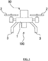
- FIG. 1 is a diagram showing an example of a flying object to which a parachute or paraglider deployment device 90 is applied.
- a flying object 100 includes an airframe 1, one or more propulsion mechanisms (for example, propellers) 2 that are coupled to the airframe 1 and propel the airframe 1, a plurality of legs 3 provided below the airframe 1, and the parachute or paraglider deployment device 90.
- the parachute or paraglider deployment device 90 is provided on the airframe 1.
- FIG. 2 showing an example of the parachute or paraglider deployment device 90, a deployment device that deploys a parachute will be described as an example.
- the parachute or paraglider deployment device 90 includes an actuator 88 and a parachute or paraglider 86.
- the actuator 88 includes an igniter 84 having a cup-shaped case 85 that houses an ignition charge (not shown), a piston 81 having a recess 82 and a piston head 83 formed integrally with the recess 82, and a bottomed cylindrical housing 80 that houses the piston 81 and regulates a propulsion direction of the piston 81.
- the parachute or paraglider 86 is housed in the housing 80 while being disposed on the piston head 83, and is a so-called parachute.
- the parachute or paraglider 86 can be directly pushed out and deployed by the propulsion of the piston 81.
- An opening end of the housing 80 is closed by a lid 87 in an initial state, and the lid 87 is detached from the opening end by pushing out the parachute or paraglider 86.
- the parachute or paraglider deployment device 90 includes a crash detection device 40 (not shown in FIG. 2 ) including an acceleration sensor or the like that detects an abnormality of the flying object.
- the piston 81 when an abnormality is detected by the crash detection device 40, the piston 81 is propelled by a gas pressure generated in response to an ignition operation of the igniter 84. Accordingly, the parachute or paraglider 86 can be directly pushed out and deployed by a propulsive force of the piston 81.
- the crash detection device 40 includes a sensor (detection part) 11 and a controller (computer having a CPU, a ROM, a RAM, and the like) 20, and is electrically connected to the igniter 84 of the deployment device 90.
- a sensor detection part
- a controller computer having a CPU, a ROM, a RAM, and the like
- the sensor 11 detects a flying state (including a collision, a crash, and the like) of the flying object 100.
- the sensor 11 is, for example, a sensor selected from at least one of an acceleration sensor, a gyro sensor, a barometric pressure sensor, a laser sensor, an ultrasonic sensor, and the like.
- the sensor 11 can acquire data on the flying state of the flying object 100 such as a speed, acceleration, inclination, altitude, and a position of the flying object 100.
- the controller 20 includes a sensor abnormality detection section 21, a calculation section 22, and a notification section 23 as a functional configuration.
- the sensor abnormality detection section 21, the calculation section 22, and the notification section 23 are functionally achieved by the controller 20 executing a predetermined program.
- the sensor abnormality detection section 21 detects an abnormal state of the sensor 11. That is, the sensor abnormality detection section 21 detects whether the sensor 11 can operate normally.
- the calculation section 22 determines whether the flying state of the flying object is abnormal, and specifically, whether the flying object 100 has been impacted (or whether the flying object 100 has collided), based on the data actually measured and acquired by the sensor 11.
- the data collection interval (sampling frequency) of the calculation section 22 can be set to, for example, any value of 1 kHz or more (preferably any value of 1 kHz to 10 kHz inclusive), and is set to 10 kHz in this embodiment.
- the calculation section 22 determines that the flying state of the flying object is abnormal, the calculation section 22 outputs an abnormal signal (which may include a command signal for activating or operating another device) to the outside.
- An abnormal signal output section may be provided separately from the calculation section 22, and the abnormal signal output section may output the abnormal signal in response to the command from the calculation section 22.
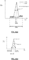
- the data detected upon detection of the impact is defined as a signal
- the unnecessary data generated as electrical noise or mechanical noise is defined as noise.
- FIG. 4(a) shows an example of the signal and the noise.
- the signal has a half width wider than the noise.
- the calculation section 22 can calculate the half width or a peak area of the signal and noise peaks shown in FIG. 4 by setting the sampling frequency to 10 kHz and taking in the data. Then, the calculation section 22 can determine whether the data is the signal or the noise based on information on the half width or the peak area of the signal and noise peaks (signal or noise determination).
- the peak area is an area of a part surrounded by a straight line (base line) parallel to a time axis connecting a start point (base start) and an end point (base end) and a target data waveform (having a peak start, a peak top, and a peak end), as indicated by the shaded area shown in FIG. 4(b) .
- the calculation section 22 determines that the flying object 100 has been impacted and outputs a deployment device activation signal to the parachute or paraglider deployment device 90.
- the notification section 23 notifies an administrator or the like that the abnormality has been detected.
- Step S1 an abnormality inspection of the sensor 11 is performed by the sensor abnormality detection section 21 (Step S1). Specifically, the sensor abnormality detection section 21 inspects whether an acceleration sensor or the like that measures the acceleration of the flying object operates normally.
- step S1 When it is not determined that there is no abnormality as a result of step S1 (NO in step S2), the sensor abnormality detection section 21 notifies the administrator or the like of an error (step S3) and ends. On the other hand, when it is determined that there is no abnormality as a result of step S1 (YES in step S2), the calculation section 22 reads the data actually measured by the sensor 11 (step S4).
- step S4 the calculation section 22 determines whether the data actually measured and acquired by the sensor 11 is a signal or noise (step S5). When the acquired data is not a signal (NO in step S6), the calculation section 22 returns to the processing in step S4.
- the calculation section 22 when the acquired data is a signal (YES in step S6), the calculation section 22 outputs a deployment device activation signal (abnormal signal) to the parachute or paraglider deployment device 90 (step S7).
- a deployment device activation signal abnormal signal
- the calculation section 22 may output the deployment device activation signal to the parachute or paraglider deployment device 90.
- the parachute or paraglider deployment device 90 that has received the deployment device activation signal is activated, deploys the parachute or paraglider (step S8), and ends.
- the deployment device 90 it is possible to guarantee the operation of the deployment device 90 and prevent a malfunction of the deployment device 90 even when noise is mixed in the actually measured data since the crash detection device 40 that can easily distinguish between the signal and the noise with the sampling frequency larger than that of the known arts is provided. This can improve the reliability of the parachute or paraglider deployment device 90 in terms of safety. Further, with no worries about noise, there is no need to attach an electromagnetic wave shielding member or perform an electromagnetic wave shielding treatment or the like on an existing member as in the known arts, thereby reducing the weight and the cost.
- the calculation section 22 calculates and the half width or the peak area of the signal and noise peaks and uses the calculated half width or peak area.
- the data actually measured and acquired by the sensor 11 can be subjected to the signal or nose determination more accurately than in the known arts.
- the sensor abnormality detection section 21 since an operation state of the sensor 11 is detected by the sensor abnormality detection section 21, it can be determined whether the sensor 11 can operate normally. The operation of the sensor 11 is thus guaranteed. This can prevent the deployment device 90 from being activated without confirming whether the sensor 11 is operable. Further, the calculation section 22 can improve the reliability of the deployment device 90 in terms of safety.
- the notification section 23 when an abnormality of the sensor 11 is detected by the sensor abnormality detection section 21, the notification section 23 notifies the administrator or the like of the detection of the abnormality. This allows the administrator or the like to easily and quickly recognize the abnormality.
- flying objects 200 and 300 including the airbag device to which the crash detection device of the above embodiment is applied will be described.
- FIG. 6 which will be described later, parts denoted by the reference signs having the same last two digits as those in FIG. 1 are similar to those described with reference to FIG. 1 unless otherwise indicated, and a description thereof will be omitted.
- FIG. 7 which will be described later, parts denoted by the reference signs having the same last two digits as those in FIGS. 1 and 6 are similar to parts described in FIG. 1 and FIG 6 unless otherwise indicated, and a description thereof will be omitted.
- the airbag is inflated by a gas pressure generated by a gas generator including the igniter.
- the gas generator may be of any type as long as it can supply gas into the airbag, and may be, for example, a cylinder type.
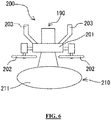
- the flying object 200 includes an airbag device 210 that inflates an airbag 211 by the gas pressure generated in response to an ignition operation of an igniter similar to the igniter 84 described above.
- the airbag device 210 is provided on an airframe 201 opposite from a parachute or paraglider deployment device 190 provided below the airframe 201 in a normal posture.
- the crash detection device when the data actually measured and acquired by the sensor (not shown) is determined to be a signal by the crash detection device (not shown) mounted on the airbag device 210, as in the case of the crash detection device 40 described above, the crash detection device transmits the deployment device activation signal to the igniter to operate the igniter. Note that, when the crash detection device mounted on the airbag device 210 determines that the data actually measured and acquired by the sensor (not shown) is noise, the crash detection device does not transmit the deployment device activation signal to the igniter.
- An airbag 311 is inflated by the gas pressure generated by the operation of the igniter. This can protect obstacles, loads, and especially pedestrians, at the time of a fall.
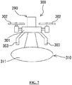
- an airbag device 310 may be provided on an airframe 301 opposite from a parachute or paraglider deployment device 290 provided above the airframe 301 in the normal posture.
- the flying object 300 is provided with a device (not shown) below the airframe 301 in the normal posture.
- the crash detection device when the data actually measured and acquired by the sensor (not shown) is determined to be a signal by the crash detection device (not shown) mounted on the airbag device 310, as in the case of the crash detection device 40 described above, the crash detection device transmits the deployment device activation signal to the igniter to operate the igniter. Note that, when the crash detection device mounted on the airbag device 310 determines that the data actually measured and acquired by the sensor (not shown) is noise, the crash detection device does not transmit the deployment device activation signal to the igniter.
- the airbag 311 when the airbag 311 is inflated by the airbag device 310 when the flying object 300 falls, pedestrians, obstacles, and especially the device of the flying object 300 can be protected.
- the airbag devices 210 and 310 include the crash detection device (not shown), a malfunction of the airbag devices 210 and 310 can be prevented. This can improve the reliability of the airbag devices 210 and 310 in terms of safety. Other advantages are similar to those in the case of the parachute or paraglider deployment device 90 described above.
- the sensor abnormality detection section 21, the calculation section 22, and the notification section 23 are functionally achieved by software.
- the present invention is not limited thereto, but may be configured by hardware.
- the sampling frequency of the calculation section 22 is set to a single value of 10 kHz for reading the data actually measured and acquired by the sensor.
- the calculation section may be configured to properly use the normal mode (sampling frequency is set to any value of less than 1 kHz (preferably 100 Hz or less)) and the abnormal mode (sampling frequency is set to any value of 1 kHz or more (preferably from 1 kHz to 10 kHz inclusive)).
- the normal mode is set to any value of less than 1 kHz (preferably 100 Hz or less)
- the abnormal mode is set to any value of 1 kHz or more (preferably from 1 kHz to 10 kHz inclusive)
- the calculation section in the crash detection device of this modification uses the normal mode at a normal time, and switches from the normal mode to the abnormal mode when the sensor detects that a certain impact or the like has been received, and then performs a signal or noise determination similar to the determination in the above embodiment.
- the abnormality inspection of the sensor is performed by the sensor abnormality detection section (Step S11). Specifically, the sensor abnormality detection section inspects whether an acceleration sensor or the like that measures the acceleration of the flying object operates normally.
- step S11 When it is not determined that there is no abnormality as a result of step S11 (NO in step S12), the sensor abnormality detection section notifies the administrator or the like of an error (step S13) and ends.
- step S13 On the other hand, when it is determined that there is no abnormality as a result of step S11 (YES in step S12), the calculation section reads the data actually measured by the sensor (step S14) in the normal mode (here, for example, the sampling frequency is set to 100 Hz).
- step S14 it is determined whether a value of the actually measured data (peak height (peak top)) is equal to or greater than a predetermined threshold value (step S15).
- a value of the actually measured data peak height (peak top)
- the calculation section 22 returns to the processing in step S14.
- the calculation section switches from the normal mode to the abnormal mode (here, for example, the sampling frequency is set to 1 kHz), and then, reads the data actually measured by the sensor (step S16).
- step S16 the calculation section determines whether the data actually measured and acquired by the sensor is a signal or noise (step S17). When the acquired data is not a signal (NO in step S18), the calculation section returns to the processing in step S14.
- the calculation section when the acquired data is a signal (YES in step S18), the calculation section outputs the deployment device activation signal (abnormal signal) to the parachute or paraglider deployment device (step S19).
- the calculation section 22 may output the deployment device activation signal to the parachute or paraglider deployment device 90.
- the parachute or paraglider deployment device that has received the deployment device activation signal is activated, deploys the parachute or paraglider (step S20), and ends.
Abstract
Description
- The present invention relates to a crash detection device mounted on a flying object, a method of detecting a crash of a flying object, a parachute or paraglider deployment device, and an airbag device.
- In recent years, with the development of an autonomous control technology and a flight control technology, an industrial use of a flying object provided with a plurality of rotor blades called a drone, for example, is accelerating. The drone flies, for example, by simultaneously rotating a plurality of rotor blades in a well-balanced manner, ascends and descends by increasing or decreasing a rotation speed of the rotor blades, and can advance and retreat by tilting an airframe by increasing or decreasing the rotation speed of the rotor blades. Such flying objects are expected to spread worldwide in the future.
- Meanwhile, the risk of fall accidents of the flying objects as described above is considered to be dangerous and hinders spread of the flying objects. In order to reduce the risk of such fall accidents, parachute deployment devices, airbag devices, and the like have been commercialized as safety devices. For example,
Patent Literature 1 discloses an autonomous parachute-opening device for a flying object that detects that the flying object is at a predetermined altitude or higher, and then compares a flying posture parameter and a battery capacity parameter with predetermined values, and when an abnormality is detected, stops power supply to the flying object and automatically opens a parachute. - Patent Literature 1:
CN 105775142 A - However, in the known arts including the above Patent Literature, there is room for further improving the speed and reliability of the abnormality detection of flying objects. Specifically, the known arts do not consider the speed and reliability of data collection for detecting an abnormality of the flying object, and cannot prevent a malfunction in an effort to improve the accuracy of detecting an abnormality of the flying object.
- It is therefore an object of the present invention to provide a crash detection device, a method of detecting a crash of a flying object, a parachute or paraglider deployment device, and an airbag device that can improve the reliability of the flying object in terms of safety.
-
- (1) The present invention is a crash detection device that can be mounted on a flying object and that can detect a crash of the flying object, the crash detection device including a detection part that can detect a flying state of the flying object, a calculation section that can determine whether the flying state of the flying object is abnormal based on data on the flying state of the flying object acquired by the detection part, and an abnormal signal output section capable of outputting an abnormal signal to the outside when the calculation section determines that the flying state of the flying object is abnormal, in which the calculation section acquires the data from the detection part at a sampling frequency of 1 kHz or more, determines whether the data is data indicating that the flying state of the flying object is abnormal or noise that is unnecessary data (hereinafter, a signal or noise determination), and determines that the flying state of the flying object is abnormal when the data is determined to be the data indicating that the flying state of the flying object is abnormal. Note that the calculation section may output the abnormal signal to the outside when determining that the flying state of the flying object is abnormal.
According to the configuration of the above (1), since the sampling frequency is larger than that of the known arts, the data indicating that the flying state of the flying object is abnormal (signal) and the noise that is unnecessary data can be easily distinguished even when noise is mixed in the data actually measured by the detection part. It is therefore possible to accurately detect whether the flying state of the flying object is abnormal. Further, with no worries about noise such as electrical noise or mechanical noise, there is no need to attach an electromagnetic wave shielding member to the crash detection device or perform an electromagnetic wave shielding treatment or the like on an existing member as in the known arts, thereby reducing the weight and the cost. - (2) In the crash detection device of the above (1), preferably, the calculation section includes an abnormal mode in which the data is acquired from the detection part at the sampling frequency of 1 kHz or more, and a normal mode in which the data is acquired from the detection part at a sampling frequency of less than 1 kHz at a normal time when there is no abnormality, and the calculation section is in the normal mode in an initial state, and the calculation section switches from the normal mode to the abnormal mode and acquires the data from the detection part when the data acquired from the detection part is equal to or greater than a predetermined threshold value in the normal mode.
According to the configuration of the above (2), with a configuration that the normal mode is used at the normal time and the abnormal mode is used at a time of emergency, a useless data collection can be suppressed as compared with the case of the configuration of the above (1) (only data to be examined can be picked up and collected). Thus, power consumption can be saved as compared with the configuration of the above (1). - (3) In the crash detection device according to (1) or (2), the calculation section preferably performs the signal or noise determination based on information on a half width or a peak area of a peak of the data acquired by calculating the data acquired from the detection part.
According to the configuration of the above (3), the calculation section calculates the half width or the peak area of the signal and noise peaks and uses the calculated half width or peak area. Thus, the data actually measured and acquired by the detection part can be subjected to the signal or noise determination more accurately than in the known arts. - (4) As another aspect, the present invention is a method of detecting a crash of a flying object including a safety device, the method may include a data acquisition step of acquiring a data of a flying state of the flying object at a sampling frequency of 1 kHz or more, a first determination step of determining whether the data acquired in the data acquisition step is equal to or greater than a predetermined threshold value, a second determination step of determining whether the data is data indicating that a flying state of the flying object is abnormal or noise that is unnecessary data when the data is determined to be equal to or greater than the predetermined threshold value by the first determination step, and a step of activating the safety device by the second determination step when the data is determined to be the data indicating that the flying state of the flying object is abnormal.
According to the configuration of the above (4), effects similar to the above (1) can be acquired. - (5) As another aspect, the parachute or paraglider deployment device of the present invention includes the crash detection device according to any one of the above (1) to (3), a parachute or a paraglider that is deployable, and an ejection device that, when an abnormal signal is output by the crash detection device, receives the abnormal signal and ejects the parachute or the paraglider.
According to the configuration of the above (5), even when noise is mixed in the actually measured data, it is possible to guarantee the operation of the parachute or paraglider deployment device and prevent a malfunction of the deployment device since the crash detection device that can easily distinguish between the signal and the noise is provided. This can improve the reliability of the parachute or paraglider deployment device in terms of safety. - (6) As still another aspect, the airbag device of the present invention includes an airbag that is inflatable, a crash detection device according to any one of (1) to (3), and a gas generator that, when an abnormal signal is output by the crash detection device, receives the abnormal signal and supplies gas into the airbag.
According to the configuration of the above (6), even when noise is mixed in the actually measured data, it is possible to guarantee the operation of the airbag device and prevent a malfunction of the airbag device since the crash detection device that can easily distinguish between the signal and the noise is provided. This can improve the reliability of the airbag device in terms of safety. - According to the present invention, it is possible to provide a crash detection device, a method of detecting a crash of a flying object, a parachute or paraglider deployment device, and an airbag device that can improve the reliability of the flying object in terms of safety.
-
-
FIG. 1 is a view showing an example of a flying object to which a parachute or paraglider deployment device according to one embodiment of the present invention is applied. -
FIG. 2 is a cross-sectional view showing a parachute or paraglider deployment device according to one embodiment of the present invention. -
FIG. 3 is a block diagram showing a functional configuration of a crash detection device provided in the deployment device ofFIG. 2 . -
FIG. 4(a) is a graph showing an example of a signal and noise, andFIG. 4(b) is a graph for explaining a peak area. -
FIG. 5 is a flowchart showing an example of an operation of the crash detection device. -
FIG. 6 is a diagram showing an example of a flying object provided with an airbag device to which the crash detection device is applied. -
FIG. 7 is a diagram showing another example of a flying object provided with an airbag device to which the crash detection device is applied. -
FIG. 8 is a flowchart showing another example of the operation of the crash detection device. - Hereinafter, a flying object to which a parachute or paraglider deployment device according to one embodiment of the present invention is applied will be described with reference to the drawings.
-
FIG. 1 is a diagram showing an example of a flying object to which a parachute orparaglider deployment device 90 is applied. As shown inFIG. 1 , aflying object 100 includes anairframe 1, one or more propulsion mechanisms (for example, propellers) 2 that are coupled to theairframe 1 and propel theairframe 1, a plurality oflegs 3 provided below theairframe 1, and the parachute orparaglider deployment device 90. The parachute orparaglider deployment device 90 is provided on theairframe 1. - In
FIG. 2 showing an example of the parachute orparaglider deployment device 90, a deployment device that deploys a parachute will be described as an example. - As shown in
FIG. 2 , the parachute orparaglider deployment device 90 includes anactuator 88 and a parachute orparaglider 86. Theactuator 88 includes anigniter 84 having a cup-shaped case 85 that houses an ignition charge (not shown), apiston 81 having arecess 82 and apiston head 83 formed integrally with therecess 82, and a bottomedcylindrical housing 80 that houses thepiston 81 and regulates a propulsion direction of thepiston 81. The parachute orparaglider 86 is housed in thehousing 80 while being disposed on thepiston head 83, and is a so-called parachute. In such a configuration, the parachute orparaglider 86 can be directly pushed out and deployed by the propulsion of thepiston 81. An opening end of thehousing 80 is closed by alid 87 in an initial state, and thelid 87 is detached from the opening end by pushing out the parachute orparaglider 86. - Further, the parachute or
paraglider deployment device 90 includes a crash detection device 40 (not shown inFIG. 2 ) including an acceleration sensor or the like that detects an abnormality of the flying object. - In such a configuration, when an abnormality is detected by the
crash detection device 40, thepiston 81 is propelled by a gas pressure generated in response to an ignition operation of theigniter 84. Accordingly, the parachute orparaglider 86 can be directly pushed out and deployed by a propulsive force of thepiston 81. - Here, a functional configuration of the
crash detection device 40 will be described. As shown inFIG. 3 , thecrash detection device 40 includes a sensor (detection part) 11 and a controller (computer having a CPU, a ROM, a RAM, and the like) 20, and is electrically connected to theigniter 84 of thedeployment device 90. - The
sensor 11 detects a flying state (including a collision, a crash, and the like) of theflying object 100. Specifically, thesensor 11 is, for example, a sensor selected from at least one of an acceleration sensor, a gyro sensor, a barometric pressure sensor, a laser sensor, an ultrasonic sensor, and the like. Thesensor 11 can acquire data on the flying state of theflying object 100 such as a speed, acceleration, inclination, altitude, and a position of theflying object 100. - The
controller 20 includes a sensorabnormality detection section 21, acalculation section 22, and anotification section 23 as a functional configuration. The sensorabnormality detection section 21, thecalculation section 22, and thenotification section 23 are functionally achieved by thecontroller 20 executing a predetermined program. - The sensor
abnormality detection section 21 detects an abnormal state of thesensor 11. That is, the sensorabnormality detection section 21 detects whether thesensor 11 can operate normally. - The
calculation section 22 determines whether the flying state of the flying object is abnormal, and specifically, whether the flyingobject 100 has been impacted (or whether the flyingobject 100 has collided), based on the data actually measured and acquired by thesensor 11. The data collection interval (sampling frequency) of thecalculation section 22 can be set to, for example, any value of 1 kHz or more (preferably any value of 1 kHz to 10 kHz inclusive), and is set to 10 kHz in this embodiment. When thecalculation section 22 determines that the flying state of the flying object is abnormal, thecalculation section 22 outputs an abnormal signal (which may include a command signal for activating or operating another device) to the outside. An abnormal signal output section may be provided separately from thecalculation section 22, and the abnormal signal output section may output the abnormal signal in response to the command from thecalculation section 22. - Here, the data detected upon detection of the impact is defined as a signal, and the unnecessary data generated as electrical noise or mechanical noise is defined as noise.
FIG. 4(a) shows an example of the signal and the noise. The signal has a half width wider than the noise. Using these characteristics, thecalculation section 22 can calculate the half width or a peak area of the signal and noise peaks shown inFIG. 4 by setting the sampling frequency to 10 kHz and taking in the data. Then, thecalculation section 22 can determine whether the data is the signal or the noise based on information on the half width or the peak area of the signal and noise peaks (signal or noise determination). The peak area is an area of a part surrounded by a straight line (base line) parallel to a time axis connecting a start point (base start) and an end point (base end) and a target data waveform (having a peak start, a peak top, and a peak end), as indicated by the shaded area shown inFIG. 4(b) . Further, when determining that the data is the signal, thecalculation section 22 determines that the flyingobject 100 has been impacted and outputs a deployment device activation signal to the parachute orparaglider deployment device 90. - When the sensor
abnormality detection section 21 detects the abnormality of thesensor 11, thenotification section 23 notifies an administrator or the like that the abnormality has been detected. - Subsequently, a flow of an operation of the
crash detection device 40 of this embodiment will be described using a flowchart. - As shown in
FIG. 5 , first, an abnormality inspection of thesensor 11 is performed by the sensor abnormality detection section 21 (Step S1). Specifically, the sensorabnormality detection section 21 inspects whether an acceleration sensor or the like that measures the acceleration of the flying object operates normally. - When it is not determined that there is no abnormality as a result of step S1 (NO in step S2), the sensor
abnormality detection section 21 notifies the administrator or the like of an error (step S3) and ends. On the other hand, when it is determined that there is no abnormality as a result of step S1 (YES in step S2), thecalculation section 22 reads the data actually measured by the sensor 11 (step S4). - After step S4, the
calculation section 22 determines whether the data actually measured and acquired by thesensor 11 is a signal or noise (step S5). When the acquired data is not a signal (NO in step S6), thecalculation section 22 returns to the processing in step S4. - On the other hand, when the acquired data is a signal (YES in step S6), the
calculation section 22 outputs a deployment device activation signal (abnormal signal) to the parachute or paraglider deployment device 90 (step S7). Note that, as one modification, when the acquired data is a signal, and furthermore, when a peak height (peak top) of the signal is equal to or greater than a predetermined threshold value, thecalculation section 22 may output the deployment device activation signal to the parachute orparaglider deployment device 90. - Then, the parachute or
paraglider deployment device 90 that has received the deployment device activation signal is activated, deploys the parachute or paraglider (step S8), and ends. - As described above, according to this embodiment, it is possible to guarantee the operation of the
deployment device 90 and prevent a malfunction of thedeployment device 90 even when noise is mixed in the actually measured data since thecrash detection device 40 that can easily distinguish between the signal and the noise with the sampling frequency larger than that of the known arts is provided. This can improve the reliability of the parachute orparaglider deployment device 90 in terms of safety. Further, with no worries about noise, there is no need to attach an electromagnetic wave shielding member or perform an electromagnetic wave shielding treatment or the like on an existing member as in the known arts, thereby reducing the weight and the cost. - Further, according to this embodiment, the
calculation section 22 calculates and the half width or the peak area of the signal and noise peaks and uses the calculated half width or peak area. Thus, the data actually measured and acquired by thesensor 11 can be subjected to the signal or nose determination more accurately than in the known arts. - Further, according to this embodiment, since an operation state of the
sensor 11 is detected by the sensorabnormality detection section 21, it can be determined whether thesensor 11 can operate normally. The operation of thesensor 11 is thus guaranteed. This can prevent thedeployment device 90 from being activated without confirming whether thesensor 11 is operable. Further, thecalculation section 22 can improve the reliability of thedeployment device 90 in terms of safety. - Further, according to this embodiment, when an abnormality of the
sensor 11 is detected by the sensorabnormality detection section 21, thenotification section 23 notifies the administrator or the like of the detection of the abnormality. This allows the administrator or the like to easily and quickly recognize the abnormality. - Next, flying
objects FIG. 6 , which will be described later, parts denoted by the reference signs having the same last two digits as those inFIG. 1 are similar to those described with reference toFIG. 1 unless otherwise indicated, and a description thereof will be omitted. Similarly, inFIG. 7 , which will be described later, parts denoted by the reference signs having the same last two digits as those inFIGS. 1 and6 are similar to parts described inFIG. 1 andFIG 6 unless otherwise indicated, and a description thereof will be omitted. In the airbag device used herein, the airbag is inflated by a gas pressure generated by a gas generator including the igniter. Note that the gas generator may be of any type as long as it can supply gas into the airbag, and may be, for example, a cylinder type. - As shown in
FIG. 6 , the flyingobject 200 includes anairbag device 210 that inflates anairbag 211 by the gas pressure generated in response to an ignition operation of an igniter similar to theigniter 84 described above. Theairbag device 210 is provided on anairframe 201 opposite from a parachute orparaglider deployment device 190 provided below theairframe 201 in a normal posture. - In such a configuration, when the data actually measured and acquired by the sensor (not shown) is determined to be a signal by the crash detection device (not shown) mounted on the
airbag device 210, as in the case of thecrash detection device 40 described above, the crash detection device transmits the deployment device activation signal to the igniter to operate the igniter. Note that, when the crash detection device mounted on theairbag device 210 determines that the data actually measured and acquired by the sensor (not shown) is noise, the crash detection device does not transmit the deployment device activation signal to the igniter. - An
airbag 311 is inflated by the gas pressure generated by the operation of the igniter. This can protect obstacles, loads, and especially pedestrians, at the time of a fall. - Further, as shown in
FIG. 7 , in the flyingobject 300, anairbag device 310 may be provided on anairframe 301 opposite from a parachute orparaglider deployment device 290 provided above theairframe 301 in the normal posture. The flyingobject 300 is provided with a device (not shown) below theairframe 301 in the normal posture. - In such a configuration, when the data actually measured and acquired by the sensor (not shown) is determined to be a signal by the crash detection device (not shown) mounted on the
airbag device 310, as in the case of thecrash detection device 40 described above, the crash detection device transmits the deployment device activation signal to the igniter to operate the igniter. Note that, when the crash detection device mounted on theairbag device 310 determines that the data actually measured and acquired by the sensor (not shown) is noise, the crash detection device does not transmit the deployment device activation signal to the igniter. - Further, when the
airbag 311 is inflated by theairbag device 310 when the flyingobject 300 falls, pedestrians, obstacles, and especially the device of the flyingobject 300 can be protected. - As described above, since the
airbag devices airbag devices airbag devices paraglider deployment device 90 described above. - As described above, the embodiment of the present invention has been described with reference to the drawings. However, the specific configuration of the present invention shall not be interpreted as to be limited to the above described embodiment. The scope of the present invention is defined not by the above embodiment but by claims set forth below, and shall encompass the equivalents in the meaning of the claims and every modification within the scope of the claims.
- In the above-described embodiment, the sensor
abnormality detection section 21, thecalculation section 22, and thenotification section 23 are functionally achieved by software. However, the present invention is not limited thereto, but may be configured by hardware. - In the above-described embodiment, the sampling frequency of the
calculation section 22 is set to a single value of 10 kHz for reading the data actually measured and acquired by the sensor. Alternatively, the calculation section may be configured to properly use the normal mode (sampling frequency is set to any value of less than 1 kHz (preferably 100 Hz or less)) and the abnormal mode (sampling frequency is set to any value of 1 kHz or more (preferably from 1 kHz to 10 kHz inclusive)). Hereinafter, a specific example of this configuration will be described. Note that parts using the part names similar to those in the above-described embodiment are similar unless otherwise specified, and thus a description may be omitted. Further, components that are not particularly described are similar to those in the above-described embodiment, and thus a description thereof may be omitted. - The calculation section in the crash detection device of this modification uses the normal mode at a normal time, and switches from the normal mode to the abnormal mode when the sensor detects that a certain impact or the like has been received, and then performs a signal or noise determination similar to the determination in the above embodiment.
- Subsequently, a flow of the operation of the crash detection device of this modification will be described using a flowchart. Note that the calculation section in the crash detection device of this modification is in the normal mode in the initial state.
- As shown in
FIG. 8 , first, the abnormality inspection of the sensor is performed by the sensor abnormality detection section (Step S11). Specifically, the sensor abnormality detection section inspects whether an acceleration sensor or the like that measures the acceleration of the flying object operates normally. - When it is not determined that there is no abnormality as a result of step S11 (NO in step S12), the sensor abnormality detection section notifies the administrator or the like of an error (step S13) and ends. On the other hand, when it is determined that there is no abnormality as a result of step S11 (YES in step S12), the calculation section reads the data actually measured by the sensor (step S14) in the normal mode (here, for example, the sampling frequency is set to 100 Hz).
- After step S14, it is determined whether a value of the actually measured data (peak height (peak top)) is equal to or greater than a predetermined threshold value (step S15). When the value of the acquired data is not equal to or greater than the predetermined threshold value (NO in step S15), the
calculation section 22 returns to the processing in step S14. - On the other hand, when the value of the acquired data is equal to or greater than the predetermined threshold value (YES in step S15), the calculation section switches from the normal mode to the abnormal mode (here, for example, the sampling frequency is set to 1 kHz), and then, reads the data actually measured by the sensor (step S16).
- After step S16, the calculation section determines whether the data actually measured and acquired by the sensor is a signal or noise (step S17). When the acquired data is not a signal (NO in step S18), the calculation section returns to the processing in step S14.
- On the other hand, when the acquired data is a signal (YES in step S18), the calculation section outputs the deployment device activation signal (abnormal signal) to the parachute or paraglider deployment device (step S19). Note that, as a modification, when the acquired data is a signal, and furthermore, when the peak height (peak top) of the signal is equal to or greater than another predetermined threshold value, the
calculation section 22 may output the deployment device activation signal to the parachute orparaglider deployment device 90. - Then, the parachute or paraglider deployment device that has received the deployment device activation signal is activated, deploys the parachute or paraglider (step S20), and ends.
- Accordingly, the operational advantages similar to those of the parachute or
paraglider deployment device 90 of the above embodiment can be acquired. Further, in the calculation section of this modification, with a configuration that the normal mode is used at the normal time and the abnormal mode is used at a time of emergency, a useless data collection can be suppressed as compared with the case of the above embodiment (only data highly required to be examined can be picked up and collected). Thus, power consumption can be saved as compared with the above embodiment. -
- 1, 201, 301
- Airframe
- 2, 202, 302
- Propulsion mechanism
- 3, 203, 303
- Leg
- 20
- Controller
- 21
- Sensor abnormality detection section
- 22
- Calculation section
- 23
- Notification section
- 80
- Housing
- 81
- Piston
- 82
- Recess
- 83
- Piston head
- 84
- Igniter
- 85
- Case
- 86
- Parachute or paraglider
- 87
- Lid
- 88
- Actuator
- 90, 190, 290
- Parachute or paraglider deployment device
- 100, 200, 300
- Flying object
- 210,310
- Airbag device
- 211, 311
- Airbag
Claims (6)
- A crash detection device that can be mounted on a flying object and that can detect a crash of the flying object, the crash detection device comprising:a detection part that can detect a flying state of the flying object; anda calculation section that can determine whether the flying state of the flying object is abnormal based on data on the flying state of the flying object acquired by the detection part,wherein the calculation section acquires the data from the detection part at a sampling frequency of 1 kHz or more, determines whether the data is data indicating that the flying state of the flying object is abnormal or noise that is unnecessary data (hereinafter, a signal or noise determination), and determines that the flying state of the flying object is abnormal when the data is determined to be the data indicating that the flying state of the flying object is abnormal.
- The crash detection device according to claim 1,
wherein the calculation section includes an abnormal mode in which the data is acquired from the detection part at the sampling frequency of 1 kHz or more, and a normal mode in which the data is acquired from the detection part at a sampling frequency of less than 1 kHz at a normal time when there is no abnormality, and
the calculation section is in the normal mode in an initial state, and the calculation section switches from the normal mode to the abnormal mode and acquires the data from the detection part when the data acquired from the detection part is equal to or greater than a predetermined threshold value in the normal mode. - The crash detection device according to claim 1 or 2, wherein the calculation section performs the signal or noise determination based on information on a half width or a peak area of a peak of the data acquired by calculating the data acquired from the detection part.
- A method of detecting a crash of a flying object, the flying object including a safety device, the method comprising:a data acquisition step of acquiring a data of a flying state of the flying object at a sampling frequency of 1 kHz or more;a first determination step of determining whether the data acquired in the data acquisition step is equal to or greater than a predetermined threshold value;a second determination step of determining whether the data is data indicating that a flying state of the flying object is abnormal or noise that is unnecessary data when the data is determined to be equal to or greater than the predetermined threshold value by the first determination step; anda step of activating the safety device by the second determination step when the data is determined to be the data indicating that the flying state of the flying object is abnormal.
- A parachute or paraglider deployment device comprising:a crash detection device described in any one of claims 1 to 3;a parachute or a paraglider that is deployable; andan ejection device that, when an abnormal signal is output by the crash detection device, receives the abnormal signal and ejects the parachute or the paraglider.
- An airbag device comprising:an airbag that is inflatable;a crash detection device described in any one of claims 1 to 3; anda gas generator that, when an abnormal signal is output by the crash detection device, receives the abnormal signal and supplies gas into the airbag.
Applications Claiming Priority (2)
| Application Number | Priority Date | Filing Date | Title |
|---|---|---|---|
| JP2017200320A JP6905445B2 (en) | 2017-10-16 | 2017-10-16 | Crash detectors, methods for detecting aircraft crashes, parachute or paraglider deployment devices, and airbag devices |
| PCT/JP2018/038008 WO2019078094A1 (en) | 2017-10-16 | 2018-10-11 | Crash detection device, flying body crash detection method, parachute or paraglider deployment device, and airbag device |
Publications (3)
| Publication Number | Publication Date |
|---|---|
| EP3699089A1 true EP3699089A1 (en) | 2020-08-26 |
| EP3699089A4 EP3699089A4 (en) | 2021-07-14 |
| EP3699089B1 EP3699089B1 (en) | 2023-02-15 |
Family
ID=66173707
Family Applications (1)
| Application Number | Title | Priority Date | Filing Date |
|---|---|---|---|
| EP18867458.4A Active EP3699089B1 (en) | 2017-10-16 | 2018-10-11 | Crash detection device, flying body crash detection method, parachute or paraglider deployment device, and airbag device |
Country Status (5)
| Country | Link |
|---|---|
| US (1) | US20200239136A1 (en) |
| EP (1) | EP3699089B1 (en) |
| JP (2) | JP6905445B2 (en) |
| CN (1) | CN111164014B (en) |
| WO (1) | WO2019078094A1 (en) |
Cited By (1)
| Publication number | Priority date | Publication date | Assignee | Title |
|---|---|---|---|---|
| CN112526916A (en) * | 2020-10-27 | 2021-03-19 | 成都飞机工业(集团)有限责任公司 | Airplane assembly fixture collision monitoring method |
Families Citing this family (4)
| Publication number | Priority date | Publication date | Assignee | Title |
|---|---|---|---|---|
| JP6217054B1 (en) * | 2016-11-04 | 2017-10-25 | 株式会社松屋アールアンドディ | Drone with airbag |
| US20230012473A1 (en) * | 2016-12-20 | 2023-01-19 | Nippon Kayaku Kabushiki Kaisha | Airbag device for aircraft |
| JP6385604B1 (en) * | 2018-01-22 | 2018-09-05 | 株式会社松屋アールアンドディ | Control method of drone with airbag and drone with airbag |
| JP6857753B1 (en) * | 2020-01-15 | 2021-04-14 | 日本化薬株式会社 | Circuit abnormality diagnostic device, current generator, deployable body injection device for flying object, airbag device for flying object, and cutting device for flying object |
Family Cites Families (31)
| Publication number | Priority date | Publication date | Assignee | Title |
|---|---|---|---|---|
| JP3550353B2 (en) * | 2000-11-16 | 2004-08-04 | 本田技研工業株式会社 | Vibration and noise control device for vehicles |
| US6685140B2 (en) * | 2001-09-27 | 2004-02-03 | Ernest A. Carroll | Miniature, unmanned aircraft with automatically deployed parachute |
| US7640139B2 (en) * | 2004-10-18 | 2009-12-29 | Nsk Ltd. | Abnormality diagnosing system for mechanical equipment |
| JP2006113002A (en) * | 2004-10-18 | 2006-04-27 | Nsk Ltd | Anomaly diagnosis system for mechanical equipment |
| EP2203910B1 (en) * | 2007-09-19 | 2013-01-23 | Koninklijke Philips Electronics N.V. | Method and apparatus for detecting an abnormal situation |
| JP5363213B2 (en) * | 2009-06-30 | 2013-12-11 | 東京エレクトロン株式会社 | Abnormality detection system, abnormality detection method, storage medium, and substrate processing apparatus |
| JP5482119B2 (en) * | 2009-11-10 | 2014-04-23 | 株式会社Ihi | Fatigue damage evaluation method and apparatus |
| JP2012177568A (en) * | 2011-02-25 | 2012-09-13 | Arkray Inc | Data processing device, data processing method, and data processing program |
| CN102521088A (en) * | 2011-11-15 | 2012-06-27 | 浪潮电子信息产业股份有限公司 | Acoustic detection based status detection method of server fan |
| JP5802184B2 (en) * | 2012-11-07 | 2015-10-28 | 旭化成エレクトロニクス株式会社 | Noise removal device for inertial sensor and noise removal method thereof |
| CN104058095B (en) * | 2014-06-12 | 2016-06-29 | 深圳市哈博森科技有限公司 | Aircraft parachute controls system and method |
| CN107406090B (en) * | 2015-01-16 | 2020-11-20 | 国际电子机械公司 | Abnormal vehicle dynamics detection |
| US9454907B2 (en) * | 2015-02-07 | 2016-09-27 | Usman Hafeez | System and method for placement of sensors through use of unmanned aerial vehicles |
| CN105099585B (en) * | 2015-08-03 | 2017-11-24 | 陈昊 | Unmanned plane signal processing apparatus and signal processing method |
| CN204993363U (en) * | 2015-08-03 | 2016-01-20 | 陈昊 | Unmanned aerial vehicle signal processing device |
| US10112721B2 (en) * | 2015-10-14 | 2018-10-30 | Flirtey Holdings, Inc. | Parachute deployment system for an unmanned aerial vehicle |
| CN105253306A (en) * | 2015-11-09 | 2016-01-20 | 杨珊珊 | UAV (Unmanned aerial vehicle) provided with falling guard device and falling guard method thereof |
| CN105302043B (en) * | 2015-11-17 | 2019-02-22 | 重庆国飞通用航空设备制造有限公司 | A kind of method of controlling security of unmanned plane |
| JP6169671B2 (en) * | 2015-11-26 | 2017-07-26 | 株式会社オプティム | Unmanned aerial vehicle, unmanned aircraft control method, and unmanned aircraft control program |
| KR102476233B1 (en) * | 2016-03-25 | 2022-12-09 | 엘지이노텍 주식회사 | Drone |
| CN107087429B (en) * | 2016-03-25 | 2020-04-07 | 深圳前海达闼云端智能科技有限公司 | Aircraft control method and device |
| CN105775142A (en) | 2016-03-25 | 2016-07-20 | 深圳市轻准科技有限公司 | Autonomous parachute opening safety protection method and system for small aircraft |
| CN205707374U (en) * | 2016-04-20 | 2016-11-23 | 杨起 | A kind of unmanned plane air crash protection device |
| CN106409278B (en) * | 2016-09-18 | 2019-10-08 | 哈尔滨工业大学(威海) | A kind of unmanned plane active noise controller |
| CN206087255U (en) * | 2016-10-09 | 2017-04-12 | 东莞前沿技术研究院 | Emergent descending system of dirigible nacelle |
| CN106347643A (en) * | 2016-11-02 | 2017-01-25 | 王宇飞 | Automatic protection system for unmanned plane |
| CN206282146U (en) * | 2016-11-23 | 2017-06-27 | 歌尔股份有限公司 | A kind of unmanned plane and wearable device |
| CN106774381B (en) * | 2016-11-23 | 2019-07-19 | 歌尔股份有限公司 | Detection method, the wearable device of a kind of unmanned plane and its state of flight |
| US9639087B1 (en) * | 2016-12-06 | 2017-05-02 | Kitty Hawk Corporation | Emergency landing using inertial sensors |
| US11195345B2 (en) * | 2016-12-14 | 2021-12-07 | Telefonaktiebolaget Lm Ericsson (Publ) | Methods and entities for alerting about failure of an unmanned aerial vehicle |
| CN106628194B (en) * | 2017-02-20 | 2019-02-05 | 北京京东尚科信息技术有限公司 | The parachute system of unmanned plane, safeguard method and device |
-
2017
- 2017-10-16 JP JP2017200320A patent/JP6905445B2/en active Active
-
2018
- 2018-10-11 CN CN201880064342.6A patent/CN111164014B/en active Active
- 2018-10-11 EP EP18867458.4A patent/EP3699089B1/en active Active
- 2018-10-11 US US16/756,583 patent/US20200239136A1/en active Pending
- 2018-10-11 WO PCT/JP2018/038008 patent/WO2019078094A1/en unknown
-
2021
- 2021-06-22 JP JP2021103075A patent/JP7089623B2/en active Active
Cited By (1)
| Publication number | Priority date | Publication date | Assignee | Title |
|---|---|---|---|---|
| CN112526916A (en) * | 2020-10-27 | 2021-03-19 | 成都飞机工业(集团)有限责任公司 | Airplane assembly fixture collision monitoring method |
Also Published As
| Publication number | Publication date |
|---|---|
| CN111164014B (en) | 2023-10-31 |
| JP2021151874A (en) | 2021-09-30 |
| US20200239136A1 (en) | 2020-07-30 |
| EP3699089A4 (en) | 2021-07-14 |
| WO2019078094A1 (en) | 2019-04-25 |
| EP3699089B1 (en) | 2023-02-15 |
| JP6905445B2 (en) | 2021-07-21 |
| JP7089623B2 (en) | 2022-06-22 |
| CN111164014A (en) | 2020-05-15 |
| JP2019073149A (en) | 2019-05-16 |
Similar Documents
| Publication | Publication Date | Title |
|---|---|---|
| EP3699089B1 (en) | Crash detection device, flying body crash detection method, parachute or paraglider deployment device, and airbag device | |
| CN110709322B (en) | Flying body and method for controlling flying body | |
| EP3770068A1 (en) | Flying object operation device, malfunction prevention method for flying object operation device, flying object thrust generation device, parachute or paraglider deploying device, and airbag device | |
| JP7034091B2 (en) | Airbag device for flying objects | |
| EP3508426A1 (en) | Small flying body provided with airbag device | |
| WO2017086234A1 (en) | Unmanned airplane | |
| KR20170111192A (en) | Drone | |
| KR101700746B1 (en) | Fail-safe apparatus and method for flight vehicle | |
| KR20190118203A (en) | Aircraft with Second Flight Assembly | |
| JP2018203188A (en) | Crash detection device and flight vehicle including the same | |
| WO2021161685A1 (en) | Flying device and parachute device | |
| JP2017056822A (en) | Radio control multicopter | |
| JP2019043253A (en) | Flying body failure detection system, method for detecting failure in battery in which multiple cells are connected, device for deploying parachute or paraglider, and air bag device | |
| JP2017007422A (en) | Radio control multicopter | |
| EP3805099A1 (en) | Emergency landing device | |
| US8800923B2 (en) | Method of activating protection means for protecting an occupant of an aircraft, and an aircraft implementing said method | |
| EP4289727A1 (en) | Safety device and flight vehicle | |
| EP3037344B1 (en) | A propeller blade for an aircraft engine | |
| JP6800538B2 (en) | Unmanned aerial vehicle, unmanned aerial vehicle fall judgment device and fall judgment method | |
| JP2000111298A (en) | Guided missile | |
| RU2003101688A (en) | METHOD FOR INDICATING THE POSITION OF THE AIRCRAFT AFTER I FALL AS A RESULT OF AN ACCIDENT |
Legal Events
| Date | Code | Title | Description |
|---|---|---|---|
| STAA | Information on the status of an ep patent application or granted ep patent |
Free format text: STATUS: THE INTERNATIONAL PUBLICATION HAS BEEN MADE |
|
| PUAI | Public reference made under article 153(3) epc to a published international application that has entered the european phase |
Free format text: ORIGINAL CODE: 0009012 |
|
| STAA | Information on the status of an ep patent application or granted ep patent |
Free format text: STATUS: REQUEST FOR EXAMINATION WAS MADE |
|
| 17P | Request for examination filed |
Effective date: 20200511 |
|
| AK | Designated contracting states |
Kind code of ref document: A1 Designated state(s): AL AT BE BG CH CY CZ DE DK EE ES FI FR GB GR HR HU IE IS IT LI LT LU LV MC MK MT NL NO PL PT RO RS SE SI SK SM TR |
|
| AX | Request for extension of the european patent |
Extension state: BA ME |
|
| DAV | Request for validation of the european patent (deleted) | ||
| DAX | Request for extension of the european patent (deleted) | ||
| A4 | Supplementary search report drawn up and despatched |
Effective date: 20210611 |
|
| RIC1 | Information provided on ipc code assigned before grant |
Ipc: B64D 25/00 20060101AFI20210607BHEP Ipc: B64C 39/02 20060101ALI20210607BHEP Ipc: B64D 17/54 20060101ALI20210607BHEP Ipc: B64D 45/00 20060101ALN20210607BHEP |
|
| GRAP | Despatch of communication of intention to grant a patent |
Free format text: ORIGINAL CODE: EPIDOSNIGR1 |
|
| STAA | Information on the status of an ep patent application or granted ep patent |
Free format text: STATUS: GRANT OF PATENT IS INTENDED |
|
| RIC1 | Information provided on ipc code assigned before grant |
Ipc: B64D 45/00 20060101ALN20220930BHEP Ipc: B64D 17/54 20060101ALI20220930BHEP Ipc: B64C 39/02 20060101ALI20220930BHEP Ipc: B64D 25/00 20060101AFI20220930BHEP |
|
| INTG | Intention to grant announced |
Effective date: 20221019 |
|
| RIC1 | Information provided on ipc code assigned before grant |
Ipc: B64D 45/00 20060101ALN20221007BHEP Ipc: B64D 17/54 20060101ALI20221007BHEP Ipc: B64C 39/02 20060101ALI20221007BHEP Ipc: B64D 25/00 20060101AFI20221007BHEP |
|
| GRAS | Grant fee paid |
Free format text: ORIGINAL CODE: EPIDOSNIGR3 |
|
| GRAA | (expected) grant |
Free format text: ORIGINAL CODE: 0009210 |
|
| STAA | Information on the status of an ep patent application or granted ep patent |
Free format text: STATUS: THE PATENT HAS BEEN GRANTED |
|
| AK | Designated contracting states |
Kind code of ref document: B1 Designated state(s): AL AT BE BG CH CY CZ DE DK EE ES FI FR GB GR HR HU IE IS IT LI LT LU LV MC MK MT NL NO PL PT RO RS SE SI SK SM TR |
|
| REG | Reference to a national code |
Ref country code: CH Ref legal event code: EP Ref country code: GB Ref legal event code: FG4D |
|
| REG | Reference to a national code |
Ref country code: DE Ref legal event code: R096 Ref document number: 602018046255 Country of ref document: DE |
|
| REG | Reference to a national code |
Ref country code: AT Ref legal event code: REF Ref document number: 1548131 Country of ref document: AT Kind code of ref document: T Effective date: 20230315 Ref country code: IE Ref legal event code: FG4D |
|
| REG | Reference to a national code |
Ref country code: LT Ref legal event code: MG9D |
|
| REG | Reference to a national code |
Ref country code: NL Ref legal event code: MP Effective date: 20230215 |
|
| REG | Reference to a national code |
Ref country code: AT Ref legal event code: MK05 Ref document number: 1548131 Country of ref document: AT Kind code of ref document: T Effective date: 20230215 |
|
| PG25 | Lapsed in a contracting state [announced via postgrant information from national office to epo] |
Ref country code: RS Free format text: LAPSE BECAUSE OF FAILURE TO SUBMIT A TRANSLATION OF THE DESCRIPTION OR TO PAY THE FEE WITHIN THE PRESCRIBED TIME-LIMIT Effective date: 20230215 Ref country code: PT Free format text: LAPSE BECAUSE OF FAILURE TO SUBMIT A TRANSLATION OF THE DESCRIPTION OR TO PAY THE FEE WITHIN THE PRESCRIBED TIME-LIMIT Effective date: 20230615 Ref country code: NO Free format text: LAPSE BECAUSE OF FAILURE TO SUBMIT A TRANSLATION OF THE DESCRIPTION OR TO PAY THE FEE WITHIN THE PRESCRIBED TIME-LIMIT Effective date: 20230515 Ref country code: NL Free format text: LAPSE BECAUSE OF FAILURE TO SUBMIT A TRANSLATION OF THE DESCRIPTION OR TO PAY THE FEE WITHIN THE PRESCRIBED TIME-LIMIT Effective date: 20230215 Ref country code: LV Free format text: LAPSE BECAUSE OF FAILURE TO SUBMIT A TRANSLATION OF THE DESCRIPTION OR TO PAY THE FEE WITHIN THE PRESCRIBED TIME-LIMIT Effective date: 20230215 Ref country code: LT Free format text: LAPSE BECAUSE OF FAILURE TO SUBMIT A TRANSLATION OF THE DESCRIPTION OR TO PAY THE FEE WITHIN THE PRESCRIBED TIME-LIMIT Effective date: 20230215 Ref country code: HR Free format text: LAPSE BECAUSE OF FAILURE TO SUBMIT A TRANSLATION OF THE DESCRIPTION OR TO PAY THE FEE WITHIN THE PRESCRIBED TIME-LIMIT Effective date: 20230215 Ref country code: ES Free format text: LAPSE BECAUSE OF FAILURE TO SUBMIT A TRANSLATION OF THE DESCRIPTION OR TO PAY THE FEE WITHIN THE PRESCRIBED TIME-LIMIT Effective date: 20230215 Ref country code: AT Free format text: LAPSE BECAUSE OF FAILURE TO SUBMIT A TRANSLATION OF THE DESCRIPTION OR TO PAY THE FEE WITHIN THE PRESCRIBED TIME-LIMIT Effective date: 20230215 |
|
| PG25 | Lapsed in a contracting state [announced via postgrant information from national office to epo] |
Ref country code: SE Free format text: LAPSE BECAUSE OF FAILURE TO SUBMIT A TRANSLATION OF THE DESCRIPTION OR TO PAY THE FEE WITHIN THE PRESCRIBED TIME-LIMIT Effective date: 20230215 Ref country code: PL Free format text: LAPSE BECAUSE OF FAILURE TO SUBMIT A TRANSLATION OF THE DESCRIPTION OR TO PAY THE FEE WITHIN THE PRESCRIBED TIME-LIMIT Effective date: 20230215 Ref country code: IS Free format text: LAPSE BECAUSE OF FAILURE TO SUBMIT A TRANSLATION OF THE DESCRIPTION OR TO PAY THE FEE WITHIN THE PRESCRIBED TIME-LIMIT Effective date: 20230615 Ref country code: GR Free format text: LAPSE BECAUSE OF FAILURE TO SUBMIT A TRANSLATION OF THE DESCRIPTION OR TO PAY THE FEE WITHIN THE PRESCRIBED TIME-LIMIT Effective date: 20230516 Ref country code: FI Free format text: LAPSE BECAUSE OF FAILURE TO SUBMIT A TRANSLATION OF THE DESCRIPTION OR TO PAY THE FEE WITHIN THE PRESCRIBED TIME-LIMIT Effective date: 20230215 |
|
| PG25 | Lapsed in a contracting state [announced via postgrant information from national office to epo] |
Ref country code: SM Free format text: LAPSE BECAUSE OF FAILURE TO SUBMIT A TRANSLATION OF THE DESCRIPTION OR TO PAY THE FEE WITHIN THE PRESCRIBED TIME-LIMIT Effective date: 20230215 Ref country code: RO Free format text: LAPSE BECAUSE OF FAILURE TO SUBMIT A TRANSLATION OF THE DESCRIPTION OR TO PAY THE FEE WITHIN THE PRESCRIBED TIME-LIMIT Effective date: 20230215 Ref country code: EE Free format text: LAPSE BECAUSE OF FAILURE TO SUBMIT A TRANSLATION OF THE DESCRIPTION OR TO PAY THE FEE WITHIN THE PRESCRIBED TIME-LIMIT Effective date: 20230215 Ref country code: DK Free format text: LAPSE BECAUSE OF FAILURE TO SUBMIT A TRANSLATION OF THE DESCRIPTION OR TO PAY THE FEE WITHIN THE PRESCRIBED TIME-LIMIT Effective date: 20230215 Ref country code: CZ Free format text: LAPSE BECAUSE OF FAILURE TO SUBMIT A TRANSLATION OF THE DESCRIPTION OR TO PAY THE FEE WITHIN THE PRESCRIBED TIME-LIMIT Effective date: 20230215 |
|
| REG | Reference to a national code |
Ref country code: DE Ref legal event code: R097 Ref document number: 602018046255 Country of ref document: DE |
|
| PG25 | Lapsed in a contracting state [announced via postgrant information from national office to epo] |
Ref country code: SK Free format text: LAPSE BECAUSE OF FAILURE TO SUBMIT A TRANSLATION OF THE DESCRIPTION OR TO PAY THE FEE WITHIN THE PRESCRIBED TIME-LIMIT Effective date: 20230215 |
|
| PLBE | No opposition filed within time limit |
Free format text: ORIGINAL CODE: 0009261 |
|
| STAA | Information on the status of an ep patent application or granted ep patent |
Free format text: STATUS: NO OPPOSITION FILED WITHIN TIME LIMIT |
|
| PGFP | Annual fee paid to national office [announced via postgrant information from national office to epo] |
Ref country code: GB Payment date: 20231030 Year of fee payment: 6 |
|
| 26N | No opposition filed |
Effective date: 20231116 |
|
| PG25 | Lapsed in a contracting state [announced via postgrant information from national office to epo] |
Ref country code: SI Free format text: LAPSE BECAUSE OF FAILURE TO SUBMIT A TRANSLATION OF THE DESCRIPTION OR TO PAY THE FEE WITHIN THE PRESCRIBED TIME-LIMIT Effective date: 20230215 |
|
| PGFP | Annual fee paid to national office [announced via postgrant information from national office to epo] |
Ref country code: FR Payment date: 20231027 Year of fee payment: 6 Ref country code: DE Payment date: 20231027 Year of fee payment: 6 |