EP3699013A2 - Electric vehicle charging apparatus - Google Patents
Electric vehicle charging apparatus Download PDFInfo
- Publication number
- EP3699013A2 EP3699013A2 EP18868462.5A EP18868462A EP3699013A2 EP 3699013 A2 EP3699013 A2 EP 3699013A2 EP 18868462 A EP18868462 A EP 18868462A EP 3699013 A2 EP3699013 A2 EP 3699013A2
- Authority
- EP
- European Patent Office
- Prior art keywords
- electric vehicle
- relay
- voltage value
- voltage
- vehicle charging
- Prior art date
- Legal status (The legal status is an assumption and is not a legal conclusion. Google has not performed a legal analysis and makes no representation as to the accuracy of the status listed.)
- Pending
Links
Images



Classifications
-
- B—PERFORMING OPERATIONS; TRANSPORTING
- B60—VEHICLES IN GENERAL
- B60L—PROPULSION OF ELECTRICALLY-PROPELLED VEHICLES; SUPPLYING ELECTRIC POWER FOR AUXILIARY EQUIPMENT OF ELECTRICALLY-PROPELLED VEHICLES; ELECTRODYNAMIC BRAKE SYSTEMS FOR VEHICLES IN GENERAL; MAGNETIC SUSPENSION OR LEVITATION FOR VEHICLES; MONITORING OPERATING VARIABLES OF ELECTRICALLY-PROPELLED VEHICLES; ELECTRIC SAFETY DEVICES FOR ELECTRICALLY-PROPELLED VEHICLES
- B60L3/00—Electric devices on electrically-propelled vehicles for safety purposes; Monitoring operating variables, e.g. speed, deceleration or energy consumption
- B60L3/0023—Detecting, eliminating, remedying or compensating for drive train abnormalities, e.g. failures within the drive train
- B60L3/0046—Detecting, eliminating, remedying or compensating for drive train abnormalities, e.g. failures within the drive train relating to electric energy storage systems, e.g. batteries or capacitors
-
- B—PERFORMING OPERATIONS; TRANSPORTING
- B60—VEHICLES IN GENERAL
- B60L—PROPULSION OF ELECTRICALLY-PROPELLED VEHICLES; SUPPLYING ELECTRIC POWER FOR AUXILIARY EQUIPMENT OF ELECTRICALLY-PROPELLED VEHICLES; ELECTRODYNAMIC BRAKE SYSTEMS FOR VEHICLES IN GENERAL; MAGNETIC SUSPENSION OR LEVITATION FOR VEHICLES; MONITORING OPERATING VARIABLES OF ELECTRICALLY-PROPELLED VEHICLES; ELECTRIC SAFETY DEVICES FOR ELECTRICALLY-PROPELLED VEHICLES
- B60L53/00—Methods of charging batteries, specially adapted for electric vehicles; Charging stations or on-board charging equipment therefor; Exchange of energy storage elements in electric vehicles
- B60L53/60—Monitoring or controlling charging stations
- B60L53/66—Data transfer between charging stations and vehicles
-
- B—PERFORMING OPERATIONS; TRANSPORTING
- B60—VEHICLES IN GENERAL
- B60L—PROPULSION OF ELECTRICALLY-PROPELLED VEHICLES; SUPPLYING ELECTRIC POWER FOR AUXILIARY EQUIPMENT OF ELECTRICALLY-PROPELLED VEHICLES; ELECTRODYNAMIC BRAKE SYSTEMS FOR VEHICLES IN GENERAL; MAGNETIC SUSPENSION OR LEVITATION FOR VEHICLES; MONITORING OPERATING VARIABLES OF ELECTRICALLY-PROPELLED VEHICLES; ELECTRIC SAFETY DEVICES FOR ELECTRICALLY-PROPELLED VEHICLES
- B60L3/00—Electric devices on electrically-propelled vehicles for safety purposes; Monitoring operating variables, e.g. speed, deceleration or energy consumption
-
- B—PERFORMING OPERATIONS; TRANSPORTING
- B60—VEHICLES IN GENERAL
- B60L—PROPULSION OF ELECTRICALLY-PROPELLED VEHICLES; SUPPLYING ELECTRIC POWER FOR AUXILIARY EQUIPMENT OF ELECTRICALLY-PROPELLED VEHICLES; ELECTRODYNAMIC BRAKE SYSTEMS FOR VEHICLES IN GENERAL; MAGNETIC SUSPENSION OR LEVITATION FOR VEHICLES; MONITORING OPERATING VARIABLES OF ELECTRICALLY-PROPELLED VEHICLES; ELECTRIC SAFETY DEVICES FOR ELECTRICALLY-PROPELLED VEHICLES
- B60L50/00—Electric propulsion with power supplied within the vehicle
- B60L50/50—Electric propulsion with power supplied within the vehicle using propulsion power supplied by batteries or fuel cells
-
- B—PERFORMING OPERATIONS; TRANSPORTING
- B60—VEHICLES IN GENERAL
- B60L—PROPULSION OF ELECTRICALLY-PROPELLED VEHICLES; SUPPLYING ELECTRIC POWER FOR AUXILIARY EQUIPMENT OF ELECTRICALLY-PROPELLED VEHICLES; ELECTRODYNAMIC BRAKE SYSTEMS FOR VEHICLES IN GENERAL; MAGNETIC SUSPENSION OR LEVITATION FOR VEHICLES; MONITORING OPERATING VARIABLES OF ELECTRICALLY-PROPELLED VEHICLES; ELECTRIC SAFETY DEVICES FOR ELECTRICALLY-PROPELLED VEHICLES
- B60L53/00—Methods of charging batteries, specially adapted for electric vehicles; Charging stations or on-board charging equipment therefor; Exchange of energy storage elements in electric vehicles
- B60L53/10—Methods of charging batteries, specially adapted for electric vehicles; Charging stations or on-board charging equipment therefor; Exchange of energy storage elements in electric vehicles characterised by the energy transfer between the charging station and the vehicle
- B60L53/14—Conductive energy transfer
- B60L53/18—Cables specially adapted for charging electric vehicles
-
- B—PERFORMING OPERATIONS; TRANSPORTING
- B60—VEHICLES IN GENERAL
- B60L—PROPULSION OF ELECTRICALLY-PROPELLED VEHICLES; SUPPLYING ELECTRIC POWER FOR AUXILIARY EQUIPMENT OF ELECTRICALLY-PROPELLED VEHICLES; ELECTRODYNAMIC BRAKE SYSTEMS FOR VEHICLES IN GENERAL; MAGNETIC SUSPENSION OR LEVITATION FOR VEHICLES; MONITORING OPERATING VARIABLES OF ELECTRICALLY-PROPELLED VEHICLES; ELECTRIC SAFETY DEVICES FOR ELECTRICALLY-PROPELLED VEHICLES
- B60L53/00—Methods of charging batteries, specially adapted for electric vehicles; Charging stations or on-board charging equipment therefor; Exchange of energy storage elements in electric vehicles
- B60L53/20—Methods of charging batteries, specially adapted for electric vehicles; Charging stations or on-board charging equipment therefor; Exchange of energy storage elements in electric vehicles characterised by converters located in the vehicle
-
- B—PERFORMING OPERATIONS; TRANSPORTING
- B60—VEHICLES IN GENERAL
- B60L—PROPULSION OF ELECTRICALLY-PROPELLED VEHICLES; SUPPLYING ELECTRIC POWER FOR AUXILIARY EQUIPMENT OF ELECTRICALLY-PROPELLED VEHICLES; ELECTRODYNAMIC BRAKE SYSTEMS FOR VEHICLES IN GENERAL; MAGNETIC SUSPENSION OR LEVITATION FOR VEHICLES; MONITORING OPERATING VARIABLES OF ELECTRICALLY-PROPELLED VEHICLES; ELECTRIC SAFETY DEVICES FOR ELECTRICALLY-PROPELLED VEHICLES
- B60L53/00—Methods of charging batteries, specially adapted for electric vehicles; Charging stations or on-board charging equipment therefor; Exchange of energy storage elements in electric vehicles
- B60L53/30—Constructional details of charging stations
- B60L53/305—Communication interfaces
-
- B—PERFORMING OPERATIONS; TRANSPORTING
- B60—VEHICLES IN GENERAL
- B60L—PROPULSION OF ELECTRICALLY-PROPELLED VEHICLES; SUPPLYING ELECTRIC POWER FOR AUXILIARY EQUIPMENT OF ELECTRICALLY-PROPELLED VEHICLES; ELECTRODYNAMIC BRAKE SYSTEMS FOR VEHICLES IN GENERAL; MAGNETIC SUSPENSION OR LEVITATION FOR VEHICLES; MONITORING OPERATING VARIABLES OF ELECTRICALLY-PROPELLED VEHICLES; ELECTRIC SAFETY DEVICES FOR ELECTRICALLY-PROPELLED VEHICLES
- B60L53/00—Methods of charging batteries, specially adapted for electric vehicles; Charging stations or on-board charging equipment therefor; Exchange of energy storage elements in electric vehicles
- B60L53/60—Monitoring or controlling charging stations
-
- B—PERFORMING OPERATIONS; TRANSPORTING
- B60—VEHICLES IN GENERAL
- B60L—PROPULSION OF ELECTRICALLY-PROPELLED VEHICLES; SUPPLYING ELECTRIC POWER FOR AUXILIARY EQUIPMENT OF ELECTRICALLY-PROPELLED VEHICLES; ELECTRODYNAMIC BRAKE SYSTEMS FOR VEHICLES IN GENERAL; MAGNETIC SUSPENSION OR LEVITATION FOR VEHICLES; MONITORING OPERATING VARIABLES OF ELECTRICALLY-PROPELLED VEHICLES; ELECTRIC SAFETY DEVICES FOR ELECTRICALLY-PROPELLED VEHICLES
- B60L58/00—Methods or circuit arrangements for monitoring or controlling batteries or fuel cells, specially adapted for electric vehicles
- B60L58/10—Methods or circuit arrangements for monitoring or controlling batteries or fuel cells, specially adapted for electric vehicles for monitoring or controlling batteries
- B60L58/12—Methods or circuit arrangements for monitoring or controlling batteries or fuel cells, specially adapted for electric vehicles for monitoring or controlling batteries responding to state of charge [SoC]
- B60L58/14—Preventing excessive discharging
-
- G—PHYSICS
- G01—MEASURING; TESTING
- G01R—MEASURING ELECTRIC VARIABLES; MEASURING MAGNETIC VARIABLES
- G01R19/00—Arrangements for measuring currents or voltages or for indicating presence or sign thereof
- G01R19/165—Indicating that current or voltage is either above or below a predetermined value or within or outside a predetermined range of values
- G01R19/16528—Indicating that current or voltage is either above or below a predetermined value or within or outside a predetermined range of values using digital techniques or performing arithmetic operations
-
- G—PHYSICS
- G01—MEASURING; TESTING
- G01R—MEASURING ELECTRIC VARIABLES; MEASURING MAGNETIC VARIABLES
- G01R19/00—Arrangements for measuring currents or voltages or for indicating presence or sign thereof
- G01R19/165—Indicating that current or voltage is either above or below a predetermined value or within or outside a predetermined range of values
- G01R19/16533—Indicating that current or voltage is either above or below a predetermined value or within or outside a predetermined range of values characterised by the application
- G01R19/16538—Indicating that current or voltage is either above or below a predetermined value or within or outside a predetermined range of values characterised by the application in AC or DC supplies
- G01R19/16542—Indicating that current or voltage is either above or below a predetermined value or within or outside a predetermined range of values characterised by the application in AC or DC supplies for batteries
-
- G—PHYSICS
- G01—MEASURING; TESTING
- G01R—MEASURING ELECTRIC VARIABLES; MEASURING MAGNETIC VARIABLES
- G01R31/00—Arrangements for testing electric properties; Arrangements for locating electric faults; Arrangements for electrical testing characterised by what is being tested not provided for elsewhere
- G01R31/005—Testing of electric installations on transport means
- G01R31/006—Testing of electric installations on transport means on road vehicles, e.g. automobiles or trucks
-
- G—PHYSICS
- G01—MEASURING; TESTING
- G01R—MEASURING ELECTRIC VARIABLES; MEASURING MAGNETIC VARIABLES
- G01R31/00—Arrangements for testing electric properties; Arrangements for locating electric faults; Arrangements for electrical testing characterised by what is being tested not provided for elsewhere
- G01R31/327—Testing of circuit interrupters, switches or circuit-breakers
- G01R31/3277—Testing of circuit interrupters, switches or circuit-breakers of low voltage devices, e.g. domestic or industrial devices, such as motor protections, relays, rotation switches
- G01R31/3278—Testing of circuit interrupters, switches or circuit-breakers of low voltage devices, e.g. domestic or industrial devices, such as motor protections, relays, rotation switches of relays, solenoids or reed switches
-
- H—ELECTRICITY
- H02—GENERATION; CONVERSION OR DISTRIBUTION OF ELECTRIC POWER
- H02J—ELECTRIC POWER NETWORKS; CIRCUIT ARRANGEMENTS OR SYSTEMS FOR SUPPLYING OR DISTRIBUTING ELECTRIC POWER; SYSTEMS FOR STORING ELECTRIC ENERGY
- H02J7/00—Circuit arrangements for charging or discharging batteries or for supplying loads from batteries
- H02J7/40—Circuit arrangements for charging or discharging batteries or for supplying loads from batteries characterised by the exchange of charge or discharge related data
-
- H—ELECTRICITY
- H02—GENERATION; CONVERSION OR DISTRIBUTION OF ELECTRIC POWER
- H02J—ELECTRIC POWER NETWORKS; CIRCUIT ARRANGEMENTS OR SYSTEMS FOR SUPPLYING OR DISTRIBUTING ELECTRIC POWER; SYSTEMS FOR STORING ELECTRIC ENERGY
- H02J7/00—Circuit arrangements for charging or discharging batteries or for supplying loads from batteries
- H02J7/80—Circuit arrangements for charging or discharging batteries or for supplying loads from batteries including monitoring or indicating arrangements
-
- H—ELECTRICITY
- H02—GENERATION; CONVERSION OR DISTRIBUTION OF ELECTRIC POWER
- H02J—ELECTRIC POWER NETWORKS; CIRCUIT ARRANGEMENTS OR SYSTEMS FOR SUPPLYING OR DISTRIBUTING ELECTRIC POWER; SYSTEMS FOR STORING ELECTRIC ENERGY
- H02J7/00—Circuit arrangements for charging or discharging batteries or for supplying loads from batteries
- H02J7/90—Regulation of charging or discharging current or voltage
-
- B—PERFORMING OPERATIONS; TRANSPORTING
- B60—VEHICLES IN GENERAL
- B60L—PROPULSION OF ELECTRICALLY-PROPELLED VEHICLES; SUPPLYING ELECTRIC POWER FOR AUXILIARY EQUIPMENT OF ELECTRICALLY-PROPELLED VEHICLES; ELECTRODYNAMIC BRAKE SYSTEMS FOR VEHICLES IN GENERAL; MAGNETIC SUSPENSION OR LEVITATION FOR VEHICLES; MONITORING OPERATING VARIABLES OF ELECTRICALLY-PROPELLED VEHICLES; ELECTRIC SAFETY DEVICES FOR ELECTRICALLY-PROPELLED VEHICLES
- B60L2240/00—Control parameters of input or output; Target parameters
- B60L2240/40—Drive Train control parameters
- B60L2240/54—Drive Train control parameters related to batteries
- B60L2240/547—Voltage
-
- B—PERFORMING OPERATIONS; TRANSPORTING
- B60—VEHICLES IN GENERAL
- B60L—PROPULSION OF ELECTRICALLY-PROPELLED VEHICLES; SUPPLYING ELECTRIC POWER FOR AUXILIARY EQUIPMENT OF ELECTRICALLY-PROPELLED VEHICLES; ELECTRODYNAMIC BRAKE SYSTEMS FOR VEHICLES IN GENERAL; MAGNETIC SUSPENSION OR LEVITATION FOR VEHICLES; MONITORING OPERATING VARIABLES OF ELECTRICALLY-PROPELLED VEHICLES; ELECTRIC SAFETY DEVICES FOR ELECTRICALLY-PROPELLED VEHICLES
- B60L53/00—Methods of charging batteries, specially adapted for electric vehicles; Charging stations or on-board charging equipment therefor; Exchange of energy storage elements in electric vehicles
- B60L53/10—Methods of charging batteries, specially adapted for electric vehicles; Charging stations or on-board charging equipment therefor; Exchange of energy storage elements in electric vehicles characterised by the energy transfer between the charging station and the vehicle
- B60L53/14—Conductive energy transfer
-
- B—PERFORMING OPERATIONS; TRANSPORTING
- B60—VEHICLES IN GENERAL
- B60Y—INDEXING SCHEME RELATING TO ASPECTS CROSS-CUTTING VEHICLE TECHNOLOGY
- B60Y2200/00—Type of vehicle
- B60Y2200/90—Vehicles comprising electric prime movers
- B60Y2200/91—Electric vehicles
-
- B—PERFORMING OPERATIONS; TRANSPORTING
- B60—VEHICLES IN GENERAL
- B60Y—INDEXING SCHEME RELATING TO ASPECTS CROSS-CUTTING VEHICLE TECHNOLOGY
- B60Y2400/00—Special features of vehicle units
- B60Y2400/30—Sensors
- B60Y2400/308—Electric sensors
- B60Y2400/3086—Electric voltages sensors
-
- H—ELECTRICITY
- H02—GENERATION; CONVERSION OR DISTRIBUTION OF ELECTRIC POWER
- H02J—ELECTRIC POWER NETWORKS; CIRCUIT ARRANGEMENTS OR SYSTEMS FOR SUPPLYING OR DISTRIBUTING ELECTRIC POWER; SYSTEMS FOR STORING ELECTRIC ENERGY
- H02J2207/00—Details of circuit arrangements for charging or discharging batteries or supplying loads from batteries
- H02J2207/20—Charging or discharging characterised by the power electronics converter
-
- Y—GENERAL TAGGING OF NEW TECHNOLOGICAL DEVELOPMENTS; GENERAL TAGGING OF CROSS-SECTIONAL TECHNOLOGIES SPANNING OVER SEVERAL SECTIONS OF THE IPC; TECHNICAL SUBJECTS COVERED BY FORMER USPC CROSS-REFERENCE ART COLLECTIONS [XRACs] AND DIGESTS
- Y02—TECHNOLOGIES OR APPLICATIONS FOR MITIGATION OR ADAPTATION AGAINST CLIMATE CHANGE
- Y02T—CLIMATE CHANGE MITIGATION TECHNOLOGIES RELATED TO TRANSPORTATION
- Y02T10/00—Road transport of goods or passengers
- Y02T10/60—Other road transportation technologies with climate change mitigation effect
- Y02T10/70—Energy storage systems for electromobility, e.g. batteries
Definitions
- An embodiment relates to an electric vehicle charging controller.
- Eco-friendly vehicles such as electric vehicles (EVs) or plug-in hybrid electric vehicles (PHEVs), use electric vehicle supply equipment (EVSE) installed at supplies (charging stations) to charge batteries.
- EVs electric vehicles
- PHEVs plug-in hybrid electric vehicles
- EVSE electric vehicle supply equipment
- an electric vehicle charging controller (EVCC) is installed in the EV and communicates with the EV and the EVSE to control charging of the EV.
- the EVCC when the EVCC receives a signal for instructing to start charging from the EV, the EVCC may control to start the charging, and when the EVCC receives a signal for instructing to finish charging from the EV, the EVCC may control to finish the charging.
- the EV may be charged through a slow charging method or fast charging method.
- slow charging a charging time period of about seven hours is needed, and when fast charging is performed, a charging time period of about thirty minutes is needed.
- a current of an EV battery is interrupted by a relay, and when an overcurrent flows through the relay according to a load of the vehicle while charging the battery, a phenomenon may occur in which the relay is welded.
- the relay When the relay is welded as described above, the battery may be over discharged, and in this case, the battery may be left in an over discharged state and thus a problem may occur in which the battery may no longer be used.
- An embodiment is directed to providing an electric vehicle charging controller which allows welding of a relay to be easily diagnosed.
- An embodiment is also directed to providing an electric vehicle charging controller which allows over-discharge of a battery to be prevented.
- Objectives to be solved by embodiments are not limited to the above-described objectives and will include objectives and effectives which can be identified by solutions for the objectives and the embodiments described below.
- an electric vehicle charging controller including a first sensor configured to measure a second voltage value between a first battery having a first voltage value and a relay in a high voltage line connected to electric vehicle supply equipment, a second sensor configured to measure a third voltage value between the electric vehicle supply equipment and the relay in the high voltage line, and a control unit configured to control turning the relay on or off, wherein if a difference between the second voltage value and the third voltage value is less than a preset fourth voltage value when the control unit applies a voltage of a second battery between the relay and the electric vehicle supply equipment in the high voltage line after controlling the relay to be turned off, the control unit determines that the relay is malfunctioning.
- the malfunctioning of the relay may be a state in which the relay is welded.
- the control unit may include a determination unit that determines whether the relay is malfunctioning.
- control unit may transmit an off-signal to the relay again.
- the electric vehicle charging controller may further include a converter disposed between the high voltage line and the second battery, and a switch disposed between the converter and the high voltage line, wherein a fixed fifth voltage value may be applied to the high voltage line through the converter.
- the electric vehicle charging controller may further include a communication unit configured to communicate with an electronic control unit (ECU) of an electric vehicle, wherein the communication unit receives state information related to a charging state, a standby state, and a driving state of the electric vehicle from the ECU.
- ECU electronice control unit
- the relay control unit may transmit an off-signal to the switch when the electric vehicle is in the charging state, and the relay control unit may transmit an on-signal to the switch when the electric vehicle is in the standby state or the driving state.
- the ECU may communicate with the electric vehicle supply equipment to transmit the state information related to the charging state, the standby state, and the driving state of the vehicle to the communication unit.
- the fifth voltage value may set to a value in a range of 1/3 to 1/2 of the first voltage value.
- the fourth voltage value may set to a value of 1/3 of the first voltage value.
- the fifth voltage value may be set to a value of 1/2 of the first voltage value.
- the fourth voltage value may be set to be equal to the fifth voltage value.
- the electric vehicle charging controller may further include a fuse installed between the electric vehicle supply equipment and a contact to which the fifth voltage is applied in the high voltage line.
- the electric vehicle charging controller may further include a third sensor configured to measure a sixth voltage value between the electric vehicle supply equipment and the fuse in the high voltage line, wherein when a difference between the third voltage value and the sixth voltage value is measured to be greater than or equal to a preset seventh voltage value, the diagnosis unit determines that the fuse is blown.
- a third sensor configured to measure a sixth voltage value between the electric vehicle supply equipment and the fuse in the high voltage line, wherein when a difference between the third voltage value and the sixth voltage value is measured to be greater than or equal to a preset seventh voltage value, the diagnosis unit determines that the fuse is blown.
- welding of a relay can be easily diagnosed by applying a low voltage (LV) for a vehicle to a high voltage line through which charging is performed.
- LV low voltage
- over-discharge of a battery can be prevented by interrupting a relay according to whether the relay is welded.
- first, second, A, B, (a), (b), and the like may be used.
- the element may not only be directly connected or coupled to the other element but may also be connected or coupled to the other element with another intervening element.
- the term “on (above)” or “under (below)” includes both of a case in which two elements are in direct contact with each other and a case in which one or more elements are (indirectly) disposed between two elements.
- such a description may include a case in which the one element is disposed at an upper side or a lower side with respect to another element.
- FIG. 1 is a set of exemplary views illustrating a normal OFF operation and a welded state of an electric vehicle relay.
- contacts of the relay include a fixed contact and a moving contact, and the state in which these two contacts are stuck together by an arc generated between the fixed contact and the moving contact and thus turning the relay on or off is not controlled is referred to as a malfunction of the relay, for example, a welded state of the relay.
- a high voltage direct current (DC) component is exposed to the outside, which may result in a dangerous situation such as an electric shock, and when power of a high voltage battery 1 is exposed to the outside, an electric closed loop is formed through the high voltage battery and a human body so that current runs therethrough, and thus the human body is exposed to various types of electric shock risks.
- DC direct current
- the human body may lead to an electric shock risk in a direct contact state in which the human body comes into contact with high voltage positive (+) and negative (-) terminals at the same time, an electric shock risk in a direct/indirect contact state in which the human body comes into contact with any one terminal under a condition in which insulation between a vehicle body and wires is broken or comes into contact with the terminal and a high voltage part, in which insulation is broken, at the same time, or an electric shock risk in an indirect contact state in which the human body comes into contact with the high voltage part in which insulation is broken under the condition in which the insulation between the vehicle body and the wires is broken or comes into contact with two high voltage parts, in which insulation is broken, at the same time.
- FIGS. 2 and 3 are exemplary views illustrating an electric vehicle charging system according to one embodiment of the present invention.
- an electric vehicle (EV) 10 may be charged from an electric vehicle supply equipment (EVSE) 20.
- a charging cable 22 connected to the EVSE 20 may be connected to an inlet of the EV 10.
- the EVSE 20 is equipment that supplies an alternating current (AC) or DC, and may be disposed at a supply or home, or may also be portably implemented.
- the EVSE 20 may also be referred to as a supply, an AC supply, a DC supply, a socket-outlet, or the like.
- An electric vehicle charging controller (EVCC) 100 is installed in and connected to the EV 10.
- the EVCC 100 may be installed in a trunk of the EV 10, but the present invention is not limited thereto.
- the EV 10 may be charged in a supply in which the EVSE 20 is disposed.
- the charging cable 22 connected to the EVSE 20 may be connected to an inlet 150 of the EV 10.
- a charging mode of the EV 10 may be classified into several types according to a connection method between the EVSE 20 and the EV 10.
- the charging mode may be classified into Mode 1 in which the EV 10 is connected to an AC supply network using a standardized socket-outlet, Mode 2 in which the EV 10 is connected to the AC supply network using a control pilot (CP) function and a protection system against electric shock between the EV 10 and a plug or a part of an in-cable control box, Mode 3 in which the EV 10 is permanently connected to the AC supply network using a dedicated EVSE, in which the CP function extends to control equipment in the EVSE, and Mode 4 in which the EV 10 is connected to the supply network using a DC EV charging station (e.g., off-board charger) in which the CP function extends to a DC EV charging station.
- CP control pilot
- a malfunction of a relay for example, welding of the relay, in the EVCC of the EV is diagnosed in states other than a charging state, and when the welding is diagnosed, the relay is quickly turned off.
- FIG. 4 is a block diagram illustrating an electric vehicle charging controller according to one embodiment of the present invention.
- an electric vehicle charging controller 100 includes a communication unit 120, a charging control device 200, a relay 300, and a switch 400.
- the communication unit 120 may transmit and receive signals between the EVSE 20, the charging control device 200, and an electric power control unit (ECU) of the EV 10 and receive signals for controlling charging of a first battery 14 from the ECU. In addition, the communication unit 120 may also transfer control signals of the charging control device 200.
- ECU electric power control unit
- Such a communication unit 120 may have a plurality of communication channels, and the plurality of communication channels may operate under different protocols. For example, one communication channel may operate under a protocol that supports power line communication (PLC), pulse width modulation (PWM), or both thereof, and another communication channel may operate under a protocol that supports a controller area network (CAN).
- PLC power line communication
- PWM pulse width modulation
- CAN controller area network
- the charging control device 200 is connected to each of the EV 10 and the EVSE 20.
- the charging control device 200 may be connected to each of the EV 10 and the EVSE 20 through a plurality of pins.
- the charging control device 200 may include 20 pins connected to the EVSE 20 and communicate with the EVSE 20 through the 20 pins.
- one pin may be a pin for a CP port for receiving a CP signal from the EVSE 20
- another pin may be a pin for a proximity detection (PD) port for detecting whether a charging cable connector is close
- still another pin may be a pin for a protective earth (PE) port connected to the ground of the EVSE 20.
- PD proximity detection
- PE protective earth
- Yet another pin among the 20 pins may be a pin for driving a motor to open a flap of a charge port, still yet another pin thereof may be a pin for sensing a motor, still yet another pin thereof may be a pin for sensing a temperature, still yet another pin thereof may be a pin for sensing a light-emitting diode (LED), and still yet another pin thereof may be a pin for CAN communication.
- the number and functions of the pins are not limited thereto and may be variously changed.
- the charging control device 200 includes twelve pins connected to the EV 10 and may communicate with the EV 10 through the twelve pins.
- one pin may be a pin for a line of a voltage applied from a collision detection sensor in the EV 10
- another pin may be a battery pin in the EV 10
- still another pin may be a pin for CAN communication
- yet another pin may be a pin connected to the ground
- still yet another pin may be a high voltage protection pin.
- the number and functions of the pins are not limited thereto and may be variously changed.
- Two high voltage lines of the EVSE 20 supply power to the first battery of the EV 10 through the relay 300 of the charging apparatus 100, and here, turning the high voltage lines on or off may be controlled by the charging control device 200.
- the charging control device 200 may communicate with the ECU of the EV 10 through the communication unit 120 and control the relay 300 configured to transfer the power supplied from the EVSE 20 to the first battery of the EV 10 according to the signals received from each of the EV 10 and the EVSE 20.
- the charging control device 200 may include a first sensor 210, a second sensor 220, and a control unit, and the control unit may include a determination unit 240 and a relay control unit 250.
- the determination unit 240 may also be referred to as a diagnosis unit.
- the first sensor 210 measures a voltage of a first point at a front end of the relay 300 in a high voltage line connecting the first battery to the inlet to be connected to the EVSE 20. That is, the first sensor 210 may measure a value (level) of a second voltage applied to the front end of the relay 300.
- the front end of the relay 300 may be defined as a point between the first battery and the relay 300 of the EV 10.
- the second sensor 220 measures a voltage of a second point at a rear end of the relay 300 in the high voltage line. That is, the second sensor 220 may measure a value (level) of a third voltage applied to the rear end of the relay 300.
- the rear end of the relay 300 may be defined as a point between the relay 300 and the charge port of the EV 10.
- the control unit included in the charging control device 200 controls turning the relay 300 on or off and determines the malfunction of the relay using the value of the voltage measured at each point of the high voltage line after controlling the relay 300 to be turned off.
- control unit controls the relay 300 to be turned off, and then compares/analyzes the value of the voltage measured at each point of the high voltage line through the first sensor 210 and the second sensor 220 to determine whether the relay 300 is malfunctioning, that is, whether the relay 300 is welded, and transmits an off-operation signal to the relay 300 again when it is determined that the relay 300 is malfunctioning.
- the determination unit 240 may determine whether the relay 300 is malfunctioning, and the relay control unit 250 may transmit the off-operation signal to the relay 300.
- the determination unit 240 diagnoses whether the relay 300 is malfunctioning, that is, whether the relay 300 is welded in states of the EV 10 other than a charging state among the charging state, a standby state, and a driving state of the EV 10 received through the communication unit 120, and when the EV 10 is in the charging state, the determination unit 240 is switched to a sleep mode.
- control unit controls the relay 300 to be turned off, and then compares the difference between the voltage values of the front end and the rear end of the relay 300 obtained through the first sensor 210 and the second sensor 220 with a preset fourth voltage value to determine whether the relay 300 is malfunctioning, that is, whether the relay 300 is welded.
- the determination unit 240 determines that the relay 300 is normal when the difference between the second voltage value measured by the first sensor 210 and the third voltage value measured by the second sensor 220 is greater than or equal to the preset fourth voltage, and on the contrary, determines that the relay 300 is malfunctioning, that is, the relay 300 is welded, when the difference between the second voltage value and the third voltage value is less than the fourth voltage.
- the switch 400 interrupts the connection between the high voltage line and a converter that is configured to fix and output the voltage of the second battery of the EV 10 and may be integrally formed with the converter and may be implemented as an internal configuration of the charging control device 200.
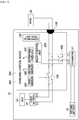
- FIG. 5 is a block diagram illustrating the electric vehicle charging system to which the electric vehicle charging controller according to one embodiment of the present invention is applied.
- the EV 10 includes an ECU 12, the first battery 14, a second battery 16, a converter 17, and the above-described electric vehicle charging controller 100.
- the ECU 12 allows various parts such as an engine, an automatic transmission, an anti-lock braking system (ABS), and the like of the vehicle to be controlled by a computer and may be connected to and communicate with the charging apparatus 100 and/or the EVSE 20.
- ABS anti-lock braking system
- the ECU 12 may communicate with the EVSE 20 to transmit and receive the states of the electric vehicle, that is, the charging state, the standby state, or the driving state.
- the first battery 14 is a high voltage battery that supplies a driving voltage to a driving unit of the vehicle, such as a motor (not shown), through an inverter (not shown). Such a first battery 14 may be charged through the EVSE 20 and the charging apparatus 100 and may also be charged through regenerative energy and/or engine operation of the vehicle. For example, the first battery 14 may have a first voltage capacity. However, when an abnormality in at least one of a plurality of battery cells constituting the first battery 14 is sensed by a battery management system (BMS) of the first battery 14, the first battery 14 may interrupt a circuit, and thus a voltage output from the first battery 14 may be 0 V.
- BMS battery management system
- the second battery 16 supplies a driving voltage to an electrical load such as a sensor, a microcontroller (MCU), a relay, and the like of the vehicle and may be generally composed of a low-voltage battery of approximately DC 12 V to 24 V.
- an electrical load such as a sensor, a microcontroller (MCU), a relay, and the like of the vehicle and may be generally composed of a low-voltage battery of approximately DC 12 V to 24 V.
- Such a second battery 16 may constantly apply a converted voltage to the charging apparatus 100 through the converter 17.
- the second battery 16 may apply a fifth voltage to the charging apparatus 100 through the converter 17.
- the converter 17 is composed of either an insulated gate bipolar transistor (IGBT) or a field-effect transistor (FET), which is a power semiconductor switching element, and is switched according to the control signal applied from the charging apparatus 100 to perform DC/DC converting in which a voltage is increased or decreased.
- IGBT insulated gate bipolar transistor
- FET field-effect transistor
- Such a converter 17 may be connected to the high voltage line through the switch 400, and the switch 400 may be switched according to the control signal of the charging apparatus 100.
- the second voltage value measured by the first sensor 210 is similar or identical to the voltage applied to the high voltage line from the first battery 14
- the third voltage value measured through the second sensor 220 is similar or identical to the voltage applied to the high voltage line from the second battery 16 through the converter 17.
- the voltage applied to the high voltage line from the first battery 14 may be set to 0 V or 60 V, and the voltage applied to the high voltage line through the converter 17 from the second battery 16 may be set to 24 V.
- the fourth voltage value may be set to a value in a range of 1/3 (20 V) to 1/2 (30 V) of the first voltage (60 V) that is the voltage of the first battery 14.
- the fourth voltage value may be set to 20 V.
- the setting of such a voltage value is merely described by way of example for the convenience of description and may be appropriately changed according to various embodiments, and the present invention is not specifically limited thereto.
- the difference between the second voltage value and the third voltage value may be measured as 24 V to 36 V, which is greater than 20 V that is the set fourth voltage value, and thus the relay 300 may be diagnosed as being normally turned off regardless of whether the first battery 14 is in a normal state (60 V) or a defective state (0 V).
- the control unit controls the relay 300 to be turned off, if the relay 300 is not normally turned off due to the welding of the relay 300, a point at which the voltage is measured by the first sensor 210 is electrically connected to a point at which the voltage is measured by the second sensor 220 so that the difference between the second voltage value and the third voltage value may be measured as a value within 5 V, which is less than 20 V that is the set fourth voltage value, and thus the relay 300 may be diagnosed as being welded regardless of whether the first battery 14 is in a normal state (60 V) or a defective state (0 V).
- a fifth voltage value and the fourth voltage value are set to a value of 1/2 (30 V) of the first voltage (60 V) that is the voltage of the first battery 14.
- the control unit controls the relay 300 to be turned off
- the difference between the second voltage value and the third voltage value may be measured as 30 V, which is greater than or equal to 30 V that is the set fourth voltage value, and thus the relay 300 may be diagnosed as being normally turned off regardless of whether the first battery 14 is in a normal state (60 V) or a defective state (0 V).
- the control unit controls the relay 300 to be turned off, if the relay 300 is not normally turned off due to the welding of the relay 300, a point at which the voltage is measured by the first sensor 210 is electrically connected to a point at which the voltage is measured by the second sensor 220 so that the difference between the second voltage value and the third voltage value may be measured as a value within 5 V, which is less than 30 V that is the set fourth voltage value, and thus the relay 300 may be determined as being welded regardless of whether the first battery 14 is in a normal state (60 V) or a defective state (0 V).
- the determination unit 240 may transmit and hold a relay-off signal to the relay 300 through the relay control unit 250 so that the remaining one relay 300 is turned off and transmit a message regarding whether the relay 300 is welded to a user through the communication unit 120.
- the determination unit 240 is switched to the sleep mode and does not determine whether the relay 300 is welded and thus turns off the switch 400 through the relay control unit 250 so that the voltage supplied from the second battery 16 may not be applied to the high voltage line.
- FIG. 6 is a block diagram illustrating an electric vehicle charging system to which an electric vehicle charging controller according to another embodiment of the present invention is applied.
- the electric vehicle charging controller 100 further includes a third sensor 230 and a fuse 500.
- the fuse 500 is disposed at a rear end of a contact to which a third voltage is applied through a switch 400 in a high voltage line.
- the third sensor 230 measures a voltage at a point between the fuse 500 and an inlet 150 in the high voltage line. That is, the third sensor 230 may measure a value (level) of a sixth voltage applied to a point after the fuse 500 at a rear end of a relay 300. Meanwhile, a determination unit 240 compares the difference between voltage values of a front end and a rear end of the fuse 500 obtained through a second sensor 220 and the third sensor 230 with a preset seventh voltage to determine whether the fuse 500 is blown.
- the determination unit 240 determines that the fuse 500 is normal, and on the contrary, when the difference between the third voltage value and the sixth voltage value is greater than the seventh voltage, the determination unit 240 determines that the fuse 500 is blown.
- the third voltage value measured through the second sensor 220 is similar or identical to the voltage applied to the high voltage line from the second battery 16 through the converter 17, and the sixth voltage value measured through the third sensor 230 may have a predetermined difference of approximately 5 V or less from the third voltage value.
- the voltage applied to the high voltage line from the second battery 16 through the converter 17 may be set to 24 V.
- the seventh voltage may be set to 5 V that is a predetermined voltage difference due to the fuse 500.
- the setting of such a voltage value is merely described by way of example for the convenience of description and may be appropriately changed according to the performance of the fuse 500, and the present invention is not specifically limited thereto.
- the difference between the third voltage value and the sixth voltage value may be measured as a value within 5 V, which is within a range of the set seventh voltage value, and thus the fuse 500 may be determined to be normal.
- the point at which the voltage is measured by the second sensor 220 is electrically blocked from the point at which the voltage is measured by the third sensor 230 so that the difference between the third voltage value and the sixth voltage value has a great difference value exceeding 5 V, which is less than 5 V that is the set seventh voltage value and thus the fuse 500 is determined to be blown.
- the determination unit 240 holds a relay-off signal transmitted to the relay 300 using a relay control unit 250 and transmits a message regarding whether the fuse 500 is blown to the user through a communication unit 120.
- the relay control unit 250 controls the operation of each of the relay 300 and the switch 400 that is connected to the converter 17 and controls turning each of the relay 300 and the switch 400 on or off according to the determination of the determination unit 240.
Landscapes
- Engineering & Computer Science (AREA)
- Power Engineering (AREA)
- Transportation (AREA)
- Mechanical Engineering (AREA)
- Physics & Mathematics (AREA)
- General Physics & Mathematics (AREA)
- Life Sciences & Earth Sciences (AREA)
- Sustainable Development (AREA)
- Sustainable Energy (AREA)
- Chemical & Material Sciences (AREA)
- Combustion & Propulsion (AREA)
- Charge And Discharge Circuits For Batteries Or The Like (AREA)
- Electric Propulsion And Braking For Vehicles (AREA)
Abstract
Description
- An embodiment relates to an electric vehicle charging controller.
- Eco-friendly vehicles, such as electric vehicles (EVs) or plug-in hybrid electric vehicles (PHEVs), use electric vehicle supply equipment (EVSE) installed at supplies (charging stations) to charge batteries.
- To this end, an electric vehicle charging controller (EVCC) is installed in the EV and communicates with the EV and the EVSE to control charging of the EV.
- For example, when the EVCC receives a signal for instructing to start charging from the EV, the EVCC may control to start the charging, and when the EVCC receives a signal for instructing to finish charging from the EV, the EVCC may control to finish the charging.
- Here, the EV may be charged through a slow charging method or fast charging method. When slow charging is performed, a charging time period of about seven hours is needed, and when fast charging is performed, a charging time period of about thirty minutes is needed.
- Meanwhile, a current of an EV battery is interrupted by a relay, and when an overcurrent flows through the relay according to a load of the vehicle while charging the battery, a phenomenon may occur in which the relay is welded. When the relay is welded as described above, the battery may be over discharged, and in this case, the battery may be left in an over discharged state and thus a problem may occur in which the battery may no longer be used.
- An embodiment is directed to providing an electric vehicle charging controller which allows welding of a relay to be easily diagnosed.
- An embodiment is also directed to providing an electric vehicle charging controller which allows over-discharge of a battery to be prevented.
- Objectives to be solved by embodiments are not limited to the above-described objectives and will include objectives and effectives which can be identified by solutions for the objectives and the embodiments described below.
- One aspect of the present invention provides an electric vehicle charging controller including a first sensor configured to measure a second voltage value between a first battery having a first voltage value and a relay in a high voltage line connected to electric vehicle supply equipment, a second sensor configured to measure a third voltage value between the electric vehicle supply equipment and the relay in the high voltage line, and a control unit configured to control turning the relay on or off, wherein if a difference between the second voltage value and the third voltage value is less than a preset fourth voltage value when the control unit applies a voltage of a second battery between the relay and the electric vehicle supply equipment in the high voltage line after controlling the relay to be turned off, the control unit determines that the relay is malfunctioning.
- The malfunctioning of the relay may be a state in which the relay is welded.
- The control unit may include a determination unit that determines whether the relay is malfunctioning.
- When it is determined that the relay is malfunctioning, the control unit may transmit an off-signal to the relay again.
- The electric vehicle charging controller may further include a converter disposed between the high voltage line and the second battery, and a switch disposed between the converter and the high voltage line, wherein a fixed fifth voltage value may be applied to the high voltage line through the converter.
- The electric vehicle charging controller may further include a communication unit configured to communicate with an electronic control unit (ECU) of an electric vehicle, wherein the communication unit receives state information related to a charging state, a standby state, and a driving state of the electric vehicle from the ECU.
- The relay control unit may transmit an off-signal to the switch when the electric vehicle is in the charging state, and the relay control unit may transmit an on-signal to the switch when the electric vehicle is in the standby state or the driving state.
- The ECU may communicate with the electric vehicle supply equipment to transmit the state information related to the charging state, the standby state, and the driving state of the vehicle to the communication unit.
- The fifth voltage value may set to a value in a range of 1/3 to 1/2 of the first voltage value.
- The fourth voltage value may set to a value of 1/3 of the first voltage value.
- The fifth voltage value may be set to a value of 1/2 of the first voltage value.
- The fourth voltage value may be set to be equal to the fifth voltage value.
- The electric vehicle charging controller may further include a fuse installed between the electric vehicle supply equipment and a contact to which the fifth voltage is applied in the high voltage line.
- The electric vehicle charging controller may further include a third sensor configured to measure a sixth voltage value between the electric vehicle supply equipment and the fuse in the high voltage line, wherein when a difference between the third voltage value and the sixth voltage value is measured to be greater than or equal to a preset seventh voltage value, the diagnosis unit determines that the fuse is blown.
- According to embodiments, welding of a relay can be easily diagnosed by applying a low voltage (LV) for a vehicle to a high voltage line through which charging is performed.
- Further, over-discharge of a battery can be prevented by interrupting a relay according to whether the relay is welded.
- Various and useful advantages and effects of the present invention are not limited to the above-described advantages and may be more easily understood in the course of describing specific embodiments of the present invention.
-
-
FIG. 1 is a set of exemplary views illustrating a normal OFF operation and a welded state of an electric vehicle relay. -
FIGS. 2 and 3 are exemplary views illustrating an electric vehicle charging system according to one embodiment of the present invention. -
FIG. 4 is a block diagram illustrating an electric vehicle charging controller according to one embodiment of the present invention. -
FIG. 5 is a block diagram illustrating the electric vehicle charging system to which the electric vehicle charging controller according to one embodiment of the present invention is applied. -
FIG. 6 is a block diagram illustrating an electric vehicle charging system to which an electric vehicle charging controller according to another embodiment of the present invention is applied. - Hereinafter, exemplary embodiments of the present invention will be described in detail with reference to the drawings.
- However, the technical spirit of the present invention is not limited to some embodiments which will be described herein and may be implemented using various other embodiments, and at least one element of the embodiments may be selectively coupled, substituted, and used to implement the technical spirit within the range of the technical spirit.
- Further, unless clearly and specifically defined otherwise by context, all terms (including technical and scientific terms) used herein can be interpreted as having customary meanings to those skilled in the art, and meanings of generally used terms, such as those defined in commonly used dictionaries, will be interpreted by considering contextual meanings of the related technology.
- Further, the terms used in the embodiments of the present invention are provided only to describe embodiments of the present invention and not to limit the present invention.
- In the present specification, the singular forms include the plural forms unless the context clearly indicates otherwise, and the phrase "at least one element (or one or more elements) of an element A, an element B, and an element C" should be understood as including the meaning of at least one of all combinations being obtained by combining the element A, the element B, and the element C.
- Further, in describing elements of the embodiments of the present invention, the terms such as first, second, A, B, (a), (b), and the like may be used.
- These terms are merely for distinguishing one element from other elements, and the essential, order, sequence, and the like of corresponding elements are not limited by the terms.
- Also, when it is stated that one element is "connected," or "coupled" to another, the element may not only be directly connected or coupled to the other element but may also be connected or coupled to the other element with another intervening element.
- Further, when an element is described as being formed or disposed "on (above)" or "under (below)" another element, the term "on (above)" or "under (below)" includes both of a case in which two elements are in direct contact with each other and a case in which one or more elements are (indirectly) disposed between two elements. In addition, when one element is described as being disposed "on or under" another element, such a description may include a case in which the one element is disposed at an upper side or a lower side with respect to another element.
- Hereinafter, one embodiment of the present invention will be described in detail with reference to the accompanying drawings so that those skilled in the art may easily perform the present invention.
-
FIG. 1 is a set of exemplary views illustrating a normal OFF operation and a welded state of an electric vehicle relay. - First, when a more detailed description is given to welding of a relay, contacts of the relay include a fixed contact and a moving contact, and the state in which these two contacts are stuck together by an arc generated between the fixed contact and the moving contact and thus turning the relay on or off is not controlled is referred to as a malfunction of the relay, for example, a welded state of the relay.
- In a vehicle in which two
relays relay 3 is welded, as shown inFIG. 1 , the contact of therelay 3 in which the welding is generated is not released even in an ignition (IG)-off state in which both relays should be in an off state, and thus therelay 3 is not turned off. - When the relay control is impossible as described above, an inherent function/purpose of high voltage may not be achieved, and a secondary accident such as an electric shock, a fire, or the like is inevitably generated as well as a primary accident due to the inability to secure insulation during an accident such as a collision.
- For example, when the off-control of the
relays high voltage battery 1 is exposed to the outside, an electric closed loop is formed through the high voltage battery and a human body so that current runs therethrough, and thus the human body is exposed to various types of electric shock risks. - In other words, the human body may lead to an electric shock risk in a direct contact state in which the human body comes into contact with high voltage positive (+) and negative (-) terminals at the same time, an electric shock risk in a direct/indirect contact state in which the human body comes into contact with any one terminal under a condition in which insulation between a vehicle body and wires is broken or comes into contact with the terminal and a high voltage part, in which insulation is broken, at the same time, or an electric shock risk in an indirect contact state in which the human body comes into contact with the high voltage part in which insulation is broken under the condition in which the insulation between the vehicle body and the wires is broken or comes into contact with two high voltage parts, in which insulation is broken, at the same time.
-
FIGS. 2 and 3 are exemplary views illustrating an electric vehicle charging system according to one embodiment of the present invention. - Referring to
FIGS. 2 and 3 , an electric vehicle (EV) 10 may be charged from an electric vehicle supply equipment (EVSE) 20. To this end, acharging cable 22 connected to the EVSE 20 may be connected to an inlet of theEV 10. Here, the EVSE 20 is equipment that supplies an alternating current (AC) or DC, and may be disposed at a supply or home, or may also be portably implemented. The EVSE 20 may also be referred to as a supply, an AC supply, a DC supply, a socket-outlet, or the like. - An electric vehicle charging controller (EVCC) 100 is installed in and connected to the
EV 10. For example, the EVCC 100 may be installed in a trunk of theEV 10, but the present invention is not limited thereto. - The EV 10 may be charged in a supply in which the EVSE 20 is disposed. To this end, the charging
cable 22 connected to theEVSE 20 may be connected to aninlet 150 of theEV 10. - A charging mode of the
EV 10 may be classified into several types according to a connection method between the EVSE 20 and theEV 10. For example, the charging mode may be classified intoMode 1 in which theEV 10 is connected to an AC supply network using a standardized socket-outlet,Mode 2 in which theEV 10 is connected to the AC supply network using a control pilot (CP) function and a protection system against electric shock between theEV 10 and a plug or a part of an in-cable control box,Mode 3 in which theEV 10 is permanently connected to the AC supply network using a dedicated EVSE, in which the CP function extends to control equipment in the EVSE, and Mode 4 in which theEV 10 is connected to the supply network using a DC EV charging station (e.g., off-board charger) in which the CP function extends to a DC EV charging station. - According to one embodiment of the present invention, a malfunction of a relay, for example, welding of the relay, in the EVCC of the EV is diagnosed in states other than a charging state, and when the welding is diagnosed, the relay is quickly turned off.
-
FIG. 4 is a block diagram illustrating an electric vehicle charging controller according to one embodiment of the present invention. - Referring to
FIGS. 2 to 4 , an electricvehicle charging controller 100 according to one embodiment of the present invention includes acommunication unit 120, a chargingcontrol device 200, arelay 300, and aswitch 400. - The
communication unit 120 may transmit and receive signals between theEVSE 20, the chargingcontrol device 200, and an electric power control unit (ECU) of theEV 10 and receive signals for controlling charging of afirst battery 14 from the ECU. In addition, thecommunication unit 120 may also transfer control signals of the chargingcontrol device 200. - Such a
communication unit 120 may have a plurality of communication channels, and the plurality of communication channels may operate under different protocols. For example, one communication channel may operate under a protocol that supports power line communication (PLC), pulse width modulation (PWM), or both thereof, and another communication channel may operate under a protocol that supports a controller area network (CAN). - The charging
control device 200 is connected to each of theEV 10 and theEVSE 20. The chargingcontrol device 200 may be connected to each of theEV 10 and theEVSE 20 through a plurality of pins. - For example, the charging
control device 200 may include 20 pins connected to theEVSE 20 and communicate with theEVSE 20 through the 20 pins. For example, among the 20 pins, one pin may be a pin for a CP port for receiving a CP signal from theEVSE 20, another pin may be a pin for a proximity detection (PD) port for detecting whether a charging cable connector is close, and still another pin may be a pin for a protective earth (PE) port connected to the ground of theEVSE 20. Yet another pin among the 20 pins may be a pin for driving a motor to open a flap of a charge port, still yet another pin thereof may be a pin for sensing a motor, still yet another pin thereof may be a pin for sensing a temperature, still yet another pin thereof may be a pin for sensing a light-emitting diode (LED), and still yet another pin thereof may be a pin for CAN communication. However, the number and functions of the pins are not limited thereto and may be variously changed. - In addition, the charging
control device 200 includes twelve pins connected to theEV 10 and may communicate with theEV 10 through the twelve pins. For example, among the twelve pins, one pin may be a pin for a line of a voltage applied from a collision detection sensor in theEV 10, another pin may be a battery pin in theEV 10, still another pin may be a pin for CAN communication, yet another pin may be a pin connected to the ground, and still yet another pin may be a high voltage protection pin. However, the number and functions of the pins are not limited thereto and may be variously changed. - Two high voltage lines of the
EVSE 20 supply power to the first battery of theEV 10 through therelay 300 of the chargingapparatus 100, and here, turning the high voltage lines on or off may be controlled by the chargingcontrol device 200. - That is, the charging
control device 200 may communicate with the ECU of theEV 10 through thecommunication unit 120 and control therelay 300 configured to transfer the power supplied from theEVSE 20 to the first battery of theEV 10 according to the signals received from each of theEV 10 and theEVSE 20. - Here, the charging
control device 200 may include afirst sensor 210, asecond sensor 220, and a control unit, and the control unit may include adetermination unit 240 and arelay control unit 250. In the present specification, thedetermination unit 240 may also be referred to as a diagnosis unit. - The
first sensor 210 measures a voltage of a first point at a front end of therelay 300 in a high voltage line connecting the first battery to the inlet to be connected to theEVSE 20. That is, thefirst sensor 210 may measure a value (level) of a second voltage applied to the front end of therelay 300. - Here, the front end of the
relay 300 may be defined as a point between the first battery and therelay 300 of theEV 10. - The
second sensor 220 measures a voltage of a second point at a rear end of therelay 300 in the high voltage line. That is, thesecond sensor 220 may measure a value (level) of a third voltage applied to the rear end of therelay 300. - Here, the rear end of the
relay 300 may be defined as a point between therelay 300 and the charge port of theEV 10. - The control unit included in the charging
control device 200 according to one embodiment of the present invention controls turning therelay 300 on or off and determines the malfunction of the relay using the value of the voltage measured at each point of the high voltage line after controlling therelay 300 to be turned off. - That is, the control unit controls the
relay 300 to be turned off, and then compares/analyzes the value of the voltage measured at each point of the high voltage line through thefirst sensor 210 and thesecond sensor 220 to determine whether therelay 300 is malfunctioning, that is, whether therelay 300 is welded, and transmits an off-operation signal to therelay 300 again when it is determined that therelay 300 is malfunctioning. Here, thedetermination unit 240 may determine whether therelay 300 is malfunctioning, and therelay control unit 250 may transmit the off-operation signal to therelay 300. - The
determination unit 240 diagnoses whether therelay 300 is malfunctioning, that is, whether therelay 300 is welded in states of theEV 10 other than a charging state among the charging state, a standby state, and a driving state of theEV 10 received through thecommunication unit 120, and when theEV 10 is in the charging state, thedetermination unit 240 is switched to a sleep mode. - More specifically, the control unit controls the
relay 300 to be turned off, and then compares the difference between the voltage values of the front end and the rear end of therelay 300 obtained through thefirst sensor 210 and thesecond sensor 220 with a preset fourth voltage value to determine whether therelay 300 is malfunctioning, that is, whether therelay 300 is welded. - For example, when a voltage of a second battery is applied to the high voltage line between the
relay 300 and theEVSE 20 in a state in which therelay 300 is controlled to be turned off, thedetermination unit 240 determines that therelay 300 is normal when the difference between the second voltage value measured by thefirst sensor 210 and the third voltage value measured by thesecond sensor 220 is greater than or equal to the preset fourth voltage, and on the contrary, determines that therelay 300 is malfunctioning, that is, therelay 300 is welded, when the difference between the second voltage value and the third voltage value is less than the fourth voltage. - The
switch 400 interrupts the connection between the high voltage line and a converter that is configured to fix and output the voltage of the second battery of theEV 10 and may be integrally formed with the converter and may be implemented as an internal configuration of the chargingcontrol device 200.FIG. 5 is a block diagram illustrating the electric vehicle charging system to which the electric vehicle charging controller according to one embodiment of the present invention is applied. - Hereinafter, the operation of the charging
control device 200 of the electricvehicle charging controller 100 will be described through the electric vehicle charging system to which the electric vehicle charging controller according to one embodiment of the present invention is applied. - Referring to
FIG. 5 , theEV 10 includes anECU 12, thefirst battery 14, asecond battery 16, aconverter 17, and the above-described electricvehicle charging controller 100. - The
ECU 12 allows various parts such as an engine, an automatic transmission, an anti-lock braking system (ABS), and the like of the vehicle to be controlled by a computer and may be connected to and communicate with the chargingapparatus 100 and/or theEVSE 20. - In particular, the
ECU 12 may communicate with theEVSE 20 to transmit and receive the states of the electric vehicle, that is, the charging state, the standby state, or the driving state. - The
first battery 14 is a high voltage battery that supplies a driving voltage to a driving unit of the vehicle, such as a motor (not shown), through an inverter (not shown). Such afirst battery 14 may be charged through theEVSE 20 and thecharging apparatus 100 and may also be charged through regenerative energy and/or engine operation of the vehicle. For example, thefirst battery 14 may have a first voltage capacity. However, when an abnormality in at least one of a plurality of battery cells constituting thefirst battery 14 is sensed by a battery management system (BMS) of thefirst battery 14, thefirst battery 14 may interrupt a circuit, and thus a voltage output from thefirst battery 14 may be 0 V. - The
second battery 16 supplies a driving voltage to an electrical load such as a sensor, a microcontroller (MCU), a relay, and the like of the vehicle and may be generally composed of a low-voltage battery of approximately DC 12 V to 24 V. - Such a
second battery 16 may constantly apply a converted voltage to thecharging apparatus 100 through theconverter 17. For example, thesecond battery 16 may apply a fifth voltage to thecharging apparatus 100 through theconverter 17. - The
converter 17 is composed of either an insulated gate bipolar transistor (IGBT) or a field-effect transistor (FET), which is a power semiconductor switching element, and is switched according to the control signal applied from the chargingapparatus 100 to perform DC/DC converting in which a voltage is increased or decreased. - Such a
converter 17 may be connected to the high voltage line through theswitch 400, and theswitch 400 may be switched according to the control signal of the chargingapparatus 100. - Here, when the power is not supplied from the EVSE 20 and the
relay 300 is normally turned off, the second voltage value measured by thefirst sensor 210 is similar or identical to the voltage applied to the high voltage line from thefirst battery 14, and the third voltage value measured through thesecond sensor 220 is similar or identical to the voltage applied to the high voltage line from thesecond battery 16 through theconverter 17. - For example, the voltage applied to the high voltage line from the
first battery 14 may be set to 0 V or 60 V, and the voltage applied to the high voltage line through theconverter 17 from thesecond battery 16 may be set to 24 V. In addition, the fourth voltage value may be set to a value in a range of 1/3 (20 V) to 1/2 (30 V) of the first voltage (60 V) that is the voltage of thefirst battery 14. For example, as an example, the fourth voltage value may be set to 20 V. However, the setting of such a voltage value is merely described by way of example for the convenience of description and may be appropriately changed according to various embodiments, and the present invention is not specifically limited thereto. - That is, when the control unit controls the
relay 300 to be turned off, if therelay 300 is normally turned off, the difference between the second voltage value and the third voltage value may be measured as 24 V to 36 V, which is greater than 20 V that is the set fourth voltage value, and thus therelay 300 may be diagnosed as being normally turned off regardless of whether thefirst battery 14 is in a normal state (60 V) or a defective state (0 V). - However, when the control unit controls the
relay 300 to be turned off, if therelay 300 is not normally turned off due to the welding of therelay 300, a point at which the voltage is measured by thefirst sensor 210 is electrically connected to a point at which the voltage is measured by thesecond sensor 220 so that the difference between the second voltage value and the third voltage value may be measured as a value within 5 V, which is less than 20 V that is the set fourth voltage value, and thus therelay 300 may be diagnosed as being welded regardless of whether thefirst battery 14 is in a normal state (60 V) or a defective state (0 V). - Here, when the phenomenon of resistance or voltage fluctuation is ignored, it is easy for the calculation and the diagnosis that a fifth voltage value and the fourth voltage value are set to a value of 1/2 (30 V) of the first voltage (60 V) that is the voltage of the
first battery 14. - That is, when the control unit controls the
relay 300 to be turned off, if therelay 300 is normally turned off, the difference between the second voltage value and the third voltage value may be measured as 30 V, which is greater than or equal to 30 V that is the set fourth voltage value, and thus therelay 300 may be diagnosed as being normally turned off regardless of whether thefirst battery 14 is in a normal state (60 V) or a defective state (0 V). - However, when the control unit controls the
relay 300 to be turned off, if therelay 300 is not normally turned off due to the welding of therelay 300, a point at which the voltage is measured by thefirst sensor 210 is electrically connected to a point at which the voltage is measured by thesecond sensor 220 so that the difference between the second voltage value and the third voltage value may be measured as a value within 5 V, which is less than 30 V that is the set fourth voltage value, and thus therelay 300 may be determined as being welded regardless of whether thefirst battery 14 is in a normal state (60 V) or a defective state (0 V). - Meanwhile, when the
determination unit 240 determines that therelay 300 is malfunctioning, that is, is welded, thedetermination unit 240 may transmit and hold a relay-off signal to therelay 300 through therelay control unit 250 so that the remaining onerelay 300 is turned off and transmit a message regarding whether therelay 300 is welded to a user through thecommunication unit 120. - Meanwhile, as described above, when the
EV 10 is in the charging state, thedetermination unit 240 is switched to the sleep mode and does not determine whether therelay 300 is welded and thus turns off theswitch 400 through therelay control unit 250 so that the voltage supplied from thesecond battery 16 may not be applied to the high voltage line. -
FIG. 6 is a block diagram illustrating an electric vehicle charging system to which an electric vehicle charging controller according to another embodiment of the present invention is applied. - Hereinafter, the operation of a charging
control device 200 of an electricvehicle charging controller 100 will be described through the electric vehicle charging system to which the electric vehicle charging controller according to another embodiment of the present invention is applied. - Here, in the electric vehicle charging system of
FIG. 6 , the same reference numerals are used for the same configuration as the electric vehicle charging system ofFIG. 5 , and thus a repetitive description thereof will be omitted below. - Referring to
FIG. 6 , in the electric vehicle charging system according to another embodiment of the present invention, the electricvehicle charging controller 100 further includes athird sensor 230 and afuse 500. - The
fuse 500 is disposed at a rear end of a contact to which a third voltage is applied through aswitch 400 in a high voltage line. - Further, the
third sensor 230 measures a voltage at a point between thefuse 500 and aninlet 150 in the high voltage line. That is, thethird sensor 230 may measure a value (level) of a sixth voltage applied to a point after thefuse 500 at a rear end of arelay 300. Meanwhile, adetermination unit 240 compares the difference between voltage values of a front end and a rear end of thefuse 500 obtained through asecond sensor 220 and thethird sensor 230 with a preset seventh voltage to determine whether thefuse 500 is blown. - For example, when the difference between a third voltage value and the sixth voltage value is less than or equal to the seventh voltage, the
determination unit 240 determines that thefuse 500 is normal, and on the contrary, when the difference between the third voltage value and the sixth voltage value is greater than the seventh voltage, thedetermination unit 240 determines that thefuse 500 is blown. - Here, when power is not supplied from the
EVSE 20, therelay 300 is normally turned off, and thefuse 500 is normal, the third voltage value measured through thesecond sensor 220 is similar or identical to the voltage applied to the high voltage line from thesecond battery 16 through theconverter 17, and the sixth voltage value measured through thethird sensor 230 may have a predetermined difference of approximately 5 V or less from the third voltage value. - For example, like in the above-described embodiment, the voltage applied to the high voltage line from the
second battery 16 through theconverter 17 may be set to 24 V. In addition, the seventh voltage may be set to 5 V that is a predetermined voltage difference due to thefuse 500. However, the setting of such a voltage value is merely described by way of example for the convenience of description and may be appropriately changed according to the performance of thefuse 500, and the present invention is not specifically limited thereto. - That is, when the
fuse 500 is normal, the difference between the third voltage value and the sixth voltage value may be measured as a value within 5 V, which is within a range of the set seventh voltage value, and thus thefuse 500 may be determined to be normal. - However, when the
fuse 500 is blown, the point at which the voltage is measured by thesecond sensor 220 is electrically blocked from the point at which the voltage is measured by thethird sensor 230 so that the difference between the third voltage value and the sixth voltage value has a great difference value exceeding 5 V, which is less than 5 V that is the set seventh voltage value and thus thefuse 500 is determined to be blown. - Meanwhile, when it is determined that the
fuse 500 is blown, thedetermination unit 240 holds a relay-off signal transmitted to therelay 300 using arelay control unit 250 and transmits a message regarding whether thefuse 500 is blown to the user through acommunication unit 120. - The
relay control unit 250 controls the operation of each of therelay 300 and theswitch 400 that is connected to theconverter 17 and controls turning each of therelay 300 and theswitch 400 on or off according to the determination of thedetermination unit 240. - While the embodiments have been mainly described, the embodiments are only examples but do not limit the present invention, and it may be known to those skilled in the art that various modifications and applications, which have not been described above, may be made without departing from the essential properties of the embodiments. For example, each component specified in the embodiments may be modified and implemented. In addition, it is to be understood that differences related to such modifications and applications fall within the scope of the present invention defined in the appended claims.
Claims (14)
- An electric vehicle charging controller comprising:a first sensor configured to measure a second voltage value between a first battery having a first voltage value and a relay in a high voltage line connected to electric vehicle supply equipment;a second sensor configured to measure a third voltage value between the electric vehicle supply equipment and the relay in the high voltage line; anda control unit configured to control turning the relay on or off,wherein if a difference between the second voltage value and the third voltage value is less than a preset fourth voltage value when the control unit applies a voltage of a second battery between the relay and the electric vehicle supply equipment in the high voltage line after controlling the relay to be turned off, the control unit determines that the relay is malfunctioning.
- The electric vehicle charging controller of claim 1, wherein the malfunctioning of the relay is a state in which the relay is welded.
- The electric vehicle charging controller of claim 1, wherein the control unit includes a determination unit that determines whether the relay is malfunctioning.
- The electric vehicle charging controller of claim 1, wherein, when it is determined that the relay is malfunctioning, the control unit transmits an off-signal to the relay again.
- The electric vehicle charging controller of claim 1, further comprising:a converter disposed between the high voltage line and the second battery; anda switch disposed between the converter and the high voltage line,wherein a fixed fifth voltage value is applied to the high voltage line through the converter.
- The electric vehicle charging controller of claim 5, further comprising a communication unit configured to communicate with an electronic control unit (ECU) of an electric vehicle, wherein the communication unit receives state information related to a charging state, a standby state, and a driving state of the electric vehicle from the ECU.
- The electric vehicle charging controller of claim 6, wherein
the control unit transmits an off-signal to the switch when the electric vehicle is in the charging state, and
the control unit transmits an on-signal to the switch when the electric vehicle is in the standby state or the driving state. - The electric vehicle charging controller of claim 6, wherein the ECU communicates with the electric vehicle supply equipment to transmit the state information related to the charging state, the standby state, and the driving state of the electric vehicle to the communication unit.
- The electric vehicle charging controller of claim 1, wherein the fifth voltage value is set to a value in a range of 1/3 to 1/2 of the first voltage value.
- The electric vehicle charging controller of claim 9, wherein the fourth voltage value is set to a value of 1/3 of the first voltage value.
- The electric vehicle charging controller of claim 1, wherein the fifth voltage value is set to a value of 1/2 of the first voltage value.
- The electric vehicle charging controller of claim 11, wherein the fourth voltage value is set to be equal to the fifth voltage value.
- The electric vehicle charging controller of claim 1, further comprising a fuse installed between the electric vehicle supply equipment and a contact to which a voltage having the fifth voltage value is applied in the high voltage line.
- The electric vehicle charging controller of claim 13, further comprising a third sensor configured to measure a sixth voltage value between the electric vehicle supply equipment and the fuse in the high voltage line, wherein when a difference between the third voltage value and the sixth voltage value is measured to be greater than or equal to a preset seventh voltage value, the control unit determines that the fuse is blown.
Applications Claiming Priority (2)
| Application Number | Priority Date | Filing Date | Title |
|---|---|---|---|
| KR1020170134514A KR102516435B1 (en) | 2017-10-17 | 2017-10-17 | Electric Vehicle Charging Controller |
| PCT/KR2018/012263 WO2019078616A2 (en) | 2017-10-17 | 2018-10-17 | Electric vehicle charging apparatus |
Publications (2)
| Publication Number | Publication Date |
|---|---|
| EP3699013A2 true EP3699013A2 (en) | 2020-08-26 |
| EP3699013A4 EP3699013A4 (en) | 2021-07-21 |
Family
ID=66174049
Family Applications (1)
| Application Number | Title | Priority Date | Filing Date |
|---|---|---|---|
| EP18868462.5A Pending EP3699013A4 (en) | 2017-10-17 | 2018-10-17 | ELECTRIC VEHICLE CHARGING DEVICE |
Country Status (4)
| Country | Link |
|---|---|
| US (1) | US11447031B2 (en) |
| EP (1) | EP3699013A4 (en) |
| KR (1) | KR102516435B1 (en) |
| WO (1) | WO2019078616A2 (en) |
Cited By (6)
| Publication number | Priority date | Publication date | Assignee | Title |
|---|---|---|---|---|
| US11358485B2 (en) * | 2020-02-04 | 2022-06-14 | Toyota Jidosha Kabushiki Kaisha | Vehicle |
| WO2022130010A1 (en) * | 2020-12-18 | 2022-06-23 | Brusa Elektronik Ag | Method and charging device for charging a high-voltage battery of an electric vehicle with protective earth and insulation monitoring |
| EP4116138A3 (en) * | 2021-06-16 | 2023-03-22 | Defa AS | A charging assembly and method |
| EP4245591A1 (en) * | 2022-03-16 | 2023-09-20 | Toyota Jidosha Kabushiki Kaisha | Relay drive control device, control method, and storage medium |
| EP4258317A1 (en) * | 2022-04-08 | 2023-10-11 | Schneider Electric Industries Sas | Relay monitoring device, dual power supply switching control device and relay monitoring method |
| EP4481986A3 (en) * | 2023-06-22 | 2025-05-07 | Kubota Corporation | Electric working machine and method of activating electric working machine |
Families Citing this family (24)
| Publication number | Priority date | Publication date | Assignee | Title |
|---|---|---|---|---|
| KR102690900B1 (en) * | 2017-02-08 | 2024-08-02 | 엘지이노텍 주식회사 | Charging control apparatus for electric vehicle |
| KR102603886B1 (en) * | 2018-02-13 | 2023-11-21 | 엘지이노텍 주식회사 | Charging control apparatus for electrical vehicle |
| KR101996603B1 (en) * | 2018-12-19 | 2019-07-04 | 중앙제어 주식회사 | Apparatus for Sensing Temperature of Electric Vehicle Charger |
| JP7200717B2 (en) * | 2019-02-06 | 2023-01-10 | トヨタ自動車株式会社 | Vehicle and welding diagnosis method |
| JP7200716B2 (en) * | 2019-02-06 | 2023-01-10 | トヨタ自動車株式会社 | Vehicle and welding diagnosis method |
| KR102730413B1 (en) * | 2019-05-08 | 2024-11-15 | 한국단자공업 주식회사 | Apparatus for diagnosing operation states of quick charge system in a electric vehcile |
| KR102753140B1 (en) * | 2019-10-31 | 2025-01-14 | 에스케이온 주식회사 | System for protecting battery |
| KR102326825B1 (en) * | 2020-01-23 | 2021-11-17 | (주)인피니티웍스 | High-speed battery charger for electric vehicle having parallel controller |
| KR102904692B1 (en) * | 2020-03-13 | 2025-12-29 | 엘지이노텍 주식회사 | Electric vehicle charging controller and apparatus for charging electric vehicle comprising the same |
| CN113759183B (en) * | 2020-06-02 | 2024-05-28 | 浙江安吉智电控股有限公司 | Self-checking method, device and computer storage medium |
| KR102264996B1 (en) * | 2020-08-18 | 2021-06-16 | 한국단자공업 주식회사 | Apparatus for sensing quick charge high voltage in an electrical vehicle |
| JP7269905B2 (en) * | 2020-09-28 | 2023-05-09 | 本田技研工業株式会社 | MOBILE BODY CONTROL DEVICE, CONTROL METHOD THEREOF, AND MOBILE BODY |
| WO2022082531A1 (en) * | 2020-10-21 | 2022-04-28 | 深圳欣锐科技股份有限公司 | Relay working state inspection system, apparatus and method, and reverse connection detection method |
| CN112440803B (en) * | 2020-11-10 | 2022-04-26 | 青岛鼎信通讯股份有限公司 | Redundancy monitoring method for series modules of medium-high voltage electric vehicle charging station |
| WO2022234436A1 (en) * | 2021-05-04 | 2022-11-10 | Accelerated Systems Inc. | Methods and systems for operating an electric vehicle |
| KR102534614B1 (en) * | 2021-05-13 | 2023-05-30 | 주식회사 일진정공 | Battery emergency charging method of electric special vehicle |
| KR102524933B1 (en) * | 2021-05-13 | 2023-04-27 | 주식회사 일진정공 | Battery charging system for an electric special vehicle and method of charging an electric special vehicle |
| JP7652101B2 (en) * | 2022-02-08 | 2025-03-27 | トヨタ自動車株式会社 | CHARGING/DISCHARGING DEVICE, VEHICLE, AND METHOD FOR CONTROLLING CHARGING/DISCHARGING DEVICE |
| CN115424443B (en) * | 2022-09-20 | 2024-04-26 | 安徽江淮汽车集团股份有限公司 | Vehicle abnormity monitoring method based on driving data |
| US20240317084A1 (en) * | 2023-03-20 | 2024-09-26 | Ford Global Technologies, Llc | Direct current fast charge monitoring and control |
| KR20240162930A (en) * | 2023-05-09 | 2024-11-18 | 엘지이노텍 주식회사 | Electric Vehicle Communication Controller Device |
| KR102856512B1 (en) * | 2024-01-16 | 2025-09-10 | (주)모던텍 | Electric vehicle charger that can stably charge electric vehicles with mutual potential differences |
| EP4686599A1 (en) * | 2024-08-01 | 2026-02-04 | LG Energy Solution, Ltd. | Battery management device for software-defined vehicle |
| CN119840467B (en) * | 2025-01-14 | 2025-11-21 | 重庆长安凯程汽车科技有限公司 | Branching charging equipment matched with charging gun |
Family Cites Families (13)
| Publication number | Priority date | Publication date | Assignee | Title |
|---|---|---|---|---|
| US7557583B2 (en) * | 2005-11-21 | 2009-07-07 | Gm Global Technology Operations, Inc. | System and method for monitoring an electrical power relay in a hybrid electric vehicle |
| JP4513812B2 (en) * | 2007-01-04 | 2010-07-28 | トヨタ自動車株式会社 | Vehicle power supply device and vehicle |
| JP5152338B2 (en) * | 2008-09-19 | 2013-02-27 | トヨタ自動車株式会社 | Non-contact charging device and non-contact power receiving device |
| KR101617292B1 (en) | 2010-08-02 | 2016-05-18 | 엘지전자 주식회사 | Electric vehicles and method for sub-battery charging control thereof |
| JP5621648B2 (en) * | 2011-02-16 | 2014-11-12 | トヨタ自動車株式会社 | Vehicle and vehicle control method |
| KR101332871B1 (en) * | 2012-05-22 | 2013-11-25 | 엘에스산전 주식회사 | Apparatus for relay monitoring of electric vehicle and method thereof |
| JP5772784B2 (en) * | 2012-10-19 | 2015-09-02 | トヨタ自動車株式会社 | Vehicle, power supply system, and control method for power supply system |
| JP6110355B2 (en) * | 2014-11-25 | 2017-04-05 | トヨタ自動車株式会社 | Fault diagnosis method for vehicle and voltage sensor |
| KR20170014666A (en) * | 2015-07-30 | 2017-02-08 | 엘에스산전 주식회사 | Recharging device for vehicle |
| JP2017073888A (en) * | 2015-10-07 | 2017-04-13 | トヨタ自動車株式会社 | vehicle |
| JP6713291B2 (en) * | 2016-02-05 | 2020-06-24 | 株式会社デンソーテン | Welding detection device and welding detection method |
| KR102051177B1 (en) * | 2016-10-19 | 2019-12-17 | 주식회사 엘지화학 | Apparatus and methode for switch diagnosis using voltage distribution |
| JP6867780B2 (en) * | 2016-10-28 | 2021-05-12 | 矢崎総業株式会社 | Semiconductor switch controller |
-
2017
- 2017-10-17 KR KR1020170134514A patent/KR102516435B1/en active Active
-
2018
- 2018-10-17 EP EP18868462.5A patent/EP3699013A4/en active Pending
- 2018-10-17 US US16/756,180 patent/US11447031B2/en active Active
- 2018-10-17 WO PCT/KR2018/012263 patent/WO2019078616A2/en not_active Ceased
Cited By (10)
| Publication number | Priority date | Publication date | Assignee | Title |
|---|---|---|---|---|
| US11358485B2 (en) * | 2020-02-04 | 2022-06-14 | Toyota Jidosha Kabushiki Kaisha | Vehicle |
| US20220266711A1 (en) * | 2020-02-04 | 2022-08-25 | Toyota Jidosha Kabushiki Kaisha | Vehicle |
| US11738655B2 (en) | 2020-02-04 | 2023-08-29 | Toyota Jidosha Kabushiki Kaisha | Vehicle |
| WO2022130010A1 (en) * | 2020-12-18 | 2022-06-23 | Brusa Elektronik Ag | Method and charging device for charging a high-voltage battery of an electric vehicle with protective earth and insulation monitoring |
| US11673482B2 (en) | 2020-12-18 | 2023-06-13 | Preh Gmbh | Method and charging device for charging a high-voltage battery of an electric vehicle |
| EP4116138A3 (en) * | 2021-06-16 | 2023-03-22 | Defa AS | A charging assembly and method |
| EP4245591A1 (en) * | 2022-03-16 | 2023-09-20 | Toyota Jidosha Kabushiki Kaisha | Relay drive control device, control method, and storage medium |
| US11901146B2 (en) | 2022-03-16 | 2024-02-13 | Toyota Jidosha Kabushiki Kaisha | Relay drive control device, control method, and storage medium |
| EP4258317A1 (en) * | 2022-04-08 | 2023-10-11 | Schneider Electric Industries Sas | Relay monitoring device, dual power supply switching control device and relay monitoring method |
| EP4481986A3 (en) * | 2023-06-22 | 2025-05-07 | Kubota Corporation | Electric working machine and method of activating electric working machine |
Also Published As
| Publication number | Publication date |
|---|---|
| WO2019078616A2 (en) | 2019-04-25 |
| KR102516435B1 (en) | 2023-03-31 |
| KR20190042889A (en) | 2019-04-25 |
| US11447031B2 (en) | 2022-09-20 |
| EP3699013A4 (en) | 2021-07-21 |
| WO2019078616A3 (en) | 2019-06-06 |
| US20200276908A1 (en) | 2020-09-03 |
Similar Documents
| Publication | Publication Date | Title |
|---|---|---|
| US11447031B2 (en) | Electric vehicle charging apparatus | |
| US11305657B2 (en) | Electric propulsion vehicle charging cable and power adapter attached to electric propulsion vehicle charging cable | |
| KR101616233B1 (en) | Charging/discharging device | |
| US11130420B2 (en) | System and method for charge contactor weld check | |
| US10476262B2 (en) | Dual-bus battery precharge circuit | |
| CN107804171B (en) | Vehicle high voltage interlock | |
| US20190184849A1 (en) | Charging device for electric vehicle | |
| CN106585421B (en) | A kind of Intelligent charging device for electric vehicles | |
| EP2874270A1 (en) | Battery pack and electric vehicle | |
| US9481324B2 (en) | Vehicle battery charger | |
| US20160072320A1 (en) | Overcurrent detection device, and charging/discharging system, distribution board, charging control device, charging/discharging device for vehicle and electrical apparatus for vehicle, using the overcurrent detection device | |
| US11424636B2 (en) | Micro-grid smart output adaptor | |
| CN104054000A (en) | System and method for high voltage cable detection for hybrid vehicles | |
| KR102904486B1 (en) | Electric vehicle charging controller | |
| US11810873B2 (en) | Solid-state fuse having multiple control circuits | |
| WO2014155948A1 (en) | Connector for electrical connection | |
| CN113291156B (en) | High-voltage power distribution system of pure electric vehicle | |
| US12576735B2 (en) | Charge and discharge system, vehicle, and control method for charge and discharge system | |
| CN119705169A (en) | Electric vehicle charging controller and electric vehicle charger comprising same | |
| US10886578B2 (en) | Battery management device | |
| US9321360B2 (en) | Electronic control unit | |
| US20140042936A1 (en) | Battery Module, Battery Management System, System for Supplying a Drive of a Machine Suitable for Generating Torque with Electrical Energy, and a Motor Vehicle | |
| US9682670B2 (en) | Method for transferring batteries to a discharged state, battery management system, inverter, system for generating an AC voltage, charging current source and motor vehicle | |
| JP2022181855A (en) | vehicle | |
| CN117984821A (en) | Charging connection device, electric vehicle and charging pile |
Legal Events
| Date | Code | Title | Description |
|---|---|---|---|
| STAA | Information on the status of an ep patent application or granted ep patent |
Free format text: STATUS: THE INTERNATIONAL PUBLICATION HAS BEEN MADE |
|
| PUAI | Public reference made under article 153(3) epc to a published international application that has entered the european phase |
Free format text: ORIGINAL CODE: 0009012 |
|
| STAA | Information on the status of an ep patent application or granted ep patent |
Free format text: STATUS: REQUEST FOR EXAMINATION WAS MADE |
|
| 17P | Request for examination filed |
Effective date: 20200416 |
|
| AK | Designated contracting states |
Kind code of ref document: A2 Designated state(s): AL AT BE BG CH CY CZ DE DK EE ES FI FR GB GR HR HU IE IS IT LI LT LU LV MC MK MT NL NO PL PT RO RS SE SI SK SM TR |
|
| AX | Request for extension of the european patent |
Extension state: BA ME |
|
| DAV | Request for validation of the european patent (deleted) | ||
| DAX | Request for extension of the european patent (deleted) | ||
| A4 | Supplementary search report drawn up and despatched |
Effective date: 20210623 |
|
| RIC1 | Information provided on ipc code assigned before grant |
Ipc: B60L 3/00 20190101AFI20210617BHEP Ipc: B60L 50/50 20190101ALI20210617BHEP Ipc: G01R 31/00 20060101ALI20210617BHEP Ipc: G01R 31/327 20060101ALI20210617BHEP Ipc: G01R 19/165 20060101ALI20210617BHEP Ipc: B60L 53/14 20190101ALI20210617BHEP Ipc: B60L 53/18 20190101ALI20210617BHEP |
|
| STAA | Information on the status of an ep patent application or granted ep patent |
Free format text: STATUS: EXAMINATION IS IN PROGRESS |
|
| 17Q | First examination report despatched |
Effective date: 20250903 |