WO2014155948A1 - Connector for electrical connection - Google Patents
Connector for electrical connection Download PDFInfo
- Publication number
- WO2014155948A1 WO2014155948A1 PCT/JP2014/000853 JP2014000853W WO2014155948A1 WO 2014155948 A1 WO2014155948 A1 WO 2014155948A1 JP 2014000853 W JP2014000853 W JP 2014000853W WO 2014155948 A1 WO2014155948 A1 WO 2014155948A1
- Authority
- WO
- WIPO (PCT)
- Prior art keywords
- connector
- unit
- abnormality
- electric
- opening
- Prior art date
Links
Images

Classifications
-
- B—PERFORMING OPERATIONS; TRANSPORTING
- B60—VEHICLES IN GENERAL
- B60L—PROPULSION OF ELECTRICALLY-PROPELLED VEHICLES; SUPPLYING ELECTRIC POWER FOR AUXILIARY EQUIPMENT OF ELECTRICALLY-PROPELLED VEHICLES; ELECTRODYNAMIC BRAKE SYSTEMS FOR VEHICLES IN GENERAL; MAGNETIC SUSPENSION OR LEVITATION FOR VEHICLES; MONITORING OPERATING VARIABLES OF ELECTRICALLY-PROPELLED VEHICLES; ELECTRIC SAFETY DEVICES FOR ELECTRICALLY-PROPELLED VEHICLES
- B60L3/00—Electric devices on electrically-propelled vehicles for safety purposes; Monitoring operating variables, e.g. speed, deceleration or energy consumption
- B60L3/0023—Detecting, eliminating, remedying or compensating for drive train abnormalities, e.g. failures within the drive train
- B60L3/0069—Detecting, eliminating, remedying or compensating for drive train abnormalities, e.g. failures within the drive train relating to the isolation, e.g. ground fault or leak current
-
- B—PERFORMING OPERATIONS; TRANSPORTING
- B60—VEHICLES IN GENERAL
- B60L—PROPULSION OF ELECTRICALLY-PROPELLED VEHICLES; SUPPLYING ELECTRIC POWER FOR AUXILIARY EQUIPMENT OF ELECTRICALLY-PROPELLED VEHICLES; ELECTRODYNAMIC BRAKE SYSTEMS FOR VEHICLES IN GENERAL; MAGNETIC SUSPENSION OR LEVITATION FOR VEHICLES; MONITORING OPERATING VARIABLES OF ELECTRICALLY-PROPELLED VEHICLES; ELECTRIC SAFETY DEVICES FOR ELECTRICALLY-PROPELLED VEHICLES
- B60L3/00—Electric devices on electrically-propelled vehicles for safety purposes; Monitoring operating variables, e.g. speed, deceleration or energy consumption
- B60L3/04—Cutting off the power supply under fault conditions
-
- B—PERFORMING OPERATIONS; TRANSPORTING
- B60—VEHICLES IN GENERAL
- B60L—PROPULSION OF ELECTRICALLY-PROPELLED VEHICLES; SUPPLYING ELECTRIC POWER FOR AUXILIARY EQUIPMENT OF ELECTRICALLY-PROPELLED VEHICLES; ELECTRODYNAMIC BRAKE SYSTEMS FOR VEHICLES IN GENERAL; MAGNETIC SUSPENSION OR LEVITATION FOR VEHICLES; MONITORING OPERATING VARIABLES OF ELECTRICALLY-PROPELLED VEHICLES; ELECTRIC SAFETY DEVICES FOR ELECTRICALLY-PROPELLED VEHICLES
- B60L53/00—Methods of charging batteries, specially adapted for electric vehicles; Charging stations or on-board charging equipment therefor; Exchange of energy storage elements in electric vehicles
- B60L53/10—Methods of charging batteries, specially adapted for electric vehicles; Charging stations or on-board charging equipment therefor; Exchange of energy storage elements in electric vehicles characterised by the energy transfer between the charging station and the vehicle
- B60L53/14—Conductive energy transfer
- B60L53/16—Connectors, e.g. plugs or sockets, specially adapted for charging electric vehicles
-
- B—PERFORMING OPERATIONS; TRANSPORTING
- B60—VEHICLES IN GENERAL
- B60L—PROPULSION OF ELECTRICALLY-PROPELLED VEHICLES; SUPPLYING ELECTRIC POWER FOR AUXILIARY EQUIPMENT OF ELECTRICALLY-PROPELLED VEHICLES; ELECTRODYNAMIC BRAKE SYSTEMS FOR VEHICLES IN GENERAL; MAGNETIC SUSPENSION OR LEVITATION FOR VEHICLES; MONITORING OPERATING VARIABLES OF ELECTRICALLY-PROPELLED VEHICLES; ELECTRIC SAFETY DEVICES FOR ELECTRICALLY-PROPELLED VEHICLES
- B60L55/00—Arrangements for supplying energy stored within a vehicle to a power network, i.e. vehicle-to-grid [V2G] arrangements
-
- H—ELECTRICITY
- H01—ELECTRIC ELEMENTS
- H01R—ELECTRICALLY-CONDUCTIVE CONNECTIONS; STRUCTURAL ASSOCIATIONS OF A PLURALITY OF MUTUALLY-INSULATED ELECTRICAL CONNECTING ELEMENTS; COUPLING DEVICES; CURRENT COLLECTORS
- H01R13/00—Details of coupling devices of the kinds covered by groups H01R12/70 or H01R24/00 - H01R33/00
- H01R13/66—Structural association with built-in electrical component
- H01R13/665—Structural association with built-in electrical component with built-in electronic circuit
- H01R13/6683—Structural association with built-in electrical component with built-in electronic circuit with built-in sensor
-
- H—ELECTRICITY
- H01—ELECTRIC ELEMENTS
- H01R—ELECTRICALLY-CONDUCTIVE CONNECTIONS; STRUCTURAL ASSOCIATIONS OF A PLURALITY OF MUTUALLY-INSULATED ELECTRICAL CONNECTING ELEMENTS; COUPLING DEVICES; CURRENT COLLECTORS
- H01R13/00—Details of coupling devices of the kinds covered by groups H01R12/70 or H01R24/00 - H01R33/00
- H01R13/66—Structural association with built-in electrical component
- H01R13/70—Structural association with built-in electrical component with built-in switch
- H01R13/713—Structural association with built-in electrical component with built-in switch the switch being a safety switch
- H01R13/7135—Structural association with built-in electrical component with built-in switch the switch being a safety switch with ground fault protector
-
- H—ELECTRICITY
- H02—GENERATION; CONVERSION OR DISTRIBUTION OF ELECTRIC POWER
- H02J—CIRCUIT ARRANGEMENTS OR SYSTEMS FOR SUPPLYING OR DISTRIBUTING ELECTRIC POWER; SYSTEMS FOR STORING ELECTRIC ENERGY
- H02J7/00—Circuit arrangements for charging or depolarising batteries or for supplying loads from batteries
- H02J7/0029—Circuit arrangements for charging or depolarising batteries or for supplying loads from batteries with safety or protection devices or circuits
-
- B—PERFORMING OPERATIONS; TRANSPORTING
- B60—VEHICLES IN GENERAL
- B60L—PROPULSION OF ELECTRICALLY-PROPELLED VEHICLES; SUPPLYING ELECTRIC POWER FOR AUXILIARY EQUIPMENT OF ELECTRICALLY-PROPELLED VEHICLES; ELECTRODYNAMIC BRAKE SYSTEMS FOR VEHICLES IN GENERAL; MAGNETIC SUSPENSION OR LEVITATION FOR VEHICLES; MONITORING OPERATING VARIABLES OF ELECTRICALLY-PROPELLED VEHICLES; ELECTRIC SAFETY DEVICES FOR ELECTRICALLY-PROPELLED VEHICLES
- B60L2240/00—Control parameters of input or output; Target parameters
- B60L2240/10—Vehicle control parameters
- B60L2240/36—Temperature of vehicle components or parts
-
- H—ELECTRICITY
- H01—ELECTRIC ELEMENTS
- H01R—ELECTRICALLY-CONDUCTIVE CONNECTIONS; STRUCTURAL ASSOCIATIONS OF A PLURALITY OF MUTUALLY-INSULATED ELECTRICAL CONNECTING ELEMENTS; COUPLING DEVICES; CURRENT COLLECTORS
- H01R13/00—Details of coupling devices of the kinds covered by groups H01R12/70 or H01R24/00 - H01R33/00
- H01R13/66—Structural association with built-in electrical component
- H01R13/665—Structural association with built-in electrical component with built-in electronic circuit
-
- H—ELECTRICITY
- H02—GENERATION; CONVERSION OR DISTRIBUTION OF ELECTRIC POWER
- H02J—CIRCUIT ARRANGEMENTS OR SYSTEMS FOR SUPPLYING OR DISTRIBUTING ELECTRIC POWER; SYSTEMS FOR STORING ELECTRIC ENERGY
- H02J7/00—Circuit arrangements for charging or depolarising batteries or for supplying loads from batteries
- H02J7/0029—Circuit arrangements for charging or depolarising batteries or for supplying loads from batteries with safety or protection devices or circuits
- H02J7/00304—Overcurrent protection
-
- H—ELECTRICITY
- H02—GENERATION; CONVERSION OR DISTRIBUTION OF ELECTRIC POWER
- H02J—CIRCUIT ARRANGEMENTS OR SYSTEMS FOR SUPPLYING OR DISTRIBUTING ELECTRIC POWER; SYSTEMS FOR STORING ELECTRIC ENERGY
- H02J7/00—Circuit arrangements for charging or depolarising batteries or for supplying loads from batteries
- H02J7/0029—Circuit arrangements for charging or depolarising batteries or for supplying loads from batteries with safety or protection devices or circuits
- H02J7/00309—Overheat or overtemperature protection
-
- Y—GENERAL TAGGING OF NEW TECHNOLOGICAL DEVELOPMENTS; GENERAL TAGGING OF CROSS-SECTIONAL TECHNOLOGIES SPANNING OVER SEVERAL SECTIONS OF THE IPC; TECHNICAL SUBJECTS COVERED BY FORMER USPC CROSS-REFERENCE ART COLLECTIONS [XRACs] AND DIGESTS
- Y02—TECHNOLOGIES OR APPLICATIONS FOR MITIGATION OR ADAPTATION AGAINST CLIMATE CHANGE
- Y02E—REDUCTION OF GREENHOUSE GAS [GHG] EMISSIONS, RELATED TO ENERGY GENERATION, TRANSMISSION OR DISTRIBUTION
- Y02E60/00—Enabling technologies; Technologies with a potential or indirect contribution to GHG emissions mitigation
-
- Y—GENERAL TAGGING OF NEW TECHNOLOGICAL DEVELOPMENTS; GENERAL TAGGING OF CROSS-SECTIONAL TECHNOLOGIES SPANNING OVER SEVERAL SECTIONS OF THE IPC; TECHNICAL SUBJECTS COVERED BY FORMER USPC CROSS-REFERENCE ART COLLECTIONS [XRACs] AND DIGESTS
- Y02—TECHNOLOGIES OR APPLICATIONS FOR MITIGATION OR ADAPTATION AGAINST CLIMATE CHANGE
- Y02T—CLIMATE CHANGE MITIGATION TECHNOLOGIES RELATED TO TRANSPORTATION
- Y02T10/00—Road transport of goods or passengers
- Y02T10/60—Other road transportation technologies with climate change mitigation effect
- Y02T10/70—Energy storage systems for electromobility, e.g. batteries
-
- Y—GENERAL TAGGING OF NEW TECHNOLOGICAL DEVELOPMENTS; GENERAL TAGGING OF CROSS-SECTIONAL TECHNOLOGIES SPANNING OVER SEVERAL SECTIONS OF THE IPC; TECHNICAL SUBJECTS COVERED BY FORMER USPC CROSS-REFERENCE ART COLLECTIONS [XRACs] AND DIGESTS
- Y02—TECHNOLOGIES OR APPLICATIONS FOR MITIGATION OR ADAPTATION AGAINST CLIMATE CHANGE
- Y02T—CLIMATE CHANGE MITIGATION TECHNOLOGIES RELATED TO TRANSPORTATION
- Y02T10/00—Road transport of goods or passengers
- Y02T10/60—Other road transportation technologies with climate change mitigation effect
- Y02T10/7072—Electromobility specific charging systems or methods for batteries, ultracapacitors, supercapacitors or double-layer capacitors
-
- Y—GENERAL TAGGING OF NEW TECHNOLOGICAL DEVELOPMENTS; GENERAL TAGGING OF CROSS-SECTIONAL TECHNOLOGIES SPANNING OVER SEVERAL SECTIONS OF THE IPC; TECHNICAL SUBJECTS COVERED BY FORMER USPC CROSS-REFERENCE ART COLLECTIONS [XRACs] AND DIGESTS
- Y02—TECHNOLOGIES OR APPLICATIONS FOR MITIGATION OR ADAPTATION AGAINST CLIMATE CHANGE
- Y02T—CLIMATE CHANGE MITIGATION TECHNOLOGIES RELATED TO TRANSPORTATION
- Y02T90/00—Enabling technologies or technologies with a potential or indirect contribution to GHG emissions mitigation
- Y02T90/10—Technologies relating to charging of electric vehicles
- Y02T90/12—Electric charging stations
-
- Y—GENERAL TAGGING OF NEW TECHNOLOGICAL DEVELOPMENTS; GENERAL TAGGING OF CROSS-SECTIONAL TECHNOLOGIES SPANNING OVER SEVERAL SECTIONS OF THE IPC; TECHNICAL SUBJECTS COVERED BY FORMER USPC CROSS-REFERENCE ART COLLECTIONS [XRACs] AND DIGESTS
- Y02—TECHNOLOGIES OR APPLICATIONS FOR MITIGATION OR ADAPTATION AGAINST CLIMATE CHANGE
- Y02T—CLIMATE CHANGE MITIGATION TECHNOLOGIES RELATED TO TRANSPORTATION
- Y02T90/00—Enabling technologies or technologies with a potential or indirect contribution to GHG emissions mitigation
- Y02T90/10—Technologies relating to charging of electric vehicles
- Y02T90/14—Plug-in electric vehicles
-
- Y—GENERAL TAGGING OF NEW TECHNOLOGICAL DEVELOPMENTS; GENERAL TAGGING OF CROSS-SECTIONAL TECHNOLOGIES SPANNING OVER SEVERAL SECTIONS OF THE IPC; TECHNICAL SUBJECTS COVERED BY FORMER USPC CROSS-REFERENCE ART COLLECTIONS [XRACs] AND DIGESTS
- Y02—TECHNOLOGIES OR APPLICATIONS FOR MITIGATION OR ADAPTATION AGAINST CLIMATE CHANGE
- Y02T—CLIMATE CHANGE MITIGATION TECHNOLOGIES RELATED TO TRANSPORTATION
- Y02T90/00—Enabling technologies or technologies with a potential or indirect contribution to GHG emissions mitigation
- Y02T90/10—Technologies relating to charging of electric vehicles
- Y02T90/16—Information or communication technologies improving the operation of electric vehicles
-
- Y—GENERAL TAGGING OF NEW TECHNOLOGICAL DEVELOPMENTS; GENERAL TAGGING OF CROSS-SECTIONAL TECHNOLOGIES SPANNING OVER SEVERAL SECTIONS OF THE IPC; TECHNICAL SUBJECTS COVERED BY FORMER USPC CROSS-REFERENCE ART COLLECTIONS [XRACs] AND DIGESTS
- Y04—INFORMATION OR COMMUNICATION TECHNOLOGIES HAVING AN IMPACT ON OTHER TECHNOLOGY AREAS
- Y04S—SYSTEMS INTEGRATING TECHNOLOGIES RELATED TO POWER NETWORK OPERATION, COMMUNICATION OR INFORMATION TECHNOLOGIES FOR IMPROVING THE ELECTRICAL POWER GENERATION, TRANSMISSION, DISTRIBUTION, MANAGEMENT OR USAGE, i.e. SMART GRIDS
- Y04S10/00—Systems supporting electrical power generation, transmission or distribution
- Y04S10/12—Monitoring or controlling equipment for energy generation units, e.g. distributed energy generation [DER] or load-side generation
- Y04S10/126—Monitoring or controlling equipment for energy generation units, e.g. distributed energy generation [DER] or load-side generation the energy generation units being or involving electric vehicles [EV] or hybrid vehicles [HEV], i.e. power aggregation of EV or HEV, vehicle to grid arrangements [V2G]
Definitions
- the present invention relates to an electrical connection connector.
- an electrical connection connector is used to electrically connect a device having a storage battery and a device that supplies power for charging to the device.
- a charging connector connected to a charging inlet of an electric vehicle is illustrated (for example, see Document 1 (Japanese Patent Application Publication No. 2010-239827)).
- Document 1 discloses a charger for charging a storage battery (vehicle battery) of an electric vehicle via a charging connector and a charging cable.
- This charger has a function of detecting a ground fault and a ground fault, and is configured to stop power feeding to the electric vehicle when a ground fault or a ground fault is detected.
- the electric vehicle and the charge / discharge control device are electrically connected via the connector and the cable.
- the charge / discharge control device bi-directionally converts AC power and DC power to control charging of the storage battery and power feeding from the storage battery to a load outside the vehicle.
- the present invention has been made in view of the above problems, and aims to improve safety when an abnormality occurs.
- the electrical connection connector includes a connection portion, a cable, an opening / closing portion, an abnormality detection portion, a transmission portion, and a housing.
- the connecting portion is detachably connected to a receiving connector of a device equipped with a storage battery.
- the cable is composed of a plurality of electric wires including a power line electrically connected to the receiving connector via the connecting portion, and is connected to a device that performs at least one of power feeding to the device and power receiving from the device. Is done.
- the opening / closing part opens and closes an electric circuit connecting the connection part and the power line.
- the abnormality detection unit detects an abnormality in the connection unit.
- the transmission unit transmits a detection result of the abnormality detection unit to the device via at least one first electric wire of the plurality of electric wires.
- the housing is provided at a tip of the cable and houses the connection portion, the opening / closing portion, the abnormality detection portion, and the transmission portion. And the said opening-and-closing part is comprised so that the said electric circuit may be opened and closed by the control signal transmitted via the said 1st electric wire.
- the electrical connection connector according to the second embodiment of the present invention is configured such that the abnormality detection unit individually detects a plurality of types of abnormality. And the said transmission part is comprised so that at least 2 or more types of detection results may be collected into one and transmitted to the said apparatus among the said multiple types of abnormality.
- the abnormality detection unit and the opening / closing unit are connected via at least one second electric wire of the plurality of electric wires. And configured to operate with electric power supplied from the apparatus.
- the abnormality detection unit and the opening / closing unit are configured to operate with electric power supplied through the electric circuit. .
- 1 is a system configuration diagram of a charge / discharge system including an electrical connection connector according to an embodiment of the present invention.
- 1 is an external perspective view of an electrical connection connector according to an embodiment of the present invention. It is a block diagram of the lock mechanism part and connector lock detection part in the connector for electrical connection which concerns on embodiment of this invention.
- the device equipped with a storage battery is not limited to an electric vehicle, and may be a stationary power storage device that stores power generated by a solar cell or a fuel cell, for example.
- FIG. 1 is a system configuration diagram of a charge / discharge system A1 including an electrical connection connector 1 (hereinafter abbreviated as “connector”) of the present embodiment.
- This charging / discharging system A1 is comprised by the electric vehicle 100 carrying the vehicle-mounted battery 102 (storage battery), the charging / discharging control apparatus 200, and the connector 1.
- FIG. 1 is a system configuration diagram of a charge / discharge system A1 including an electrical connection connector 1 (hereinafter abbreviated as “connector”) of the present embodiment.
- This charging / discharging system A1 is comprised by the electric vehicle 100 carrying the vehicle-mounted
- the charge / discharge control device 200 is configured to supply power to the electric vehicle 100 (device) and to receive power from the electric vehicle 100.
- the charge / discharge control device 200 (device) may be configured to supply power only to the electric vehicle 100 (device), or may be configured to receive power only from the electric vehicle 100.
- the charge / discharge control device 200 includes a converter (not shown) that converts an AC voltage / current supplied from a commercial power system into a DC voltage / current.
- the charge / discharge control apparatus 200 includes an inverter (not shown) that converts a DC voltage / current supplied from the in-vehicle battery 102 into an AC voltage / current.
- the charge / discharge control device 200 has a function of adjusting the output of the converter and the inverter based on an instruction from the electric vehicle 100, a function of detecting an abnormality such as a ground fault and an electric leakage, and a function of stopping the converter and the inverter. is doing.
- the electric vehicle 100 includes an auxiliary battery (not shown) for an electronic control unit (ECU, not shown) that communicates with the charge / discharge control device 200. It is installed.
- the inlet 103 (receiving connector) provided in the electric vehicle 100 has an interface defined in a standard specification (TS D 0007: basic function of quick charging for electric vehicles) issued by the Japanese Standards Association. Have.
- the inlet 103 includes a pair of power electrodes connected to the anode and cathode of the in-vehicle battery 102, a pair of communication electrodes for CAN (Controller (Area Network) communication, and four signal electrodes for analog signal transmission. And a ground electrode for grounding.
- a contactor (electromagnetic contactor) 101 is inserted between the pair of power supply electrodes and the anode and cathode of the in-vehicle battery 102. These contactors 101 are controlled to be opened and closed by an electronic control unit of the electric vehicle 100.
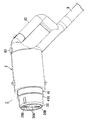
- the connector 1 includes a connector main body (housing) 2 and a cable 9 as shown in FIG.
- the cable 9 includes a pair of power lines 90, 91, a pair of CAN communication lines (not shown), a total of six transmission lines 92, 93, 94 (some transmission lines are not shown), It consists of an 11-core electric cable having a ground wire 95 (see FIG. 1).
- the cable 9 is provided with the connector main body 2 at one end side and is connected to the charge / discharge control device 200 at the other end side.
- the cable 9 is composed of a plurality of electric wires including the power lines 90 and 91 that are electrically connected to the inlet 103 (receiving connector) via the connecting portion 20, and is connected to the charge / discharge control device 200 (device). Connected.
- the connection portion 20 side as viewed from the connector body 2 is the “front” side
- the handle 42 side as viewed from the connector body 2 is the “rear” side.
- the connector main body 2 is formed in a cylindrical shape as a whole, the connecting portion 20 is provided at the front end, and the handle 42 is provided at the rear end.
- Connection unit 20 is detachably connected to inlet 103 (receiving side connector) of electric vehicle 100 (device equipped with a storage battery).
- the connecting portion 20 has four round holes 20A and 20B open on the front surface.
- a power contact (not shown) connected to the main circuit (electric circuit) 5 is accommodated in the space inside the two large-diameter round holes 20A.
- the space inside the two small-diameter round holes 20B is divided into four sections, and transmission and grounding contacts (not shown) are respectively stored in the sections.
- a cylindrical tube 41 is provided on the rear end side of the connecting portion 20 so as to be movable in the front-rear direction.
- the cylinder 41 is provided so that the connection part 20 is located inside thereof.
- the cylindrical body 41 is provided with an outer casing 410 at the front end thereof.
- the outer casing 410 is pushed forward by the elastic force of a spring (not shown) housed in the connector body 2.
- the connecting portion 20 is inserted into the inlet 103 and connected, the outer casing 410 is pushed onto one surface of the inlet 103, and the cylindrical body 41 moves rearward.
- the engaging claws pushed by the cylindrical body 41 and retracted into the connector main body 2 jump out of the connector main body 2 and engage with engaging grooves (not shown) of the inlet 103.
- the shape and structure of the cylinder 41 are not limited to this embodiment.
- the release button 43 provided on the connector body 2 When the release button 43 provided on the connector body 2 is operated (pressed), the engagement claw is retracted into the connector body 2 and the engagement with the engagement groove is released. Further, a switch (detection switch) that is turned off when the engaging claw is retracted into the connector main body 2 and turned on when the engaging claw is advanced out of the connector main body 2 in the connector main body 2. 24 (see FIG. 1) is stored. That is, the detection switch 24 is turned on when the connection unit 20 is normally connected to the inlet 103.
- a lock mechanism portion 23 for locking to the connector body 2 is provided in the connector main body 2 (see FIGS. 1 and 3).
- the lock mechanism unit 23 includes a solenoid 230 (solenoid actuator).
- the solenoid 230 includes a coil 231 (solenoid coil) and a plunger (not shown).
- the solenoid 230 when the detection switch 24 is on and charge / discharge is possible in the diagnosis before charge / discharge, the drive current supplied from the charge / discharge control device 200 via the transmission line 94 and the ground line 95 flows to the coil 231. To drive the plunger (see FIGS.
- the plunger restricts the movement of the engaging claw. That is, when the lock mechanism portion 23 is in the locked state, the engagement between the engagement claw and the engagement groove cannot be artificially released, and when the lock mechanism portion 23 is in the unlocked state, the release button 43 is pressed. Thus, the engagement between the engagement claw and the engagement groove can be artificially released.
- a main contact 21, an auxiliary contact 22, an overcurrent trip device 25, a short-circuit trip device 26, and an abnormal trip device 27 are accommodated in the connector body 2.
- a connector lock detection unit 28, an abnormal temperature detection unit 29, a temperature detection element 30, a contact state detection unit 31, a drive device 32, a voltage signal transmission / reception unit 33, a power supply filter 34 and the like are housed.
- the connector main body 2 (housing) is provided at the tip of the cable 9 and houses the connecting portion 20, the opening / closing portion, the abnormality detecting portion, and the voltage signal transmitting / receiving portion 33 (transmitting portion).
- the opening / closing section includes a main contact 21, a mechanical opening / closing mechanism, an abnormal trip device 27, and a drive device 32.
- the abnormality detection unit includes a connector lock detection unit 28 and an abnormal temperature detection unit 29.
- the main contact 21 is provided in the main circuit (electric circuit) 5 through which the charging current and discharging current of the in-vehicle battery 102 flow.
- the main contact 21 is closed when the connecting portion 20 is connected to the inlet 103, and the main contact 21 is opened when the connecting portion 20 is not connected to the inlet 103.
- a mechanical opening / closing mechanism (not shown) is provided. However, since such an opening / closing mechanism is well known in the technical field such as a circuit breaker, the illustration and description of the detailed configuration are omitted.
- the auxiliary contact 22 has a pair of switching contacts 220 and 221 and a common contact 222.
- the auxiliary contact 22 selectively switches the common contact 222 to one of the switching contacts 220 and 221 in conjunction with the main contact 21.
- the contact state detection unit 31 detects the state (open state and closed state) of the main contact 21 based on the switching state of the auxiliary contact 22, and outputs the detection result to the voltage signal transmission / reception unit 33.
- the overcurrent trip device 25 is configured to trip (open) the main contact 21 by an opening / closing mechanism when a predetermined overload current continues to flow to the main circuit (electric circuit) 5 for a predetermined time or longer.
- the short-circuit trip device 26 is configured to trip the main contact 21 by an opening / closing mechanism when a short-circuit current flows through the main circuit (electric circuit) 5.
- the abnormal trip device 27 is configured to trip the main contact 21 by an opening / closing mechanism when driven by the drive device 32.
- the overcurrent tripping device 25, the short-circuit tripping device 26, the tripping device 27 at the time of abnormality, and the driving device 32 can all be realized by using a conventionally known technique in the technical field such as a circuit breaker. The illustration and description of the various configurations are omitted.
- the main contact 21, the opening / closing mechanism, the abnormal trip device 27, and the drive device 32 constitute an opening / closing section.
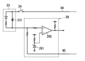
- the connector lock detection unit 28 uses a comparator 280 to determine the magnitude of the current (drive current) flowing through the coil 231 of the lock mechanism 23 and the magnitude of the reference current (the zener current of the zener diode 281). Compare. When the lock mechanism unit 23 is in an unlocked state or when an abnormality such as a disconnection occurs and a drive current does not flow (lock abnormality state), the output of the comparator 280 becomes a high level. On the other hand, when the lock mechanism unit 23 is in a locked state and a normal state (a state in which a drive current flows through the solenoid 230), the output of the comparator 280 is at a low level. The detection result of the connector lock detector 28 (output of the comparator 280) is output to the voltage signal transmitter / receiver 33.
- the abnormal temperature detection unit 29 detects the temperature of the connection unit 20 with a temperature detection element 30 provided in the vicinity of the connection unit 20, and when the detected temperature exceeds a predetermined upper limit value, the abnormal temperature detection result is transmitted to the voltage signal transmission / reception unit 33. Output to.
- the temperature detection element 30 is composed of, for example, a thermistor.
- the connector lock detection unit 28 and the abnormal temperature detection unit 29 correspond to an abnormality detection unit that detects an abnormality of the connection unit 20.
- the voltage signal transmission / reception unit 33 adjusts the line voltage between the transmission line 93 and the ground line 95, thereby charging / discharging the detection results of the connector lock detection unit 28, the abnormal temperature detection unit 29, and the contact state detection unit 31. Transmit to device 200. That is, in the connector 1 of the present embodiment, the voltage signal transmission / reception unit 33 detects an abnormality in the charge / discharge control device 200 (device) via at least one first wire (transmission line 93) of the plurality of wires. This corresponds to a transmission unit that transmits the detection result of the unit.
- the voltage signal transmission / reception unit 33 receives a control signal transmitted as a voltage signal from the charge / discharge control device 200, controls the drive device 32 based on the control signal, and drives the trip device 27 at the time of abnormality.
- the main contact 21 is pulled off (opened).
- the power supply filter 34 filters a noise component from a voltage (for example, a DC voltage of 12 volts) supplied from the charge / discharge control device 200 via the transmission line 92, and detects each of the detection units 28, 29, 31 and the drive device 32, The voltage signal transmitting / receiving unit 33 is supplied.
- a voltage for example, a DC voltage of 12 volts
- the power supply filter 34 is not essential and may be omitted.
- the charging / discharging control device 200 supplies power to the connector 1 and the electric vehicle 100 by applying a specified voltage (12 V DC voltage; the same applies hereinafter) between the transmission line 92 and the ground line 95.
- the electronic control unit of the electric vehicle 100 recognizes the start of the charging flow by applying the specified voltage, and transmits parameters such as the maximum voltage and the battery capacity of the in-vehicle battery 102 to the charge / discharge control device 200 by CAN communication. .
- the charging / discharging control device 200 When the charging / discharging control device 200 receives a parameter from the electronic control unit of the electric vehicle 100, the charge / discharge control device 200 confirms that the electric vehicle 100 is a chargeable electric vehicle. Thereafter, the charge / discharge control device 200 transmits information such as the maximum output voltage and the maximum output current of the charge / discharge control device 200 to the electronic control unit of the electric vehicle 100 by CAN communication.
- the electronic control unit of the electric vehicle 100 confirms the compatibility between the electric vehicle 100 and the charge / discharge control device 200 based on the information received from the charge / discharge control device 200, and permits permission to start charging if there is no problem with the compatibility.
- the signal is transmitted to the charge / discharge control apparatus 200 via the transmission line.
- the charge / discharge control device 200 Upon receiving the permission signal, the charge / discharge control device 200 applies a specified voltage between the transmission line 94 and the ground line 95 to cause a drive current to flow through the lock mechanism 23 of the connector 1 and lock the lock mechanism 23. State. Thereafter, the charge / discharge control apparatus 200 notifies the electronic control unit of the electric vehicle 100 that the preparation for charging is complete via the transmission line.
- the electronic control unit of the electric vehicle 100 When receiving the notification from the charge / discharge control device 200, the electronic control unit of the electric vehicle 100 closes the contactor 101 and starts charging the in-vehicle battery 102. And if the capacity
- the charge / discharge control device 200 When the charge / discharge control device 200 receives the charge stop request, the charge / discharge control device 200 stops the current output.
- the electronic control unit of the electric vehicle 100 confirms that the current of the main circuit (electric circuit) 5 has decreased to a predetermined value or less, and then opens the contactor 101 and terminates charging via the transmission line. 200 is notified.
- the charging / discharging control device 200 stops applying the specified voltage between the transmission line 92 and the ground line 95 when receiving the notification of the end of charging. Furthermore, the charge / discharge control apparatus 200 stops applying the specified voltage between the transmission line 94 and the ground line 95 to place the lock mechanism unit 23 in an unlocked state, and ends the charging flow.
- the discharge flow starts.
- the charge / discharge control device 200 applies a specified voltage between the transmission line 92 and the ground line 95 to supply power to the connector 1 and the electric vehicle 100, and further transmits a discharge flow start request by CAN communication.
- the electronic control unit of the electric vehicle 100 transmits parameters such as the maximum voltage and battery capacity of the in-vehicle battery 102 to the charge / discharge control device 200 by CAN communication.
- the charge / discharge control device 200 When the charge / discharge control device 200 receives a parameter from the electronic control unit, it applies a specified voltage between the transmission line 94 and the ground line 95 to cause a drive current to flow through the lock mechanism unit 23 of the connector 1. Is locked. Thereafter, the charging / discharging control device 200 notifies the electronic control unit of the electric vehicle 100 that the preparation for discharging is completed via the transmission line.
- the electronic control unit of the electric vehicle 100 When receiving the notification from the charge / discharge control device 200, the electronic control unit of the electric vehicle 100 closes the contactor 101 and starts discharging the in-vehicle battery 102. When the capacity of the in-vehicle battery 102 reaches a predetermined lower limit value, the electronic control unit of the electric vehicle 100 transmits a discharge stop request through CAN communication.
- the charge / discharge control device 200 stops the inverter and stops the power supply to the load.
- the electronic control unit of the electric vehicle 100 confirms that the current of the main circuit (electric circuit) 5 has decreased to a predetermined value or less, and then opens the contactor 101 and terminates the discharge via the transmission line. 200 is notified.
- the charge / discharge control device 200 receives a notification of the end of discharge, the charge / discharge control device 200 stops applying the specified voltage between the transmission line 92 and the ground line 95. Furthermore, the charge / discharge control apparatus 200 stops applying the specified voltage between the transmission line 94 and the ground line 95 to place the lock mechanism unit 23 in an unlocked state, and ends the discharge flow.
- the abnormal temperature detection unit 29 displays the abnormal temperature detection result as a voltage.
- the signal is output to the signal transmitter / receiver 33.
- the voltage signal transmission / reception unit 33 receives the abnormal temperature detection result from the abnormal temperature detection unit 29, the voltage signal transmission / reception unit 33 transmits an abnormality notification signal to the charge / discharge control device 200.
- the abnormality notification signal is transmitted as a voltage signal by the voltage signal transmitting / receiving unit 33 adjusting the line voltage (signal voltage level) between the transmission line 93 and the ground line 95 to a predetermined value.
- the connector lock detection unit 28 causes an electrical abnormality of the lock mechanism unit 23. Assume that (lock abnormal state) is detected.
- the voltage signal transmission / reception unit 33 transmits an abnormality notification signal that notifies the electrical abnormality of the lock mechanism unit 23 to the charge / discharge control device 200.
- the abnormality notification signal is transmitted as a voltage signal by the voltage signal transmitting / receiving unit 33 adjusting the line voltage (signal voltage level) between the transmission line 93 and the ground line 95 to a predetermined value.
- the charge / discharge control device 200 when the charge / discharge control device 200 receives the abnormality notification signal from the connector 1, it transmits a control signal to the voltage signal transmitting / receiving unit 33.
- the voltage signal transmission / reception unit 33 receives the control signal, the voltage signal transmission / reception unit 33 controls the driving device 32 to drive the tripping device 27 at the time of abnormality to disconnect (open) the main contact 21.
- the open / close unit is configured to open and close the main circuit (electric circuit) 5 by the control signal transmitted from the charge / discharge control device 200 via the first electric wire (transmission line 93).
- Main contact 21, opening / closing mechanism, tripping device 27 in case of abnormality, driving device 32 are configured. Therefore, when discharging from the on-board battery 102 of the electric vehicle 100 to the outside of the vehicle, the electric circuit 5 is interrupted in the connector 1 connected to the inlet 103 of the electric vehicle 100, thereby improving safety when an abnormality occurs. Can be planned.
- the charge / discharge control device 200 performs a common measure of forcibly opening the main contact 21 with respect to the temperature abnormality of the connection part 20 and the electric abnormality of the lock mechanism part 23. Therefore, the voltage signal transmitting / receiving unit 33 of the connector 1 combines the abnormality notification signal that notifies the electrical abnormality of the lock mechanism unit 23 and the abnormality notification signal that notifies the temperature abnormality of the connection unit 20 into one, that is, the signal voltage. It is preferable to transmit with the same level.
- the abnormality detection unit is preferably configured to individually detect a plurality of types of abnormality (temperature abnormality of the connection unit 20, electrical abnormality of the lock mechanism unit 23, etc.).
- the voltage signal transmission / reception part 33 (transmission part) is comprised so that at least any two or more types of detection results may be collected into one and transmitted to the charging / discharging control apparatus 200 (apparatus) among multiple types of abnormality. Preferably it is done.
- the abnormality detection unit and the opening / closing unit are connected via at least one second electric wire (the transmission line 92 and the grounding wire 95) among the plurality of electric wires.
- the electric power supplied from the charge / discharge control device 200 is configured to operate.
- the abnormality detection unit and the opening / closing unit may be configured to operate with electric power supplied from the main circuit (electric circuit) 5.
- the abnormality detection unit and the opening / closing unit are supplied with power from the in-vehicle battery 102 or the power system, so that the main circuit (electric circuit) 5 can be shut off even when a high voltage is applied. Improvement can be achieved.
- the abnormality detection unit and the opening / closing unit can be operated even when power is not supplied from the in-vehicle battery 102 in the discharge flow. Therefore, the main circuit (electric circuit) 5 can be shut off before energization. Can improve safety. Whether or not to adopt the former configuration is arbitrary. Whether or not to adopt the latter configuration is also arbitrary.
- the electrical connection connector 1 of the present embodiment has the following first feature.
- the connector 1 for electrical connection includes a connection portion 20, a cable 9, and an opening / closing portion (main contact 21, mechanical opening / closing mechanism, tripping device 27 in case of abnormality, and driving device 32).
- the electrical connection connector 1 of the present embodiment includes an abnormality detection unit (connector lock detection unit 28, abnormal temperature detection unit 29), a voltage signal transmission / reception unit 33 (transmission unit), and a connector body 2 (housing). Is provided.
- the connection unit 20 is detachably connected to an inlet 103 (receiving side connector) of an electric vehicle 100 (device) on which an in-vehicle battery 102 (storage battery) is mounted.
- the cable 9 is composed of a plurality of electric wires including power supply lines 90 and 91 that are electrically connected to the inlet 103 via the connection portion 20.
- the cable 9 is connected to a charge / discharge control device 200 (device) that performs at least one of power feeding to the electric vehicle 100 and power reception from the electric vehicle 100.
- the open / close unit opens and closes the main circuit (electric circuit) 5 that connects the connection unit 20 and the power supply lines 90 and 91.
- the abnormality detection unit detects an abnormality in the connection unit 20.
- the voltage signal transmission / reception unit 33 transmits information to the charge / discharge control device 200 via an electric wire.
- the connector main body 2 is provided at the tip of the cable 9 and houses the connection unit 20, the opening / closing unit, the abnormality detection unit, and the voltage signal transmission / reception unit 33.
- the open / close unit is configured to open and close the main circuit (electric circuit) 5 by a control signal transmitted via the electric wire.
- the electrical connection connector 1 of the present embodiment includes the connection portion 20, the cable 9, and the opening and closing portions (main contact 21, mechanical opening and closing mechanism, abnormal trip device 27, drive device 32).
- the electrical connection connector 1 of the present embodiment includes an abnormality detection unit (connector lock detection unit 28, abnormal temperature detection unit 29), a voltage signal transmission / reception unit 33 (transmission unit), and a connector body 2 (housing). Is provided.
- the connection unit 20 is detachably connected to an inlet 103 (receiving side connector) of an electric vehicle 100 (device) on which an in-vehicle battery 102 (storage battery) is mounted.
- the cable 9 is composed of a plurality of electric wires including power supply lines 90 and 91 that are electrically connected to the inlet 103 via the connection portion 20. Further, the cable 9 is connected to a charge / discharge control device 200 (device) that performs at least one of power feeding to the electric vehicle 100 and power reception from the electric vehicle 100.
- the open / close unit opens and closes the main circuit (electric circuit) 5 that connects the connection unit 20 and the power supply lines 90 and 91.
- the abnormality detection unit detects an abnormality in the connection unit 20.
- the voltage signal transmission / reception unit 33 transmits the detection result of the abnormality detection unit to the charge / discharge control device 200 via at least one first electric wire (transmission line 93) of the plurality of electric wires.
- the connector main body 2 is provided at the tip of the cable 9 and houses the connection unit 20, the opening / closing unit, the abnormality detection unit, and the voltage signal transmission / reception unit 33.
- the opening / closing unit is configured to open and close the main circuit (electric circuit) 5 by a control signal transmitted via the transmission line 93.
- the electrical connection connector 1 of the present embodiment may have the following second feature.
- the abnormality detection unit is configured to individually detect a plurality of types of abnormality (temperature abnormality of the connection unit 20, electrical abnormality of the lock mechanism unit 23, etc.).
- the voltage signal transmission / reception part 33 is comprised so that at least 2 or more types of detection results may be put together into one, and it may transmit to the charging / discharging control apparatus 200 among multiple types of abnormality.
- the electrical connection connector 1 of the present embodiment may have the following third feature in addition to the first or second feature.
- the abnormality detection unit and the opening / closing unit are configured to operate with electric power supplied from the charge / discharge control device 200 via an electric wire.
- the abnormality detection unit and the opening / closing unit are electric power supplied from the charge / discharge control device 200 via at least one second electric wire (the transmission line 92 and the grounding wire 95) of the plurality of electric wires. Configured to work.
- the electrical connection connector 1 of the present embodiment may have the following fourth feature in addition to the first or second feature.
- the abnormality detection unit and the opening / closing unit are configured to operate with electric power supplied via the power supply lines 90 and 91.
- the abnormality detection unit and the opening / closing unit are configured to operate with electric power supplied via the electric circuit 5.
- the present invention is configured so that the opening / closing part (main contact 21, mechanical opening / closing mechanism, tripping device 27 in case of abnormality, driving device 32) is connected via the first electric wire (transmission line 93).
- the main circuit (electric circuit) 5 is opened and closed by the transmitted control signal. Therefore, the present invention has an effect that safety can be improved when an abnormality occurs by cutting off the electric circuit 5 at a position close to the in-vehicle battery 102 (storage battery).
Abstract
This connector for an electrical connection (2) is provided with a connection part (20), a cable (9), switching units (21, 27, 32), abnormality detection units (28, 29), and a transmission unit (33). The connection part (20) is connected to a receiving-side connector (103) of equipment equipped with an accumulator (102). The cable (9) comprises a plurality of wires containing power wires, and is connected to a device (200) that supplies power to the equipment (100) and/or receives power from the equipment (100). The switching units (21, 27, 32) open and close electrical paths (5) connecting the connection part (20) and the power wires. The abnormality detection units (28, 29) detect abnormalities in the connection part. The transmission unit (33) transmits detection results of the abnormality detection units (28, 29) to the device (200) via at least one first wire among the plurality of wires. Moreover, the switching units (21, 27, 32) are configured in such a manner as to open and close the electrical paths by means of a control signal transmitted via the first wire.
Description
本発明は、電気接続用コネクタに関する。
The present invention relates to an electrical connection connector.
従来、蓄電池を有する機器と、当該機器に充電用の電力を供給する装置とを電気的に接続するために電気接続用コネクタが利用されている。このような電気接続用コネクタの従来例として、電気自動車の充電インレットに接続される充電コネクタを例示する(例えば、文献1(日本国特許出願公開番号2010-239827)参照)。
Conventionally, an electrical connection connector is used to electrically connect a device having a storage battery and a device that supplies power for charging to the device. As a conventional example of such a connector for electrical connection, a charging connector connected to a charging inlet of an electric vehicle is illustrated (for example, see Document 1 (Japanese Patent Application Publication No. 2010-239827)).
文献1には、充電コネクタ及び充電ケーブルを介して電気自動車の蓄電池(車載電池)を充電する充電器が開示されている。この充電器は、地絡及び漏電を検出する機能を有し、地絡又は漏電を検出したときに電気自動車への給電を停止するように構成されている。
Document 1 discloses a charger for charging a storage battery (vehicle battery) of an electric vehicle via a charging connector and a charging cable. This charger has a function of detecting a ground fault and a ground fault, and is configured to stop power feeding to the electric vehicle when a ground fault or a ground fault is detected.
近年、電気自動車の蓄電池から車外の負荷(例えば、住宅内の照明器具など)に給電することが行われている。この場合、コネクタとケーブルを介して電気自動車と充放電制御装置とが電気的に接続される。充放電制御装置は、交流電力と直流電力を双方向に電力変換して蓄電池の充電と蓄電池から車外の負荷への給電とを制御する。
In recent years, power is supplied from a storage battery of an electric vehicle to a load outside the vehicle (for example, a lighting device in a house). In this case, the electric vehicle and the charge / discharge control device are electrically connected via the connector and the cable. The charge / discharge control device bi-directionally converts AC power and DC power to control charging of the storage battery and power feeding from the storage battery to a load outside the vehicle.
文献1記載の従来例では、充電器から電気自動車の蓄電池を充電するのみであるから、地絡や漏電などの異常が発生したときに充電器内で給電を停止すれば十分である。
In the conventional example described in Document 1, since the storage battery of the electric vehicle is only charged from the charger, it is sufficient to stop the power supply in the charger when an abnormality such as a ground fault or electric leakage occurs.
しかしながら、電気自動車の蓄電池から車外に放電している場合、充放電制御装置が蓄電池からの給電路を遮断したとしても、コネクタが蓄電池と接続されている。このため、コネクタやケーブルの更なる安全性の向上が求められていた。
However, when discharging from the storage battery of the electric vehicle to the outside of the vehicle, the connector is connected to the storage battery even if the charge / discharge control device cuts off the power supply path from the storage battery. For this reason, the further safety | security improvement of the connector and the cable was calculated | required.
本発明は、上記課題に鑑みて為されており、異常発生時における安全性の向上を図ることを目的とする。
The present invention has been made in view of the above problems, and aims to improve safety when an abnormality occurs.
本発明に係る第1の形態の電気接続用コネクタは、接続部と、ケーブルと、開閉部と、異常検出部と、伝達部と、筐体とを備える。前記接続部は、蓄電池を搭載した機器の受け側コネクタと挿抜自在に接続される。前記ケーブルは、前記接続部を介して前記受け側コネクタに電気的に接続される電源線を含む複数の電線からなり、前記機器への給電及び前記機器からの受電の少なくとも一方を行う装置に接続される。前記開閉部は、前記接続部と前記電源線を繋ぐ電路を開閉する。前記異常検出部は、前記接続部の異常を検出する。前記伝達部は、前記複数の電線のうちの少なくとも1本の第1の電線を介して前記異常検出部の検出結果を前記装置に伝達する。前記筐体は、前記ケーブルの先端に設けられて前記接続部、前記開閉部、前記異常検出部、前記伝達部を収納する。そして、前記開閉部は、前記第1の電線を介して伝達される制御信号によって前記電路を開閉するように構成される。
The electrical connection connector according to the first aspect of the present invention includes a connection portion, a cable, an opening / closing portion, an abnormality detection portion, a transmission portion, and a housing. The connecting portion is detachably connected to a receiving connector of a device equipped with a storage battery. The cable is composed of a plurality of electric wires including a power line electrically connected to the receiving connector via the connecting portion, and is connected to a device that performs at least one of power feeding to the device and power receiving from the device. Is done. The opening / closing part opens and closes an electric circuit connecting the connection part and the power line. The abnormality detection unit detects an abnormality in the connection unit. The transmission unit transmits a detection result of the abnormality detection unit to the device via at least one first electric wire of the plurality of electric wires. The housing is provided at a tip of the cable and houses the connection portion, the opening / closing portion, the abnormality detection portion, and the transmission portion. And the said opening-and-closing part is comprised so that the said electric circuit may be opened and closed by the control signal transmitted via the said 1st electric wire.
本発明に係る第2の形態の電気接続用コネクタは、第1の形態に加えて、前記異常検出部は、複数種類の異常を個別に検出するように構成される。そして、前記伝達部は、前記複数種類の異常のうち、少なくとも2種類以上の検出結果を1つに纏めて、前記装置に伝達するように構成される。
In addition to the first embodiment, the electrical connection connector according to the second embodiment of the present invention is configured such that the abnormality detection unit individually detects a plurality of types of abnormality. And the said transmission part is comprised so that at least 2 or more types of detection results may be collected into one and transmitted to the said apparatus among the said multiple types of abnormality.
本発明に係る第3の形態の電気接続用コネクタは、第1の形態に加えて、前記異常検出部並びに前記開閉部は、前記複数の電線のうちの少なくとも1本の第2の電線を介して、前記装置から供給される電力で動作するように構成される。
According to a third aspect of the electrical connection connector of the present invention, in addition to the first form, the abnormality detection unit and the opening / closing unit are connected via at least one second electric wire of the plurality of electric wires. And configured to operate with electric power supplied from the apparatus.
本発明に係る第4の形態の電気接続用コネクタは、第1の形態に加えて、前記異常検出部並びに前記開閉部は、前記電路を介して供給される電力で動作するように構成される。
According to a fourth aspect of the electrical connection connector of the present invention, in addition to the first aspect, the abnormality detection unit and the opening / closing unit are configured to operate with electric power supplied through the electric circuit. .
以下、車載電池(蓄電池)を搭載した電気自動車(機器)のインレット(受け側コネクタ)と挿抜自在に接続され、車載電池の充電並びに車載電池から車両外の負荷への給電を行うためのコネクタに本発明の技術思想を適用した実施形態について説明する。ただし、蓄電池を搭載した機器は電気自動車に限定されず、例えば、太陽電池や燃料電池で生成される電力を蓄電する据え置き型の蓄電装置などであっても構わない。
In the following, it is connected to the inlet (receiving connector) of an electric vehicle (equipment) equipped with an in-vehicle battery (storage battery) so that it can be freely inserted and removed, and the connector for charging the in-vehicle battery and supplying power from the in-vehicle battery to a load outside the vehicle An embodiment to which the technical idea of the present invention is applied will be described. However, the device equipped with a storage battery is not limited to an electric vehicle, and may be a stationary power storage device that stores power generated by a solar cell or a fuel cell, for example.
図1は、本実施形態の電気接続用コネクタ1(以下、「コネクタ」と略す。)を含む充放電システムA1のシステム構成図である。この充放電システムA1は、車載電池102(蓄電池)を搭載した電気自動車100と、充放電制御装置200と、コネクタ1とで構成される。
FIG. 1 is a system configuration diagram of a charge / discharge system A1 including an electrical connection connector 1 (hereinafter abbreviated as “connector”) of the present embodiment. This charging / discharging system A1 is comprised by the electric vehicle 100 carrying the vehicle-mounted battery 102 (storage battery), the charging / discharging control apparatus 200, and the connector 1. FIG.
充放電制御装置200(装置)は、電気自動車100(機器)への給電及び電気自動車100からの受電を行うように構成されている。なお、充放電制御装置200(装置)は、電気自動車100(機器)への給電のみを行うように構成されていてもよいし、電気自動車100からの受電のみを行うように構成されていてもよい。充放電制御装置200は、商用の電力系統から供給される交流電圧・電流を直流電圧・電流に変換するコンバータ(図示せず)を備える。また、充放電制御装置200は、車載電池102から供給される直流電圧・電流を交流電圧・電流に変換するインバータ(図示せず)などを備える。さらに、充放電制御装置200は、電気自動車100からの指示に基づいてコンバータやインバータの出力を調整する機能や、地絡や漏電などの異常を検出してコンバータ及びインバータを停止させる機能などを有している。
The charge / discharge control device 200 (device) is configured to supply power to the electric vehicle 100 (device) and to receive power from the electric vehicle 100. The charge / discharge control device 200 (device) may be configured to supply power only to the electric vehicle 100 (device), or may be configured to receive power only from the electric vehicle 100. Good. The charge / discharge control device 200 includes a converter (not shown) that converts an AC voltage / current supplied from a commercial power system into a DC voltage / current. The charge / discharge control apparatus 200 includes an inverter (not shown) that converts a DC voltage / current supplied from the in-vehicle battery 102 into an AC voltage / current. Furthermore, the charge / discharge control device 200 has a function of adjusting the output of the converter and the inverter based on an instruction from the electric vehicle 100, a function of detecting an abnormality such as a ground fault and an electric leakage, and a function of stopping the converter and the inverter. is doing.
電気自動車100は、推進動力用の車載電池102の他に、充放電制御装置200と通信する電子制御ユニット(Electronic Control Unit:ECU、図示せず)などのための補助電池(図示せず)を搭載している。ここで、電気自動車100に設けられたインレット103(受け側コネクタ)は、日本規格協会から発行されている標準仕様書(TS D 0007:電気自動車用急速充電の基本機能)に規定されたインタフェースを有している。このインレット103は、車載電池102の陽極及び陰極と接続される一対の電源用電極と、CAN(Controller Area Network)通信用の一対の通信用電極と、アナログ信号伝送用の4つの信号用電極と、接地用の接地電極とを有している。なお、一対の電源用電極と車載電池102の陽極及び陰極との間に、それぞれコンタクタ(Contactor:電磁接触器)101が挿入されている。これらのコンタクタ101は、電気自動車100の電子制御ユニットによって開閉制御される。
In addition to the in-vehicle battery 102 for propulsion power, the electric vehicle 100 includes an auxiliary battery (not shown) for an electronic control unit (ECU, not shown) that communicates with the charge / discharge control device 200. It is installed. Here, the inlet 103 (receiving connector) provided in the electric vehicle 100 has an interface defined in a standard specification (TS D 0007: basic function of quick charging for electric vehicles) issued by the Japanese Standards Association. Have. The inlet 103 includes a pair of power electrodes connected to the anode and cathode of the in-vehicle battery 102, a pair of communication electrodes for CAN (Controller (Area Network) communication, and four signal electrodes for analog signal transmission. And a ground electrode for grounding. A contactor (electromagnetic contactor) 101 is inserted between the pair of power supply electrodes and the anode and cathode of the in-vehicle battery 102. These contactors 101 are controlled to be opened and closed by an electronic control unit of the electric vehicle 100.
コネクタ1は、図2に示すようにコネクタ本体(筐体)2とケーブル9とで構成される。ケーブル9は、一対の電源線90,91と、一対のCAN通信線(図示せず)と、合計6本の伝送線92,93,94(一部の伝送線は、図示を省略)と、接地線95とを有する11心の電気ケーブルからなる(図1参照)。ケーブル9は、一端側にコネクタ本体2が設けられ、他端側が充放電制御装置200に接続されている。換言すれば、ケーブル9は、接続部20を介してインレット103(受け側コネクタ)に電気的に接続される電源線90,91を含む複数の電線からなり、充放電制御装置200(装置)に接続される。なお、以下の説明では、図2におけるコネクタ本体2の中心軸方向において、コネクタ本体2から見て接続部20側を「前」側、コネクタ本体2から見てハンドル42側を「後」側と定義する。
The connector 1 includes a connector main body (housing) 2 and a cable 9 as shown in FIG. The cable 9 includes a pair of power lines 90, 91, a pair of CAN communication lines (not shown), a total of six transmission lines 92, 93, 94 (some transmission lines are not shown), It consists of an 11-core electric cable having a ground wire 95 (see FIG. 1). The cable 9 is provided with the connector main body 2 at one end side and is connected to the charge / discharge control device 200 at the other end side. In other words, the cable 9 is composed of a plurality of electric wires including the power lines 90 and 91 that are electrically connected to the inlet 103 (receiving connector) via the connecting portion 20, and is connected to the charge / discharge control device 200 (device). Connected. In the following description, in the central axis direction of the connector body 2 in FIG. 2, the connection portion 20 side as viewed from the connector body 2 is the “front” side, and the handle 42 side as viewed from the connector body 2 is the “rear” side. Define.
コネクタ本体2は、全体として円筒形に形成され、前端に接続部20が設けられ、後端にハンドル42が設けられている。接続部20は、電気自動車100(蓄電池を搭載した機器)のインレット103(受け側コネクタ)と挿抜自在に接続される。接続部20は、前面に4つの丸孔20A,20Bが開口している。大径の2つの丸孔20Aの内側の空間には主回路(電路)5に接続された電源用コンタクト(図示せず)がそれぞれ収納されている。一方、小径の2つの丸孔20Bの内側の空間は、4つの区画に分けられており、各区画に伝送用及び接地用のコンタクト(図示せず)がそれぞれ収納されている。
The connector main body 2 is formed in a cylindrical shape as a whole, the connecting portion 20 is provided at the front end, and the handle 42 is provided at the rear end. Connection unit 20 is detachably connected to inlet 103 (receiving side connector) of electric vehicle 100 (device equipped with a storage battery). The connecting portion 20 has four round holes 20A and 20B open on the front surface. A power contact (not shown) connected to the main circuit (electric circuit) 5 is accommodated in the space inside the two large-diameter round holes 20A. On the other hand, the space inside the two small-diameter round holes 20B is divided into four sections, and transmission and grounding contacts (not shown) are respectively stored in the sections.
接続部20の後端側には、円筒形の筒体41が前後方向に移動自在に設けられている。筒体41は、その内側に接続部20が位置するように設けられている。筒体41には、その前端に外鍔410が設けられている。外鍔410は、コネクタ本体2内に収納されているばね(図示せず)の弾性力によって前向きに押されている。接続部20をインレット103に挿入して接続すると、インレット103の一面に外鍔410が押されて筒体41が後方に移動する。そして、筒体41に押されてコネクタ本体2内に退避していた係合爪が、コネクタ本体2外に飛び出してインレット103の係合溝(図示せず)に係合する。ただし、筒体41の形状及び構造は本実施形態に限定されない。係合爪は、コネクタ本体2に設けられた解除釦43が操作される(押される)と、コネクタ本体2内に退避して係合溝との係合が解除される。また、コネクタ本体2内には、係合爪がコネクタ本体2内に退避しているときにオフとなり、係合爪がコネクタ本体2外に進出しているときにオンとなるスイッチ(検出スイッチ)24(図1参照)が収納されている。すなわち、検出スイッチ24は、接続部20がインレット103に正常に接続されたときにオンする。
A cylindrical tube 41 is provided on the rear end side of the connecting portion 20 so as to be movable in the front-rear direction. The cylinder 41 is provided so that the connection part 20 is located inside thereof. The cylindrical body 41 is provided with an outer casing 410 at the front end thereof. The outer casing 410 is pushed forward by the elastic force of a spring (not shown) housed in the connector body 2. When the connecting portion 20 is inserted into the inlet 103 and connected, the outer casing 410 is pushed onto one surface of the inlet 103, and the cylindrical body 41 moves rearward. Then, the engaging claws pushed by the cylindrical body 41 and retracted into the connector main body 2 jump out of the connector main body 2 and engage with engaging grooves (not shown) of the inlet 103. However, the shape and structure of the cylinder 41 are not limited to this embodiment. When the release button 43 provided on the connector body 2 is operated (pressed), the engagement claw is retracted into the connector body 2 and the engagement with the engagement groove is released. Further, a switch (detection switch) that is turned off when the engaging claw is retracted into the connector main body 2 and turned on when the engaging claw is advanced out of the connector main body 2 in the connector main body 2. 24 (see FIG. 1) is stored. That is, the detection switch 24 is turned on when the connection unit 20 is normally connected to the inlet 103.
ここで、充電中に解除釦43が操作されて(押されて)係合爪と係合溝の係合が解除されることを防止するため、係合爪がコネクタ本体2内に退避しないようにロックするロック機構部23がコネクタ本体2内に設けられている(図1、図3参照)。ロック機構部23は、ソレノイド230(ソレノイドアクチュエータ)を有している。ソレノイド230は、コイル231(ソレノイドコイル)と、プランジャ(図示せず)とを備える。ソレノイド230は、検出スイッチ24がオン且つ充放電前の診断で充放電可のときに、充放電制御装置200から伝送線94と接地線95を介して供給される駆動電流がコイル231に流れることでプランジャを駆動する(図1、図3参照)。そして、プランジャは、係合爪の動きを規制する。つまり、ロック機構部23がロック状態のときは係合爪と係合溝の係合を人為的に解除することができず、ロック機構部23が非ロック状態のときに解除釦43の押操作で係合爪と係合溝の係合を人為的に解除することができる。
Here, in order to prevent the release button 43 from being operated (pressed) during charging to release the engagement between the engagement claw and the engagement groove, the engagement claw is not retracted into the connector body 2. A lock mechanism portion 23 for locking to the connector body 2 is provided in the connector main body 2 (see FIGS. 1 and 3). The lock mechanism unit 23 includes a solenoid 230 (solenoid actuator). The solenoid 230 includes a coil 231 (solenoid coil) and a plunger (not shown). In the solenoid 230, when the detection switch 24 is on and charge / discharge is possible in the diagnosis before charge / discharge, the drive current supplied from the charge / discharge control device 200 via the transmission line 94 and the ground line 95 flows to the coil 231. To drive the plunger (see FIGS. 1 and 3). The plunger restricts the movement of the engaging claw. That is, when the lock mechanism portion 23 is in the locked state, the engagement between the engagement claw and the engagement groove cannot be artificially released, and when the lock mechanism portion 23 is in the unlocked state, the release button 43 is pressed. Thus, the engagement between the engagement claw and the engagement groove can be artificially released.
コネクタ本体2内には、図1に示すように、主接点21、補助接点22、過電流引き外し装置25、短絡引き外し装置26、異常時引き外し装置27が収納されている。また、コネクタ本体2内には、その他、コネクタロック検出部28、異常温度検出部29、温度検出素子30、接点状態検出部31、駆動装置32、電圧信号送受信部33、電源フィルタ34などが収納されている。換言すれば、コネクタ本体2(筐体)は、ケーブル9の先端に設けられて、接続部20、開閉部、異常検出部、電圧信号送受信部33(伝達部)を収納する。なお、後述するが、開閉部は、主接点21と、機械式の開閉機構と、異常時引き外し装置27と、駆動装置32とで構成されている。また、後述するが、異常検出部は、コネクタロック検出部28と、異常温度検出部29とで構成されている。
As shown in FIG. 1, a main contact 21, an auxiliary contact 22, an overcurrent trip device 25, a short-circuit trip device 26, and an abnormal trip device 27 are accommodated in the connector body 2. In addition, in the connector main body 2, a connector lock detection unit 28, an abnormal temperature detection unit 29, a temperature detection element 30, a contact state detection unit 31, a drive device 32, a voltage signal transmission / reception unit 33, a power supply filter 34 and the like are housed. Has been. In other words, the connector main body 2 (housing) is provided at the tip of the cable 9 and houses the connecting portion 20, the opening / closing portion, the abnormality detecting portion, and the voltage signal transmitting / receiving portion 33 (transmitting portion). As will be described later, the opening / closing section includes a main contact 21, a mechanical opening / closing mechanism, an abnormal trip device 27, and a drive device 32. As will be described later, the abnormality detection unit includes a connector lock detection unit 28 and an abnormal temperature detection unit 29.
主接点21は、車載電池102の充電電流や放電電流が流れる主回路(電路)5に設けられている。なお、コネクタ本体2内には、接続部20がインレット103に接続されているときに主接点21を閉極し、接続部20がインレット103に接続されていないときに主接点21を開極する機械式の開閉機構(図示せず)が設けられている。ただし、このような開閉機構は、回路遮断器などの技術分野では周知であるから、詳細な構成の図示並びに説明は省略する。
The main contact 21 is provided in the main circuit (electric circuit) 5 through which the charging current and discharging current of the in-vehicle battery 102 flow. In the connector body 2, the main contact 21 is closed when the connecting portion 20 is connected to the inlet 103, and the main contact 21 is opened when the connecting portion 20 is not connected to the inlet 103. A mechanical opening / closing mechanism (not shown) is provided. However, since such an opening / closing mechanism is well known in the technical field such as a circuit breaker, the illustration and description of the detailed configuration are omitted.
補助接点22は、一対の切替接点220,221と、共通接点222とを有する。補助接点22は、主接点21に連動して共通接点222を切替接点220,221の何れかに択一的に切り替える。接点状態検出部31は、補助接点22の切替状態に基づいて主接点21の状態(開状態と閉状態)を検出し、その検出結果を電圧信号送受信部33に出力する。
The auxiliary contact 22 has a pair of switching contacts 220 and 221 and a common contact 222. The auxiliary contact 22 selectively switches the common contact 222 to one of the switching contacts 220 and 221 in conjunction with the main contact 21. The contact state detection unit 31 detects the state (open state and closed state) of the main contact 21 based on the switching state of the auxiliary contact 22, and outputs the detection result to the voltage signal transmission / reception unit 33.
過電流引き外し装置25は、所定の過負荷電流が所定時間以上継続して主回路(電路)5に流れたときに開閉機構により主接点21を引き外す(開極する)ように構成される。また、短絡引き外し装置26は、主回路(電路)5に短絡電流が流れたときに開閉機構により主接点21を引き外すように構成される。さらに、異常時引き外し装置27は、駆動装置32によって駆動されたときに開閉機構により主接点21を引き外すように構成される。ただし、過電流引き外し装置25、短絡引き外し装置26、異常時引き外し装置27、駆動装置32は何れも回路遮断器などの技術分野で従来周知の技術を用いて実現可能であるから、詳細な構成についての図示並びに説明を省略する。本実施形態のコネクタ1では、主接点21と、開閉機構と、異常時引き外し装置27と、駆動装置32とで開閉部を構成している。
The overcurrent trip device 25 is configured to trip (open) the main contact 21 by an opening / closing mechanism when a predetermined overload current continues to flow to the main circuit (electric circuit) 5 for a predetermined time or longer. . The short-circuit trip device 26 is configured to trip the main contact 21 by an opening / closing mechanism when a short-circuit current flows through the main circuit (electric circuit) 5. Further, the abnormal trip device 27 is configured to trip the main contact 21 by an opening / closing mechanism when driven by the drive device 32. However, the overcurrent tripping device 25, the short-circuit tripping device 26, the tripping device 27 at the time of abnormality, and the driving device 32 can all be realized by using a conventionally known technique in the technical field such as a circuit breaker. The illustration and description of the various configurations are omitted. In the connector 1 of this embodiment, the main contact 21, the opening / closing mechanism, the abnormal trip device 27, and the drive device 32 constitute an opening / closing section.
コネクタロック検出部28は、例えば図3に示すように、ロック機構部23のコイル231に流れる電流(駆動電流)の大きさと、基準電流(ツェナーダイオード281のツェナー電流)の大きさとをコンパレータ280で比較する。ロック機構部23が非ロック状態のとき、または断線等の異常が生じて駆動電流が流れていない状態(ロック異常状態)のとき、コンパレータ280の出力がハイレベルとなる。一方、ロック機構部23がロック状態及び正常状態(ソレノイド230に駆動電流が流れている状態)のときは、コンパレータ280の出力がローレベルとなる。なお、コネクタロック検出部28の検出結果(コンパレータ280の出力)は電圧信号送受信部33に出力される。
For example, as shown in FIG. 3, the connector lock detection unit 28 uses a comparator 280 to determine the magnitude of the current (drive current) flowing through the coil 231 of the lock mechanism 23 and the magnitude of the reference current (the zener current of the zener diode 281). Compare. When the lock mechanism unit 23 is in an unlocked state or when an abnormality such as a disconnection occurs and a drive current does not flow (lock abnormality state), the output of the comparator 280 becomes a high level. On the other hand, when the lock mechanism unit 23 is in a locked state and a normal state (a state in which a drive current flows through the solenoid 230), the output of the comparator 280 is at a low level. The detection result of the connector lock detector 28 (output of the comparator 280) is output to the voltage signal transmitter / receiver 33.
異常温度検出部29は、接続部20の近傍に設けられる温度検出素子30で接続部20の温度を検出し、検出温度が所定の上限値を超えたら、異常温度検出結果を電圧信号送受信部33に出力する。温度検出素子30は、例えばサーミスタなどで構成される。本実施形態のコネクタ1では、コネクタロック検出部28と、異常温度検出部29とが、接続部20の異常を検出する異常検出部に相当する。
The abnormal temperature detection unit 29 detects the temperature of the connection unit 20 with a temperature detection element 30 provided in the vicinity of the connection unit 20, and when the detected temperature exceeds a predetermined upper limit value, the abnormal temperature detection result is transmitted to the voltage signal transmission / reception unit 33. Output to. The temperature detection element 30 is composed of, for example, a thermistor. In the connector 1 of the present embodiment, the connector lock detection unit 28 and the abnormal temperature detection unit 29 correspond to an abnormality detection unit that detects an abnormality of the connection unit 20.
電圧信号送受信部33は、伝送線93と接地線95との線間電圧を調整することにより、コネクタロック検出部28、異常温度検出部29、接点状態検出部31の各検出結果を充放電制御装置200へ伝送する。すなわち、本実施形態のコネクタ1では、電圧信号送受信部33が、複数の電線のうちの少なくとも1本の第1の電線(伝送線93)を介して充放電制御装置200(装置)に異常検出部の検出結果を伝達する伝達部に相当する。また、電圧信号送受信部33は、充放電制御装置200から電圧信号として伝送される制御信号を受信し、当該制御信号に基づいて駆動装置32を制御し、異常時引き外し装置27を駆動させて主接点21を引き外す(開極する)。
The voltage signal transmission / reception unit 33 adjusts the line voltage between the transmission line 93 and the ground line 95, thereby charging / discharging the detection results of the connector lock detection unit 28, the abnormal temperature detection unit 29, and the contact state detection unit 31. Transmit to device 200. That is, in the connector 1 of the present embodiment, the voltage signal transmission / reception unit 33 detects an abnormality in the charge / discharge control device 200 (device) via at least one first wire (transmission line 93) of the plurality of wires. This corresponds to a transmission unit that transmits the detection result of the unit. In addition, the voltage signal transmission / reception unit 33 receives a control signal transmitted as a voltage signal from the charge / discharge control device 200, controls the drive device 32 based on the control signal, and drives the trip device 27 at the time of abnormality. The main contact 21 is pulled off (opened).
電源フィルタ34は、伝送線92を介して充放電制御装置200から供給される電圧(例えば、12ボルトの直流電圧)からノイズ成分をフィルタリングし、各検出部28,29,31や駆動装置32、電圧信号送受信部33に供給している。ただし、電源フィルタ34は必須では無く、省略されても良い。
The power supply filter 34 filters a noise component from a voltage (for example, a DC voltage of 12 volts) supplied from the charge / discharge control device 200 via the transmission line 92, and detects each of the detection units 28, 29, 31 and the drive device 32, The voltage signal transmitting / receiving unit 33 is supplied. However, the power supply filter 34 is not essential and may be omitted.
次に、充放電システムA1の充電動作について説明する。
Next, the charging operation of the charge / discharge system A1 will be described.
コネクタ1がインレット103に接続された後、充放電制御装置200に対して充電開始操作が行われると充電フローが始まる。充放電制御装置200は、伝送線92と接地線95との間に規定電圧(12Vの直流電圧。以下、同じ。)を印加してコネクタ1並びに電気自動車100に給電する。電気自動車100の電子制御ユニットは、この規定電圧が印加されることで充電フローの開始を認識し、車載電池102の最大電圧や電池容量などのパラメータをCAN通信によって充放電制御装置200へ伝送する。
When the charging start operation is performed on the charge / discharge control device 200 after the connector 1 is connected to the inlet 103, the charging flow starts. The charging / discharging control device 200 supplies power to the connector 1 and the electric vehicle 100 by applying a specified voltage (12 V DC voltage; the same applies hereinafter) between the transmission line 92 and the ground line 95. The electronic control unit of the electric vehicle 100 recognizes the start of the charging flow by applying the specified voltage, and transmits parameters such as the maximum voltage and the battery capacity of the in-vehicle battery 102 to the charge / discharge control device 200 by CAN communication. .
充放電制御装置200は、電気自動車100の電子制御ユニットからパラメータを受け取ると、電気自動車100が充電可能な電気自動車であることを確認する。その後、充放電制御装置200は、充放電制御装置200の最大出力電圧、最大出力電流などの情報をCAN通信で電気自動車100の電子制御ユニットに伝送する。
When the charging / discharging control device 200 receives a parameter from the electronic control unit of the electric vehicle 100, the charge / discharge control device 200 confirms that the electric vehicle 100 is a chargeable electric vehicle. Thereafter, the charge / discharge control device 200 transmits information such as the maximum output voltage and the maximum output current of the charge / discharge control device 200 to the electronic control unit of the electric vehicle 100 by CAN communication.
電気自動車100の電子制御ユニットは、充放電制御装置200から受け取った情報により電気自動車100と充放電制御装置200との適合性を確認し、適合性に問題が無ければ、充電開始を許可する許可信号を伝送線を介して充放電制御装置200へ伝送する。
The electronic control unit of the electric vehicle 100 confirms the compatibility between the electric vehicle 100 and the charge / discharge control device 200 based on the information received from the charge / discharge control device 200, and permits permission to start charging if there is no problem with the compatibility. The signal is transmitted to the charge / discharge control apparatus 200 via the transmission line.
充放電制御装置200は、許可信号を受け取ると、伝送線94と接地線95との間に規定電圧を印加することでコネクタ1のロック機構部23に駆動電流を流し、ロック機構部23をロック状態とする。その後、充放電制御装置200は、充電準備が整ったことを伝送線を介して電気自動車100の電子制御ユニットに通知する。
Upon receiving the permission signal, the charge / discharge control device 200 applies a specified voltage between the transmission line 94 and the ground line 95 to cause a drive current to flow through the lock mechanism 23 of the connector 1 and lock the lock mechanism 23. State. Thereafter, the charge / discharge control apparatus 200 notifies the electronic control unit of the electric vehicle 100 that the preparation for charging is complete via the transmission line.
電気自動車100の電子制御ユニットは、充放電制御装置200から通知を受け取ると、コンタクタ101を閉極して車載電池102の充電を開始する。そして、車載電池102の容量が規定値に到達したら、電気自動車100の電子制御ユニットは、CAN通信によって充電停止要求を送信する。
When receiving the notification from the charge / discharge control device 200, the electronic control unit of the electric vehicle 100 closes the contactor 101 and starts charging the in-vehicle battery 102. And if the capacity | capacitance of the vehicle-mounted battery 102 reaches | attains a regulation value, the electronic control unit of the electric vehicle 100 will transmit a charge stop request | requirement by CAN communication.
充放電制御装置200は、充電停止要求を受け取ると電流出力を停止する。電気自動車100の電子制御ユニットは、主回路(電路)5の電流が所定値以下まで低下したことを確認した後、コンタクタ101を開極し、伝送線を介して充電の終了を充放電制御装置200に通知する。
When the charge / discharge control device 200 receives the charge stop request, the charge / discharge control device 200 stops the current output. The electronic control unit of the electric vehicle 100 confirms that the current of the main circuit (electric circuit) 5 has decreased to a predetermined value or less, and then opens the contactor 101 and terminates charging via the transmission line. 200 is notified.
充放電制御装置200は、充電終了の通知を受け取ると伝送線92と接地線95との間の規定電圧の印加を停止する。さらに、充放電制御装置200は、伝送線94と接地線95との間の規定電圧の印加を停止してロック機構部23を非ロック状態とし、充電フローを終了する。
The charging / discharging control device 200 stops applying the specified voltage between the transmission line 92 and the ground line 95 when receiving the notification of the end of charging. Furthermore, the charge / discharge control apparatus 200 stops applying the specified voltage between the transmission line 94 and the ground line 95 to place the lock mechanism unit 23 in an unlocked state, and ends the charging flow.
次に、充放電システムA1の放電動作について説明する。
Next, the discharge operation of the charge / discharge system A1 will be described.
コネクタ1がインレット103に接続された後、充放電制御装置200に対して放電開始操作が行われると放電フローが始まる。充放電制御装置200は、伝送線92と接地線95との間に規定電圧を印加してコネクタ1並びに電気自動車100に給電し、さらに、CAN通信によって放電フローの開始要求を伝送する。電気自動車100の電子制御ユニットは、放電フローの開始要求を受け取ると車載電池102の最大電圧や電池容量などのパラメータをCAN通信によって充放電制御装置200へ伝送する。
When the discharge start operation is performed on the charge / discharge control device 200 after the connector 1 is connected to the inlet 103, the discharge flow starts. The charge / discharge control device 200 applies a specified voltage between the transmission line 92 and the ground line 95 to supply power to the connector 1 and the electric vehicle 100, and further transmits a discharge flow start request by CAN communication. When receiving the discharge flow start request, the electronic control unit of the electric vehicle 100 transmits parameters such as the maximum voltage and battery capacity of the in-vehicle battery 102 to the charge / discharge control device 200 by CAN communication.
充放電制御装置200は、電子制御ユニットからパラメータを受け取ると伝送線94と接地線95との間に規定電圧を印加することでコネクタ1のロック機構部23に駆動電流を流し、ロック機構部23をロック状態とする。その後、充放電制御装置200は、放電準備が整ったことを伝送線を介して電気自動車100の電子制御ユニットに通知する。
When the charge / discharge control device 200 receives a parameter from the electronic control unit, it applies a specified voltage between the transmission line 94 and the ground line 95 to cause a drive current to flow through the lock mechanism unit 23 of the connector 1. Is locked. Thereafter, the charging / discharging control device 200 notifies the electronic control unit of the electric vehicle 100 that the preparation for discharging is completed via the transmission line.
電気自動車100の電子制御ユニットは、充放電制御装置200から通知を受け取ると、コンタクタ101を閉極して車載電池102の放電を開始する。なお、車載電池102の容量が所定の下限値に到達したら、電気自動車100の電子制御ユニットは、CAN通信によって放電停止要求を送信する。
When receiving the notification from the charge / discharge control device 200, the electronic control unit of the electric vehicle 100 closes the contactor 101 and starts discharging the in-vehicle battery 102. When the capacity of the in-vehicle battery 102 reaches a predetermined lower limit value, the electronic control unit of the electric vehicle 100 transmits a discharge stop request through CAN communication.
充放電制御装置200は、放電停止要求を受け取るとインバータを停止して負荷への給電を止める。電気自動車100の電子制御ユニットは、主回路(電路)5の電流が所定値以下まで低下したことを確認した後、コンタクタ101を開極し、伝送線を介して放電の終了を充放電制御装置200に通知する。充放電制御装置200は、放電終了の通知を受け取ると伝送線92と接地線95との間の規定電圧の印加を停止する。さらに、充放電制御装置200は、伝送線94と接地線95との間の規定電圧の印加を停止してロック機構部23を非ロック状態とし、放電フローを終了する。
When receiving the discharge stop request, the charge / discharge control device 200 stops the inverter and stops the power supply to the load. The electronic control unit of the electric vehicle 100 confirms that the current of the main circuit (electric circuit) 5 has decreased to a predetermined value or less, and then opens the contactor 101 and terminates the discharge via the transmission line. 200 is notified. When the charge / discharge control device 200 receives a notification of the end of discharge, the charge / discharge control device 200 stops applying the specified voltage between the transmission line 92 and the ground line 95. Furthermore, the charge / discharge control apparatus 200 stops applying the specified voltage between the transmission line 94 and the ground line 95 to place the lock mechanism unit 23 in an unlocked state, and ends the discharge flow.
ここで、上述した充電フロー又は放電フローにおいて、接続部20の温度が異常に上昇し、温度検出素子30の検出温度が上限値を超えた場合、異常温度検出部29が異常温度検出結果を電圧信号送受信部33に出力する。電圧信号送受信部33は、異常温度検出部29から異常温度検出結果を受け取ると異常通知信号を充放電制御装置200へ伝送する。この異常通知信号は、電圧信号送受信部33が伝送線93と接地線95との間の線間電圧(信号電圧レベル)を所定値に調整することで電圧信号として伝送される。
Here, in the above-described charging flow or discharging flow, when the temperature of the connection unit 20 rises abnormally and the detection temperature of the temperature detection element 30 exceeds the upper limit value, the abnormal temperature detection unit 29 displays the abnormal temperature detection result as a voltage. The signal is output to the signal transmitter / receiver 33. When the voltage signal transmission / reception unit 33 receives the abnormal temperature detection result from the abnormal temperature detection unit 29, the voltage signal transmission / reception unit 33 transmits an abnormality notification signal to the charge / discharge control device 200. The abnormality notification signal is transmitted as a voltage signal by the voltage signal transmitting / receiving unit 33 adjusting the line voltage (signal voltage level) between the transmission line 93 and the ground line 95 to a predetermined value.
また、充電フロー又は放電フローにおいて、充放電制御装置200が伝送線94と接地線95との間に規定電圧を印加しているときに、コネクタロック検出部28がロック機構部23の電気的異常(ロック異常状態)を検出したとする。電圧信号送受信部33は、電気的異常を検出したコネクタロック検出部28の出力がハイレベルになると、ロック機構部23の電気的異常を知らせる異常通知信号を充放電制御装置200へ伝送する。この異常通知信号は、電圧信号送受信部33が伝送線93と接地線95との間の線間電圧(信号電圧レベル)を所定値に調整することで電圧信号として伝送される。
In the charging flow or discharging flow, when the charging / discharging control device 200 applies a specified voltage between the transmission line 94 and the ground line 95, the connector lock detection unit 28 causes an electrical abnormality of the lock mechanism unit 23. Assume that (lock abnormal state) is detected. When the output of the connector lock detection unit 28 that has detected an electrical abnormality becomes high level, the voltage signal transmission / reception unit 33 transmits an abnormality notification signal that notifies the electrical abnormality of the lock mechanism unit 23 to the charge / discharge control device 200. The abnormality notification signal is transmitted as a voltage signal by the voltage signal transmitting / receiving unit 33 adjusting the line voltage (signal voltage level) between the transmission line 93 and the ground line 95 to a predetermined value.
一方、充放電制御装置200は、コネクタ1から異常通知信号を受け取ると電圧信号送受信部33へ制御信号を伝送する。電圧信号送受信部33は制御信号を受信すると駆動装置32を制御し、異常時引き外し装置27を駆動させて主接点21を引き外す(開極する)。これにより、接続部20の異常温度上昇による不具合が発生したり、ロック機構部23の異常によって充電中又は放電中にコネクタ1が誤ってインレットから外されたりするのを低減できる。
On the other hand, when the charge / discharge control device 200 receives the abnormality notification signal from the connector 1, it transmits a control signal to the voltage signal transmitting / receiving unit 33. When the voltage signal transmission / reception unit 33 receives the control signal, the voltage signal transmission / reception unit 33 controls the driving device 32 to drive the tripping device 27 at the time of abnormality to disconnect (open) the main contact 21. As a result, it is possible to reduce the occurrence of a problem due to an abnormal temperature rise of the connection part 20 or the accidental disconnection of the connector 1 from the inlet during charging or discharging due to an abnormality of the lock mechanism part 23.
上述のように本実施形態のコネクタ1では、充放電制御装置200から第1の電線(伝送線93)を介して伝達される制御信号によって主回路(電路)5を開閉するように、開閉部(主接点21、開閉機構、異常時引き外し装置27、駆動装置32)が構成されている。そのため、電気自動車100の車載電池102から車外に放電している場合、電気自動車100のインレット103に接続されているコネクタ1内で電路5を遮断することにより、異常発生時における安全性の向上を図ることができる。
As described above, in the connector 1 of the present embodiment, the open / close unit is configured to open and close the main circuit (electric circuit) 5 by the control signal transmitted from the charge / discharge control device 200 via the first electric wire (transmission line 93). (Main contact 21, opening / closing mechanism, tripping device 27 in case of abnormality, driving device 32) are configured. Therefore, when discharging from the on-board battery 102 of the electric vehicle 100 to the outside of the vehicle, the electric circuit 5 is interrupted in the connector 1 connected to the inlet 103 of the electric vehicle 100, thereby improving safety when an abnormality occurs. Can be planned.
ところで、接続部20の温度異常とロック機構部23の電気的異常に対して、充放電制御装置200は、主接点21を強制的に開極するという共通の対処を行う。したがって、コネクタ1の電圧信号送受信部33は、ロック機構部23の電気的異常を知らせる異常通知信号と、接続部20の温度異常を知らせる異常通知信号とを1つに纏めて、すなわち、信号電圧レベルを同じ値にして伝送することが好ましい。換言すれば、異常検出部は、複数種類の異常(接続部20の温度異常やロック機構部23の電気的異常など)を個別に検出するように構成されるのが好ましい。また、電圧信号送受信部33(伝達部)は、複数種類の異常のうち、少なくとも何れか2種類以上の検出結果を1つに纏めて、充放電制御装置200(装置)に伝達するように構成されるのが好ましい。
Incidentally, the charge / discharge control device 200 performs a common measure of forcibly opening the main contact 21 with respect to the temperature abnormality of the connection part 20 and the electric abnormality of the lock mechanism part 23. Therefore, the voltage signal transmitting / receiving unit 33 of the connector 1 combines the abnormality notification signal that notifies the electrical abnormality of the lock mechanism unit 23 and the abnormality notification signal that notifies the temperature abnormality of the connection unit 20 into one, that is, the signal voltage. It is preferable to transmit with the same level. In other words, the abnormality detection unit is preferably configured to individually detect a plurality of types of abnormality (temperature abnormality of the connection unit 20, electrical abnormality of the lock mechanism unit 23, etc.). Moreover, the voltage signal transmission / reception part 33 (transmission part) is comprised so that at least any two or more types of detection results may be collected into one and transmitted to the charging / discharging control apparatus 200 (apparatus) among multiple types of abnormality. Preferably it is done.
また、本実施形態のコネクタ1では、異常検出部並びに開閉部(ここでは、駆動装置32)が、複数の電線のうち少なくとも1本の第2の電線(伝送線92及び接地線95)を介して充放電制御装置200から供給される電力で動作するように構成されている。これに対して、異常検出部並びに開閉部は、主回路(電路)5から供給される電力で動作するように構成されても構わない。
In the connector 1 of the present embodiment, the abnormality detection unit and the opening / closing unit (here, the driving device 32) are connected via at least one second electric wire (the transmission line 92 and the grounding wire 95) among the plurality of electric wires. Thus, the electric power supplied from the charge / discharge control device 200 is configured to operate. On the other hand, the abnormality detection unit and the opening / closing unit may be configured to operate with electric power supplied from the main circuit (electric circuit) 5.
後者の構成では、異常検出部並びに開閉部が車載電池102や電力系統から電源供給を受けるので、高電圧が印加されているときでも主回路(電路)5を遮断することができて安全性の向上が図れる。一方、前者の構成では、例えば、放電フローにおいて車載電池102からの電源供給が無くなっても異常検出部並びに開閉部が動作可能であるから、通電前に主回路(電路)5を遮断することができて安全性の向上が図れる。なお、前者の構成を採用するか否かは任意である。また、後者の構成を採用するか否かも任意である。
In the latter configuration, the abnormality detection unit and the opening / closing unit are supplied with power from the in-vehicle battery 102 or the power system, so that the main circuit (electric circuit) 5 can be shut off even when a high voltage is applied. Improvement can be achieved. On the other hand, in the former configuration, for example, the abnormality detection unit and the opening / closing unit can be operated even when power is not supplied from the in-vehicle battery 102 in the discharge flow. Therefore, the main circuit (electric circuit) 5 can be shut off before energization. Can improve safety. Whether or not to adopt the former configuration is arbitrary. Whether or not to adopt the latter configuration is also arbitrary.
以上述べたように、本実施形態の電気接続用コネクタ1は、以下の第1の特徴を有する。
As described above, the electrical connection connector 1 of the present embodiment has the following first feature.
第1の特徴では、本実施形態の電気接続用コネクタ1は、接続部20と、ケーブル9と、開閉部(主接点21、機械式の開閉機構、異常時引き外し装置27、駆動装置32)とを備える。また、本実施形態の電気接続用コネクタ1は、異常検出部(コネクタロック検出部28、異常温度検出部29)と、電圧信号送受信部33(伝達部)と、コネクタ本体2(筐体)とを備える。接続部20は、車載電池102(蓄電池)を搭載した電気自動車100(機器)のインレット103(受け側コネクタ)と挿抜自在に接続される。ケーブル9は、接続部20を介してインレット103に電気的に接続される電源線90,91を含む複数の電線からなる。また、ケーブル9は、電気自動車100への給電又は電気自動車100からの受電の少なくとも何れか一方を行う充放電制御装置200(装置)に接続される。開閉部は、接続部20と電源線90,91を繋ぐ主回路(電路)5を開閉する。異常検出部は、接続部20の異常を検出する。電圧信号送受信部33は、電線を介して充放電制御装置200に情報を伝達する。コネクタ本体2は、ケーブル9の先端に設けられて接続部20、開閉部、異常検出部、電圧信号送受信部33を収納する。そして、開閉部は、電線を介して伝達される制御信号によって主回路(電路)5を開閉するように構成される。
In the first feature, the connector 1 for electrical connection according to the present embodiment includes a connection portion 20, a cable 9, and an opening / closing portion (main contact 21, mechanical opening / closing mechanism, tripping device 27 in case of abnormality, and driving device 32). With. In addition, the electrical connection connector 1 of the present embodiment includes an abnormality detection unit (connector lock detection unit 28, abnormal temperature detection unit 29), a voltage signal transmission / reception unit 33 (transmission unit), and a connector body 2 (housing). Is provided. The connection unit 20 is detachably connected to an inlet 103 (receiving side connector) of an electric vehicle 100 (device) on which an in-vehicle battery 102 (storage battery) is mounted. The cable 9 is composed of a plurality of electric wires including power supply lines 90 and 91 that are electrically connected to the inlet 103 via the connection portion 20. The cable 9 is connected to a charge / discharge control device 200 (device) that performs at least one of power feeding to the electric vehicle 100 and power reception from the electric vehicle 100. The open / close unit opens and closes the main circuit (electric circuit) 5 that connects the connection unit 20 and the power supply lines 90 and 91. The abnormality detection unit detects an abnormality in the connection unit 20. The voltage signal transmission / reception unit 33 transmits information to the charge / discharge control device 200 via an electric wire. The connector main body 2 is provided at the tip of the cable 9 and houses the connection unit 20, the opening / closing unit, the abnormality detection unit, and the voltage signal transmission / reception unit 33. The open / close unit is configured to open and close the main circuit (electric circuit) 5 by a control signal transmitted via the electric wire.
換言すれば、本実施形態の電気接続用コネクタ1は、接続部20と、ケーブル9と、開閉部(主接点21、機械式の開閉機構、異常時引き外し装置27、駆動装置32)とを備える。また、本実施形態の電気接続用コネクタ1は、異常検出部(コネクタロック検出部28、異常温度検出部29)と、電圧信号送受信部33(伝達部)と、コネクタ本体2(筐体)とを備える。接続部20は、車載電池102(蓄電池)を搭載した電気自動車100(機器)のインレット103(受け側コネクタ)と挿抜自在に接続される。ケーブル9は、接続部20を介してインレット103に電気的に接続される電源線90,91を含む複数の電線からなる。また、ケーブル9は、電気自動車100への給電及び電気自動車100からの受電の少なくとも一方を行う充放電制御装置200(装置)に接続される。開閉部は、接続部20と電源線90,91を繋ぐ主回路(電路)5を開閉する。異常検出部は、接続部20の異常を検出する。電圧信号送受信部33は、複数の電線のうちの少なくとも1本の第1の電線(伝送線93)を介して異常検出部の検出結果を充放電制御装置200に伝達する。コネクタ本体2は、ケーブル9の先端に設けられて接続部20、開閉部、異常検出部、電圧信号送受信部33を収納する。そして、開閉部は、伝送線93を介して伝達される制御信号によって主回路(電路)5を開閉するように構成される。
In other words, the electrical connection connector 1 of the present embodiment includes the connection portion 20, the cable 9, and the opening and closing portions (main contact 21, mechanical opening and closing mechanism, abnormal trip device 27, drive device 32). Prepare. In addition, the electrical connection connector 1 of the present embodiment includes an abnormality detection unit (connector lock detection unit 28, abnormal temperature detection unit 29), a voltage signal transmission / reception unit 33 (transmission unit), and a connector body 2 (housing). Is provided. The connection unit 20 is detachably connected to an inlet 103 (receiving side connector) of an electric vehicle 100 (device) on which an in-vehicle battery 102 (storage battery) is mounted. The cable 9 is composed of a plurality of electric wires including power supply lines 90 and 91 that are electrically connected to the inlet 103 via the connection portion 20. Further, the cable 9 is connected to a charge / discharge control device 200 (device) that performs at least one of power feeding to the electric vehicle 100 and power reception from the electric vehicle 100. The open / close unit opens and closes the main circuit (electric circuit) 5 that connects the connection unit 20 and the power supply lines 90 and 91. The abnormality detection unit detects an abnormality in the connection unit 20. The voltage signal transmission / reception unit 33 transmits the detection result of the abnormality detection unit to the charge / discharge control device 200 via at least one first electric wire (transmission line 93) of the plurality of electric wires. The connector main body 2 is provided at the tip of the cable 9 and houses the connection unit 20, the opening / closing unit, the abnormality detection unit, and the voltage signal transmission / reception unit 33. The opening / closing unit is configured to open and close the main circuit (electric circuit) 5 by a control signal transmitted via the transmission line 93.
また、本実施形態の電気接続用コネクタ1は、第1の特徴に加えて、以下の第2の特徴を有していてもよい。
In addition to the first feature, the electrical connection connector 1 of the present embodiment may have the following second feature.
第2の特徴では、異常検出部は、複数種類の異常(接続部20の温度異常やロック機構部23の電気的異常など)を個別に検出するように構成される。そして、電圧信号送受信部33は、複数種類の異常のうち、少なくとも2種類以上の検出結果を1つに纏めて、充放電制御装置200に伝達するように構成される。
In the second feature, the abnormality detection unit is configured to individually detect a plurality of types of abnormality (temperature abnormality of the connection unit 20, electrical abnormality of the lock mechanism unit 23, etc.). And the voltage signal transmission / reception part 33 is comprised so that at least 2 or more types of detection results may be put together into one, and it may transmit to the charging / discharging control apparatus 200 among multiple types of abnormality.
また、本実施形態の電気接続用コネクタ1は、第1又は第2の特徴に加えて、以下の第3の特徴を有していてもよい。
Further, the electrical connection connector 1 of the present embodiment may have the following third feature in addition to the first or second feature.
第3の特徴では、異常検出部並びに開閉部は、電線を介して、充放電制御装置200から供給される電力で動作するように構成される。
In the third feature, the abnormality detection unit and the opening / closing unit are configured to operate with electric power supplied from the charge / discharge control device 200 via an electric wire.
換言すれば、異常検出部並びに開閉部は、複数の電線のうちの少なくとも1本の第2の電線(伝送線92及び接地線95)を介して、充放電制御装置200から供給される電力で動作するように構成される。
In other words, the abnormality detection unit and the opening / closing unit are electric power supplied from the charge / discharge control device 200 via at least one second electric wire (the transmission line 92 and the grounding wire 95) of the plurality of electric wires. Configured to work.
また、本実施形態の電気接続用コネクタ1は、第1又は第2の特徴に加えて、以下の第4の特徴を有していてもよい。
Further, the electrical connection connector 1 of the present embodiment may have the following fourth feature in addition to the first or second feature.
第4の特徴では、異常検出部並びに開閉部は、電源線90,91を介して供給される電力で動作するように構成される。
In the fourth feature, the abnormality detection unit and the opening / closing unit are configured to operate with electric power supplied via the power supply lines 90 and 91.
換言すれば、異常検出部並びに開閉部は、電路5を介して供給される電力で動作するように構成される。
In other words, the abnormality detection unit and the opening / closing unit are configured to operate with electric power supplied via the electric circuit 5.
以上述べた本実施形態により、本発明は、開閉部(主接点21、機械式の開閉機構、異常時引き外し装置27、駆動装置32)が、第1の電線(伝送線93)を介して伝達される制御信号によって主回路(電路)5を開閉するように構成されている。したがって、本発明は、車載電池102(蓄電池)に近い位置で電路5が遮断されることにより、異常発生時における安全性の向上を図ることができるという効果がある。
According to the present embodiment described above, the present invention is configured so that the opening / closing part (main contact 21, mechanical opening / closing mechanism, tripping device 27 in case of abnormality, driving device 32) is connected via the first electric wire (transmission line 93). The main circuit (electric circuit) 5 is opened and closed by the transmitted control signal. Therefore, the present invention has an effect that safety can be improved when an abnormality occurs by cutting off the electric circuit 5 at a position close to the in-vehicle battery 102 (storage battery).
Claims (4)
- 蓄電池を搭載した機器の受け側コネクタと挿抜自在に接続される接続部と、
前記接続部を介して前記受け側コネクタに電気的に接続される電源線を含む複数の電線からなり、前記機器への給電及び前記機器からの受電の少なくとも一方を行う装置に接続されるケーブルと、
前記接続部と前記電源線を繋ぐ電路を開閉する開閉部と、
前記接続部の異常を検出する異常検出部と、
前記複数の電線のうちの少なくとも1本の第1の電線を介して前記異常検出部の検出結果を前記装置に伝達する伝達部と、
前記ケーブルの先端に設けられて前記接続部、前記開閉部、前記異常検出部、前記伝達部を収納する筐体とを備え、
前記開閉部は、前記第1の電線を介して伝達される制御信号によって前記電路を開閉するように構成されることを特徴とする電気接続用コネクタ。 A connection part that is detachably connected to a receiving connector of a device equipped with a storage battery;
A plurality of electric wires including a power line electrically connected to the receiving connector via the connecting portion, and a cable connected to a device that performs at least one of power feeding to the device and power receiving from the device; ,
An opening and closing part for opening and closing an electric circuit connecting the connection part and the power line;
An abnormality detection unit for detecting an abnormality of the connection unit;
A transmission unit that transmits a detection result of the abnormality detection unit to the device via at least one first electric wire of the plurality of electric wires;
A housing that is provided at a tip of the cable and houses the connection portion, the opening / closing portion, the abnormality detection portion, and the transmission portion;
The electrical connection connector, wherein the opening / closing part is configured to open and close the electric circuit by a control signal transmitted via the first electric wire. - 前記異常検出部は、複数種類の異常を個別に検出するように構成され、
前記伝達部は、前記複数種類の異常のうち、少なくとも2種類以上の検出結果を1つに纏めて、前記装置に伝達するように構成されることを特徴とする請求項1記載の電気接続用コネクタ。 The abnormality detection unit is configured to individually detect a plurality of types of abnormality,
2. The electrical connection according to claim 1, wherein the transmission unit is configured to combine at least two types of detection results among the plurality of types of abnormalities into one and transmit the results to the apparatus. connector. - 前記異常検出部並びに前記開閉部は、前記複数の電線のうちの少なくとも1本の第2の電線を介して、前記装置から供給される電力で動作するように構成されることを特徴とする請求項1記載の電気接続用コネクタ。 The said abnormality detection part and the said opening-closing part are comprised so that it may operate | move with the electric power supplied from the said apparatus via the at least 1 2nd electric wire of these electric wires. Item 1. The electrical connector according to Item 1.
- 前記異常検出部並びに前記開閉部は、前記電路を介して供給される電力で動作するように構成されることを特徴とする請求項1記載の電気接続用コネクタ。 The electrical connection connector according to claim 1, wherein the abnormality detection unit and the opening / closing unit are configured to operate with electric power supplied via the electric circuit.
Priority Applications (2)
| Application Number | Priority Date | Filing Date | Title |
|---|---|---|---|
| US14/781,304 US9647399B2 (en) | 2013-03-29 | 2014-02-19 | Connector for electrical connection |
| EP14775051.7A EP2980957B1 (en) | 2013-03-29 | 2014-02-19 | Connector for electrical connection |
Applications Claiming Priority (2)
| Application Number | Priority Date | Filing Date | Title |
|---|---|---|---|
| JP2013071405A JP6111500B2 (en) | 2013-03-29 | 2013-03-29 | Connector for electrical connection |
| JP2013-071405 | 2013-03-29 |
Publications (1)
| Publication Number | Publication Date |
|---|---|
| WO2014155948A1 true WO2014155948A1 (en) | 2014-10-02 |
Family
ID=51622971
Family Applications (1)
| Application Number | Title | Priority Date | Filing Date |
|---|---|---|---|
| PCT/JP2014/000853 WO2014155948A1 (en) | 2013-03-29 | 2014-02-19 | Connector for electrical connection |
Country Status (4)
| Country | Link |
|---|---|
| US (1) | US9647399B2 (en) |
| EP (1) | EP2980957B1 (en) |
| JP (1) | JP6111500B2 (en) |
| WO (1) | WO2014155948A1 (en) |
Families Citing this family (8)
| Publication number | Priority date | Publication date | Assignee | Title |
|---|---|---|---|---|
| JP2014072061A (en) * | 2012-09-28 | 2014-04-21 | Panasonic Corp | Electric connector for electric vehicle |
| JP6111500B2 (en) * | 2013-03-29 | 2017-04-12 | パナソニックIpマネジメント株式会社 | Connector for electrical connection |
| WO2017179153A1 (en) * | 2016-04-13 | 2017-10-19 | 三菱電機株式会社 | Charger/discharger |
| US10759295B2 (en) | 2018-02-08 | 2020-09-01 | Lear Corporation | Proximity detection circuit for on-board vehicle charger |
| CN108649399B (en) * | 2018-05-10 | 2019-11-08 | 王汉禄 | Safety power strip plate |
| JPWO2020026888A1 (en) * | 2018-07-31 | 2021-08-26 | 日本電産リード株式会社 | Battery impedance measuring device |
| EP3771045A1 (en) * | 2019-07-25 | 2021-01-27 | ABB Schweiz AG | Charging arrangement for charging of electric vehicles |
| WO2023181114A1 (en) * | 2022-03-22 | 2023-09-28 | 住友電気工業株式会社 | Adapter, abnormality detection method for adapter, and electric power supply system |
Citations (3)
| Publication number | Priority date | Publication date | Assignee | Title |
|---|---|---|---|---|
| JP2010239827A (en) | 2009-03-31 | 2010-10-21 | Tokyo Electric Power Co Inc:The | Charger for electric vehicle, and method of detecting line-to-ground fault |
| JP2012210007A (en) * | 2011-03-29 | 2012-10-25 | Panasonic Corp | In-vehicle charging device |
| JP2013027144A (en) * | 2011-07-21 | 2013-02-04 | Hitachi Cable Ltd | Vehicle charging device and vehicle charging system |
Family Cites Families (13)
| Publication number | Priority date | Publication date | Assignee | Title |
|---|---|---|---|---|
| US5369352A (en) * | 1993-04-26 | 1994-11-29 | Ford Motor Company | Universal electric vehicle charging adapter |
| RU2428328C1 (en) * | 2007-09-10 | 2011-09-10 | Тойота Дзидося Кабусики Кайся | Device and method to activate transport facility system |
| WO2011037636A1 (en) * | 2009-09-25 | 2011-03-31 | Control Module Industries, Inc. (A Delaware Corporation) | Overhead electric vehicle charging system |
| WO2011127446A2 (en) * | 2010-04-09 | 2011-10-13 | Aerovironment, Inc. | Portable charging cable with in-line controller |
| US9160184B2 (en) * | 2011-02-15 | 2015-10-13 | Toyota Jidosha Kabushiki Kaisha | Adapter and vehicle equipped therewith, and method for controlling the vehicle |
| JP5934905B2 (en) * | 2011-03-03 | 2016-06-15 | パナソニックIpマネジメント株式会社 | Charging cable for electric propulsion vehicles |
| US9090169B2 (en) * | 2011-03-23 | 2015-07-28 | Toyota Jidosha Kabushiki Kaisha | Adapter and vehicle for performing power feeding using adapter |
| JP2013008465A (en) | 2011-06-22 | 2013-01-10 | Daiden Co Ltd | Feeding connector |
| US8798803B2 (en) * | 2011-06-28 | 2014-08-05 | General Electric Company | Control system for an electric power system |
| JP5328853B2 (en) | 2011-07-29 | 2013-10-30 | シャープ株式会社 | Charger, charger control method, control program, and recording medium |
| DE202012100613U1 (en) * | 2012-02-23 | 2012-05-03 | Amad Mennekes Holding Gmbh & Co. Kg | Test plug for charging stations |
| JP2014072061A (en) * | 2012-09-28 | 2014-04-21 | Panasonic Corp | Electric connector for electric vehicle |
| JP6111500B2 (en) * | 2013-03-29 | 2017-04-12 | パナソニックIpマネジメント株式会社 | Connector for electrical connection |
-
2013
- 2013-03-29 JP JP2013071405A patent/JP6111500B2/en active Active
-
2014
- 2014-02-19 EP EP14775051.7A patent/EP2980957B1/en active Active
- 2014-02-19 WO PCT/JP2014/000853 patent/WO2014155948A1/en active Application Filing
- 2014-02-19 US US14/781,304 patent/US9647399B2/en active Active
Patent Citations (3)
| Publication number | Priority date | Publication date | Assignee | Title |
|---|---|---|---|---|
| JP2010239827A (en) | 2009-03-31 | 2010-10-21 | Tokyo Electric Power Co Inc:The | Charger for electric vehicle, and method of detecting line-to-ground fault |
| JP2012210007A (en) * | 2011-03-29 | 2012-10-25 | Panasonic Corp | In-vehicle charging device |
| JP2013027144A (en) * | 2011-07-21 | 2013-02-04 | Hitachi Cable Ltd | Vehicle charging device and vehicle charging system |
Non-Patent Citations (1)
| Title |
|---|
| See also references of EP2980957A4 |
Also Published As
| Publication number | Publication date |
|---|---|
| EP2980957B1 (en) | 2019-04-10 |
| EP2980957A4 (en) | 2017-03-08 |
| US20160056589A1 (en) | 2016-02-25 |
| EP2980957A1 (en) | 2016-02-03 |
| JP2014195385A (en) | 2014-10-09 |
| JP6111500B2 (en) | 2017-04-12 |
| US9647399B2 (en) | 2017-05-09 |
Similar Documents
| Publication | Publication Date | Title |
|---|---|---|
| WO2014155948A1 (en) | Connector for electrical connection | |
| WO2014155947A1 (en) | Connector for electrical connection | |
| US9821669B2 (en) | Electric vehicular connector and vehicular power supply device | |
| US11447031B2 (en) | Electric vehicle charging apparatus | |
| US10144298B2 (en) | Power supply device of vehicle | |
| EP3744553A1 (en) | Control system and method for discharge control of electric vehicle | |
| US11305657B2 (en) | Electric propulsion vehicle charging cable and power adapter attached to electric propulsion vehicle charging cable | |
| EP2980943A1 (en) | Electric power unit for vehicle | |
| KR20150023040A (en) | Charging/discharging device | |
| US9592743B2 (en) | Mobile discharge device for a battery and motor vehicle comprising a mobile discharge device | |
| CN105764738A (en) | Charging and discharging system and vehicle used therein | |
| EP3065255B1 (en) | Power conversion system and connector | |
| KR20180019448A (en) | Charging appratus of electric vehicle | |
| US10953752B2 (en) | Battery system for a vehicle | |
| CN214324892U (en) | High-voltage interlocking circuit, battery management system and vehicle | |
| JP2009231171A (en) | Charging connector and power supply system | |
| JP2022181855A (en) | vehicle | |
| WO2014174762A1 (en) | Power conversion system and connector | |
| JP2021191053A (en) | Charging connector connection determination method and charging connector connection determination device | |
| CN111376725A (en) | Power battery, maintenance protection device thereof and vehicle | |
| EP4353519A1 (en) | Power adapter and method therefor, electric vehicle and method therefor |
Legal Events
| Date | Code | Title | Description |
|---|---|---|---|
| 121 | Ep: the epo has been informed by wipo that ep was designated in this application |
Ref document number: 14775051 Country of ref document: EP Kind code of ref document: A1 |
|
| NENP | Non-entry into the national phase |
Ref country code: DE |
|
| WWE | Wipo information: entry into national phase |
Ref document number: 14781304 Country of ref document: US |
|
| WWE | Wipo information: entry into national phase |
Ref document number: 2014775051 Country of ref document: EP |