EP3699008B1 - Dispositif de traction hybride de véhicule automobile - Google Patents
Dispositif de traction hybride de véhicule automobile Download PDFInfo
- Publication number
- EP3699008B1 EP3699008B1 EP20153655.4A EP20153655A EP3699008B1 EP 3699008 B1 EP3699008 B1 EP 3699008B1 EP 20153655 A EP20153655 A EP 20153655A EP 3699008 B1 EP3699008 B1 EP 3699008B1
- Authority
- EP
- European Patent Office
- Prior art keywords
- shaft
- electric machine
- gearbox
- power
- pinion
- Prior art date
- Legal status (The legal status is an assumption and is not a legal conclusion. Google has not performed a legal analysis and makes no representation as to the accuracy of the status listed.)
- Active
Links
Images


Classifications
-
- B—PERFORMING OPERATIONS; TRANSPORTING
- B60—VEHICLES IN GENERAL
- B60K—ARRANGEMENT OR MOUNTING OF PROPULSION UNITS OR OF TRANSMISSIONS IN VEHICLES; ARRANGEMENT OR MOUNTING OF PLURAL DIVERSE PRIME-MOVERS IN VEHICLES; AUXILIARY DRIVES FOR VEHICLES; INSTRUMENTATION OR DASHBOARDS FOR VEHICLES; ARRANGEMENTS IN CONNECTION WITH COOLING, AIR INTAKE, GAS EXHAUST OR FUEL SUPPLY OF PROPULSION UNITS IN VEHICLES
- B60K6/00—Arrangement or mounting of plural diverse prime-movers for mutual or common propulsion, e.g. hybrid propulsion systems comprising electric motors and internal combustion engines
- B60K6/20—Arrangement or mounting of plural diverse prime-movers for mutual or common propulsion, e.g. hybrid propulsion systems comprising electric motors and internal combustion engines the prime-movers consisting of electric motors and internal combustion engines, e.g. HEVs
- B60K6/42—Arrangement or mounting of plural diverse prime-movers for mutual or common propulsion, e.g. hybrid propulsion systems comprising electric motors and internal combustion engines the prime-movers consisting of electric motors and internal combustion engines, e.g. HEVs characterised by the architecture of the hybrid electric vehicle
- B60K6/48—Parallel type
-
- B—PERFORMING OPERATIONS; TRANSPORTING
- B60—VEHICLES IN GENERAL
- B60K—ARRANGEMENT OR MOUNTING OF PROPULSION UNITS OR OF TRANSMISSIONS IN VEHICLES; ARRANGEMENT OR MOUNTING OF PLURAL DIVERSE PRIME-MOVERS IN VEHICLES; AUXILIARY DRIVES FOR VEHICLES; INSTRUMENTATION OR DASHBOARDS FOR VEHICLES; ARRANGEMENTS IN CONNECTION WITH COOLING, AIR INTAKE, GAS EXHAUST OR FUEL SUPPLY OF PROPULSION UNITS IN VEHICLES
- B60K6/00—Arrangement or mounting of plural diverse prime-movers for mutual or common propulsion, e.g. hybrid propulsion systems comprising electric motors and internal combustion engines
- B60K6/20—Arrangement or mounting of plural diverse prime-movers for mutual or common propulsion, e.g. hybrid propulsion systems comprising electric motors and internal combustion engines the prime-movers consisting of electric motors and internal combustion engines, e.g. HEVs
- B60K6/22—Arrangement or mounting of plural diverse prime-movers for mutual or common propulsion, e.g. hybrid propulsion systems comprising electric motors and internal combustion engines the prime-movers consisting of electric motors and internal combustion engines, e.g. HEVs characterised by apparatus, components or means specially adapted for HEVs
- B60K6/40—Arrangement or mounting of plural diverse prime-movers for mutual or common propulsion, e.g. hybrid propulsion systems comprising electric motors and internal combustion engines the prime-movers consisting of electric motors and internal combustion engines, e.g. HEVs characterised by apparatus, components or means specially adapted for HEVs characterised by the assembly or relative disposition of components
-
- F—MECHANICAL ENGINEERING; LIGHTING; HEATING; WEAPONS; BLASTING
- F16—ENGINEERING ELEMENTS AND UNITS; GENERAL MEASURES FOR PRODUCING AND MAINTAINING EFFECTIVE FUNCTIONING OF MACHINES OR INSTALLATIONS; THERMAL INSULATION IN GENERAL
- F16H—GEARING
- F16H3/00—Toothed gearings for conveying rotary motion with variable gear ratio or for reversing rotary motion
- F16H3/02—Toothed gearings for conveying rotary motion with variable gear ratio or for reversing rotary motion without gears having orbital motion
- F16H3/08—Toothed gearings for conveying rotary motion with variable gear ratio or for reversing rotary motion without gears having orbital motion exclusively or essentially with continuously meshing gears, that can be disengaged from their shafts
- F16H3/087—Toothed gearings for conveying rotary motion with variable gear ratio or for reversing rotary motion without gears having orbital motion exclusively or essentially with continuously meshing gears, that can be disengaged from their shafts characterised by the disposition of the gears
- F16H3/089—Toothed gearings for conveying rotary motion with variable gear ratio or for reversing rotary motion without gears having orbital motion exclusively or essentially with continuously meshing gears, that can be disengaged from their shafts characterised by the disposition of the gears all of the meshing gears being supported by a pair of parallel shafts, one being the input shaft and the other the output shaft, there being no countershaft involved
-
- B—PERFORMING OPERATIONS; TRANSPORTING
- B60—VEHICLES IN GENERAL
- B60K—ARRANGEMENT OR MOUNTING OF PROPULSION UNITS OR OF TRANSMISSIONS IN VEHICLES; ARRANGEMENT OR MOUNTING OF PLURAL DIVERSE PRIME-MOVERS IN VEHICLES; AUXILIARY DRIVES FOR VEHICLES; INSTRUMENTATION OR DASHBOARDS FOR VEHICLES; ARRANGEMENTS IN CONNECTION WITH COOLING, AIR INTAKE, GAS EXHAUST OR FUEL SUPPLY OF PROPULSION UNITS IN VEHICLES
- B60K6/00—Arrangement or mounting of plural diverse prime-movers for mutual or common propulsion, e.g. hybrid propulsion systems comprising electric motors and internal combustion engines
- B60K6/20—Arrangement or mounting of plural diverse prime-movers for mutual or common propulsion, e.g. hybrid propulsion systems comprising electric motors and internal combustion engines the prime-movers consisting of electric motors and internal combustion engines, e.g. HEVs
- B60K6/42—Arrangement or mounting of plural diverse prime-movers for mutual or common propulsion, e.g. hybrid propulsion systems comprising electric motors and internal combustion engines the prime-movers consisting of electric motors and internal combustion engines, e.g. HEVs characterised by the architecture of the hybrid electric vehicle
- B60K6/48—Parallel type
- B60K2006/4808—Electric machine connected or connectable to gearbox output shaft
-
- B—PERFORMING OPERATIONS; TRANSPORTING
- B60—VEHICLES IN GENERAL
- B60K—ARRANGEMENT OR MOUNTING OF PROPULSION UNITS OR OF TRANSMISSIONS IN VEHICLES; ARRANGEMENT OR MOUNTING OF PLURAL DIVERSE PRIME-MOVERS IN VEHICLES; AUXILIARY DRIVES FOR VEHICLES; INSTRUMENTATION OR DASHBOARDS FOR VEHICLES; ARRANGEMENTS IN CONNECTION WITH COOLING, AIR INTAKE, GAS EXHAUST OR FUEL SUPPLY OF PROPULSION UNITS IN VEHICLES
- B60K6/00—Arrangement or mounting of plural diverse prime-movers for mutual or common propulsion, e.g. hybrid propulsion systems comprising electric motors and internal combustion engines
- B60K6/20—Arrangement or mounting of plural diverse prime-movers for mutual or common propulsion, e.g. hybrid propulsion systems comprising electric motors and internal combustion engines the prime-movers consisting of electric motors and internal combustion engines, e.g. HEVs
- B60K6/42—Arrangement or mounting of plural diverse prime-movers for mutual or common propulsion, e.g. hybrid propulsion systems comprising electric motors and internal combustion engines the prime-movers consisting of electric motors and internal combustion engines, e.g. HEVs characterised by the architecture of the hybrid electric vehicle
- B60K6/48—Parallel type
- B60K2006/4833—Step up or reduction gearing driving generator, e.g. to operate generator in most efficient speed range
- B60K2006/4841—Step up or reduction gearing driving generator, e.g. to operate generator in most efficient speed range the gear provides shifting between multiple ratios
-
- F—MECHANICAL ENGINEERING; LIGHTING; HEATING; WEAPONS; BLASTING
- F16—ENGINEERING ELEMENTS AND UNITS; GENERAL MEASURES FOR PRODUCING AND MAINTAINING EFFECTIVE FUNCTIONING OF MACHINES OR INSTALLATIONS; THERMAL INSULATION IN GENERAL
- F16H—GEARING
- F16H2200/00—Transmissions for multiple ratios
- F16H2200/003—Transmissions for multiple ratios characterised by the number of forward speeds
- F16H2200/0052—Transmissions for multiple ratios characterised by the number of forward speeds the gear ratios comprising six forward speeds
-
- Y—GENERAL TAGGING OF NEW TECHNOLOGICAL DEVELOPMENTS; GENERAL TAGGING OF CROSS-SECTIONAL TECHNOLOGIES SPANNING OVER SEVERAL SECTIONS OF THE IPC; TECHNICAL SUBJECTS COVERED BY FORMER USPC CROSS-REFERENCE ART COLLECTIONS [XRACs] AND DIGESTS
- Y02—TECHNOLOGIES OR APPLICATIONS FOR MITIGATION OR ADAPTATION AGAINST CLIMATE CHANGE
- Y02T—CLIMATE CHANGE MITIGATION TECHNOLOGIES RELATED TO TRANSPORTATION
- Y02T10/00—Road transport of goods or passengers
- Y02T10/60—Other road transportation technologies with climate change mitigation effect
- Y02T10/62—Hybrid vehicles
Definitions
- the invention relates to a hybrid traction device for a motor vehicle comprising a combustion engine with its manual or robotized gearbox, and an electric machine connected to the gearbox.
- a hybrid traction device for a motor vehicle comprising a gearbox with parallel shafts, a primary shaft of which transmits the power of a thermal drive motor to a secondary shaft connected to the wheels of the vehicle, and an electric machine which transmits its power in two gears to the secondary shaft.
- Hybrid powertrains are known, the electric machine of which is connected to one or the other of the shafts of the gearbox.
- the machine When the machine is linked to the secondary shaft, it is capable of permanently restoring (or exchanging) energy, including during gear changes. It no longer benefits from the gearbox ratios, and needs a dedicated connection with the secondary shaft, for example a chain or pairs of sprockets.
- the electrical machine When permanently linked to the wheels, the electrical machine can, under certain circumstances, become the only source of traction for the vehicle. To increase the supply of torque to the wheel by this machine at low speed, or to get the vehicle off the ground from a standstill in electric mode, a high gear ratio is required. To continue using the same machine at a higher speed, a lower gear ratio is needed. Finally, during certain driving phases, such as for example at steady speed on the motorway, there is no, or very little, energy exchange between the wheel of the vehicle and the electric motorization system. It may then be preferable to disconnect the electrical machine, in order to limit the losses associated with its drive. To satisfy all these requirements, the mechanism for connecting the electric machine with the wheel, can advantageously have two reports, and a neutral position.
- the publication FROM 10 2016 120 010 describes a powertrain comprising a heat engine, a gearbox, and an electric machine.
- the rotor shaft of the electric machine carries a first pinion which sets in motion a first shaft comprising two fixed pinions, with the aid of an intermediate pinion.
- a second shaft carries two idler gears, a dog clutch unit, and has a fixed gear at its end which meshes with the crown of the differential.
- the second gearbox can also be arranged outside the first.
- This power transmission assembly forms a protrusion at the bottom, under the gearbox, which is difficult to match with the ground clearance of the vehicle.
- the publication WO 2013/007886 A1 discloses a powertrain in which the power of an electric machine is also applied directly to the ring gear of a differential.
- EP 2 679 424 A1 discloses a hybrid powertrain having an alternate electrical power transmission path.
- the invention proposes another power transmission path between the electric machine and the secondary shaft.
- the power transmission path between the electric machine and the secondary shaft of the gearbox passes through a transfer gear rotating idler around the primary shaft.
- the transfer pinion is that of the third forward gear ratio of the box.
- This transfer pinion makes it possible to achieve the highest torque reduction for the electric machine on its short transmission ratio.
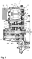
- FIG. 1 there is shown in longitudinal section, an embodiment of the hybrid traction device for a motor vehicle 1, which is the subject of the invention.
- These measures comprises a gearbox with parallel shafts 12, 13, the primary shaft 12 of which transmits the power of a thermal drive engine (not shown) to a secondary shaft 13 connected to the wheels of the vehicle. It also includes an electric machine 20. The machine 20 transmits its power in two gears to the secondary shaft 13 of the gearbox.
- the proposed device 1 constitutes a complete electric hybridization or hybrid traction device.
- This device is an extension of a conventional mechanical gearbox with parallel shafts. In the non-limiting embodiment illustrated by the figures, it is a manual gearbox. It can also be equipped with an automated clutch, or even be fully robotized.
- the proposed device can be produced with an automatic transmission, in particular with a double clutch.
- the gearbox to which an electrification module has just been added is made up of two casings, the clutch casing 10 and the mechanism casing 11. Inside the casings 10, 11, there are: the primary shaft 12, a first secondary shaft 13 arranged in the lower part for the forward gear ratios, a second secondary shaft 14 (see figure 2 ) arranged in the upper part for the reverse gear, a complete differential 15, a gear change device consisting of a selection and passage assembly 16 and sliding control forks 17.
- the hybridization, or the electrification of the box consists in integrating inside the latter an electric machine 20, the rotor of which is mounted on its shaft 21.
- This machine is supplied with current, and controlled, by a inverter 22 (arranged outside the casings 10, 11), connected thereto by the connector 23 which passes through the wall of the mechanism casing 11.
- the shaft of the rotor 21 supports a first toothing 25 which cooperates with the pinion 35 and makes it possible to transmit the power of the machine to a descent shaft 30.
- This shaft has two fixed pinions 31 and 32, which constitute the two driving pinions of a two-speed transmission, for the power supplied by the electric machine 20, when driving.
- the intermediate shaft 40 carries two idler gears 41, 42, and a fixed gear 46, a, driving a transfer gear 46, b rotating idler around the primary shaft 12 of the box.
- the pinions 41, 42 transmit the power of the electric machine to the secondary shaft 13. They are driven by fixed pinions 31, 32, of a descent shaft 30, receiving the power of the electric machine on two ratios of gearing down.
- the pinion 31 cooperates with the idler pinion 41 to produce the short ratio.
- the fixed pinion 32 cooperates with the pinion 42 to achieve the long ratio.
- the two sprockets 41 and 42 are crazy.
- the transfer pinion 46, b which is also idle, transmits to the secondary shaft 13 the power of the intermediate transmission shaft 40, driven by the electric machine 20.
- the central position corresponds to the disconnection of the electric machine. It is the representation of the figure 1 .
- the player clutches the pinion 41 to the shaft 40, and connects the electric machine 20 according to the short ratio. It is the representation of the picture 3 .
- the slider clutches the pinion 42 to the shaft 40 and connects the electric machine 20 to the long ratio.
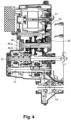
- THE figure 3 And 4 show the power path from the electrical machine 20 to the differential. In both figures, the transmission path of power between the electric machine 20 and the secondary shaft 13 of the box, passes the transfer pinion 46,b, turning idle around the primary shaft 12.
- the slider 43 disposed between the two idler gears 41, 42, of the intermediate shaft 40, is controlled by an actuator consisting of a fork 44 of a motor 45 and an intermediate mechanism, not shown. Lubrication, oil temperature management, and oil cleanliness are provided by the oil pump 50.
- the primary gearbox shaft 12 carries several idler gears, including the gear 46,b.
- the transfer gear 46,b is the idler gear of the third forward gear of the gearbox.
- the transfer pinion 46,b is the one which makes it possible to achieve the highest torque reduction of the electric machine on its short transmission ratio.
Landscapes
- Engineering & Computer Science (AREA)
- Mechanical Engineering (AREA)
- General Engineering & Computer Science (AREA)
- Chemical & Material Sciences (AREA)
- Combustion & Propulsion (AREA)
- Transportation (AREA)
- Hybrid Electric Vehicles (AREA)
- Electric Propulsion And Braking For Vehicles (AREA)
Description
- L'invention concerne un dispositif de traction hybride pour véhicule automobile comportant un moteur thermique avec sa boîte de vitesses manuelle ou robotisée, et une machine électrique connectée à la boîte de vitesses.
- Plus précisément, elle a pour objet un dispositif de traction hybride pour véhicule automobile comportant une boîte de vitesses à arbres parallèles, dont un arbre primaire transmet la puissance d'un moteur thermique d'entraînement à un arbre secondaire relié aux roues du véhicule, et une machine électrique qui transmet sa puissance sur deux rapports à l'arbre secondaire.
- Dans les véhicules hybrides comportant une double motorisation, thermique et électrique, la machine électrique est parfois liée au moteur thermique sur sa face dite « accessoires », comme l'alternateur. Pour augmenter la puissance électrique installée, et l'efficacité des échanges d'énergie de stockage en batterie et de restitution, il est plus avantageux de connecter la machine électrique à la boîte de vitesses. Cette disposition permet d'ouvrir ces véhicules à des possibilités nouvelles, en particulier le roulage en mode électrique, et à consommation réduite.
- On connaît des groupes motopropulseurs hybrides, dont la machine électrique est connectée à l'un ou à l'autre des arbres de la boîte de vitesses.
- Lorsqu'elle est liée avec l'arbre primaire, la machine électrique bénéficie des rapports de réduction de la boîte, mais perturbe l'inertie et la traînée équivalente de celui-ci. Pour que cette perturbation soit supportée par les dispositifs de synchronisation, il est nécessaire d'automatiser les changements de rapport. Un superviseur pilote alors la machine électrique pendant les changements de rapport, et limite, ou supprime, les effets indésirables d'inertie et de traînée. Dans certains cas, la machine électrique peut réaliser à elle seule la synchronisation, et les synchroniseurs classiques sont supprimés. Toutefois, cette architecture présente l'inconvénient important suivant : puisque la machine électrique est découplée des roues pendant le changement de rapport, elle ne peut pas assurer la continuité d'accélération complète, ou partielle, qui permettrait d'améliorer la prestation de passage des vitesses d'une boîte de vitesses robotisée.
- Lorsque la machine est liée à l'arbre secondaire, elle est capable de restituer (ou d'échanger) de l'énergie en permanence, y-compris pendant les changements de rapports. Elle ne bénéficie plus des rapports de la boîte, et a besoin d'une liaison dédiée avec l'arbre secondaire, par exemple une chaîne ou des couples de pignons.
- Lorsqu'elle est liée en permanence aux roues, la machine électrique peut devenir, dans certaines circonstances, la seule source de traction du véhicule. Pour augmenter l'apport en couple à la roue par cette machine à basse vitesse, ou pour faire décoller le véhicule à partir de l'arrêt en mode électrique, il faut une forte démultiplication. Pour continuer à utiliser la même machine à vitesse plus élevée, il faut une démultiplication plus faible. Enfin, pendant certaines phases de roulage, comme par exemple en vitesse stabilisée sur autoroute, il n'y a pas, ou très peu, d'échanges d'énergie entre la roue du véhicule et le système de motorisation électrique. Il peut alors être préférable de déconnecter la machine électrique, afin de limiter les pertes liées à son entraînement. Pour satisfaire à toutes ces exigences, le mécanisme de connexion de la machine électrique avec la roue, peut avantageusement disposer de deux rapports, et d'une position neutre.
- La publication
DE 10 2016 120 010 , décrit un groupe motopropulseur comportant un moteur thermique, une boîte de vitesses, et une machine électrique. L'arbre du rotor de la machine électrique porte un premier pignon qui met en mouvement un premier arbre comportant deux pignons fixes, à l'aide d'un pignon intermédiaire. Un deuxième arbre porte deux pignons fous, un groupe de crabotage, et possède à son extrémité un pignon fixe qui engrène avec la couronne du différentiel. A l'intérieur de la boîte de vitesses, qui est dédiée au moteur thermique, une seconde boîte à deux rapports dédiés à la machine électrique est ajoutée. La deuxième boîte de vitesses peut aussi être disposée à l'extérieur de la première. - Cet ensemble de transmission de puissance, forme une excroissance vers le bas, sous la boîte de vitesses, qui est difficilement compatible avec la garde au sol du véhicule.
- La publication
WO 2013/007886 A1 divulgue un groupe motopropulseur dans lequel la puissance d'une machine électrique s'applique également directement à la couronne d'un différentiel. - La publication
EP 2 679 424 A1 divulgue un groupe motopropulseur hybride ayant un chemin de transmission de puissance électrique alternatif. - Pour pallier cet inconvénient, l'invention propose un autre chemin de transmission de puissance entre la machine électrique et l'arbre secondaire.
- Conformément à l' invention comme définie dans la revendication 1, le chemin de transmission de puissance entre la machine électrique et l'arbre secondaire de la boîte passe par un pignon de transfert tournant fou autour de l'arbre primaire.
- Selon un mode de réalisation particulier de l'invention, le pignon de transfert est celui du troisième rapport de marche avant de la boîte.
- Ce pignon de transfert permet de réaliser la plus forte démultiplication de couple pour la machine électrique sur son rapport court de transmission.
- La présente invention sera mieux comprise à la lecture de la description suivante d'un mode de réalisation non limitatif de celle-ci, en se reportant aux dessins annexés, sur lesquels.
- [
Fig. 1 ] est une vue en coupe longitudinale du dispositif complet, en position de rapport neutre. - [
Fig. 2 ] est une vue en coupe transversale du dispositif complet. - [
Fig. 3 ] est une vue en coupe longitudinale du dispositif complet seul, en position de rapport court, montrant le chemin de transmission de puissance. - [
Fig. 4 ] est une vue en coupe longitudinale du dispositif complet seul, en position de rapport long, montrant le chemin de transmission de puissance. -
Repères 1 Mécanisme de transmission de puissance 10 Carter d'embrayage 11 Carter de mécanisme 12 Arbre primaire 13 Arbre secondaire bas des rapports avant 14 Arbre secondaire haut de marche arrière 15 Différentiel 16 Mécanismes de sélection des vitesses 17 Fourchettes de commande des baladeurs 20 Machine électrique 21 Arbre rotor de machine électrique 22 Onduleur 23 Connecteur 25 Pignon, fixe sur arbre rotor 30 Arbre de descente 31 Pignon fixe du rapport court 32 Pignon fixe du rapport long 35 Pignon fixe de descente 40 Arbre intermédiaire 41 Pignon fou rapport court 42 Pignon fou rapport long 43 Groupe de crabotage 44 Fourchette de commande du groupe de crabotage 43 45 Moteur d'actionnement fourchette 44 46,a Pignon fixe de sortie 46,b Pignon fou du rapport de 3ème, ou pignon de transfert 46,c Pignon fixe du rapport de 3ème 50 Pompe à huile - Sur la
figure 1 , on a représenté en coupe longitudinale, un mode de réalisation du dispositif de traction hybride pour véhicule automobile 1, faisant l'objet de l'invention. Ce dispositif comporte une boîte de vitesses à arbres parallèles 12, 13, dont l'arbre primaire 12 transmet la puissance d'un moteur thermique d'entraînement (non représenté) à un arbre secondaire 13 relié aux roues du véhicule. Il comporte également une machine électrique 20. La machine 20 transmet sa puissance sur deux rapports à l'arbre secondaire 13 de la boîte de vitesses. Le dispositif 1 proposé constitue un dispositif d'hybridation électrique ou de traction hybride complet. Ce dispositif est une extension d'une boîte de vitesses mécanique classique à arbres parallèles. Dans l'exemple de réalisation non limitatif illustré par les figures, c'est une boîte de vitesses manuelle. Elle peut aussi être équipée d'un embrayage automatisé, ou même être entièrement robotisée. Sans sortir du cadre de l'invention, le dispositif proposé peut être réalisé avec une transmission automatique, notamment à double embrayage. La boîte de vitesses à laquelle on vient rapporter un module d'électrification est composée de deux carters, le carter d'embrayage 10 et le carter de mécanisme 11. A l'intérieur des carters 10, 11, on trouve : l'arbre primaire 12, un premier arbre secondaire 13 agencé en partie basse pour les rapports de marche avant, un second arbre secondaire 14 (voirfigure 2 ) agencé en partie haute pour le rapport de marche arrière, un différentiel complet 15, un dispositif de changements de rapports composé d'un ensemble de sélection et passage 16 et des fourchettes de commande des baladeurs 17. - L'hybridation, ou l'électrification de la boîte, consiste à intégrer à l'intérieur de celle-ci une machine électrique 20, dont le rotor est monté sur son arbre 21. Cette machine est alimentée en courant, et commandée, par un onduleur 22 (disposé à l'extérieur des carters 10, 11), liée à celle-ci par le connecteur 23 qui traverse la paroi du carter de mécanisme 11. L'arbre du rotor 21 supporte une première denture 25 qui coopère avec le pignon 35 et permet de transmettre la puissance de la machine à un arbre de descente 30. Cet arbre possède deux pignons fixes 31 et 32, qui constituent les deux pignons menants d'une transmission à deux rapports, pour la puissance fournie par la machine électrique 20, lorsqu'elle est motrice.
- L'arbre intermédiaire 40 porte deux pignons fous 41, 42, et un pignon fixe 46,a, entraînant un pignon de transfert 46,b tournant fou autour de l'arbre primaire 12 de la boîte. Les pignons 41, 42, transmettent la puissance de la machine électrique à l'arbre secondaire 13. Ils sont entraînés par des pignons fixes 31, 32, d'un arbre de descente 30, recevant la puissance de la machine électrique sur deux rapports de démultiplication. Le pignon 31 coopère avec le pignon fou 41 pour réaliser le rapport court. Le pignon fixe 32 coopère avec le pignon 42 pour réaliser le rapport long. Les deux pignons 41 et 42 sont fous. Le pignon de transfert 46,b, qui est également fou, transmet à l'arbre secondaire 13 la puissance de l'arbre intermédiaire de transmission 40, entraîné par la machine électrique 20.
- Entre les deux pignons 41, 42 est agencé un groupe de couplage 43 à trois positions : la position centrale correspond à la déconnexion de la machine électrique. C'est la représentation de la
figure 1 . A gauche, le baladeur crabote le pignon 41 à l'arbre 40, et connecte la machine électrique 20 selon le rapport court. C'est la représentation de lafigure 3 . on l'on montre la transmission de puissance de la machine au différentiel 15. A droite, le baladeur crabote le pignon 42 à l'arbre 40 et connecte la machine électrique 20 sur le rapport long. C'est la configuration de lafigure 4 . Lesfigures 3 et4 montrent le chemin de puissance, de la machine électrique 20 au différentiel. Sur les deux figures, le chemin de transmission de puissance entre la machine 20 électrique et l'arbre secondaire 13 de la boîte, passe le pignon de transfert 46,b, tournant fou autour de l'arbre primaire 12. - Le baladeur 43, disposé entre les deux pignons fous 41, 42, de l'arbre intermédiaire 40, est commandé par un actionneur composé d'une fourchette 44 d'un moteur 45 et d'un mécanisme intermédiaire non représenté. La lubrification, la gestion de la température de l'huile, et la propreté de l'huile, sont assurées par la pompe à huile 50.
- Dans le mode de réalisation non limitatif de l'invention illustré par les figures, l'arbre primaire 12 de boîte porte plusieurs pignons fous dont le pignon 46,b. Le pignon de transfert 46,b est le pignon fou du troisième rapport de marche avant de la boîte. Dans cette architecture, le pignon de transfert 46,b est celui qui permet de réaliser la plus forte démultiplication de couple de la machine électrique sur son rapport court de transmission.
Claims (4)
- Dispositif de traction hybride (1) pour véhicule automobile comportant une boîte de vitesses à arbres parallèles, dont un arbre primaire (12) transmet la puissance d'un moteur thermique d'entraînement à un arbre secondaire (13) relié aux roues du véhicule, et une machine électrique (20) qui transmet sa puissance sur deux rapports à l'arbre secondaire (13) de la boîte de vitesses, dans lequel le chemin de transmission de puissance entre la machine électrique (20) et l'arbre secondaire (13), passe par un arbre de descente (30) recevant la puissance de la machine électrique (20), par un arbre intermédiaire de transmission (40), et par un pignon de transfert (46,b) tournant fou autour de l'arbre primaire (12), caractérisé en ce que l'arbre intermédiaire (40) porte deux pignons fous (41, 42) entraînés par des pignons fixes (31, 32) de l'arbre de descente (30) recevant la puissance de la machine électrique (20), et un pignon fixe (46,a) entraînant le pignon de transfert (46,b).
- Dispositif de traction hybride (1) selon la revendication 1, caractérisé en ce que les deux pignons fous (41, 42) de l'arbre intermédiaire, transmettent la puissance de la machine électrique (20) à l'arbre secondaire (13) de la boîte sur un rapport court et sur un rapport long de transmission.3
- Dispositif de traction hybride (1) selon la revendication 1 ou 2, caractérisé en ce que l'arbre primaire (12) de la boîte porte plusieurs pignons fous dont le pignon(46,b), le pignon de transfert (46,b) étant celui du troisième rapport de marche avant de la boîte.
- Dispositif de traction hybride selon la revendication 2 ou 3, caractérisé en ce que le pignon de transfert (46,b) permet de réaliser la plus forte démultiplication de couple pour la machine électrique (20) sur son rapport court de transmission.
Applications Claiming Priority (1)
| Application Number | Priority Date | Filing Date | Title |
|---|---|---|---|
| FR1901764A FR3093034B1 (fr) | 2019-02-21 | 2019-02-21 | Dispositif de traction hybride de vehicule automobile et mecanisme de transmission de puissance |
Publications (2)
| Publication Number | Publication Date |
|---|---|
| EP3699008A1 EP3699008A1 (fr) | 2020-08-26 |
| EP3699008B1 true EP3699008B1 (fr) | 2023-08-23 |
Family
ID=67441281
Family Applications (1)
| Application Number | Title | Priority Date | Filing Date |
|---|---|---|---|
| EP20153655.4A Active EP3699008B1 (fr) | 2019-02-21 | 2020-01-24 | Dispositif de traction hybride de véhicule automobile |
Country Status (2)
| Country | Link |
|---|---|
| EP (1) | EP3699008B1 (fr) |
| FR (1) | FR3093034B1 (fr) |
Families Citing this family (1)
| Publication number | Priority date | Publication date | Assignee | Title |
|---|---|---|---|---|
| CN121088794A (zh) * | 2025-11-06 | 2025-12-09 | 山东博峻智能科技有限公司 | 一种电动装载机变速箱的自动换档结构 |
Family Cites Families (4)
| Publication number | Priority date | Publication date | Assignee | Title |
|---|---|---|---|---|
| FR2977838B1 (fr) * | 2011-07-13 | 2013-10-11 | IFP Energies Nouvelles | Groupe motopropulseur pour vehicule automobile a entrainement hybride |
| ITTO20120565A1 (it) * | 2012-06-26 | 2013-12-27 | Oerlikon Graziano Spa | Trasmissione ibrida per veicolo a motore |
| FR3031477A1 (fr) * | 2015-01-08 | 2016-07-15 | Peugeot Citroen Automobiles Sa | Boite de vitesses pour vehicule automobile |
| DE102016120010A1 (de) | 2016-10-20 | 2018-04-26 | Getrag Ford Transmissions Gmbh | Antriebsbaugruppe mit E-Maschine für ein Kraftfahrzeug |
-
2019
- 2019-02-21 FR FR1901764A patent/FR3093034B1/fr active Active
-
2020
- 2020-01-24 EP EP20153655.4A patent/EP3699008B1/fr active Active
Also Published As
| Publication number | Publication date |
|---|---|
| FR3093034B1 (fr) | 2022-01-28 |
| FR3093034A1 (fr) | 2020-08-28 |
| EP3699008A1 (fr) | 2020-08-26 |
Similar Documents
| Publication | Publication Date | Title |
|---|---|---|
| EP1042135B1 (fr) | Dispositif de transmission de vehicule automobile a motorisation hybride comportant un accouplement commande du moteur electrique | |
| EP1097830B1 (fr) | Groupe motopropulseur hybride comportant au moins deux trains épicycloidaux | |
| FR2945599A1 (fr) | Boite de vitesse a double embrayage a sept vitesses | |
| EP1232891A1 (fr) | Système de transmission de mouvement pour véhicules à propulsion hybride | |
| FR2976526A1 (fr) | Groupe motopropulseur | |
| FR2946291A1 (fr) | Groupe motopropulseur pour vehicule electrique a deux arbres permettant d'obtenir deux rapports de transmission | |
| FR3062089A1 (fr) | Systeme de transmission de puissance et vehicule avec systeme de transmission de puissance | |
| EP1755913A1 (fr) | Groupe motopropulseur hybride et son procede de fonctionnement | |
| EP2209660B1 (fr) | Dispositif de transmission de puissance entre une sortie d'un moteur thermique et un arbre de roues et utilisation de ce dispositif | |
| WO2012042137A1 (fr) | Groupe motopropulseur hybride a arbres d'entree coaxiaux et procede de commande correspondant | |
| EP3699008B1 (fr) | Dispositif de traction hybride de véhicule automobile | |
| EP4011670A1 (fr) | Module hybride | |
| FR2946293A1 (fr) | Groupe motopropulseur pour vehicule electrique a trois arbres permettant d'obtenir deux rapports de transmission | |
| EP3277531B1 (fr) | Groupe motopropulseur hybride comportant deux moteurs electriques et un moteur thermique non coaxiaux | |
| EP3741602A1 (fr) | Dispositif de traction hybride de vehicule automobile | |
| FR3096310A1 (fr) | Dispositif de traction hybride de vehicule automobile a transmission par chaine | |
| WO2010007291A1 (fr) | Boite de vitesses hybride a arbres parallelles | |
| EP4094963A1 (fr) | Sous-ensemble hybride d'entraînement d'un véhicule, groupe moteur hybride et procédé d'entraînement hybride | |
| EP3957506A1 (fr) | Dispositif de traction hybride de vehicule automobile a transmission par chaine | |
| WO2021170523A1 (fr) | Module motorisé, sous-ensemble hybride d'entrainement d'un véhicule, et méthode d'engagement d'un crabot dans ledit sous-ensemble hybride | |
| FR2543245A1 (fr) | Transmission a variateur | |
| FR2976039A3 (fr) | Boite de vitesses a huit rapports a double embrayage | |
| FR2972516A1 (fr) | Procede de changement de rapport de vitesses sous couple sur une boite de vitesse a double embrayage, dispositif mettant en œuvre ce procede et vehicule incorporant un tel dispositif | |
| FR2819873A1 (fr) | Boite de vitesses a deux arbres primaires paralleles | |
| FR2951995A1 (fr) | Groupe motopropulseur hybride multirapports a deux machines electriques |
Legal Events
| Date | Code | Title | Description |
|---|---|---|---|
| PUAI | Public reference made under article 153(3) epc to a published international application that has entered the european phase |
Free format text: ORIGINAL CODE: 0009012 |
|
| STAA | Information on the status of an ep patent application or granted ep patent |
Free format text: STATUS: THE APPLICATION HAS BEEN PUBLISHED |
|
| AK | Designated contracting states |
Kind code of ref document: A1 Designated state(s): AL AT BE BG CH CY CZ DE DK EE ES FI FR GB GR HR HU IE IS IT LI LT LU LV MC MK MT NL NO PL PT RO RS SE SI SK SM TR |
|
| AX | Request for extension of the european patent |
Extension state: BA ME |
|
| STAA | Information on the status of an ep patent application or granted ep patent |
Free format text: STATUS: REQUEST FOR EXAMINATION WAS MADE |
|
| 17P | Request for examination filed |
Effective date: 20200923 |
|
| RBV | Designated contracting states (corrected) |
Designated state(s): AL AT BE BG CH CY CZ DE DK EE ES FI FR GB GR HR HU IE IS IT LI LT LU LV MC MK MT NL NO PL PT RO RS SE SI SK SM TR |
|
| STAA | Information on the status of an ep patent application or granted ep patent |
Free format text: STATUS: EXAMINATION IS IN PROGRESS |
|
| RAP3 | Party data changed (applicant data changed or rights of an application transferred) |
Owner name: RENAULT S.A.S |
|
| 17Q | First examination report despatched |
Effective date: 20220301 |
|
| RAP3 | Party data changed (applicant data changed or rights of an application transferred) |
Owner name: RENAULT S.A.S |
|
| GRAP | Despatch of communication of intention to grant a patent |
Free format text: ORIGINAL CODE: EPIDOSNIGR1 |
|
| STAA | Information on the status of an ep patent application or granted ep patent |
Free format text: STATUS: GRANT OF PATENT IS INTENDED |
|
| INTG | Intention to grant announced |
Effective date: 20230419 |
|
| GRAS | Grant fee paid |
Free format text: ORIGINAL CODE: EPIDOSNIGR3 |
|
| P01 | Opt-out of the competence of the unified patent court (upc) registered |
Effective date: 20230608 |
|
| GRAA | (expected) grant |
Free format text: ORIGINAL CODE: 0009210 |
|
| STAA | Information on the status of an ep patent application or granted ep patent |
Free format text: STATUS: THE PATENT HAS BEEN GRANTED |
|
| AK | Designated contracting states |
Kind code of ref document: B1 Designated state(s): AL AT BE BG CH CY CZ DE DK EE ES FI FR GB GR HR HU IE IS IT LI LT LU LV MC MK MT NL NO PL PT RO RS SE SI SK SM TR |
|
| REG | Reference to a national code |
Ref country code: GB Ref legal event code: FG4D Free format text: NOT ENGLISH |
|
| REG | Reference to a national code |
Ref country code: CH Ref legal event code: EP |
|
| REG | Reference to a national code |
Ref country code: IE Ref legal event code: FG4D Free format text: LANGUAGE OF EP DOCUMENT: FRENCH |
|
| REG | Reference to a national code |
Ref country code: DE Ref legal event code: R096 Ref document number: 602020016010 Country of ref document: DE |
|
| REG | Reference to a national code |
Ref country code: LT Ref legal event code: MG9D |
|
| REG | Reference to a national code |
Ref country code: NL Ref legal event code: MP Effective date: 20230823 |
|
| REG | Reference to a national code |
Ref country code: AT Ref legal event code: MK05 Ref document number: 1602195 Country of ref document: AT Kind code of ref document: T Effective date: 20230823 |
|
| PG25 | Lapsed in a contracting state [announced via postgrant information from national office to epo] |
Ref country code: GR Free format text: LAPSE BECAUSE OF FAILURE TO SUBMIT A TRANSLATION OF THE DESCRIPTION OR TO PAY THE FEE WITHIN THE PRESCRIBED TIME-LIMIT Effective date: 20231124 |
|
| PG25 | Lapsed in a contracting state [announced via postgrant information from national office to epo] |
Ref country code: IS Free format text: LAPSE BECAUSE OF FAILURE TO SUBMIT A TRANSLATION OF THE DESCRIPTION OR TO PAY THE FEE WITHIN THE PRESCRIBED TIME-LIMIT Effective date: 20231223 |
|
| REG | Reference to a national code |
Ref country code: GB Ref legal event code: 732E Free format text: REGISTERED BETWEEN 20231228 AND 20240103 |
|
| PG25 | Lapsed in a contracting state [announced via postgrant information from national office to epo] |
Ref country code: SE Free format text: LAPSE BECAUSE OF FAILURE TO SUBMIT A TRANSLATION OF THE DESCRIPTION OR TO PAY THE FEE WITHIN THE PRESCRIBED TIME-LIMIT Effective date: 20230823 Ref country code: RS Free format text: LAPSE BECAUSE OF FAILURE TO SUBMIT A TRANSLATION OF THE DESCRIPTION OR TO PAY THE FEE WITHIN THE PRESCRIBED TIME-LIMIT Effective date: 20230823 Ref country code: PT Free format text: LAPSE BECAUSE OF FAILURE TO SUBMIT A TRANSLATION OF THE DESCRIPTION OR TO PAY THE FEE WITHIN THE PRESCRIBED TIME-LIMIT Effective date: 20231226 Ref country code: NO Free format text: LAPSE BECAUSE OF FAILURE TO SUBMIT A TRANSLATION OF THE DESCRIPTION OR TO PAY THE FEE WITHIN THE PRESCRIBED TIME-LIMIT Effective date: 20231123 Ref country code: NL Free format text: LAPSE BECAUSE OF FAILURE TO SUBMIT A TRANSLATION OF THE DESCRIPTION OR TO PAY THE FEE WITHIN THE PRESCRIBED TIME-LIMIT Effective date: 20230823 Ref country code: LV Free format text: LAPSE BECAUSE OF FAILURE TO SUBMIT A TRANSLATION OF THE DESCRIPTION OR TO PAY THE FEE WITHIN THE PRESCRIBED TIME-LIMIT Effective date: 20230823 Ref country code: LT Free format text: LAPSE BECAUSE OF FAILURE TO SUBMIT A TRANSLATION OF THE DESCRIPTION OR TO PAY THE FEE WITHIN THE PRESCRIBED TIME-LIMIT Effective date: 20230823 Ref country code: IS Free format text: LAPSE BECAUSE OF FAILURE TO SUBMIT A TRANSLATION OF THE DESCRIPTION OR TO PAY THE FEE WITHIN THE PRESCRIBED TIME-LIMIT Effective date: 20231223 Ref country code: HR Free format text: LAPSE BECAUSE OF FAILURE TO SUBMIT A TRANSLATION OF THE DESCRIPTION OR TO PAY THE FEE WITHIN THE PRESCRIBED TIME-LIMIT Effective date: 20230823 Ref country code: GR Free format text: LAPSE BECAUSE OF FAILURE TO SUBMIT A TRANSLATION OF THE DESCRIPTION OR TO PAY THE FEE WITHIN THE PRESCRIBED TIME-LIMIT Effective date: 20231124 Ref country code: FI Free format text: LAPSE BECAUSE OF FAILURE TO SUBMIT A TRANSLATION OF THE DESCRIPTION OR TO PAY THE FEE WITHIN THE PRESCRIBED TIME-LIMIT Effective date: 20230823 Ref country code: AT Free format text: LAPSE BECAUSE OF FAILURE TO SUBMIT A TRANSLATION OF THE DESCRIPTION OR TO PAY THE FEE WITHIN THE PRESCRIBED TIME-LIMIT Effective date: 20230823 |
|
| PG25 | Lapsed in a contracting state [announced via postgrant information from national office to epo] |
Ref country code: PL Free format text: LAPSE BECAUSE OF FAILURE TO SUBMIT A TRANSLATION OF THE DESCRIPTION OR TO PAY THE FEE WITHIN THE PRESCRIBED TIME-LIMIT Effective date: 20230823 |
|
| PG25 | Lapsed in a contracting state [announced via postgrant information from national office to epo] |
Ref country code: ES Free format text: LAPSE BECAUSE OF FAILURE TO SUBMIT A TRANSLATION OF THE DESCRIPTION OR TO PAY THE FEE WITHIN THE PRESCRIBED TIME-LIMIT Effective date: 20230823 |
|
| PG25 | Lapsed in a contracting state [announced via postgrant information from national office to epo] |
Ref country code: SM Free format text: LAPSE BECAUSE OF FAILURE TO SUBMIT A TRANSLATION OF THE DESCRIPTION OR TO PAY THE FEE WITHIN THE PRESCRIBED TIME-LIMIT Effective date: 20230823 Ref country code: RO Free format text: LAPSE BECAUSE OF FAILURE TO SUBMIT A TRANSLATION OF THE DESCRIPTION OR TO PAY THE FEE WITHIN THE PRESCRIBED TIME-LIMIT Effective date: 20230823 Ref country code: ES Free format text: LAPSE BECAUSE OF FAILURE TO SUBMIT A TRANSLATION OF THE DESCRIPTION OR TO PAY THE FEE WITHIN THE PRESCRIBED TIME-LIMIT Effective date: 20230823 Ref country code: EE Free format text: LAPSE BECAUSE OF FAILURE TO SUBMIT A TRANSLATION OF THE DESCRIPTION OR TO PAY THE FEE WITHIN THE PRESCRIBED TIME-LIMIT Effective date: 20230823 Ref country code: DK Free format text: LAPSE BECAUSE OF FAILURE TO SUBMIT A TRANSLATION OF THE DESCRIPTION OR TO PAY THE FEE WITHIN THE PRESCRIBED TIME-LIMIT Effective date: 20230823 Ref country code: CZ Free format text: LAPSE BECAUSE OF FAILURE TO SUBMIT A TRANSLATION OF THE DESCRIPTION OR TO PAY THE FEE WITHIN THE PRESCRIBED TIME-LIMIT Effective date: 20230823 Ref country code: SK Free format text: LAPSE BECAUSE OF FAILURE TO SUBMIT A TRANSLATION OF THE DESCRIPTION OR TO PAY THE FEE WITHIN THE PRESCRIBED TIME-LIMIT Effective date: 20230823 |
|
| REG | Reference to a national code |
Ref country code: DE Ref legal event code: R081 Ref document number: 602020016010 Country of ref document: DE Owner name: NEW H POWERTRAIN HOLDING, S.L.U., ES Free format text: FORMER OWNER: RENAULT S.A.S, BOULOGNE-BILLANCOURT, FR |
|
| REG | Reference to a national code |
Ref country code: DE Ref legal event code: R097 Ref document number: 602020016010 Country of ref document: DE |
|
| PG25 | Lapsed in a contracting state [announced via postgrant information from national office to epo] |
Ref country code: IT Free format text: LAPSE BECAUSE OF FAILURE TO SUBMIT A TRANSLATION OF THE DESCRIPTION OR TO PAY THE FEE WITHIN THE PRESCRIBED TIME-LIMIT Effective date: 20230823 |
|
| PLBE | No opposition filed within time limit |
Free format text: ORIGINAL CODE: 0009261 |
|
| STAA | Information on the status of an ep patent application or granted ep patent |
Free format text: STATUS: NO OPPOSITION FILED WITHIN TIME LIMIT |
|
| 26N | No opposition filed |
Effective date: 20240524 |
|
| PG25 | Lapsed in a contracting state [announced via postgrant information from national office to epo] |
Ref country code: SI Free format text: LAPSE BECAUSE OF FAILURE TO SUBMIT A TRANSLATION OF THE DESCRIPTION OR TO PAY THE FEE WITHIN THE PRESCRIBED TIME-LIMIT Effective date: 20230823 |
|
| PG25 | Lapsed in a contracting state [announced via postgrant information from national office to epo] |
Ref country code: MC Free format text: LAPSE BECAUSE OF FAILURE TO SUBMIT A TRANSLATION OF THE DESCRIPTION OR TO PAY THE FEE WITHIN THE PRESCRIBED TIME-LIMIT Effective date: 20230823 |
|
| PG25 | Lapsed in a contracting state [announced via postgrant information from national office to epo] |
Ref country code: MC Free format text: LAPSE BECAUSE OF FAILURE TO SUBMIT A TRANSLATION OF THE DESCRIPTION OR TO PAY THE FEE WITHIN THE PRESCRIBED TIME-LIMIT Effective date: 20230823 |
|
| REG | Reference to a national code |
Ref country code: CH Ref legal event code: PL |
|
| PG25 | Lapsed in a contracting state [announced via postgrant information from national office to epo] |
Ref country code: LU Free format text: LAPSE BECAUSE OF NON-PAYMENT OF DUE FEES Effective date: 20240124 |
|
| PG25 | Lapsed in a contracting state [announced via postgrant information from national office to epo] |
Ref country code: LU Free format text: LAPSE BECAUSE OF NON-PAYMENT OF DUE FEES Effective date: 20240124 |
|
| PG25 | Lapsed in a contracting state [announced via postgrant information from national office to epo] |
Ref country code: BE Free format text: LAPSE BECAUSE OF NON-PAYMENT OF DUE FEES Effective date: 20240131 |
|
| PG25 | Lapsed in a contracting state [announced via postgrant information from national office to epo] |
Ref country code: CH Free format text: LAPSE BECAUSE OF NON-PAYMENT OF DUE FEES Effective date: 20240131 |
|
| PG25 | Lapsed in a contracting state [announced via postgrant information from national office to epo] |
Ref country code: CH Free format text: LAPSE BECAUSE OF NON-PAYMENT OF DUE FEES Effective date: 20240131 Ref country code: BE Free format text: LAPSE BECAUSE OF NON-PAYMENT OF DUE FEES Effective date: 20240131 |
|
| REG | Reference to a national code |
Ref country code: BE Ref legal event code: MM Effective date: 20240131 |
|
| PG25 | Lapsed in a contracting state [announced via postgrant information from national office to epo] |
Ref country code: BG Free format text: LAPSE BECAUSE OF FAILURE TO SUBMIT A TRANSLATION OF THE DESCRIPTION OR TO PAY THE FEE WITHIN THE PRESCRIBED TIME-LIMIT Effective date: 20230823 |
|
| PG25 | Lapsed in a contracting state [announced via postgrant information from national office to epo] |
Ref country code: BG Free format text: LAPSE BECAUSE OF FAILURE TO SUBMIT A TRANSLATION OF THE DESCRIPTION OR TO PAY THE FEE WITHIN THE PRESCRIBED TIME-LIMIT Effective date: 20230823 |
|
| PG25 | Lapsed in a contracting state [announced via postgrant information from national office to epo] |
Ref country code: IE Free format text: LAPSE BECAUSE OF NON-PAYMENT OF DUE FEES Effective date: 20240124 |
|
| PG25 | Lapsed in a contracting state [announced via postgrant information from national office to epo] |
Ref country code: IE Free format text: LAPSE BECAUSE OF NON-PAYMENT OF DUE FEES Effective date: 20240124 |
|
| PG25 | Lapsed in a contracting state [announced via postgrant information from national office to epo] |
Ref country code: CY Free format text: LAPSE BECAUSE OF FAILURE TO SUBMIT A TRANSLATION OF THE DESCRIPTION OR TO PAY THE FEE WITHIN THE PRESCRIBED TIME-LIMIT; INVALID AB INITIO Effective date: 20200124 |
|
| PG25 | Lapsed in a contracting state [announced via postgrant information from national office to epo] |
Ref country code: HU Free format text: LAPSE BECAUSE OF FAILURE TO SUBMIT A TRANSLATION OF THE DESCRIPTION OR TO PAY THE FEE WITHIN THE PRESCRIBED TIME-LIMIT; INVALID AB INITIO Effective date: 20200124 |
|
| PG25 | Lapsed in a contracting state [announced via postgrant information from national office to epo] |
Ref country code: TR Free format text: LAPSE BECAUSE OF FAILURE TO SUBMIT A TRANSLATION OF THE DESCRIPTION OR TO PAY THE FEE WITHIN THE PRESCRIBED TIME-LIMIT Effective date: 20230823 |
|
| PGFP | Annual fee paid to national office [announced via postgrant information from national office to epo] |
Ref country code: GB Payment date: 20260123 Year of fee payment: 7 |
|
| PGFP | Annual fee paid to national office [announced via postgrant information from national office to epo] |
Ref country code: DE Payment date: 20260121 Year of fee payment: 7 |
|
| PGFP | Annual fee paid to national office [announced via postgrant information from national office to epo] |
Ref country code: FR Payment date: 20260123 Year of fee payment: 7 |