EP3698908A2 - Banc de serrage pour machines à dupliquer les clés et machine à dupliquer les clés - Google Patents
Banc de serrage pour machines à dupliquer les clés et machine à dupliquer les clés Download PDFInfo
- Publication number
- EP3698908A2 EP3698908A2 EP20154238.8A EP20154238A EP3698908A2 EP 3698908 A2 EP3698908 A2 EP 3698908A2 EP 20154238 A EP20154238 A EP 20154238A EP 3698908 A2 EP3698908 A2 EP 3698908A2
- Authority
- EP
- European Patent Office
- Prior art keywords
- rotary
- hole
- axis
- component
- base
- Prior art date
- Legal status (The legal status is an assumption and is not a legal conclusion. Google has not performed a legal analysis and makes no representation as to the accuracy of the status listed.)
- Granted
Links
- 230000007246 mechanism Effects 0.000 claims description 36
- 230000001105 regulatory effect Effects 0.000 claims description 33
- 238000003801 milling Methods 0.000 claims description 16
- 238000009434 installation Methods 0.000 claims description 15
- 238000005299 abrasion Methods 0.000 claims description 5
- RYGMFSIKBFXOCR-UHFFFAOYSA-N Copper Chemical compound [Cu] RYGMFSIKBFXOCR-UHFFFAOYSA-N 0.000 claims description 4
- 229910052802 copper Inorganic materials 0.000 claims description 4
- 239000010949 copper Substances 0.000 claims description 4
- 239000000463 material Substances 0.000 claims description 4
- 239000002131 composite material Substances 0.000 abstract description 5
- 238000000034 method Methods 0.000 description 13
- 230000008569 process Effects 0.000 description 9
- 238000010586 diagram Methods 0.000 description 8
- 230000008901 benefit Effects 0.000 description 3
- 238000005516 engineering process Methods 0.000 description 3
- 230000002708 enhancing effect Effects 0.000 description 2
- 238000005096 rolling process Methods 0.000 description 2
- 230000000712 assembly Effects 0.000 description 1
- 238000000429 assembly Methods 0.000 description 1
- 230000008859 change Effects 0.000 description 1
- 238000006073 displacement reaction Methods 0.000 description 1
- 230000009916 joint effect Effects 0.000 description 1
- 238000003754 machining Methods 0.000 description 1
- 239000011295 pitch Substances 0.000 description 1
- 230000000717 retained effect Effects 0.000 description 1
Images


Classifications
-
- B—PERFORMING OPERATIONS; TRANSPORTING
- B23—MACHINE TOOLS; METAL-WORKING NOT OTHERWISE PROVIDED FOR
- B23Q—DETAILS, COMPONENTS, OR ACCESSORIES FOR MACHINE TOOLS, e.g. ARRANGEMENTS FOR COPYING OR CONTROLLING; MACHINE TOOLS IN GENERAL CHARACTERISED BY THE CONSTRUCTION OF PARTICULAR DETAILS OR COMPONENTS; COMBINATIONS OR ASSOCIATIONS OF METAL-WORKING MACHINES, NOT DIRECTED TO A PARTICULAR RESULT
- B23Q5/00—Driving or feeding mechanisms; Control arrangements therefor
- B23Q5/22—Feeding members carrying tools or work
- B23Q5/34—Feeding other members supporting tools or work, e.g. saddles, tool-slides, through mechanical transmission
-
- B—PERFORMING OPERATIONS; TRANSPORTING
- B23—MACHINE TOOLS; METAL-WORKING NOT OTHERWISE PROVIDED FOR
- B23C—MILLING
- B23C3/00—Milling particular work; Special milling operations; Machines therefor
- B23C3/28—Grooving workpieces
- B23C3/35—Milling grooves in keys
- B23C3/355—Holders for the template keys
-
- B—PERFORMING OPERATIONS; TRANSPORTING
- B23—MACHINE TOOLS; METAL-WORKING NOT OTHERWISE PROVIDED FOR
- B23C—MILLING
- B23C3/00—Milling particular work; Special milling operations; Machines therefor
-
- B—PERFORMING OPERATIONS; TRANSPORTING
- B23—MACHINE TOOLS; METAL-WORKING NOT OTHERWISE PROVIDED FOR
- B23Q—DETAILS, COMPONENTS, OR ACCESSORIES FOR MACHINE TOOLS, e.g. ARRANGEMENTS FOR COPYING OR CONTROLLING; MACHINE TOOLS IN GENERAL CHARACTERISED BY THE CONSTRUCTION OF PARTICULAR DETAILS OR COMPONENTS; COMBINATIONS OR ASSOCIATIONS OF METAL-WORKING MACHINES, NOT DIRECTED TO A PARTICULAR RESULT
- B23Q3/00—Devices holding, supporting, or positioning work or tools, of a kind normally removable from the machine
- B23Q3/02—Devices holding, supporting, or positioning work or tools, of a kind normally removable from the machine for mounting on a work-table, tool-slide, or analogous part
- B23Q3/06—Work-clamping means
- B23Q3/061—Work-clamping means adapted for holding a plurality of workpieces
-
- B—PERFORMING OPERATIONS; TRANSPORTING
- B23—MACHINE TOOLS; METAL-WORKING NOT OTHERWISE PROVIDED FOR
- B23Q—DETAILS, COMPONENTS, OR ACCESSORIES FOR MACHINE TOOLS, e.g. ARRANGEMENTS FOR COPYING OR CONTROLLING; MACHINE TOOLS IN GENERAL CHARACTERISED BY THE CONSTRUCTION OF PARTICULAR DETAILS OR COMPONENTS; COMBINATIONS OR ASSOCIATIONS OF METAL-WORKING MACHINES, NOT DIRECTED TO A PARTICULAR RESULT
- B23Q3/00—Devices holding, supporting, or positioning work or tools, of a kind normally removable from the machine
- B23Q3/02—Devices holding, supporting, or positioning work or tools, of a kind normally removable from the machine for mounting on a work-table, tool-slide, or analogous part
- B23Q3/06—Work-clamping means
- B23Q3/062—Work-clamping means adapted for holding workpieces having a special form or being made from a special material
-
- B—PERFORMING OPERATIONS; TRANSPORTING
- B23—MACHINE TOOLS; METAL-WORKING NOT OTHERWISE PROVIDED FOR
- B23C—MILLING
- B23C2270/00—Details of milling machines, milling processes or milling tools not otherwise provided for
- B23C2270/08—Clamping mechanisms or provision for clamping
Definitions
- the present invention relates to the technical field of key duplicating equipment, particularly a clamp bench for key duplicating machines.
- the known technologies add a rotary shaft and a clutch buckle to the key duplicating machine bench to add a space for relative motion between the clamp installation plate and the bench.
- the user can pull the handle on the side of the clamp installation plate up and down to rotate the plate in relation to the bench, or pull the bench up and down to rotate the bench in relation to the horizontal miller.
- the user can hold the handle of the clamp installation plate and the bench with two hands respectively to achieve a simultaneous composite motion of the clamp installation plate around two axes, thereby increasing the angle of contact between the key and the cutter, in order to process the bevel key.
- this method also has a disadvantage: when working, the user will have to hold the bench and the installation plate with two hands respectively to ensure stable tooth feeding during key processing, while for the axial feeding of the key, the user will have to release the bench or installation plate with one hand after processing one tooth and use the free hand to complete the axial feeding, or ask another person to help complete the work. This means that the user cannot simultaneously complete the horizontal and axial feeding, so this method is less convenient and lacks continuity.
- Patent application US2002182022A1 describes an improved clamp for key duplicating machines, comprising a pair of jaws able to approach each other and define at least one seat for clamping a key, and a gauge associable with said seat to define a correct position of said key, wherein with said gauge there is slidingly associated a counteracting element which interferes with said seat when said gauge is in its operating condition and forms a support for a tip of said key housed in said seat.
- Patent application US2020001378A1 describes a clamp for a key making machine, comprising: an anvil; a plate-like door movable toward the anvil to sandwich a key blank therebetween; an inwardly extending mounting shelf located at a stem-end of the T-shaped recess, between an upper end and the lower end; a gate pivotally connected to the door and including a T-shaped frame supported within the T-shaped recess, and a piston extending inward from the gate and configured to engage the key blank; a clevis connected to the door and a pin passing through the gate and the clevis.
- the door includes a T-shaped recess formed at a lower end adjacent the anvil and the clevis includes a mounting plate connected to the inwardly extending mounting shelf; and spaced-apart tabs configured to receive a corresponding portion of the gate therebetween.
- Patent application WO2005039810A1 describes an improved clamp for a key duplicating machine comprising a threaded vertical pin rigid with a carriage and engaged in two jaws retained by a knob (14), characterized by comprising, on a flat jaw face, a counteracting member (22) the distance of which from the jaw hole axis can be adjusted to always maintain the jaw contacting surface parallel to itself.
- the present invention provides a clamp bench for key duplicating machines in order to resolve the lack of continuity and multiple operations required during horizontal feeding during key processing.
- This invention provides a clamp bench for key duplicating machines, which comprises a fixed component, a first rotary component, a second rotary component and a slide base.
- the fixed component comprises a first fixed component and a second fixed component: the first fixed component is used to hold the master key in place and the second fixed component is used to hold the key blank in place.
- the first rotary component, the first fixed component and the second fixed component are rigidly connected to the first plane of the first rotary component, the second rotary component forms a rotary connection with the second plane of the first rotary component, and the second plane and the first plane are opposite to one another.
- the first rotary component rotates in the axial direction around the connecting point with the second rotary component.
- the slide base forms a rotary connection with the second rotary component, the second rotary component rotates in the axial direction around the connecting point with the slide base; the axial direction in which the second rotary component rotates is the same as that of the first rotary component, and the second rotary component slides along the slide base.
- first fixed component and the second fixed component comprise an upper clamp, a lower clamp and a locking mechanism respectively: the upper clamp and the lower clamp are opposite to one another, the lower clamp is rigidly connected to the first plane of the first rotary component, and the locking mechanism is rigidly connected to the upper clamp and the lower clamp.
- the locking mechanism is used to control the opening and closing of the upper clamp and the lower clamp.
- the second plane of the first rotary component is fitted with a rotary axis; the said first rotary component rotates in the axial direction around the rotary axis.
- the second rotary component is provided with a first through hole, with an inner diameter which is the same as the diameter of the rotary axis, and the rotary axis passes through the first through hole and rotates inside it.
- a control mechanism which comprises a cylindrical pin, a control base and a control axis; the cylindrical pin and the control base form a rotary connection, and one end of the control axis and the control base form a rotary connection.
- the cylindrical pin and the second plane of the first rotary component form a fixed connection, and the other end of the control axis forms a rotary connection with the second rotary component.
- the control axis is used to control the movement of the said control base and further drive the axial rotation of the first rotary component around the rotary axis.
- control base is a cross slide block which is provided with a second through hole and a third through hole.
- the axial directions of the second through hole and the third through hole are perpendicular to one another and are not on the same plane; the axial direction of the second through hole is parallel to that of the rotary axis.
- the first rotary component is fitted with a horizontal axial base, and both ends of the horizontal axial base are provided with concentric via holes, that is, a first via hole and a second via hole respectively.
- the cylindrical pin passes through the first via hole, the second through hole and the second via hole in turn to form a rotary connection between the horizontal axial base and the cross slide block, and the cross slide block slides on the cylindrical pin.
- control axis is a crank lever, which comprises a crank short axis, a crank arm and a crank long axis: the crank short axis and the crank long axis are connected to both ends of the crank arm and are both perpendicular to the crank arm, the end of the crank short axis and that of the crank long axis are opposite in direction, and the crank short axis is inserted into the third through hole.
- the second rotary component is fitted with a U groove: the cross slide block is arranged in the U groove, and rotates in the U groove along the axial direction of the third through hole.
- the second rotary component is fitted with a crank axial base
- the crank axial base is provided with an axis base hole and the crank long axis passes through the axis base hole.
- the bottom of the second rotary component is provided with a fourth through hole
- the slide base is cylindrical and passes through the fourth through hole
- the second rotary component also comprises a handle, which is fitted outside the crank long axis.
- the fixed component and the first rotary component jointly constitute a clamping mechanism
- the clamping mechanism comprises the first rotary component as the base, a spindle, a first clamping jaws, a flexible element, a second clamping jaws, a thrust bearing and a rotary knob;
- the first rotary component is fitted with a first embedding structure and an installation hole, one end of the spindle is fitted with an inner thread structure, the installation hole crossing the first rotary component is rigidly connected to the first rotary component via thread connection, and the other end of the spindle is fitted with an external thread structure.
- first clamping jaws are fitted with a second embedding structure and a third embedding structure respectively, the third embedding structure is fitted with a counterbore, the spindle crosses the counterbore, the second embedding structure is embedded with the first embedding structure, the second clamping jaws are provided with a through hole and a fourth embedding structure, the second clamping jaws cross the spindle via the through hole, and the fourth embedding structure is embedded with the third embedding structure;
- the flexible element is arranged around the spindle, the lower end of the flexible element pushes against the counterbore of the first clamping jaws, and the upper end of the flexible element pushes against the through hole of the second clamping jaws, the thrust bearing is arranged around the spindle, the bottom of the thrust bearing pushes against the second clamping jaws, and the top pushes against the rotary knob, one end of the rotary knob is the handle structure, the other end is provided with the thread hole, and the rotary knob forms
- the first embedding structure is a cross groove, and the installation hole is a round through hole, the counterbore is opposite to the thread hole; the second embedding structure and the third embedding structure are both square concave blocks; the fourth embedding structure is a square groove, the flexible element is a return spring with a restoring force that will keep the first clamping jaws and the second clamping jaws away from one another.
- This invention also discloses a key duplicating machine, and the said key duplicating machine comprises the aforesaid clamp bench.
- the key duplicating machine also comprises a guiding base mechanism
- the guide base mechanism comprises a guide base foundation, a guide base axis, a milling cutter guide sheet, a regulating nut, a cushion, a flexible element, an end cover and a horizontal regulating bolt
- the guide base foundation is provided with a centre hole; inside the centre hole is the guide base axis;
- the milling cutter guide sheet is rigidly connected to the head part of the guide base axis via a thread fastener;
- the middle part of the guide base axis is fitted with an external thread, the regulating nut is fitted with an internal thread that matches the external thread, and is fastened on the guide base axis via the thread;
- the cushion is arranged around the guide base axis and fixed between the front-end surface of the guide base foundation and the regulating nut,
- the flexible element is arranged between the guide base foundation and the guide base axis, the end cover is installed in the hole tail part of the guide base foundation via a thread fastener
- the tail of the guide base foundation is a waist-like round concave platform, and inside the guide base foundation is a waist-like stair hole that matches the platform.
- the cushion is made of copper or an abrasion-resistant plastic material, and the external surface of the regulating nut is carved with scales.
- Benefits of this invention when using the clamp bench of the key duplicating machine under this invention to process a key, the user can press and rotate the handle with one hand to perform composite rotary feeding of the duplicated key along two different axial lines around the rotary axis and the slide base, thereby completing the processing of the key with bevel tooth. At the same time, the feeding along the axial line of the duplicated key can be simultaneously performed, thereby enhancing the stability, convenience and continuity of processing. Moreover, the user can tighten the non-fall locking nut to perform single rotary feeding of the duplicated key in the axial direction in relation to the slide base, thereby completing the processing of ordinary keys with straight tooth, ensuring universality.
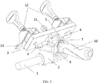
- Figure 1 to Figure 3 render a preferred embodiment of a clamp bench for key duplicating machines, which comprises a fixed component 12, a first rotary component 3, a second rotary component 2 and a slide base 1.
- the fixed component 12 comprises a first fixed component 121 and a second fixed component 122; the first fixed component 121 and the second fixed component 122 are in parallel and opposite to one another.
- the first rotary component 3, the first fixed component 121 and the second fixed component 122 are rigidly connected to the first plane 301 of the first rotary component 3, the first rotary component 3, the first fixed component 121 and the second fixed component 122 are rigidly connected to the first plane 301 of the first rotary component 3, the second rotary component 2 forms a rotary connection with the second plane 302 of the first rotary component 3, and the second plane 302 and the first plane 301 are opposite to one another.
- the first rotary component 3 rotates in the axial direction around the connecting point with the second rotary component 2.
- the slide base 1 forms a rotary connection with the second rotary component 2, the second rotary component 2 rotates in the axial direction around the connecting point with the slide base 1, the axial direction in which the second rotary component 2 rotates is the same as that of the first rotary component 3, and the said second rotary component 2 slides along the slide base 1.
- the master key 13 is the original key
- the key blank is the duplicated key
- the clamp bench of the key duplicating machine is opposite to the key processing bench.
- the clamp bench of the key duplicating machine is equipped with the first rotary component 3 and the second rotary component 2 so that the fixed component 12 clamping the key can simultaneously rotate along two different axial lines in relation to the second rotary component 2 and the slide base 1.
- the user can rotate the first rotary component 3 and the second rotary component 2 to increase the angle of contact of the master key 13 and the key blank 14 with the cutter on the bench, thereby processing the key with bevel tooth.
- the fixed component 12 can slide left and right in relation to the slide base 1, meaning that the fixed component 12 can freely slide in relation to the bench position. After processing one tooth, the user can slide left and right to align other teeth for processing. This will allow the user only to operate horizontal and axial feeding, increasing convenience and improving continuity.
- the first fixed component 121 and the second fixed component 122 comprise an upper clamp 1201, a lower clamp 1202 and a locking mechanism 1203 respectively: the said upper clamp 1201 and the said lower clamp 1202 are opposite to one another, the lower clamp 1202 is rigidly connected to the first plane 301 of the first rotary component 3, and the locking mechanism 1203 is rigidly connected to the upper clamp 1201 and the lower clamp 1202.
- the locking mechanism 1203 is used to control the opening and closing of the upper clamp 1201 and the lower clamp 1202.
- the said master key 13 is placed between the said upper clamp 1201 and the said lower clamp 1202 of the said first fixed component 121, and the said key blank 14 is placed between the said upper clamp 1201 and the said lower clamp 1202 of the said second fixed component 122.
- the said upper clamp 1201 and the said lower clamp 1202 are both provided with a pin hole, and the pin hole on the said upper clamp 1201 is opposite to that on the lower clamp 1202.
- the said locking mechanism 1203 passes through the pin hole of the said clamp and that of the said lower clamp 1202 to lock the said upper clamp 1201 and the said lower clamp 1202, and hold the said master key 13 and the said key blank 14 in place with the said first fixed component 121 and the said second fixed component 122 respectively.
- the clamp bench of the key duplicating machine is opposite to the key processing bench. When a key is duplicated, the original key and the duplicated key will be held in place by the first fixed component 121 and the second fixed component 122 respectively and locked to prevent displacement during the duplicating process.
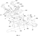
- the second plane 302 of the first rotary component 3 is fitted with a rotary axis 4; the first rotary component 3 rotates in the axial direction around the rotary axis 4.
- the said second rotary component 2 is provided with a first through hole 202, with an inner diameter which is the same as the diameter of the rotary axis 4; the said rotary axis 4 passes through the said first through hole 202 and rotates inside it.
- the rotary axis 4 is semi-cylindrical.
- One side of the plane is rigidly connected to the first rotary component 3.
- the first through hole 202 is arranged around the middle of the rotary axis 4, so the rotary axis 4 can rotate along the inner wall of the first through hole 202 and further drive the first rotary component 3 to rotate in the axial direction.
- the rotary axis 4 is cylindrical, both ends of the axis are rigidly connected to the first rotary component 3, and the first through hole 202 is arranged around the middle of the rotary axis 4, so the rotary axis 4 can rotate along the inner wall of the first through hole 202 and further drive the first rotary component 3 to rotate in the axial direction.
- a control mechanism which comprises a cylindrical pin 6, a control base and a control axis; the cylindrical pin 6 and the control base form a rotary connection, and one end of the control axis and the control base form a rotary connection.
- the cylindrical pin 6 and the second plane 302 of the said first rotary component form a fixed connection, and the other end of the control axis forms a rotary connection with the second rotary component 2.
- the other end of the control axis is rotated to drive the control base to rotate, and driven by the control base, the cylindrical pin will further drive the axial rotation of the first rotary component 3 around the rotary axis 4; the control axis is used to control the movement of the said control base and further drive the axial rotation of the first rotary component around the rotary axis.
- the said cross slide block 7 is provided with a second through hole 701 and a third through hole 702.
- the axial directions of the said second through hole 701 and the said third through hole 702 are perpendicular to one another and are not on the same plane; the axial direction of the said second through hole 701 is parallel to that of the said rotary axis 4.
- the said first rotary component 3 is fitted with a horizontal axial base 5, and both ends of the said horizontal axial base 5 are provided with concentric via holes, that is, a first via hole 501 and a second via hole 502 respectively.
- the cylindrical pin 6 passes through the first via hole 501, the second through hole 701 and the second via hole 502 in turn to form a rotary connection between the said horizontal axial base 5 and the said cross slide block 7, and the said cross slide block 7 slides on the cylindrical pin 6.
- the cross slide block 7 moves in the axial direction of the third through hole 702
- it will drive the second through hole 701 to rotate in the axial direction, which will further drive the cylindrical pin 6 to rotate.
- the first rotary component 3 will accordingly rotate, and at this time, the first rotary component 3 will rotate in two axial directions around the rotary axis 4 and the cylindrical pin 6, thereby performing the overall rotation of the first rotary component 3.
- the control axis is a crank lever 8, and the said crank lever 8 comprises a crank short axis 801, a crank arm 802 and a crank long axis 803: the said crank short axis 801 and the said crank long axis 803 are connected to both ends of the said crank arm 802 and are both perpendicular to the said crank arm 802, the end of the said crank short axis 801 and that of the said crank long axis 803 are opposite in direction, and the crank short axis is inserted into the third through hole 702.
- crank short axis 801 when the crank long axis 803 rotates, the crank short axis 801 will rotate in the axial direction around the crank long axis 803, and when the crank short axis 801 rotates, it will drive the cross slide block 7 to move on the cylindrical pin 6 and can drive the second through hole 701 of the cross slide block 7 to rotate in the axial direction.
- the second rotary component 2 is fitted with a U groove 203: the said cross slide block 7 is arranged in the U groove 203, and rotates in the U groove 203 along the axial direction of the third through hole 702.
- the groove takes a U shape so the cross slide block 7 can slide along the inner wall of the U groove 203, when driven by the crank lever 8.
- the second rotary component 2 is fitted with a crank axial base 9, the said crank axial base 9 is provided with an axis base hole 901, and the crank long axis 803 passes through the axis base hole 901.
- the crank axial base 9 is provided with a bolt via hole and the second rotary component 2 is provided with a corresponding thread hole.
- the crank axial base 9 is rigidly connected to the second rotary component 2 via a bolt.
- the crank long axis 803 passes through the axis base hole 901, and can rotate along the axial line of the axis base hole 901 and hold the crank lever 8 in place to prevent it from sliding out of the third through hole 702 during rotation.
- the first rotary component 3 is fitted with a non-fall locking nut 11
- the crank axial base 9 of the second rotary component 2 is provided with a corresponding thread hole 902
- the non-fall locking nut 11 is screwed into the thread hole 902 to hold the first rotary component 3 and the crank axial base 9 in place.
- the first rotary component 3 does not rotate in relation to the second rotary component 2.
- the non-fall locking nut 11 can be tightened so as to hold the first rotary component 3 and the second rotary component 2 in place. At this time, the first rotary component 3 will not move in relation to the second rotary component 2.
- the user can move the crank long axis 803 up and down so that the first rotary component 3 and the second rotary component 2 will rotate around the slide base 1, and finally, the first rotary component 121, the second fixed component 122, the original key and the duplicated key will rotate around the slide base 1.
- the bottom of the second rotary component 2 is provided with a fourth through hole 201.
- the said slide base 1 is cylindrical, and the inner diameter of the said fourth through hole 201 is the same as the diameter of the said slide base 1.
- the slide base 1 is cylindrical so the second fixed component 2 can slide on the slide base 1, so that the fixed component 12 can freely slide in relation to the bench position. After processing one tooth, the user can slide left and right to align other teeth for processing. This will allow the user only to operate horizontal and axial feeding, increasing convenience and improving continuity.
- the bottom of the second rotary component 2 is fitted with a cylindrical slide block, and one generating line on the outer side of the cylinder is fitted with a connecting sheet.
- One side of the connecting sheet is rigidly connected to one generating line of the cylinder, the opposite side is connected to the second rotary component 2, and the slide base 1 is a C slide groove.
- the slide block crosses the outer side of the slide groove so that the slide block is arranged inside the slide groove, and the connecting sheet is positioned in the gap of the slide groove.
- the connecting piece can sway in the gap of the slide groove, and further drive the slide block to rotate in the axial direction of the slide block inside the slide groove.
- the second rotary component 2 also comprises a handle 10, and the said handle 10 is fitted outside the said crank long axis 803.
- the outer side of the handle 10 is furnished with a concave pattern that can increase the frictional force and help rotate the handle 10 to further drive the rotation of the crank long axis 803.
- the key with bevel tooth is processed as follows: loosen the non-fall locking nut 11 to release the first rotary component 3 and the second rotary component 2.
- the crank short axis 801 crosses the cross slide block 7, and the cross slide block 7 is restricted by two axial lines perpendicular to one another as to the direction of movement.
- the cross slide block 7 will finally rotate back and forth in the direction of the crank short axis 801, slide left and right along the axial line of the cylindrical pin 6, and move up and down in the rotary direction of the handle.
- This will drive the horizontal axial base 5 to rotate up and down around the rotary axis 4 and drive the first rotary component 3 to rotate around the slide base 1, thereby finally causing the first fixed component 121, the second fixed component 122, the original key and the duplicated key to rotate around the slide base 1.
- the user can rotate the handle 10 left and right and pull the handle 10 up and down to make the first fixed component 121, the second fixed component 122, the original key and the duplicated key perform a composite movement, namely, rotate around the slide base 1 and the rotary axis 4, thereby creating a greater angle of contact between the duplicated key and the guide pin sheet and the cutter on the bench.
- the user can press and rotate the handle 10 with one hand to perform composite rotary feeding of the duplicated key along two different axial lines around the rotary axis 4 and the slide base 1, thereby completing the processing of the key with bevel tooth.
- the feeding along the axial line of the duplicated key can be simultaneously performed, thereby enhancing the stability, convenience and continuity of processing.
- the user can tighten the non-fall locking nut 11 to perform single rotary feeding of the duplicated key in the axial direction in relation to the slide base 1, thereby completing the processing of ordinary keys with straight tooth, ensuring universality.
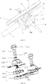
- the fixed component 12 and the first rotary component 3 jointly constitute the clamping mechanism of the key duplicating machine, as shown in Figure 4 to Figure 6 .
- the first fixed component 121 comprises a rotary knob 1211, one end of the rotary knob 1211 is the handle structure 1212, and the other end is provided with a thread hole 1213.
- the clamping mechanism comprises the first rotary component 3 as the base, a spindle 1215, first clamping jaws 1204, a flexible element 1216, second clamping jaws 1208, a thrust bearing 1214 and a rotary knob 1211.
- the base (the first rotary component 3) is fitted with a first embedding structure 303 and an installation hole.
- One end of the spindle 1215 is fitted with an inner thread structure, the installation hole crossing the first rotary component 3 is rigidly connected to the first rotary component 3 via thread connection, and the other end of the spindle 1215 is fitted with an external thread structure 1217.
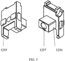
- the two sides of the first clamping jaws 1204 are fitted with a second embedding structure 1205 and a third embedding structure 1206 respectively.
- the third embedding structure 1206 is fitted with a counterbore 1207; the spindle 1215 crosses the counterbore 1207.
- the second embedding structure 1205 is embedded with the first embedding structure 303, the second clamping jaws 1208 are provided with a through hole 1209 and a fourth embedding structure 1210, the second clamping jaws 1208 cross the spindle 1215 via the through hole 1209, and the fourth embedding structure 1210 is embedded with the third embedding structure 1206.
- the flexible element 1216 is arranged around the spindle 1215, the lower end of the flexible element 1216 pushes against the counterbore 1207 of the first clamping jaws 1204, and the upper end of the flexible element pushes against the through hole 1209 of the second clamping jaws 1208.
- the thrust bearing 1214 is arranged around the spindle 1215, the bottom of the thrust bearing 1214 pushes against the second clamping jaws 1208, and the top pushes against the rotary knob 1211.
- One end of the rotary knob 1211 is the handle structure 1212, the other end is provided with the thread hole 1213, and the rotary knob 1211 forms a thread connection with the external thread structure 1217 of the spindle 1215 through the thread hole 1213.
- the first embedding structure 303 is a cross groove
- the installation hole is a round through hole.
- the counterbore 1207 is opposite to the through hole 1209.
- the second embedding structure 1205 and the third embedding structure 1206 are both square concave blocks.
- the fourth embedding structure 1210 is a square groove.
- the flexible element 1216 is a return spring with a restoring force that will keep the first clamping jaws 1204 and the second clamping jaws 1208 away from one another.
- the user when the key is clamped for duplication, the user will put the key on the first clamping jaws 1204, then rotate the rotary knob 1211 with the handle structure 1212; when the rotary knob 1211 rotates, the rotary knob 1211 will move downward as a result of the joint action between the internal thread of the thread hole 1213 and the external thread structure 1217 of the spindle 1215, to press down the second clamping jaws 1208 until they and the first clamping jaws 1204 clamp the key.
- the fourth embedding structure 1210 and the third embedding structure 1206 will embed to limit the clamping jaws and make them clamp the key even more firmly.
- the thrust bearing 1214 is arranged between the rotary knob 1211 and the second clamping jaws 1208; the thrust bearing 1214 is composed of a ball part, an upper cover and a lower cover.
- the rotation of the rotary knob 1211 is actually a rolling friction between the upper cover of the thrust bearing 1214 and the balls, as well as between the lower cover and the balls, to replace the sliding friction between the rotary knob 1211 and the second clamping jaws 1208, thereby reducing the frictional force and preventing the wearing of the rotary knob 1211 and the second clamping jaws 1208.
- the user can rotate the rotary knob 1211 in the opposite direction to move upward, and the second clamping jaws 1208 will also be reset due to the restoring force of the flexible element 1216.
- the clamping mechanism in the clamp bench for the key duplicating machine under this invention uses the directional embedding body as the guiding embedding mechanism between the first clamping jaws and the second clamping jaws. This has the benefits of higher precision, more stable operation, a simple structure and a high level of machining and assembly efficiency.
- the mechanism adds a thrust bearing device, uses the thrust bearing to replace the cushion, and employs the rolling friction between the upper cover of the thrust bearing and the balls, as well as the lower cover and the balls, to replace the sliding friction between the rotary knob and the cushion or between the rotary knob and the second clamping jaws.
- the mechanism delivers good operating performance, causes no abrasion of parts and involves no need to replace components, thereby achieving higher operating performance.
- the specific implementation methods of this invention provide a key duplicating machine, which includes the clamp bench under this invention.
- this invention provides a key duplicating machine, which includes the clamp bench under this invention and a guiding base mechanism.
- the guide base mechanism of the key duplicating machine comprises a guide base foundation 01, a guide base axis 02, a milling cutter guide sheet 03, a regulating nut 04, a cushion 05, a flexible element 06, an end cover 07 and a horizontal regulating bolt 08.
- the guide base foundation 01 is provided with a centre hole; inside the centre hole is the guide base axis 02.
- the milling cutter guide sheet 03 is rigidly connected to the head part of the guide base axis 02 via a thread fastener.
- the middle part of the guide base axis is fitted with an external thread.
- the regulating nut 04 is fitted with an internal thread that matches the external thread, and is fastened on the guide base axis 02 via the thread.
- the cushion 05 is arranged around the guide base axis 02 and fixed between the front-end surface of the guide base foundation 01 and the regulating nut 04.
- the flexible element 06 is arranged between the guide base foundation 01 and the guide base axis 02.
- the end cover 07 is installed in the hole tail part of the guide base foundation 01 via a thread fastener and attached to the guide base foundation 01.
- the horizontal function of the guide base foundation 01 is provided with a thread hole 101, and the regulating nut 08 is installed on the thread hole 101.
- the horizontal regulating bolt 08 is fitted with a round sheet, which is embedded in the groove at the base of the key duplicating machine.
- the tail of the guide base foundation 02 is a waist-like round concave platform, and inside the guide base foundation 01 is a waist-like stair hole that matches the platform.
- the cushion 05 is made of copper or an abrasion-resistant plastic material, and the external surface of the regulating nut 04 is carved with scales.
- the guide base axis 02 passes through the centre hole and is installed on the guide base foundation 01.
- the horizontal regulating bolt 08 is thread connected to the thread hole 101.
- the tail of the guide base foundation 02 is a waist-like round concave platform. Inside the guide base foundation 01 is a waist-like stair hole that matches the platform: this structure will prevent the guide base axis 02 from rotating in the guide base foundation 01 and allow it only to slide along the axial line.
- the milling cutter guide sheet 03 is attached to the head part of the guide base axis 02 via thread fastener and other means.
- the middle part of the guide base axis 02 is fitted with an external thread.
- the regulating nut 04 is fitted with an internal thread that matches it and is fitted on the guide base axis 02 via thread.
- the cushion 05 is arranged around the guide base axis 02 and between the front-end surface of the guide base foundation 01 and the regulating nut 04 to reduce the frictional force during the rotation of the regulating nut 04, and the cushion 05 is made of copper or an abrasion-resistant plastic material.
- the external surface of the regulating nut 04 is carved with scales, which are calculated with the screw pitches of the regulating nut 04 and used to indicate the relationship between the rotary angle and the movement distance of the guide base axis 02.
- the flexible element 06 is arranged between the guide base foundation 01 and the guide base axis 02 to make the regulating nut 04.
- the cushion 05 and the guide base foundation 01 always maintain contact with one another.
- the end cover 07 is installed in the hole tail part of the guide base foundation 01 via thread fastener and other means, and is attached to the guide base foundation 01 to serve as a seal and axial limiter.
- the horizontal direction of the guide base foundation 01 is provided with a thread hole 101, and the horizontal regulating bolt 08 is installed on the thread hole 101.
- the horizontal regulating bolt 08 is fitted with a round sheet, which is embedded in the groove at the base of the key duplicating machine. By rotating the horizontal regulating bolt 08 of the guide base, the user can tune the horizontal direction of the guide base foundation 01 and adjust the horizontal space between the milling cutter guide sheet 03 and the milling cut.
- the user can rotate the regulating nut 04 to make the milling cutter guide sheet 03 of the key duplicating machine retract backward or stretch forward, adjust the locational relationship between the front direction and back direction of the milling cutter and ensure they are aligned.
- the horizontal regulating bolt 08 of the guide base By rotating the horizontal regulating bolt 08 of the guide base, the user can tune the horizontal direction of the guide base foundation 01 and adjust the horizontal space between the milling cutter guide sheet 03 and the milling cut, to ensure consistent positions between them and the key.
- This structure is simple and reliable.
- the nut is arranged at the front end, thereby becoming more convenient and visible.
- the key duplicating machine can better adjust the relative position of the milling cutter, simplify the operation and further increase the processing precision.
Landscapes
- Engineering & Computer Science (AREA)
- Mechanical Engineering (AREA)
- Jigs For Machine Tools (AREA)
- Milling Processes (AREA)
- Clamps And Clips (AREA)
Applications Claiming Priority (1)
| Application Number | Priority Date | Filing Date | Title |
|---|---|---|---|
| CN201910088242.3A CN109648376A (zh) | 2019-01-29 | 2019-01-29 | 钥匙复制机的夹具台 |
Publications (3)
| Publication Number | Publication Date |
|---|---|
| EP3698908A2 true EP3698908A2 (fr) | 2020-08-26 |
| EP3698908A3 EP3698908A3 (fr) | 2020-12-09 |
| EP3698908B1 EP3698908B1 (fr) | 2024-05-22 |
Family
ID=66120885
Family Applications (1)
| Application Number | Title | Priority Date | Filing Date |
|---|---|---|---|
| EP20154238.8A Active EP3698908B1 (fr) | 2019-01-29 | 2020-01-29 | Banc de serrage pour machines à dupliquer les clés et machine à dupliquer les clés |
Country Status (3)
| Country | Link |
|---|---|
| US (1) | US11660687B2 (fr) |
| EP (1) | EP3698908B1 (fr) |
| CN (1) | CN109648376A (fr) |
Families Citing this family (2)
| Publication number | Priority date | Publication date | Assignee | Title |
|---|---|---|---|---|
| CN112629894B (zh) * | 2020-12-08 | 2023-01-24 | 武汉北测检测技术有限责任公司 | 一种补偿缸测试工装及测试方法 |
| CN117884917B (zh) * | 2024-03-15 | 2024-05-14 | 江苏联星机械科技有限公司 | 一种曲轴加工用机床定位装置 |
Citations (3)
| Publication number | Priority date | Publication date | Assignee | Title |
|---|---|---|---|---|
| US20020182022A1 (en) | 2001-06-01 | 2002-12-05 | Ezio Chies | Clamp for a key duplicating machine |
| WO2005039810A1 (fr) | 2003-10-22 | 2005-05-06 | Silca S.P.A. | Pince amelioree conçue pour une machine a tailler les cles |
| US20200001378A1 (en) | 2016-09-13 | 2020-01-02 | The Hillman Group, Inc. | Key duplication machine having pivoting clamp |
Family Cites Families (6)
| Publication number | Priority date | Publication date | Assignee | Title |
|---|---|---|---|---|
| AU658094B1 (en) * | 1994-05-17 | 1995-03-30 | Kuo-Shen Wu | Manual fine adjustment stylus for key duplicating machine |
| TW560377U (en) * | 2003-03-04 | 2003-11-01 | East Of Wu Co Ltd | Improved spring tracer for duplicating machine for punched and laser keys |
| US7153072B2 (en) * | 2004-10-29 | 2006-12-26 | Wu Kuo-Shen | Clamping device for key duplicating machine with dual pivoted joint |
| US7189037B2 (en) * | 2004-10-29 | 2007-03-13 | Wu Kuo-Shen | Versatile adjustable stylus for key duplicating machine |
| TWM405922U (en) * | 2010-12-02 | 2011-06-21 | East Of Wu Co Ltd | Stroke control device for portable-type key machine |
| CN107186512B (zh) * | 2017-07-12 | 2023-09-12 | 深圳数马电子技术有限公司 | 钥匙加工机和钥匙加工机用夹具 |
-
2019
- 2019-01-29 CN CN201910088242.3A patent/CN109648376A/zh active Pending
-
2020
- 2020-01-29 US US16/776,308 patent/US11660687B2/en active Active
- 2020-01-29 EP EP20154238.8A patent/EP3698908B1/fr active Active
Patent Citations (3)
| Publication number | Priority date | Publication date | Assignee | Title |
|---|---|---|---|---|
| US20020182022A1 (en) | 2001-06-01 | 2002-12-05 | Ezio Chies | Clamp for a key duplicating machine |
| WO2005039810A1 (fr) | 2003-10-22 | 2005-05-06 | Silca S.P.A. | Pince amelioree conçue pour une machine a tailler les cles |
| US20200001378A1 (en) | 2016-09-13 | 2020-01-02 | The Hillman Group, Inc. | Key duplication machine having pivoting clamp |
Also Published As
| Publication number | Publication date |
|---|---|
| US11660687B2 (en) | 2023-05-30 |
| EP3698908A3 (fr) | 2020-12-09 |
| CN109648376A (zh) | 2019-04-19 |
| US20200238401A1 (en) | 2020-07-30 |
| EP3698908B1 (fr) | 2024-05-22 |
Similar Documents
| Publication | Publication Date | Title |
|---|---|---|
| EP3698908A2 (fr) | Banc de serrage pour machines à dupliquer les clés et machine à dupliquer les clés | |
| US10464144B2 (en) | Pipe cutting and beveling machine | |
| US20130263712A1 (en) | Miter saw | |
| JPS63214553A (ja) | 固定部に対して可動部を迅速に調節及び固定するリニア装置固定用システム | |
| CN102066030A (zh) | 按钮致动式锁止系统 | |
| US8109494B1 (en) | Workholding apparatus having a movable jaw member | |
| US8573578B1 (en) | Workholding apparatus | |
| EP3427879B1 (fr) | Fixation pour machine à tailler les clés et machine à tailler les clés | |
| US9199319B2 (en) | Clamping device for a machine for duplicating keys | |
| CN106001814B (zh) | 一种火花机电极免夹头定位快装夹具 | |
| US8454004B1 (en) | Workholding apparatus having a movable jaw member | |
| JP2004508207A (ja) | ボーリングヘッド | |
| CN106180813B (zh) | 飞机薄板沉头孔切削装置 | |
| EP2392427B1 (fr) | Table de travail de largeur réglable | |
| US9227303B1 (en) | Workholding apparatus | |
| US9352451B1 (en) | Workholding apparatus | |
| US3037409A (en) | Center adjusting device | |
| CN203390301U (zh) | 切割机 | |
| CN206083924U (zh) | 飞机薄板沉头孔切削装置 | |
| US4735404A (en) | Clamping device for workpieces | |
| CN202087836U (zh) | 双面车削专用机床 | |
| US5267484A (en) | Quill-feed speed handle | |
| US11338375B2 (en) | Portable manual vertical milling key duplicating machine | |
| WO1980000427A1 (fr) | Dispositif de blocage de pieces a usiner | |
| DE2534378C3 (de) | Vorrichtung zur kraftschlussigen Verbindung eines verschwenkbaren Gipsmodell-Tragers mit einer das Motorgehäuse einer Sagemaschine tragenden Grundplatte |
Legal Events
| Date | Code | Title | Description |
|---|---|---|---|
| PUAI | Public reference made under article 153(3) epc to a published international application that has entered the european phase |
Free format text: ORIGINAL CODE: 0009012 |
|
| STAA | Information on the status of an ep patent application or granted ep patent |
Free format text: STATUS: THE APPLICATION HAS BEEN PUBLISHED |
|
| AK | Designated contracting states |
Kind code of ref document: A2 Designated state(s): AL AT BE BG CH CY CZ DE DK EE ES FI FR GB GR HR HU IE IS IT LI LT LU LV MC MK MT NL NO PL PT RO RS SE SI SK SM TR |
|
| AX | Request for extension of the european patent |
Extension state: BA ME |
|
| PUAL | Search report despatched |
Free format text: ORIGINAL CODE: 0009013 |
|
| STAA | Information on the status of an ep patent application or granted ep patent |
Free format text: STATUS: REQUEST FOR EXAMINATION WAS MADE |
|
| AK | Designated contracting states |
Kind code of ref document: A3 Designated state(s): AL AT BE BG CH CY CZ DE DK EE ES FI FR GB GR HR HU IE IS IT LI LT LU LV MC MK MT NL NO PL PT RO RS SE SI SK SM TR |
|
| AX | Request for extension of the european patent |
Extension state: BA ME |
|
| RIC1 | Information provided on ipc code assigned before grant |
Ipc: B23C 3/35 20060101AFI20201103BHEP |
|
| 17P | Request for examination filed |
Effective date: 20201130 |
|
| RBV | Designated contracting states (corrected) |
Designated state(s): AL AT BE BG CH CY CZ DE DK EE ES FI FR GB GR HR HU IE IS IT LI LT LU LV MC MK MT NL NO PL PT RO RS SE SI SK SM TR |
|
| STAA | Information on the status of an ep patent application or granted ep patent |
Free format text: STATUS: EXAMINATION IS IN PROGRESS |
|
| 17Q | First examination report despatched |
Effective date: 20230125 |
|
| GRAP | Despatch of communication of intention to grant a patent |
Free format text: ORIGINAL CODE: EPIDOSNIGR1 |
|
| STAA | Information on the status of an ep patent application or granted ep patent |
Free format text: STATUS: GRANT OF PATENT IS INTENDED |
|
| INTG | Intention to grant announced |
Effective date: 20231212 |
|
| GRAS | Grant fee paid |
Free format text: ORIGINAL CODE: EPIDOSNIGR3 |
|
| GRAA | (expected) grant |
Free format text: ORIGINAL CODE: 0009210 |
|
| STAA | Information on the status of an ep patent application or granted ep patent |
Free format text: STATUS: THE PATENT HAS BEEN GRANTED |
|
| AK | Designated contracting states |
Kind code of ref document: B1 Designated state(s): AL AT BE BG CH CY CZ DE DK EE ES FI FR GB GR HR HU IE IS IT LI LT LU LV MC MK MT NL NO PL PT RO RS SE SI SK SM TR |
|
| REG | Reference to a national code |
Ref country code: GB Ref legal event code: FG4D |