EP3698583B1 - Verteilte mimo-synchronisation - Google Patents
Verteilte mimo-synchronisation Download PDFInfo
- Publication number
- EP3698583B1 EP3698583B1 EP18755471.2A EP18755471A EP3698583B1 EP 3698583 B1 EP3698583 B1 EP 3698583B1 EP 18755471 A EP18755471 A EP 18755471A EP 3698583 B1 EP3698583 B1 EP 3698583B1
- Authority
- EP
- European Patent Office
- Prior art keywords
- group
- time
- access points
- synchronization
- mimo system
- Prior art date
- Legal status (The legal status is an assumption and is not a legal conclusion. Google has not performed a legal analysis and makes no representation as to the accuracy of the status listed.)
- Active
Links
Images


Classifications
-
- H—ELECTRICITY
- H04—ELECTRIC COMMUNICATION TECHNIQUE
- H04W—WIRELESS COMMUNICATION NETWORKS
- H04W56/00—Synchronisation arrangements
- H04W56/001—Synchronization between nodes
- H04W56/002—Mutual synchronization
-
- H—ELECTRICITY
- H04—ELECTRIC COMMUNICATION TECHNIQUE
- H04B—TRANSMISSION
- H04B7/00—Radio transmission systems, i.e. using radiation field
- H04B7/02—Diversity systems; Multi-antenna system, i.e. transmission or reception using multiple antennas
- H04B7/022—Site diversity; Macro-diversity
- H04B7/024—Co-operative use of antennas of several sites, e.g. in co-ordinated multipoint or co-operative multiple-input multiple-output [MIMO] systems
Definitions
- the present disclosure relates to distributed MIMO (Multiple Input Multiple Output) systems, such as distributed massive MIMO systems.
- distributed MIMO Multiple Input Multiple Output
- cellular networks are densified, the inter-cell interference become a major issue and the topology of the network may have to be changed; a conventional cellular architecture with co-located antennas is not necessarily optimal.
- Cell-free massive MIMO also known as “distributed antenna system” or “distributed massive MIMO”
- distributed massive MIMO also known as “distributed antenna system” or “distributed massive MIMO”
- many physically separated access points can be deployed within a conventional cell and there might be no explicit cell boundaries.
- Each user is served by phase-coherent transmission from a subset of such access points, typically the ones that provide a sufficiently high SNR to the user.
- US 2017/0195109 A1 describes the use of an over-the-air synchronization method wherein multiple anchors may be synchronized with each other, in a pairwise manner, and to a common reference clock.
- the anchors may be used e.g. to localize a tag using Time of Arrival measurements.
- a method of operating a distributed MIMO system such as a distribute massive MIMO system.
- the distributed MIMO system is configured to serve a plurality of wireless communication devices.
- the distributed MIMO system comprises a number of access points, each comprising a time circuit configured to keep track of a local time of the access point.
- the method comprises performing an intra-group synchronization procedure for a group of at least three access points, which do not have access to a central time reference.
- the intra-group synchronization procedure comprises, for each access point in the group, transmitting, from that access point, a synchronization signal and obtaining a transmission time indicator indicating a transmission time of that synchronization signal in the local time of that access point.
- the intra-group synchronization procedure comprises receiving, by each of the other access points in the group, the synchronization signal and obtaining reception time indicators indicating reception times, in the local times of the other access points, when the synchronization signal was received by the other access points in the group.
- the intra-group synchronization procedure comprise obtaining, based on the obtained transmission time indicators and reception time indicators, timing adjustment parameters for counteracting time differences between the local times of the access points in the group.
- the method further comprises phase-coherently transmitting a signal to a wireless communication device served by the distributed MIMO system.
- the method may comprise performing the intra-group synchronization procedure for each of a plurality of groups of at least three access points.
- the method may further comprise performing an inter-group synchronization procedure for the plurality of groups.
- the inter-group synchronization procedure may comprise transmitting, from a first group, a synchronization signal and obtaining a transmission time indicator indicating a transmission time of that synchronization signal in a local time of the first group.
- the inter-group synchronization procedure may further comprise receiving, by a second group, the synchronization signal and obtaining a reception time indicator indicating a reception time, in a local time of the second group, when the synchronization signal was received by the second group.
- the inter-group synchronization procedure comprises obtaining, based on the obtained transmission time indicator and reception time indicator, a timing adjustment parameter for counteracting time differences between the local times of the first and the second group.
- the method may comprise transmitting, from a plurality of the access points, a signal to a wireless communication device served by the distributed MIMO system.
- the mutual timing of the transmissions of the signal from the individual access points of the plurality of access points may be controlled based on the above-mentioned timing adjustment parameters.
- a distributed MIMO system comprises a plurality of access points, each comprising a time circuit configured to keep track of a local time of the access point. Furthermore, the distributed MIMO system comprises a control circuit configured to control the MIMO system to perform the method of the first aspect.
- a computer program product comprising computer program code for performing the method of the first aspect when said computer program code is executed by a programmable control circuit of the distributed MIMO system.
- a computer readable medium such as a non-transitory computer-readable medium, storing a computer program product comprising computer program code for performing the method of the first aspect when said computer program code is executed by a programmable control circuit of the distributed MIMO system.
- access point is used in this disclosure.
- term “antenna” or “antenna element” is used in the field of MIMO transmissions with the same meaning as the term “access point” has in this disclosure.
- timing errors between transmissions from different access points to a given wireless communication device can reduce the degree of coherence and, consequently, the obtainable throughput and/or data rate. Due to the physical distance between the different access points, as opposed to the relatively closely spaced antenna elements in an antenna array, the access points typically cannot operate with a common time reference, but will typically each have their own local time reference (or "clock"). Differences between local times in the different access points give rise to the timing errors mentioned above.
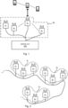
- Fig. 1 is a block diagram of a distributed MIMO system according to an exemplary embodiment.
- the system comprises a plurality of access points A 1 , ..., A K that form a cluster 50 of access points.
- the distributed MIMO system further comprises a central unit 100.
- the central unit 100 can provide backhaul and implement functionalities in higher layer protocols (TCP/IP, PDCP, RLC, MAC), and can also perform a large part of the base-band physical layer processing such as channel coding and decoding, modulation, etc.
- the central unit 100 can also coordinate calculations that are performed relatively seldom; such as determining which access points that should serve which users; ensure that the nodes are properly calibrated; assign pilots to users to be used for channel estimation; make handover decisions to other central units in the vicinity; etc.
- the distributed MIMO system can serve a number N of wireless communication devices (or "wireless devices" for short) u 1 , ..., u N .
- wireless devices include what is generally referred to as a user equipment (UE).
- UE user equipment
- the wireless devices u 1 , ..., u N are depicted in Fig. 1 as mobile phones, but can be any kind of devices with cellular communication capabilities, such as a tablet or laptop computers, machine-type communication (MTC) devices, or similar.
- MTC machine-type communication
- wireless device u k transmits a pilot signal.
- Each of the access points A 1 -A K that receives the pilot signal can utilize it to estimate a channel between itself and the wireless device u k .
- Let g k,m denote the estimated channel between the wireless device u k and the access point A m .
- the access points A 1 -A K can then, jointly, send a signal s k to the wireless device u k using so-called conjugate beamforming, where the signal sent from the access point A m is g k , m ⁇ s k , where g k , m ⁇ denotes the complex conjugate of g k,m .
- Conjugate beamforming is, per se, well known to those skilled in the relevant art and not further discussed herein.
- the scheme described above can facilitate a relatively large portion of the required signal processing to be performed locally in the access points A 1 -A K , since each access point A m can estimate the channel g k,m and derive its conjugate g k,m independently.
- the access points A 1 -A K are involved in the joint transmission to the wireless device u k .
- the access points for which the SNR (signal-to-noise ratio) or SINR (signal-to-interference-and-noise ratio) between the access point and the wireless device u k exceeds a threshold are involved in said joint transmission. If the estimated channels g k,m exactly corresponds to the actual channel, the combined signal received at the wireless device is s ⁇ m
- some exemplary embodiments of the present disclosure can include techniques for synchronizing the access points A 1 , ..., A K , or subsets thereof, in time.
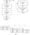
- Fig. 2 illustrates an exemplary arrangement of how access points A i can be grouped into groups G j of at least three access points.
- the groups G j are illustrated as disjoint. However, in other exemplary embodiments, one or more access points A i can belong to more than one group.
- each group G j has exactly three access points A i . However, in some exemplary embodiments, some or all groups G j can have more than three access points A i .
- access points A 1 -A 3 belong to group G 1
- access points A 4 -A 5 belong to group G 2
- access points A 7 -A 9 belong to group G3.
- each access point A i can comprise a time circuit configured to keep track of a local time of the access point A i . This local time can be used in each access point A i for timing events, such as transmissions, from the access point.
- Fig. 3 is a block diagram of an access point A i according to some exemplary embodiments.
- the exemplary access point comprises the above-mentioned time circuit labeled with the reference number 180.
- the exemplary access point can also comprise a transmitter (Tx) circuit 150 and a receiver (Rx) circuit 160.
- Tx transmitter
- Rx receiver
- the Tx circuit 150 and the Rx circuit 160 are shown as connected to a common antenna 185.
- the Tx circuit 150 can comprise a digital-to-analog converter (DAC) for converting a signal to be transmitted from a digital to an analog representation. It may also comprise one or more mixers, filters, power amplifiers, etc. to transform the signal to be transmitted to a physical signal suitable to drive the antenna 185.
- DAC digital-to-analog converter
- the design of Tx circuits is, per se, well known to persons skilled in the relevant art and not discussed herein in any further detail.
- the Rx circuit 160 can comprise an analog-to-digital converter (ADC) for converting received signal from an analog to a digital representation. It can also comprise one or more mixers, filters, low-noise amplifiers (LNAs), etc. to transform a signal received at the antenna 185 to a physical signal suitable to be input to said ADC.
- ADC analog-to-digital converter
- LNAs low-noise amplifiers
- the exemplary access point A i also comprises a digital signal processing (DSP) circuit 170.
- the DSP circuit 170 can be configured to perform conjugate beamforming processing operations locally in the access point A i , on signals to be transmitted via the Tx circuit 150 and/or on signals received via the Rx circuit 160. It can also be configured to derive channel estimates g k,i of the channels between the access point A i and wireless devices Uk.
- Some exemplary embodiments comprise an intra-group synchronization procedure that synchronizes the access points within one of the groups (such as the access points A 1 -A 3 within the group G 1 , etc.) with each other.
- Fig. 3 it is assumed that an absolute, or central, time (or phase) reference is maintained centrally, but the access points A 1 -A 3 are unsynchronized - they do not have access to this time reference.
- the central time reference can be maintained by the central unit 100.
- the Tx circuit 150 and the Rx circuit 160 in each access point A i are unsynchronized. This means that effectively, the Tx circuit 150 and Rx circuit 160 of each access point A i have their own local time references.
- the time circuit 180 can keep track of separate local times for the Tx circuit 150 and the Rx circuit 180.
- the time circuit 180 can keep track of more than one local time, e.g. a separate local time for the Tx circuit 150 and a separate local time for the Rx circuit 160.
- the local time can be viewed as a vector quantity, or tuple, having separate scalar components representing a separate local times for the Tx circuit 150 and the Rx circuit 160).
- the time circuit 180 can keep track of a common local time for the Tx circuit 150 and the Rx circuit 160, but these can nevertheless be unsynchronized due to factors such as signal propagation delays within the Tx circuit 150 and Rx circuit 160, and there may thus effectively be different local times for the Tx circuit 150 and the Rx circuit 160 also in this case.
- the difference in time reference between the Tx circuit 150 and Rx circuit 160 in a given access point A i represents a (uplink-downlink) reciprocity calibration error.
- the difference in, e.g., Tx circuit time reference between any pair of access points represents a synchronization error between these two access point.
- a priori, all reciprocity and synchronization errors are assumed to be unknown.
- the Tx circuit 150 of access point A i has a clock bias of t i from central time, i.e., its local time is zero at central time t i .
- the receiver of access point A i has a clock bias of r i from central time, i.e., its local time is zero at central time r i .
- the access point A 1 transmits a known pulse, below referred to also as a synchronization signal, at its local time zero, this pulse will in central time be transmitted at time t 1 (per definition).
- the access point A 2 transmits the pulse at its local time zero, this pulse will in central time be transmitted at time t 2 (again, per definition).
- the access point A 3 transmits the pulse at its local time zero, this pulse will in central time be transmitted at time t 3 (again, per definition).
- This system has six measurements (i.e., ⁇ ij ) and six unknown variables (i.e., t i and r i ). It is straightforward to show that the matrix is singular such that not all of the variables t 1 , r 1 , t 2 , r 2 , t 3 , r 3 can be obtained from this system.
- some exemplary embodiments of the present disclosure comprise a method of operating the distributed MIMO system.
- the method comprises performing an intra-group synchronization procedure for the group G 1 .
- the intra-group synchronization method and/or procedure which is illustrated in Fig. 4 with a flow chart, comprises, for each access point A i in the group Gi:
- step T 1 can be carried out first, then step T 2 , then step T 3 .
- step T 3 can be carried out in any order.
- step T 1 can be carried out first, then step T 2 , then step T 3 .
- any other order can be used as well.
- the transmission time indicators and reception time indicators can include sufficient information to enable determination of the reciprocity errors and the synchronization errors.
- the transmission time indicators and the reception time indicators can be used as a basis for obtaining timing adjustment parameters for counteracting time differences between the local times of the access points Ai-A 3 in the group G 1 .
- the timing adjustment parameters can be numbers indicating said time differences, expressed in a suitable unit. Counteracting the time differences can be done in several different ways. One exemplary technique is to adjust the local times within the access points A 1 -A 3 such that these are essentially the same.
- Another exemplary technique is to leave the local times as they are, but adjust the transmission times (in local times) of data transmissions from the access points A 1 -A 3 such that these transmissions are coherent.
- the access points A 1 -A 3 in the group G 1 can be considered to have a common local time after the intra-group synchronization procedure. Below, this is referred to as the local time of G 1 .
- the local time of G 1 can be the local time that is kept track of by the time circuit 180 in one of the access points A 1 -A 3 .
- the bias of the local time of G 1 is referred to as b 1 below. That is, the local time of G 1 is zero at central time b 1 .
- the method of operating the distributed MIMO system comprises performing the intra-group synchronization procedure for each of a plurality of groups (such as G 1 , G 2 , G 3 ) of at least three access points (such as A 1 -A 3 , A 4 -A 6 , A 7 -A 9 ).
- the access points A i in the group G j can be considered to have a common local time after the intra-group synchronization procedure.
- this is referred to as the local time of G j .
- the local time of G 1 can be the local time that is kept track of by the time circuit 180 in one of the access points A i in the group G j .
- the bias of the local time of G j is referred to as &, below. That is, the local time of G j is zero at central time b j .
- Fig. 5 shows a flowchart for an exemplary embodiment a synchronization procedure 190, which can be included in embodiments of the method and/or procedure of operating the distributed MIMO system. Operation of the synchronization procedure is started in step 200. In step 210, an intra-group synchronization procedure, e.g. as described above, is performed for one or more groups G j . As illustrated in Fig. 5 , some exemplary embodiments of the synchronization procedure can comprise performing an inter-group synchronization procedure in step 220, i.e., synchronizing the access points of two or more different groups.
- Fig. 6 is a flowchart of a method and/or procedure of operating the distributed MIMO system according to an exemplary embodiment. It includes the synchronization procedure 190 described above. As indicated in Fig. 6 , the exemplary method and/or procedure can also comprise step 240 of transmitting, from a plurality of the access points A i , a signal to a wireless communication device u k (or to multiple such communication devices) served by the distributed MIMO system. The mutual timing of the transmissions of the signal from the individual access points A i of the plurality of access points can be controlled based on timing adjustment parameters obtained in the synchronization procedure 190. Thereby, coherent transmission from the different access points A i is facilitated.
- inter-group synchronization step 220 Exemplary embodiments of the inter-group synchronization step 220 are discussed below in some more detail.
- first inter-group synchronization between group G 1 and group G 2 In this context, it is assumed that both group G 1 and group G 2 have been subject to intra-group synchronization. Thus, the reciprocity errors and synchronization errors within each of the groups are considered to be zero.
- the access points A 1 -A 3 share a common local time, which is the local time of G 1 .
- the access points A 4 -A 6 share a common local time, which is the local time of G 2 .
- the group G 1 transmits a known pulse, below referred to also as a synchronization signal, at its local time zero, this pulse will in central time be transmitted at time b 1 (per definition).
- the transmission from the group G 1 can be a transmission from any one of the access points A 1 -A 3 , or a coherent transmission from any combination of the access points A 1 -A 3 .
- the reception by the group G 2 can be a reception by any one of the access points A 4 -A 6 , or a coherent reception by any combination of the access points A 4 -A 6 .
- d 12 represents the synchronization error between group G 1 and group G 2 .
- Transmission time zero was selected for illustration. If the pulse is transmitted at a given time ⁇ G1 in the local time of G1, it will instead be received at time d 12 + ⁇ G1 in the local time of G 2 .
- the synchronization error d 12 can then readily be derived by subtracting ⁇ G1 from this reception time.
- Fig. 7 illustrates a flow chart for some exemplary embodiments of the inter-group synchronization procedure between the group G 1 and the group G 2 .
- the same flowchart can be generalized to a inter-group synchronization procedure between two arbitrary groups G i and G j by simply replacing the index 1 with i and the index 2 with j .
- the inter-group synchronization procedure illustrated in Fig. 7 comprises
- the transmission time indicator obtained in step OG 1 and the reception time indicator obtained in step OG 2 can be used as a basis for obtaining a timing adjustment parameter for counteracting time differences between the local times of the group G 1 and the group G 2 .
- the timing adjustment parameter can be a number indicating said time difference, expressed in a suitable unit. It may, for instance, be the synchronization error d 12 mentioned above.
- This timing adjustment parameter can be used in step 240, in combination with the timing adjustment parameters from the intra-group synchronization in step 210, to control the mutual timing of the transmissions from the individual access points to facilitate coherent transmissions.
- the inter-group synchronization procedure can be extended to N ⁇ 3 groups G 1 -G N in several different ways.
- group G 2 is first synchronized with group G 1 as above. Then, group G 3 can be synchronized with group G 2 in the same way. After that, group G 4 can be synchronized with group G 3 in the same way, etc.
- a reception time indicator indicating a reception time, in the local time of that group G j , when the synchronization signal was received by that group G j .
- the distributed MIMO system can comprise a control circuit configured to control the MIMO system to perform the method disclosed herein.
- the control circuit can be or be comprised in the central unit 100.
- the control circuit can be distributed within the distributed MIMO system, e.g. partly residing within the central unit 100 and partly within the access points A 1 -A K , such as within the DSP circuits 170 within one or more of the access points A 1 -AP K .
- control circuit 310 can be implemented as a dedicated application-specific hardware unit.
- said control circuit 310, or parts thereof, can be implemented with programmable and/or configurable hardware units, such as but not limited to one or more field-programmable gate arrays (FPGAs), processors, or microcontrollers.
- FPGAs field-programmable gate arrays
- the control circuit 310 can be a programmable control circuit 310.
- embodiments of the present disclosure can be embedded in a computer program product, which enables implementation of the method and functions described herein.
- a computer program product comprising computer program code that configures the control circuit 310 to perform any of the functions or method embodiments herein when said computer program code is executed by the programmable control circuit 310.
- the control circuit 310 can perform the method steps or functions directly, the control circuit 310 can cause other circuits or units to perform the method steps or functions, or a combination thereof.
- the computer program product can be stored on a computer-readable medium, such as a non-transitory computer-readable medium 300, as illustrated in Fig. 8 , from which the program code can be loaded and executed by said programmable control circuit 310.
Landscapes
- Engineering & Computer Science (AREA)
- Computer Networks & Wireless Communication (AREA)
- Signal Processing (AREA)
- Radio Transmission System (AREA)
- Mobile Radio Communication Systems (AREA)
Claims (9)
- Verfahren zum Betreiben eines verteilten MIMO-Systems, wobei das verteilte MIMO-System dazu konfiguriert ist, eine oder mehrere drahtlose Kommunikationsvorrichtungen (u1, ..., u N ) zu bedienen, und Folgendes umfasst:eine Vielzahl von Zugangspunkten (A1, ..., A K ), von denen jeder eine Zeitschaltung (180) umfasst, die dazu konfiguriert ist, eine Ortszeit des Zugangspunkts (A1, ..., A K ) zu verfolgen;und wobei das Verfahren Durchführen (210) einer gruppeninternen Synchronisierungsprozedur für eine Gruppe (G1) von mindestens drei Zugangspunkten (A1-A3) umfasst, die keinen Zugang zu einer zentralen Zeitreferenz haben, wobei die gruppeninterne Synchronisierungsprozedur Folgendes umfasst:für jeden Zugangspunkt (A i ) in der Gruppe (G1):Übertragen (T i ) eines Synchronisierungssignals von diesem Zugangspunkt (A i ) aus;Erhalten (O i ) eines Übertragungszeitindikators, der eine Übertragungszeit dieses Synchronisationssignals in der Ortszeit dieses Zugangspunkts (A i ) angibt;Empfangen (R im , R in ) des Synchronisationssignals durch jeden der anderen Zugangspunkte (A m , A n ) in der Gruppe; undErhalten (O im , O in ) von Empfangszeitindikatoren, die Empfangszeiten in den Ortszeiten der anderen Zugangspunkte (A m , A n ) angeben, zu denen das Synchronisierungssignal von den anderen Zugangspunkten (A m , A n ) in der Gruppe empfangen wurde; undErhalten von Zeitanpassungsparametern zum Ausgleichen von Zeitunterschieden zwischen den Ortszeiten der Zugangspunkte (A1-A3) in der Gruppe (G1) basierend auf den erhaltenen Übertragungszeitindikatoren und Empfangszeitindikatoren;wobei das Verfahren weiter phasenkohärentes Übertragen (240) eines Signals an eine drahtlose Kommunikationsvorrichtung (uk) umfasst, die vom verteilten MIMO-System bedient wird.
- Verfahren nach Anspruch 1, umfassend:
Durchführen der gruppeninternen Synchronisierungsprozedur für jede einer Vielzahl von Gruppen (G1, G2, G3) aus mindestens drei Zugangspunkten (A1-A3, A4-A6, A7-A9), die keinen Zugang zu einer zentralen Zeitreferenz haben. - Verfahren nach Anspruch 2, umfassend:
Durchführen (220) einer gruppeninternen Synchronisierungsprozedur für die Vielzahl von Gruppen. - Verfahren nach Anspruch 3, wobei die gruppeninterne Synchronisierungsprozedur Folgendes umfasst:Übertragen (TG1) eines Synchronisationssignals von einer ersten Gruppe (G1) aus;Erhalten (OG1) eines Übertragungszeitindikators, der eine Übertragungszeit dieses Synchronisationssignals in einer Ortszeit der ersten Gruppe (G1) angibt;Empfangen (RG12) des Synchronisationssignals durch eine zweite Gruppe (G2); undErhalten (OG12) eines Empfangszeitindikators, der eine Empfangszeit in einer Ortszeit der zweiten Gruppe (G2) angibt, zu der das Synchronisationssignal von der zweiten Gruppe (G2) empfangen wurde.
- Verfahren nach Anspruch 4, wobei die gruppeninterne Synchronisierungsprozedur Folgendes umfasst:
Erhalten, basierend auf dem erhaltenen Übertragungszeitindikator und Empfangszeitindikator, eines Zeitanpassungsparameters zum Ausgleichen von Zeitunterschieden zwischen den Ortszeiten der ersten und der zweiten Gruppe (G1, G2). - Verfahren nach Anspruch 1, wobei die gegenseitige zeitliche Abstimmung der Übertragungen des Signals von den einzelnen Zugangspunkten (Aj) der Vielzahl von Zugangspunkten basierend auf den Zeitanpassungsparametern gesteuert wird.
- Verteiltes MIMO-System, umfassendeine Vielzahl von Zugangspunkten (A1, ..., A K ), die jeweils eine Zeitschaltung (180) umfassen, die dazu konfiguriert ist, eine Ortszeit des Zugangspunkts (A1, ..., A K ) zu verfolgen, die jedoch keinen Zugang zu einer zentralen Zeitreferenz haben; undeine Steuerschaltung (100, 310), die dazu konfiguriert ist, das MIMO-System zu steuern, um das Verfahren nach einem vorstehenden Anspruch durchzuführen.
- Computerprogrammprodukt, das Computerprogrammcode zum Durchführen des Verfahrens nach einem der Ansprüche 1-6 umfasst, wenn der Computerprogrammcode von einer programmierbaren Steuerschaltung (310) des verteilten MIMO-Systems ausgeführt wird.
- Computerlesbares Medium (300), das ein Computerprogrammprodukt speichert, das Computerprogrammcode zum Durchführen des Verfahrens nach einem der Ansprüche 1-6 umfasst, wenn der Computerprogrammcode von einer programmierbaren Steuerschaltung (310) des verteilten MIMO-Systems ausgeführt wird.
Applications Claiming Priority (2)
| Application Number | Priority Date | Filing Date | Title |
|---|---|---|---|
| US201762573280P | 2017-10-17 | 2017-10-17 | |
| PCT/EP2018/072130 WO2019076513A1 (en) | 2017-10-17 | 2018-08-15 | DISTRIBUTED MIMO SYNCHRONIZATION |
Publications (2)
| Publication Number | Publication Date |
|---|---|
| EP3698583A1 EP3698583A1 (de) | 2020-08-26 |
| EP3698583B1 true EP3698583B1 (de) | 2024-12-04 |
Family
ID=63209428
Family Applications (1)
| Application Number | Title | Priority Date | Filing Date |
|---|---|---|---|
| EP18755471.2A Active EP3698583B1 (de) | 2017-10-17 | 2018-08-15 | Verteilte mimo-synchronisation |
Country Status (3)
| Country | Link |
|---|---|
| US (1) | US11564188B2 (de) |
| EP (1) | EP3698583B1 (de) |
| WO (1) | WO2019076513A1 (de) |
Families Citing this family (2)
| Publication number | Priority date | Publication date | Assignee | Title |
|---|---|---|---|---|
| US12382406B2 (en) | 2020-03-02 | 2025-08-05 | Telefonaktiebolaget Lm Ericsson (Publ) | Over the air antenna synchronization in wireless communication network |
| US20240171993A1 (en) * | 2021-03-30 | 2024-05-23 | Sony Group Corporation | Wireless communication device and method |
Family Cites Families (90)
| Publication number | Priority date | Publication date | Assignee | Title |
|---|---|---|---|---|
| US1246229A (en) | 1917-05-10 | 1917-11-13 | Robert H Brauch | Creel. |
| US4812855A (en) | 1985-09-30 | 1989-03-14 | The Boeing Company | Dipole antenna with parasitic elements |
| US5602834A (en) | 1990-12-07 | 1997-02-11 | Qualcomm Incorporated | Linear coverage area antenna system for a CDMA communication system |
| US5513176A (en) | 1990-12-07 | 1996-04-30 | Qualcomm Incorporated | Dual distributed antenna system |
| GB2331630B (en) | 1997-11-20 | 2001-12-05 | Nec Technologies | Retractable antenna for a mobile telephone |
| US6362906B1 (en) | 1998-07-28 | 2002-03-26 | Raytheon Company | Flexible optical RF receiver |
| EP1028483B1 (de) | 1999-02-10 | 2006-09-27 | AMC Centurion AB | Verfahren und Vorrichtung zur Herstellung einer Rolle von Antennenelementen und zur Ausgabe derartiger Antennenelemente |
| AU7422401A (en) | 2000-06-13 | 2001-12-24 | Red-M (Communications) Limited | Distributed bluetooth communications network |
| US6950414B1 (en) | 2000-10-17 | 2005-09-27 | Ericsson Inc. | Cable carrying communications data and timing data to radio heads |
| US6975877B1 (en) * | 2001-10-17 | 2005-12-13 | Cisco Technology, Inc. | System and method for synchronizing clock dividers in a wireless network |
| US8208364B2 (en) | 2002-10-25 | 2012-06-26 | Qualcomm Incorporated | MIMO system with multiple spatial multiplexing modes |
| US7047028B2 (en) | 2002-11-15 | 2006-05-16 | Telefonaktiebolaget Lm Ericsson (Publ) | Optical fiber coupling configurations for a main-remote radio base station and a hybrid radio base station |
| US9143305B2 (en) | 2005-03-17 | 2015-09-22 | Qualcomm Incorporated | Pilot signal transmission for an orthogonal frequency division wireless communication system |
| US7876764B2 (en) | 2005-10-11 | 2011-01-25 | Cisco Technology, Inc. | Multiple aggregation protocol sessions in a daisy chain network |
| JP4696842B2 (ja) | 2005-10-21 | 2011-06-08 | ソニー株式会社 | 無線通信装置、アンテナ・キャリブレーション方法、並びにコンピュータ・プログラム |
| ATE508604T1 (de) | 2005-12-13 | 2011-05-15 | Panasonic Corp | Wahl eines zugangsknotens zum senden von empfangsbestätigungen an ein drahtloses netzwerk |
| US7372424B2 (en) | 2006-02-13 | 2008-05-13 | Itt Manufacturing Enterprises, Inc. | High power, polarization-diverse cloverleaf phased array |
| US8472767B2 (en) | 2006-05-19 | 2013-06-25 | Corning Cable Systems Llc | Fiber optic cable and fiber optic cable assembly for wireless access |
| US8344949B2 (en) * | 2008-03-31 | 2013-01-01 | Golba Llc | Wireless positioning approach using time-delay of signals with a known transmission pattern |
| KR20140091616A (ko) | 2006-12-26 | 2014-07-21 | 달리 시스템즈 씨오. 엘티디. | 다중 채널 광대역 통신 시스템에서의 기저 대역 전치 왜곡 선형화를 위한 방법 및 시스템 |
| US7417592B1 (en) | 2007-02-27 | 2008-08-26 | Cheng Uei Precision Industry Co., Ltd. | Portable audio wireless communication device |
| JP4485547B2 (ja) | 2007-06-21 | 2010-06-23 | 株式会社エヌ・ティ・ティ・ドコモ | 移動局、および、移動局における送信電力制御方法 |
| US8374163B2 (en) * | 2007-11-09 | 2013-02-12 | Qualcomm Incorporated | Synchronization of wireless nodes |
| US8077614B2 (en) * | 2007-12-05 | 2011-12-13 | At&T Intellectual Property I, L.P. | Synchronizing wireless local area network access points |
| US8203483B2 (en) | 2008-03-13 | 2012-06-19 | Cubic Corporation | Digital beamforming antenna and datalink array |
| US8660153B2 (en) * | 2008-09-17 | 2014-02-25 | Qualcomm Incorporated | Methods and apparatus for frame number synchronization in wireless communication networks |
| JP5608656B2 (ja) | 2008-09-26 | 2014-10-15 | テレフオンアクチーボラゲット エル エム エリクソン(パブル) | アクセス・ノードの上りリンク協力のための技法 |
| EP2214261A1 (de) | 2009-01-30 | 2010-08-04 | Alcatel Lucent | Strahlenbildendes Antennensystem auf einem flexiblen Kunststofffilm |
| JP5480916B2 (ja) | 2009-02-03 | 2014-04-23 | コーニング ケーブル システムズ リミテッド ライアビリティ カンパニー | 光ファイバベースの分散型アンテナシステム、構成要素、及びその較正のための関連の方法 |
| US20100208777A1 (en) | 2009-02-17 | 2010-08-19 | Adc Telecommunications, Inc. | Distributed antenna system using gigabit ethernet physical layer device |
| US8249049B2 (en) * | 2009-03-17 | 2012-08-21 | Cisco Technology, Inc. | Clock synchronization |
| US8275265B2 (en) | 2010-02-15 | 2012-09-25 | Corning Cable Systems Llc | Dynamic cell bonding (DCB) for radio-over-fiber (RoF)-based networks and communication systems and related methods |
| US8279897B2 (en) * | 2010-03-02 | 2012-10-02 | Hewlett-Packard Development Company, L.P. | Synchronization in a wireless node |
| US8731354B2 (en) | 2010-07-30 | 2014-05-20 | Corning Cable Systems Llc | Array cable assemblies |
| US20120120874A1 (en) * | 2010-11-15 | 2012-05-17 | Decawave Limited | Wireless access point clock synchronization system |
| JP5690842B2 (ja) | 2010-11-19 | 2015-03-25 | 株式会社フジクラ | アンテナ一体型ハーネス |
| SG189459A1 (en) | 2010-11-29 | 2013-05-31 | Ericsson Telefon Ab L M | An antenna arrangement |
| EP2692069B1 (de) | 2011-03-31 | 2019-08-07 | Huawei Technologies Co., Ltd. | Verfahren in einem drahtlosen kommunikationssystem |
| US8462069B2 (en) | 2011-04-18 | 2013-06-11 | Harris Corporation | Accessory system with integrated multiband antenna |
| US9008677B2 (en) | 2011-06-08 | 2015-04-14 | Qualcomm Incorporated | Communication devices for multiple group communications |
| US8669916B2 (en) | 2011-08-26 | 2014-03-11 | Rogers Communications Inc. | Vertically interleaved distributed antenna system |
| US20130285879A1 (en) | 2012-04-30 | 2013-10-31 | Theodore J. WHEELER | Antenna |
| US9288777B2 (en) * | 2012-05-11 | 2016-03-15 | Apple Inc. | Methods and apparatus for synchronizing clock signals in a wireless system |
| CN102685673B (zh) | 2012-05-18 | 2015-07-29 | 奇点新源国际技术开发(北京)有限公司 | 一种线缆系统 |
| US20150162751A1 (en) | 2013-05-10 | 2015-06-11 | DvineWave Inc. | Wireless charging of clothing and smart fabrics |
| JP5729833B2 (ja) | 2012-07-09 | 2015-06-03 | 日本電信電話株式会社 | 基地局装置、無線通信方法、及び無線通信システム |
| US9154222B2 (en) | 2012-07-31 | 2015-10-06 | Corning Optical Communications LLC | Cooling system control in distributed antenna systems |
| FI125462B (en) | 2013-01-29 | 2015-10-15 | Inverpolis Oy | A method and system for using a phased antenna field |
| US20140211779A1 (en) * | 2013-01-31 | 2014-07-31 | University Of Southern California | Scalable synchronization for distributed multiuser mimo |
| US20140269645A1 (en) * | 2013-03-13 | 2014-09-18 | Qualcomm Incorporated | Wireless access point synchronization |
| US20140362840A1 (en) * | 2013-06-07 | 2014-12-11 | Broadcom Corporation | Inter-AP coordination and synchronization within wireless communications |
| US9226184B2 (en) | 2013-06-27 | 2015-12-29 | Cisco Technology, Inc. | Estimating and utilizing client receive interference cancellation capability in multi-user transmissions |
| CN104283594B (zh) | 2013-07-03 | 2017-11-28 | 华为技术有限公司 | 一种预编码方法及设备 |
| US9655072B2 (en) * | 2013-11-08 | 2017-05-16 | Qualcomm, Incorporated | Systems, apparatus and methods for synchronizing a global time reference for access points over the air |
| CN105007126B (zh) | 2014-04-23 | 2017-09-29 | 电信科学技术研究院 | 一种信道状态信息测量的方法、系统及设备 |
| US9583814B2 (en) | 2014-09-08 | 2017-02-28 | Illinois Tool Works Inc. | System and method for an antenna on a cable |
| US9769020B2 (en) | 2014-10-21 | 2017-09-19 | At&T Intellectual Property I, L.P. | Method and apparatus for responding to events affecting communications in a communication network |
| JP6386672B2 (ja) | 2014-12-11 | 2018-09-05 | 華為技術有限公司Huawei Technologies Co.,Ltd. | データ処理方法、装置、及びデバイス |
| WO2016115546A1 (en) | 2015-01-16 | 2016-07-21 | Ping Liang | Beamforming in a mu-mimo wireless communication system |
| CN107431534B (zh) * | 2015-02-13 | 2020-09-08 | 英国电讯有限公司 | 操作通信网络的方法、基站、有形数据载体、终端 |
| KR101608056B1 (ko) | 2015-03-20 | 2016-04-11 | 광주과학기술원 | 전이중 와이파이 네트워크에서의 매체접근 제어 방법 |
| US20160323925A1 (en) * | 2015-04-30 | 2016-11-03 | Nokia Technologies Oy | Method, apparatus, and computer program product for inter-ap communication in neighbor awareness networking environment |
| US10154493B2 (en) | 2015-06-03 | 2018-12-11 | At&T Intellectual Property I, L.P. | Network termination and methods for use therewith |
| CN107683580B (zh) | 2015-06-28 | 2020-11-24 | 梁平 | 在多用户多入多出系统中实现频率资源分配的方法 |
| US10051587B2 (en) * | 2015-07-09 | 2018-08-14 | Google Llc | System for network discovery and synchronization |
| US9749053B2 (en) | 2015-07-23 | 2017-08-29 | At&T Intellectual Property I, L.P. | Node device, repeater and methods for use therewith |
| CN106571866B (zh) | 2015-10-10 | 2019-09-17 | 上海诺基亚贝尔股份有限公司 | 无线接入系统 |
| US10608734B2 (en) | 2015-10-22 | 2020-03-31 | Phluido, Inc. | Virtualization and orchestration of a radio access network |
| CN106936552B (zh) | 2015-12-30 | 2020-04-03 | 上海无线通信研究中心 | 大规模mimo系统中上行导频序列分配方法及基站 |
| US9954669B2 (en) * | 2016-01-06 | 2018-04-24 | Alcatel-Lucent Usa Inc. | Method and apparatus for over-the-air anchor-anchor synchronization |
| US20170271745A1 (en) | 2016-03-17 | 2017-09-21 | Tyco Electronics Corporation | Antenna cover having a thermal barrier |
| US10129841B2 (en) * | 2016-04-07 | 2018-11-13 | Intel IP Corporation | Apparatus, system and method of communicating timing synchronization information |
| US9860075B1 (en) | 2016-08-26 | 2018-01-02 | At&T Intellectual Property I, L.P. | Method and communication node for broadband distribution |
| CN107872293B (zh) | 2016-09-28 | 2023-04-07 | 华为技术有限公司 | 信号传输方法和装置 |
| KR102641746B1 (ko) | 2016-10-18 | 2024-02-29 | 삼성전자주식회사 | 대규모 안테나를 이용하는 무선 통신 시스템에서 프리코딩을 수행하기 위한 장치 및 방법 |
| CA3040521A1 (en) | 2016-10-27 | 2018-05-03 | Rearden, Llc | Systems and methods for distributing radioheads |
| CN108377559B (zh) | 2016-11-04 | 2021-03-30 | 华为技术有限公司 | 基于波束的多连接通信方法、终端设备及网络设备 |
| JP6898448B2 (ja) | 2016-12-09 | 2021-07-07 | テレフオンアクチーボラゲット エルエム エリクソン(パブル) | 分散マッシブmimoのための改良されたアンテナ装置 |
| WO2018116096A1 (en) | 2016-12-19 | 2018-06-28 | Netsia, Inc. | System and method for programmable virtualization of co-channel heterogeneous networks utilizing dual connectivity |
| US9960849B1 (en) | 2016-12-22 | 2018-05-01 | Intel Corporation | Channelization for dispersion limited waveguide communication channels |
| US10079668B2 (en) | 2016-12-22 | 2018-09-18 | Intel Corporation | Waveguide communication with increased link data rate |
| CN108418614B (zh) | 2017-02-10 | 2021-04-09 | 上海诺基亚贝尔股份有限公司 | 用于非线性预编码的通信方法和设备 |
| JP2018182660A (ja) | 2017-04-20 | 2018-11-15 | 日本電信電話株式会社 | 無線通信装置及び再送制御方法 |
| WO2019053745A1 (en) | 2017-09-14 | 2019-03-21 | Shridhar Bam Anupam | PATIENT TRANSPORT DEVICE FOR PROVIDING LIFTING, IMMOBILIZATION AND TRANSPORT IN THE SAME DEVICE |
| GB201714992D0 (en) | 2017-09-18 | 2017-11-01 | Cambridge Entpr Ltd | RFID systems |
| US10602466B2 (en) * | 2017-11-09 | 2020-03-24 | Qualcomm Incorporated | Multi-basic service set uplink time alignment |
| WO2019101290A1 (en) | 2017-11-21 | 2019-05-31 | Telefonaktiebolaget Lm Ericsson (Publ) | Improved antenna arrangement for distributed massive mimo |
| EP3725001B1 (de) | 2018-02-02 | 2022-09-14 | Viasat, Inc. | Funkfrequenz-loopback für sendeempfänger |
| KR102322380B1 (ko) | 2018-02-14 | 2021-11-10 | 주식회사 케이티 | 릴레이 노드에서 상향링크 사용자 데이터를 처리하는 방법 및 그 장치 |
| WO2019240808A1 (en) | 2018-06-15 | 2019-12-19 | Nokia Technologies Oy | Backhaul scheduling |
-
2018
- 2018-08-15 EP EP18755471.2A patent/EP3698583B1/de active Active
- 2018-08-15 US US16/649,768 patent/US11564188B2/en active Active
- 2018-08-15 WO PCT/EP2018/072130 patent/WO2019076513A1/en not_active Ceased
Also Published As
| Publication number | Publication date |
|---|---|
| EP3698583A1 (de) | 2020-08-26 |
| US11564188B2 (en) | 2023-01-24 |
| US20200322907A1 (en) | 2020-10-08 |
| WO2019076513A1 (en) | 2019-04-25 |
Similar Documents
| Publication | Publication Date | Title |
|---|---|---|
| AU2020314455B2 (en) | Time-division duplex multiple-input multiple-output calibration | |
| CN111837354B (zh) | 辅小区的小区激活的方法及其电子设备 | |
| CN107210811B (zh) | 用于分布式大规模mimo(dm-mimo)的方法 | |
| EP3565134A1 (de) | Antennenkorrekturverfahren und -vorrichtung | |
| WO2015190648A1 (en) | Beam scanning method for hybrid beamforming in wireless communication system and apparatus therefor | |
| EP4233226A1 (de) | Signalisierungsportinformationen | |
| WO2018028470A1 (zh) | 一种波束管理方法和相关设备 | |
| EP3698583B1 (de) | Verteilte mimo-synchronisation | |
| CN103457676B (zh) | 宏-毫微微小区间干扰消除 | |
| CN111953394B (zh) | 多天线系统及其信道校正方法 | |
| WO2022069184A1 (en) | Dynamic antenna array angular phase deviation compensation for broad beam positioning | |
| CN102934371A (zh) | 用于减少多用户无线系统中的小区间干扰的多天线方法和装置 | |
| US20250175921A1 (en) | High Resolution Timing Advance Estimation Based on PRACH | |
| US20220086787A1 (en) | Wireless device, network node and methods performed therein for time of arrival estimation | |
| WO2024228929A1 (en) | Methods, apparatuses and systems for intelligent reflection surface installed user equipment channel estimation | |
| WO2023136838A1 (en) | Complexity reduction for open radio access network radio unit uplink receiver | |
| WO2025043592A1 (en) | Direction alias elimination for hybrid beamforming in cellular antenna arrays | |
| US12513638B2 (en) | Systems and methods for enhanced multiple transmission and reception point communications | |
| Luo et al. | A new reciprocity calibration method for massive MIMO systems | |
| TW202535043A (zh) | 針對收發點間的時序偏移補償 | |
| WO2026033204A1 (en) | Methods, communications devices, and radio access nodes for calibration of coherent joint transmissions | |
| WO2024211125A1 (en) | Methods, apparatuses and systems for intelligent reflection surface installed user equipment channel estimation | |
| WO2024233064A1 (en) | Methods, apparatuses and systems for intelligent reflection surface installed user equipment channel quality index determination | |
| WO2026033216A1 (en) | Methods, communications devices, and nodes | |
| KR20250073457A (ko) | 캐리어 집성을 이용한 포지셔닝 측정 정확도 향상 |
Legal Events
| Date | Code | Title | Description |
|---|---|---|---|
| STAA | Information on the status of an ep patent application or granted ep patent |
Free format text: STATUS: UNKNOWN |
|
| STAA | Information on the status of an ep patent application or granted ep patent |
Free format text: STATUS: THE INTERNATIONAL PUBLICATION HAS BEEN MADE |
|
| PUAI | Public reference made under article 153(3) epc to a published international application that has entered the european phase |
Free format text: ORIGINAL CODE: 0009012 |
|
| STAA | Information on the status of an ep patent application or granted ep patent |
Free format text: STATUS: REQUEST FOR EXAMINATION WAS MADE |
|
| 17P | Request for examination filed |
Effective date: 20200416 |
|
| AK | Designated contracting states |
Kind code of ref document: A1 Designated state(s): AL AT BE BG CH CY CZ DE DK EE ES FI FR GB GR HR HU IE IS IT LI LT LU LV MC MK MT NL NO PL PT RO RS SE SI SK SM TR |
|
| AX | Request for extension of the european patent |
Extension state: BA ME |
|
| DAV | Request for validation of the european patent (deleted) | ||
| DAX | Request for extension of the european patent (deleted) | ||
| STAA | Information on the status of an ep patent application or granted ep patent |
Free format text: STATUS: EXAMINATION IS IN PROGRESS |
|
| 17Q | First examination report despatched |
Effective date: 20211020 |
|
| GRAP | Despatch of communication of intention to grant a patent |
Free format text: ORIGINAL CODE: EPIDOSNIGR1 |
|
| STAA | Information on the status of an ep patent application or granted ep patent |
Free format text: STATUS: GRANT OF PATENT IS INTENDED |
|
| GRAS | Grant fee paid |
Free format text: ORIGINAL CODE: EPIDOSNIGR3 |
|
| GRAA | (expected) grant |
Free format text: ORIGINAL CODE: 0009210 |
|
| STAA | Information on the status of an ep patent application or granted ep patent |
Free format text: STATUS: THE PATENT HAS BEEN GRANTED |
|
| INTG | Intention to grant announced |
Effective date: 20241014 |
|
| AK | Designated contracting states |
Kind code of ref document: B1 Designated state(s): AL AT BE BG CH CY CZ DE DK EE ES FI FR GB GR HR HU IE IS IT LI LT LU LV MC MK MT NL NO PL PT RO RS SE SI SK SM TR |
|
| REG | Reference to a national code |
Ref country code: GB Ref legal event code: FG4D |
|
| REG | Reference to a national code |
Ref country code: CH Ref legal event code: EP |
|
| REG | Reference to a national code |
Ref country code: DE Ref legal event code: R096 Ref document number: 602018077231 Country of ref document: DE |
|
| REG | Reference to a national code |
Ref country code: IE Ref legal event code: FG4D |
|
| REG | Reference to a national code |
Ref country code: LT Ref legal event code: MG9D |
|
| REG | Reference to a national code |
Ref country code: NL Ref legal event code: MP Effective date: 20241204 |
|
| PG25 | Lapsed in a contracting state [announced via postgrant information from national office to epo] |
Ref country code: HR Free format text: LAPSE BECAUSE OF FAILURE TO SUBMIT A TRANSLATION OF THE DESCRIPTION OR TO PAY THE FEE WITHIN THE PRESCRIBED TIME-LIMIT Effective date: 20241204 |
|
| PG25 | Lapsed in a contracting state [announced via postgrant information from national office to epo] |
Ref country code: FI Free format text: LAPSE BECAUSE OF FAILURE TO SUBMIT A TRANSLATION OF THE DESCRIPTION OR TO PAY THE FEE WITHIN THE PRESCRIBED TIME-LIMIT Effective date: 20241204 |
|
| PG25 | Lapsed in a contracting state [announced via postgrant information from national office to epo] |
Ref country code: BG Free format text: LAPSE BECAUSE OF FAILURE TO SUBMIT A TRANSLATION OF THE DESCRIPTION OR TO PAY THE FEE WITHIN THE PRESCRIBED TIME-LIMIT Effective date: 20241204 |
|
| PG25 | Lapsed in a contracting state [announced via postgrant information from national office to epo] |
Ref country code: ES Free format text: LAPSE BECAUSE OF FAILURE TO SUBMIT A TRANSLATION OF THE DESCRIPTION OR TO PAY THE FEE WITHIN THE PRESCRIBED TIME-LIMIT Effective date: 20241204 |
|
| PG25 | Lapsed in a contracting state [announced via postgrant information from national office to epo] |
Ref country code: NO Free format text: LAPSE BECAUSE OF FAILURE TO SUBMIT A TRANSLATION OF THE DESCRIPTION OR TO PAY THE FEE WITHIN THE PRESCRIBED TIME-LIMIT Effective date: 20250304 |
|
| PG25 | Lapsed in a contracting state [announced via postgrant information from national office to epo] |
Ref country code: LV Free format text: LAPSE BECAUSE OF FAILURE TO SUBMIT A TRANSLATION OF THE DESCRIPTION OR TO PAY THE FEE WITHIN THE PRESCRIBED TIME-LIMIT Effective date: 20241204 Ref country code: GR Free format text: LAPSE BECAUSE OF FAILURE TO SUBMIT A TRANSLATION OF THE DESCRIPTION OR TO PAY THE FEE WITHIN THE PRESCRIBED TIME-LIMIT Effective date: 20250305 |
|
| PG25 | Lapsed in a contracting state [announced via postgrant information from national office to epo] |
Ref country code: RS Free format text: LAPSE BECAUSE OF FAILURE TO SUBMIT A TRANSLATION OF THE DESCRIPTION OR TO PAY THE FEE WITHIN THE PRESCRIBED TIME-LIMIT Effective date: 20250304 |
|
| PG25 | Lapsed in a contracting state [announced via postgrant information from national office to epo] |
Ref country code: NL Free format text: LAPSE BECAUSE OF FAILURE TO SUBMIT A TRANSLATION OF THE DESCRIPTION OR TO PAY THE FEE WITHIN THE PRESCRIBED TIME-LIMIT Effective date: 20241204 |
|
| REG | Reference to a national code |
Ref country code: AT Ref legal event code: MK05 Ref document number: 1749476 Country of ref document: AT Kind code of ref document: T Effective date: 20241204 |
|
| PG25 | Lapsed in a contracting state [announced via postgrant information from national office to epo] |
Ref country code: SM Free format text: LAPSE BECAUSE OF FAILURE TO SUBMIT A TRANSLATION OF THE DESCRIPTION OR TO PAY THE FEE WITHIN THE PRESCRIBED TIME-LIMIT Effective date: 20241204 |
|
| PG25 | Lapsed in a contracting state [announced via postgrant information from national office to epo] |
Ref country code: PL Free format text: LAPSE BECAUSE OF FAILURE TO SUBMIT A TRANSLATION OF THE DESCRIPTION OR TO PAY THE FEE WITHIN THE PRESCRIBED TIME-LIMIT Effective date: 20241204 |
|
| PG25 | Lapsed in a contracting state [announced via postgrant information from national office to epo] |
Ref country code: IS Free format text: LAPSE BECAUSE OF FAILURE TO SUBMIT A TRANSLATION OF THE DESCRIPTION OR TO PAY THE FEE WITHIN THE PRESCRIBED TIME-LIMIT Effective date: 20250404 |
|
| PG25 | Lapsed in a contracting state [announced via postgrant information from national office to epo] |
Ref country code: PT Free format text: LAPSE BECAUSE OF FAILURE TO SUBMIT A TRANSLATION OF THE DESCRIPTION OR TO PAY THE FEE WITHIN THE PRESCRIBED TIME-LIMIT Effective date: 20250404 |
|
| PG25 | Lapsed in a contracting state [announced via postgrant information from national office to epo] |
Ref country code: EE Free format text: LAPSE BECAUSE OF FAILURE TO SUBMIT A TRANSLATION OF THE DESCRIPTION OR TO PAY THE FEE WITHIN THE PRESCRIBED TIME-LIMIT Effective date: 20241204 |
|
| PG25 | Lapsed in a contracting state [announced via postgrant information from national office to epo] |
Ref country code: RO Free format text: LAPSE BECAUSE OF FAILURE TO SUBMIT A TRANSLATION OF THE DESCRIPTION OR TO PAY THE FEE WITHIN THE PRESCRIBED TIME-LIMIT Effective date: 20241204 Ref country code: AT Free format text: LAPSE BECAUSE OF FAILURE TO SUBMIT A TRANSLATION OF THE DESCRIPTION OR TO PAY THE FEE WITHIN THE PRESCRIBED TIME-LIMIT Effective date: 20241204 |
|
| PG25 | Lapsed in a contracting state [announced via postgrant information from national office to epo] |
Ref country code: SK Free format text: LAPSE BECAUSE OF FAILURE TO SUBMIT A TRANSLATION OF THE DESCRIPTION OR TO PAY THE FEE WITHIN THE PRESCRIBED TIME-LIMIT Effective date: 20241204 |
|
| PG25 | Lapsed in a contracting state [announced via postgrant information from national office to epo] |
Ref country code: CZ Free format text: LAPSE BECAUSE OF FAILURE TO SUBMIT A TRANSLATION OF THE DESCRIPTION OR TO PAY THE FEE WITHIN THE PRESCRIBED TIME-LIMIT Effective date: 20241204 |
|
| PG25 | Lapsed in a contracting state [announced via postgrant information from national office to epo] |
Ref country code: IT Free format text: LAPSE BECAUSE OF FAILURE TO SUBMIT A TRANSLATION OF THE DESCRIPTION OR TO PAY THE FEE WITHIN THE PRESCRIBED TIME-LIMIT Effective date: 20241204 |
|
| REG | Reference to a national code |
Ref country code: DE Ref legal event code: R097 Ref document number: 602018077231 Country of ref document: DE |
|
| PG25 | Lapsed in a contracting state [announced via postgrant information from national office to epo] |
Ref country code: SE Free format text: LAPSE BECAUSE OF FAILURE TO SUBMIT A TRANSLATION OF THE DESCRIPTION OR TO PAY THE FEE WITHIN THE PRESCRIBED TIME-LIMIT Effective date: 20241204 |
|
| PG25 | Lapsed in a contracting state [announced via postgrant information from national office to epo] |
Ref country code: DK Free format text: LAPSE BECAUSE OF FAILURE TO SUBMIT A TRANSLATION OF THE DESCRIPTION OR TO PAY THE FEE WITHIN THE PRESCRIBED TIME-LIMIT Effective date: 20241204 |
|
| PGFP | Annual fee paid to national office [announced via postgrant information from national office to epo] |
Ref country code: DE Payment date: 20250827 Year of fee payment: 8 |
|
| PLBE | No opposition filed within time limit |
Free format text: ORIGINAL CODE: 0009261 |
|
| STAA | Information on the status of an ep patent application or granted ep patent |
Free format text: STATUS: NO OPPOSITION FILED WITHIN TIME LIMIT |
|
| PGFP | Annual fee paid to national office [announced via postgrant information from national office to epo] |
Ref country code: GB Payment date: 20250827 Year of fee payment: 8 |
|
| 26N | No opposition filed |
Effective date: 20250905 |