EP3698554B1 - Bildgebungssystem für umgebungsschallquellen - Google Patents
Bildgebungssystem für umgebungsschallquellen Download PDFInfo
- Publication number
- EP3698554B1 EP3698554B1 EP18800244.8A EP18800244A EP3698554B1 EP 3698554 B1 EP3698554 B1 EP 3698554B1 EP 18800244 A EP18800244 A EP 18800244A EP 3698554 B1 EP3698554 B1 EP 3698554B1
- Authority
- EP
- European Patent Office
- Prior art keywords
- microphone
- microphones
- sound source
- location system
- section
- Prior art date
- Legal status (The legal status is an assumption and is not a legal conclusion. Google has not performed a legal analysis and makes no representation as to the accuracy of the status listed.)
- Active
Links
Images


Classifications
-
- H—ELECTRICITY
- H04—ELECTRIC COMMUNICATION TECHNIQUE
- H04R—LOUDSPEAKERS, MICROPHONES, GRAMOPHONE PICK-UPS OR LIKE ACOUSTIC ELECTROMECHANICAL TRANSDUCERS; ELECTRIC HEARING AIDS; PUBLIC ADDRESS SYSTEMS
- H04R1/00—Details of transducers, loudspeakers or microphones
- H04R1/08—Mouthpieces; Microphones; Attachments therefor
- H04R1/083—Special constructions of mouthpieces
- H04R1/086—Protective screens, e.g. all weather or wind screens
-
- G—PHYSICS
- G01—MEASURING; TESTING
- G01H—MEASUREMENT OF MECHANICAL VIBRATIONS OR ULTRASONIC, SONIC OR INFRASONIC WAVES
- G01H3/00—Measuring characteristics of vibrations by using a detector in a fluid
- G01H3/10—Amplitude; Power
- G01H3/12—Amplitude; Power by electric means
- G01H3/125—Amplitude; Power by electric means for representing acoustic field distribution
-
- G—PHYSICS
- G01—MEASURING; TESTING
- G01S—RADIO DIRECTION-FINDING; RADIO NAVIGATION; DETERMINING DISTANCE OR VELOCITY BY USE OF RADIO WAVES; LOCATING OR PRESENCE-DETECTING BY USE OF THE REFLECTION OR RERADIATION OF RADIO WAVES; ANALOGOUS ARRANGEMENTS USING OTHER WAVES
- G01S3/00—Direction-finders for determining the direction from which infrasonic, sonic, ultrasonic or electromagnetic waves, or particle emission, not having a directional significance, are being received
- G01S3/80—Direction-finders for determining the direction from which infrasonic, sonic, ultrasonic or electromagnetic waves, or particle emission, not having a directional significance, are being received using ultrasonic, sonic or infrasonic waves
- G01S3/801—Details
-
- G—PHYSICS
- G01—MEASURING; TESTING
- G01S—RADIO DIRECTION-FINDING; RADIO NAVIGATION; DETERMINING DISTANCE OR VELOCITY BY USE OF RADIO WAVES; LOCATING OR PRESENCE-DETECTING BY USE OF THE REFLECTION OR RERADIATION OF RADIO WAVES; ANALOGOUS ARRANGEMENTS USING OTHER WAVES
- G01S3/00—Direction-finders for determining the direction from which infrasonic, sonic, ultrasonic or electromagnetic waves, or particle emission, not having a directional significance, are being received
- G01S3/80—Direction-finders for determining the direction from which infrasonic, sonic, ultrasonic or electromagnetic waves, or particle emission, not having a directional significance, are being received using ultrasonic, sonic or infrasonic waves
- G01S3/802—Systems for determining direction or deviation from predetermined direction
- G01S3/808—Systems for determining direction or deviation from predetermined direction using transducers spaced apart and measuring phase or time difference between signals therefrom, i.e. path-difference systems
- G01S3/8083—Systems for determining direction or deviation from predetermined direction using transducers spaced apart and measuring phase or time difference between signals therefrom, i.e. path-difference systems determining direction of source
-
- H—ELECTRICITY
- H04—ELECTRIC COMMUNICATION TECHNIQUE
- H04R—LOUDSPEAKERS, MICROPHONES, GRAMOPHONE PICK-UPS OR LIKE ACOUSTIC ELECTROMECHANICAL TRANSDUCERS; ELECTRIC HEARING AIDS; PUBLIC ADDRESS SYSTEMS
- H04R5/00—Stereophonic arrangements
- H04R5/027—Spatial or constructional arrangements of microphones, e.g. in dummy heads
-
- H—ELECTRICITY
- H04—ELECTRIC COMMUNICATION TECHNIQUE
- H04R—LOUDSPEAKERS, MICROPHONES, GRAMOPHONE PICK-UPS OR LIKE ACOUSTIC ELECTROMECHANICAL TRANSDUCERS; ELECTRIC HEARING AIDS; PUBLIC ADDRESS SYSTEMS
- H04R1/00—Details of transducers, loudspeakers or microphones
- H04R1/20—Arrangements for obtaining desired frequency or directional characteristics
- H04R1/32—Arrangements for obtaining desired frequency or directional characteristics for obtaining desired directional characteristic only
- H04R1/40—Arrangements for obtaining desired frequency or directional characteristics for obtaining desired directional characteristic only by combining a number of identical transducers
- H04R1/406—Arrangements for obtaining desired frequency or directional characteristics for obtaining desired directional characteristic only by combining a number of identical transducers microphones
-
- H—ELECTRICITY
- H04—ELECTRIC COMMUNICATION TECHNIQUE
- H04R—LOUDSPEAKERS, MICROPHONES, GRAMOPHONE PICK-UPS OR LIKE ACOUSTIC ELECTROMECHANICAL TRANSDUCERS; ELECTRIC HEARING AIDS; PUBLIC ADDRESS SYSTEMS
- H04R2201/00—Details of transducers, loudspeakers or microphones covered by H04R1/00 but not provided for in any of its subgroups
- H04R2201/003—Mems transducers or their use
-
- H—ELECTRICITY
- H04—ELECTRIC COMMUNICATION TECHNIQUE
- H04R—LOUDSPEAKERS, MICROPHONES, GRAMOPHONE PICK-UPS OR LIKE ACOUSTIC ELECTROMECHANICAL TRANSDUCERS; ELECTRIC HEARING AIDS; PUBLIC ADDRESS SYSTEMS
- H04R2201/00—Details of transducers, loudspeakers or microphones covered by H04R1/00 but not provided for in any of its subgroups
- H04R2201/40—Details of arrangements for obtaining desired directional characteristic by combining a number of identical transducers covered by H04R1/40 but not provided for in any of its subgroups
- H04R2201/401—2D or 3D arrays of transducers
-
- H—ELECTRICITY
- H04—ELECTRIC COMMUNICATION TECHNIQUE
- H04R—LOUDSPEAKERS, MICROPHONES, GRAMOPHONE PICK-UPS OR LIKE ACOUSTIC ELECTROMECHANICAL TRANSDUCERS; ELECTRIC HEARING AIDS; PUBLIC ADDRESS SYSTEMS
- H04R3/00—Circuits for transducers
- H04R3/005—Circuits for transducers for combining the signals of two or more microphones
Definitions
- the present invention relates to the field of monitoring and localization of sound sources and more especially noise pollution.
- Noise pollution linked to transport particularly that which affects residents of traffic routes, constitutes a key concern, most often associated with urban and peri-urban contexts. Diagnosing or predicting a noise environment requires knowledge of vehicle emissions, under real traffic conditions.
- the noise experienced is a source of stress and deterioration of health causing numerous complaints from residents in urban or industrial areas, the objectivity and relevance of which must be verified.
- noise maps are also a source of pollution indices or environmental health problems.
- the measurement is carried out by a sound level meter intended to measure the sound pressure level and provide a level expressed in decibels at a given point and time.
- a network of spatially offset microphones is generally used, and processing computing determining the direction of arrival of a sound wave by calculating its capture times by each microphone to deduce the delay ( ⁇ ) or the difference in arrival times (TDOA) recorded between two microphones.
- the microphone array constitutes an acoustic antenna allowing the location and identification of noisy sources in the near or far field, or the location of buried objects, the monitoring of structures by acoustic emission, the acoustic detection of avalanches, the detection seismic and underwater location.
- the measurement microphones are, for example, made up of four omnidirectional capsules placed at the same distance from the others, forming a pyramidal structure.
- This geometric configuration is the basis of the triangulation technique which makes it possible to very precisely locate each source, both on the horizontal plane and on the vertical plane.
- Each of the four capsules is attached to the end of thin brass tubes to prevent diffraction. They form a tetrahedron constituting a geometric configuration adapted to identify both distance, azimuth and elevation.
- all capsule responses are recursively analyzed and compared to find the best torque and achieve spatial resolution below +/-2° in all directions.
- the patent application US2014029761 describes another example of equipment including a camera system and an optimization system.
- the optimization system is configured to communicate with the camera system.
- At least one microphone is connected to the optimization system.
- the optimization system is configured to adjust a beam shape of the at least one microphone based, at least in part, on the camera focus information of the camera system.
- the patent application WO2017104972A1 describes an omnidirectional acoustic camera using a MEMS acoustic sensor, the omnidirectional acoustic camera being characterized by comprising: a sphericity body in which a hollow part is formed; MEMS noise detection sensors arranged on the surface of the sphericity body so as to be exposed and spaced apart from each other; an acoustic signal acquisition card electrically connected to each MEMS noise detection sensor and contained in the hollow part of the sphericity body; an omnidirectional reflective mirror fixed so as to be spaced apart from the upper portion of one side of the sphericity body; and an an imaging lens attached to the upper part of one side of the sphericity body so as to be exposed upwardly, thereby taking an optical image reflected in the reflecting mirror.
- the apparatus includes a microphone unit implemented by one or more microphones, which picks up sound from three-dimensional space.
- the apparatus also includes a sound source locator for determining a position of the sound source according to the time difference of arrivals (TDOA) and a highest power of the sound picked up by the microphone unit.
- TDOA time difference of arrivals
- the present invention relates to a system for locating sound sources and an antenna for implementing such a system.
- the invention defines a system for locating at least one sound source in accordance with claim 1 or one of the dependent claims.
- the antenna according to the described embodiment consists of a rigid core (1) formed by a sphere, made for example of molded polyamide, having a coupling sleeve (2) for connection to a rod (3) of support.
- This rigid core (1) is extended by four arms (10, 20, 30, 40) directed downwards, defining a tetrahedron where four vertices carry a microphone supported by a support respectively (11, 21, 31, 41).
- the central arm (40) is directed downwards, in a substantially vertical direction.
- the three other arms (10, 20, 30) are also directed downwards and form an angle of approximately 109° with the vertical axis.
- the central arm (40) has a plate (45) for mounting an optical sensor (46).
- the position of the optical center of the optical sensor (46) coincides with the geometric center of the tetrahedron.
- Each sound capture head consists of a support in which a microphone (11, 21, 31, 41) of the MEMS type (acronym for “Micro Electro Mechanical System”) is housed.
- Each sound capture head is made up of a MEMS microphone housed in a polyamide assembly formed by a microphone support (11, 21, 31, 41) and a cover (12, 22, 32, 42).
- the chemical etching and lithography manufacturing processes used for MEMS microphones provide better quality control than those used for electret microphones.
- the rigidity and manufacturing precision of MEMS membranes make it possible to significantly reduce the distance between the membrane and the back plate; the microphone can thus operate with a very efficient 10 volt charge, maintained by a unique charge pump instead of the high capacity electret material.
- the MEMS microphone comes in the form of a parallelepiped-shaped component.
- the microphone support (11, 21, 31, 41) is produced by 3D printing of a polymer, to form a part having a parallelepiped base (50), of square section, the distal end of which has a housing (51) of section complementary to the cross section of the microphone.
- the microphone support (11, 21, 31, 41) also comprises an annular skirt (53) extended by a proximal connection (54) for connection with an arm (10, 20, 30, 40).
- the skirt (53) has a frustoconical shape, with, at its distal end, an interior section greater than the exterior section of the base (50).
- the base (50) extends in front of the skirt (53).
- An opening (54) is provided to allow the connection wires of the MEMS microphone to pass through.
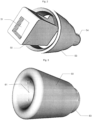
- THE figures 3 And 4 represent views of the cap (12, 22, 32, 42). It has a general cylindrical shape. flared, with a distal section greater than the proximal section.
- the front part (60) has a frustoconical longitudinal channel (61) of circular section opening into a hole (62) corresponding to the microphone vent.
- the rear part (63) has a longitudinal channel of square section (64), complementary to the external section of the base (50) of the microphone support.
- the cover is slipped onto the base (50) after positioning the microphone, to form an assembly protecting the microphone from bad weather and allowing a connection with the rod (10, 20, 30, 40).
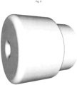
- FIG. 5 represents a variant embodiment of the microphone cap, where the body (60) has a cylindrical shape, pierced by a circular opening (61) of a section less than 50% of the section of the body (60).
- the use of the signals delivered by the four microphones is carried out in a known manner.
- the processing is based on the estimation of the time differences between the sound signals received by pairs of microphones (TDOA, for “Time Difference Of Arrival”, that is to say “difference in time of 'arrival "). These estimates are used, with knowledge of the positions of the microphones, to calculate hyperbolic curves, the intersection of which gives the position of the source.
- the time shifts can in particular be estimated by the so-called PHAT-GCC method (for “PHAse Transform - Generalized Cross-Correlation”, or “phase transformation - generalized intercorrelation”) which uses the calculation of an intercorrelation - or cross-correlation - between signals previously "whitened” by filtering.
- the PHAT-GCC method is described in more detail in the article by Ch. H. Knapp and GC Carter “The Generalized Correlation Method for Estimation of Time Delay”, IEEE Transaction on Acoustics, Speech and Signal Processing, Vol. ASSP-24, No. 4, August 1976 pp. 320 - 327 .
- the processing can also combine the synthesis of a steerable acoustic beam and generalized cross-correlation with phase transformation. This method is called SRP-PHAT (for “Steered Response Power – PHAse Transform” or “directed response power – phase transformation”).
- the information resulting from the analysis of the signals generated by the sound antenna is represented in the form of graphic objects superimposed on the image acquired by the optical sensor (46), for example in the form of an animated sequence or a fixed map accumulation of sound intensities.
- the graphic objects are for example geometric areas superimposed on the image, the color of which is calculated as a function of the instantaneous or cumulative intensity, and the size is representative of the spatial spread of the sound source.
- the signals transmitted by the microphones are digitized to allow the execution of a computer program for calculating time shifts of the PHAT-GCC type.
- This processing provides the angle between a reference axis passing through the geometric center of the four microphones and the source(s), as well as the measured sound intensity of each of these sources.
- FIG. 5 represents a variant embodiment of the microphone cap, where the body (60) has a cylindrical shape, pierced by a circular opening (61) of a section less than 50% of the section of the body (60).
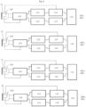
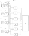
- THE figures 6 And 7 represent the block diagrams of the electronic circuit for processing the signals delivered by the microphones (11, 21, 31, 41).
- processing is carried out making it possible to periodically determine, for example every 100 milliseconds, representative digital data, for each of the microphones, of the sound powers dBA and dBC corresponding to a weighting by the curves A and C which correspond to the sensitivity of the ear. These weightings correct the sound levels measured by the microphones.
- the weightings A and C are in accordance with the usual knowledge of those skilled in the art.
- This calibration table allows you to order a self-calibration of electronic circuits.
- the electronic circuit illustrated by Figure 6 comprises, for each of the microphones (11, 21, 31, 41) generally integrating an analog pre-processing and pre-amplification circuit, an analog-digital converter (111) ensuring the sampling of the signal delivered by the microphone, as well than a correction based on the data read in the EEPROM (110, 210, 310, 410) of the corresponding microphone.
- the digital signals are transmitted to a filter A (112) corresponding to the weighting law A and a filter C (113) corresponding to the weighting law C. These signals are then processed by a module (114, 115) receiving the data offset recorded in the EEPROM (110, 210, 310, 410) of the corresponding microphone.
- This circuit delivers for each of the microphones (11, 21, 31, 41) a pair of digital data dBA, dBC with a periodicity of 100 ms for example.
- the digital signals from each of the analog-digital converters are transmitted to a series of six modules for calculating the time offsets of the pairs of microphones, which are estimated by the so-called PHAT-GCC method (for “PHAse Transform - Generalized Cross- Correlation”, or “phase transformation – generalized intercorrelation”).
- These modules (512, 513, 514, 523, 524, 534) exploit the calculation of an intercorrelation - or cross-correlation - between signals previously “whitened” by filtering.
- a clock (650) ensures the synchronization of the modules (512, 513, 514, 523, 524, 534).
- the PHAT-GCC method is described in more detail in the article by Ch. H. Knapp and GC Carter “The Generalized Correlation Method for Estimation of Time Delay”, IEEE Transaction on Acoustics, Speech and Signal Processing, Vol. ASSP-24, No. 4, August 1976 pp. 320 - 327 .
- the signals representative of the time shifts of the six combinations of pairs of microphones are processed by a processor (600) delivering periodically, for example every 100 milliseconds, a pair of data representative of the angular position along two perpendicular planes of the sound source in relation to at the acoustic center of the antenna.
- the location system further comprises a lidar for measuring the distance from the sound source.
- the laser reflection from the sound source is detected and analyzed by receivers in the lidar sensor. These receivers record the precise period between when the laser pulse leaves the system and when it is returned to calculate the distance between the sensor and the target. These distance measurements are transformed to measurements of actual three-dimensional points of the reflective target in object space.
- the point data is post-processed after studying the collection of lidar data in highly accurate x,y,z coordinates by analyzing the laser time range and laser scanning angle.
- the imaging means (46) consists of two cameras equipped with hypergonal lenses (in English "fish eye") associated with a processing circuit delivering an equidistant cylindrical projection image, also called equirectangular projection.
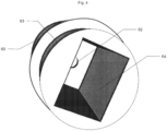
- THE figures 8 and 9 presents an alternative embodiment of a microphone integrated into a cover (12) constituted by a rigid plastic shell having at the rear part an IP67 type connector (70).
- the connector (70) can be engaged in a support (72) formed by a cylindrical base having clipping tabs (73, 74) whose heel engages in an annular groove (75) provided at the rear end of the cap (12). This rear end is also surrounded by an annular seal (76) for example made of Neoprene (trade name) ensuring the tightness of the microphone.
- a support (72) formed by a cylindrical base having clipping tabs (73, 74) whose heel engages in an annular groove (75) provided at the rear end of the cap (12).
- This rear end is also surrounded by an annular seal (76) for example made of Neoprene (trade name) ensuring the tightness of the microphone.
- a cylindrical ring (77) behind the annular groove (75) ensures the precise positioning of the cap (12) relative to the support (72).
Landscapes
- Physics & Mathematics (AREA)
- Engineering & Computer Science (AREA)
- Acoustics & Sound (AREA)
- General Physics & Mathematics (AREA)
- Radar, Positioning & Navigation (AREA)
- Remote Sensing (AREA)
- Signal Processing (AREA)
- Measurement Of Velocity Or Position Using Acoustic Or Ultrasonic Waves (AREA)
Claims (12)
- System zur Lokalisierung mindestens einer Schallquelle, umfassend eine akustische Antenne, die aus vier Mikrophonen (11, 21, 31, 41) besteht, die an den Spitzen eines Tetraeders platziert sind, und eine Schaltung zur Verarbeitung elektrischer Signale, um eine Information, die für die Richtung der Schallquelle in Bezug auf die akustische Antenne repräsentativ ist, zu berechnen, die akustische Antenne ferner umfassend mindestens ein Bildgebungsmittel (46),
dadurch gekennzeichnet, dass das optische Zentrum des Bildgebungsmittels (46) mit dem geometrischen Zentrum des Tetraeders zusammenfällt. - System zur Lokalisierung mindestens einer Schallquelle nach Anspruch 1, dadurch gekennzeichnet, dass die akustische Antenne aus vier nach unten gerichteten Armen (10, 20, 30, 40) besteht, die jeweils an ihrem Ende ein Mikrofon (11, 21, 31, 41) tragen.
- System zur Lokalisierung mindestens einer Schallquelle nach Anspruch 1, dadurch gekennzeichnet, dass die akustische Antenne aus drei nach unten gerichteten Armen (10, 20, 30) gleicher Länge und einem nach oben gerichteten Arm (40) besteht, wobei jeder Arm (10, 20, 30, 40) an seinem Ende ein Mikrofon (11, 21, 31, 41) trägt.
- System zur Lokalisierung mindestens einer Schallquelle nach Anspruch 1, dadurch gekennzeichnet, dass die Mikrofone (11, 21, 31, 41) der MEMS-Art angehören.
- System zur Lokalisierung mindestens einer Schallquelle nach Anspruch 1, dadurch gekennzeichnet, dass jedes Mikrofon eine aktive Komponente, die in eine durch einen Träger und eine Abdeckung (12, 22, 32, 42) aus einem geformten Polymer ausgebildete Einheit integriert ist, umfasst.
- Lokalisierungssystem nach Anspruch 5, dadurch gekennzeichnet, dass jedes der Mikrofone in eine Einheit, die durch einen Träger und eine Abdeckung (12, 22, 32, 42) aus einem geformten Polymer ausgebildet ist, integriert ist.
- Lokalisierungssystem nach Anspruch 6, dadurch gekennzeichnet, dass jedes der Mikrofone in einer Kunststoffeinheit untergebracht ist, die durch einen Träger ausgebildet ist, der an seinem proximalen Ende ein Mittel zur Verbindung mit einem Arm zur Verbindung mit dem Kern der akustischen Antenne aufweist und an seinem distalen Ende einen Sockel (50), der eine Aufnahme (51) für die Positionierung der aktiven Komponente aufweist, eine Abdeckung (12, 22, 32, 42) eine Öffnungsfläche (61), die in ein Loch (62) mündet, das mit der Mikrofonöffnung in Verbindung steht, aufweist und eine Verlängerung (63) einen Kanal (64) mit einem Abschnitt aufweist, der komplementär zu dem Abschnitt des Sockels (50) ist.
- Lokalisierungssystem nach dem vorstehenden Anspruch,
dadurch gekennzeichnet, dass die Abdeckungen eine zylindrische Form (60) mit einer Öffnungsfläche (61), die in ein Loch (62) mündet, das mit der Mikrofonöffnung in Verbindung steht, aufweisen, wobei der Abschnitt des Lochs (61) weniger als 50 % des äußeren Abschnitts der zylindrischen Abdeckung (60) beträgt. - Lokalisierungssystem nach Anspruch 7, dadurch gekennzeichnet, dass die Abdeckungen eine konische Form (60) mit einer konischen Öffnungsfläche (61), die in ein Loch (62) mündet, das mit der Mikrofonöffnung in Verbindung steht, aufweisen, wobei der Eingangsabschnitt des Lochs (61) mehr als 60 % des äußeren Abschnitts der zylindrischen Abdeckung (60) beträgt.
- Lokalisierungssystem nach Anspruch 1, dadurch gekennzeichnet, dass das Lokalisierungssystem ferner ein Lidar für die Messung der Entfernung von der Schallquelle umfasst.
- Lokalisierungssystem nach Anspruch 1, dadurch gekennzeichnet, dass das Bildgebungsmittel (46) aus zwei Kameras, die mit Fischaugenobjektiven (auf Englisch "fish eye") ausgestattet ist, besteht, die mit einer Verarbeitungsschaltung verbunden sind, die ein äquidistantes zylindrisches Projektionsbild liefert.
- Lokalisierungssystem nach Anspruch 6, dadurch gekennzeichnet, dass die Abdeckungen (12, 22, 32, 42) jeweils ein hinteres Ende aufweist, das mit einer ringförmigen Nut (75) versehen ist, die durch einen zylindrischen Ring verlängert ist, der in einen Träger (72) eingreift, der Schnapplaschen (73, 74) aufweist, deren Ansatz in die ringförmige Nut (75) eingreift.
Applications Claiming Priority (2)
| Application Number | Priority Date | Filing Date | Title |
|---|---|---|---|
| FR1759730A FR3072533B1 (fr) | 2017-10-17 | 2017-10-17 | Systeme d'imaginerie de sources acoustiques environnementales |
| PCT/FR2018/052510 WO2019077231A1 (fr) | 2017-10-17 | 2018-10-10 | Systeme d'imagerie de sources acoustiques environnementales |
Publications (3)
| Publication Number | Publication Date |
|---|---|
| EP3698554A1 EP3698554A1 (de) | 2020-08-26 |
| EP3698554B1 true EP3698554B1 (de) | 2023-12-06 |
| EP3698554C0 EP3698554C0 (de) | 2023-12-06 |
Family
ID=61750210
Family Applications (1)
| Application Number | Title | Priority Date | Filing Date |
|---|---|---|---|
| EP18800244.8A Active EP3698554B1 (de) | 2017-10-17 | 2018-10-10 | Bildgebungssystem für umgebungsschallquellen |
Country Status (4)
| Country | Link |
|---|---|
| EP (1) | EP3698554B1 (de) |
| ES (1) | ES2972886T3 (de) |
| FR (1) | FR3072533B1 (de) |
| WO (1) | WO2019077231A1 (de) |
Families Citing this family (4)
| Publication number | Priority date | Publication date | Assignee | Title |
|---|---|---|---|---|
| US11514726B2 (en) | 2020-09-23 | 2022-11-29 | Analog Devices International Unlimited Company | Systems and methods for integrating cameras and phased array antennas for use in electronic toll charge |
| IT202000028430A1 (it) | 2020-11-25 | 2022-05-25 | Leonardo Spa | Metodo di taratura di microfono, in particolare microfono per uso aeronautico |
| FR3131640B1 (fr) | 2021-12-31 | 2024-05-10 | Observatoire Regional Du Bruit En Idf | Systeme de localisation d’une source sonore, notamment de nuisances sonores provenant de vehicules |
| US20230348261A1 (en) | 2022-04-28 | 2023-11-02 | Aivs Inc. | Accelerometer-based acoustic beamformer vector sensor with collocated mems microphone |
Family Cites Families (6)
| Publication number | Priority date | Publication date | Assignee | Title |
|---|---|---|---|---|
| JPH05288598A (ja) * | 1992-04-10 | 1993-11-02 | Ono Sokki Co Ltd | 三次元音響強度計測装置 |
| JP4722347B2 (ja) * | 2000-10-02 | 2011-07-13 | 中部電力株式会社 | 音源探査システム |
| KR101483269B1 (ko) * | 2008-05-06 | 2015-01-21 | 삼성전자주식회사 | 로봇의 음원 위치 탐색 방법 및 그 장치 |
| US9258644B2 (en) * | 2012-07-27 | 2016-02-09 | Nokia Technologies Oy | Method and apparatus for microphone beamforming |
| US10206040B2 (en) * | 2015-10-30 | 2019-02-12 | Essential Products, Inc. | Microphone array for generating virtual sound field |
| KR101678204B1 (ko) * | 2015-12-13 | 2016-12-06 | (주)에스엠인스트루먼트 | 전방향 음장을 전방향 영상에 중첩하여 표현하는 mems 음향센서를 이용한 전방향 음향 시각화 장치 |
-
2017
- 2017-10-17 FR FR1759730A patent/FR3072533B1/fr active Active
-
2018
- 2018-10-10 EP EP18800244.8A patent/EP3698554B1/de active Active
- 2018-10-10 WO PCT/FR2018/052510 patent/WO2019077231A1/fr not_active Ceased
- 2018-10-10 ES ES18800244T patent/ES2972886T3/es active Active
Also Published As
| Publication number | Publication date |
|---|---|
| EP3698554A1 (de) | 2020-08-26 |
| EP3698554C0 (de) | 2023-12-06 |
| FR3072533B1 (fr) | 2019-11-15 |
| WO2019077231A1 (fr) | 2019-04-25 |
| FR3072533A1 (fr) | 2019-04-19 |
| ES2972886T3 (es) | 2024-06-17 |
Similar Documents
| Publication | Publication Date | Title |
|---|---|---|
| US8982363B2 (en) | Method and apparatus to determine depth information for a scene of interest | |
| EP3698554B1 (de) | Bildgebungssystem für umgebungsschallquellen | |
| Kasvi et al. | Comparison of remote sensing based approaches for mapping bathymetry of shallow, clear water rivers | |
| Bodenmann et al. | Generation of high‐resolution three‐dimensional reconstructions of the seafloor in color using a single camera and structured light | |
| EP3653127B1 (de) | Tragbares dreidimensionales ultraschall-bildgebungssystem und -verfahren | |
| FR2847699A1 (fr) | Vehicule autonome, et procede et appareil pour estimer son mouvement et detecter une information tridimensionnelle d'un objet apparaissant devant lui | |
| WO2019158839A1 (fr) | Systeme de signalement de depassement d'un seuil d'intensite sonore | |
| EP3791209B1 (de) | Phasenumhüllungsbestimmung für flugzeitkamera | |
| Markovic et al. | Soundfield imaging in the ray space | |
| Bimber et al. | Synthetic aperture imaging with drones | |
| FR3001301A1 (de) | ||
| FR2950438A1 (fr) | Localisation tridimensionnelle de zone cible terrestre par fusion d'images prises par deux capteurs satellitaires | |
| FR3021411A1 (fr) | Contraintes conjointes de transitivite de differences temporelles et effet dopler multibandes pour la separation, caracterisation, et localisation de sources sonores par acoustique passive | |
| FR2611053A1 (fr) | Dispositif pour detecter de facon continue la distance entre ce dispositif et un point predetermine | |
| KR102144805B1 (ko) | 정사면체형으로 배열된 초소형 음향센서 어레이를 이용한 소형의 전방향 음향 카메라 | |
| EP3070643B1 (de) | Verfahren und system zur objekterkennung durch analyse von signalen eines numerischen bildes einer szene | |
| EP2577225B1 (de) | Vorrichtung und verfahren zur bestimmung der tiefendaten von einem optischen, beweglichen sensor | |
| WO2010001035A2 (fr) | Procédé et dispositif d'estimation d'au moins une composante de vitesse d'une cible mobile. | |
| EP4208731A1 (de) | Verfahren und vorrichtung zur adaptiven verfolgung eines objekts auf lidar-technologiebasis | |
| Qu et al. | An active multimodal sensing platform for remote voice detection | |
| CN119845231B (zh) | 一种基于航空影像和激光点数据融合的海岸带测量方法和系统 | |
| CN214310870U (zh) | 一种基于光学和雷达传感器成像的硬件系统 | |
| FR3029641B1 (fr) | Procede de determination d’une trajectographie par voie passive d’une source mobile par une methode de triangulation inverse | |
| Wu | Self-rotating underwater 3D imaging system based on line-structured light | |
| FR3131640A1 (fr) | Systeme de localisation d’une source sonore, notamment de nuisances sonores provenant de vehicules |
Legal Events
| Date | Code | Title | Description |
|---|---|---|---|
| STAA | Information on the status of an ep patent application or granted ep patent |
Free format text: STATUS: UNKNOWN |
|
| STAA | Information on the status of an ep patent application or granted ep patent |
Free format text: STATUS: THE INTERNATIONAL PUBLICATION HAS BEEN MADE |
|
| PUAI | Public reference made under article 153(3) epc to a published international application that has entered the european phase |
Free format text: ORIGINAL CODE: 0009012 |
|
| STAA | Information on the status of an ep patent application or granted ep patent |
Free format text: STATUS: REQUEST FOR EXAMINATION WAS MADE |
|
| 17P | Request for examination filed |
Effective date: 20200409 |
|
| AK | Designated contracting states |
Kind code of ref document: A1 Designated state(s): AL AT BE BG CH CY CZ DE DK EE ES FI FR GB GR HR HU IE IS IT LI LT LU LV MC MK MT NL NO PL PT RO RS SE SI SK SM TR |
|
| AX | Request for extension of the european patent |
Extension state: BA ME |
|
| DAV | Request for validation of the european patent (deleted) | ||
| DAX | Request for extension of the european patent (deleted) | ||
| STAA | Information on the status of an ep patent application or granted ep patent |
Free format text: STATUS: EXAMINATION IS IN PROGRESS |
|
| 17Q | First examination report despatched |
Effective date: 20211025 |
|
| REG | Reference to a national code |
Ref country code: DE Ref legal event code: R079 Free format text: PREVIOUS MAIN CLASS: H04R0001080000 Ipc: G01S0003801000 Ref document number: 602018062286 Country of ref document: DE |
|
| GRAP | Despatch of communication of intention to grant a patent |
Free format text: ORIGINAL CODE: EPIDOSNIGR1 |
|
| STAA | Information on the status of an ep patent application or granted ep patent |
Free format text: STATUS: GRANT OF PATENT IS INTENDED |
|
| RIC1 | Information provided on ipc code assigned before grant |
Ipc: H04R 1/40 20060101ALN20230316BHEP Ipc: H04R 3/00 20060101ALN20230316BHEP Ipc: H04R 5/027 20060101ALI20230316BHEP Ipc: G01H 3/12 20060101ALI20230316BHEP Ipc: H04R 1/08 20060101ALI20230316BHEP Ipc: G01S 3/808 20060101ALI20230316BHEP Ipc: G01S 3/801 20060101AFI20230316BHEP |
|
| RIC1 | Information provided on ipc code assigned before grant |
Ipc: H04R 1/40 20060101ALN20230328BHEP Ipc: H04R 3/00 20060101ALN20230328BHEP Ipc: H04R 5/027 20060101ALI20230328BHEP Ipc: G01H 3/12 20060101ALI20230328BHEP Ipc: H04R 1/08 20060101ALI20230328BHEP Ipc: G01S 3/808 20060101ALI20230328BHEP Ipc: G01S 3/801 20060101AFI20230328BHEP |
|
| INTG | Intention to grant announced |
Effective date: 20230418 |
|
| GRAS | Grant fee paid |
Free format text: ORIGINAL CODE: EPIDOSNIGR3 |
|
| GRAA | (expected) grant |
Free format text: ORIGINAL CODE: 0009210 |
|
| STAA | Information on the status of an ep patent application or granted ep patent |
Free format text: STATUS: THE PATENT HAS BEEN GRANTED |
|
| AK | Designated contracting states |
Kind code of ref document: B1 Designated state(s): AL AT BE BG CH CY CZ DE DK EE ES FI FR GB GR HR HU IE IS IT LI LT LU LV MC MK MT NL NO PL PT RO RS SE SI SK SM TR |
|
| REG | Reference to a national code |
Ref country code: GB Ref legal event code: FG4D Free format text: NOT ENGLISH |
|
| REG | Reference to a national code |
Ref country code: CH Ref legal event code: EP |
|
| REG | Reference to a national code |
Ref country code: DE Ref legal event code: R096 Ref document number: 602018062286 Country of ref document: DE |
|
| REG | Reference to a national code |
Ref country code: IE Ref legal event code: FG4D Free format text: LANGUAGE OF EP DOCUMENT: FRENCH |
|
| U01 | Request for unitary effect filed |
Effective date: 20240103 |
|
| U07 | Unitary effect registered |
Designated state(s): AT BE BG DE DK EE FI FR IT LT LU LV MT NL PT SE SI Effective date: 20240112 |
|
| PG25 | Lapsed in a contracting state [announced via postgrant information from national office to epo] |
Ref country code: GR Free format text: LAPSE BECAUSE OF FAILURE TO SUBMIT A TRANSLATION OF THE DESCRIPTION OR TO PAY THE FEE WITHIN THE PRESCRIBED TIME-LIMIT Effective date: 20240307 |
|
| PG25 | Lapsed in a contracting state [announced via postgrant information from national office to epo] |
Ref country code: GR Free format text: LAPSE BECAUSE OF FAILURE TO SUBMIT A TRANSLATION OF THE DESCRIPTION OR TO PAY THE FEE WITHIN THE PRESCRIBED TIME-LIMIT Effective date: 20240307 |
|
| PG25 | Lapsed in a contracting state [announced via postgrant information from national office to epo] |
Ref country code: RS Free format text: LAPSE BECAUSE OF FAILURE TO SUBMIT A TRANSLATION OF THE DESCRIPTION OR TO PAY THE FEE WITHIN THE PRESCRIBED TIME-LIMIT Effective date: 20231206 Ref country code: NO Free format text: LAPSE BECAUSE OF FAILURE TO SUBMIT A TRANSLATION OF THE DESCRIPTION OR TO PAY THE FEE WITHIN THE PRESCRIBED TIME-LIMIT Effective date: 20240306 Ref country code: HR Free format text: LAPSE BECAUSE OF FAILURE TO SUBMIT A TRANSLATION OF THE DESCRIPTION OR TO PAY THE FEE WITHIN THE PRESCRIBED TIME-LIMIT Effective date: 20231206 |
|
| REG | Reference to a national code |
Ref country code: ES Ref legal event code: FG2A Ref document number: 2972886 Country of ref document: ES Kind code of ref document: T3 Effective date: 20240617 |
|
| PG25 | Lapsed in a contracting state [announced via postgrant information from national office to epo] |
Ref country code: IS Free format text: LAPSE BECAUSE OF FAILURE TO SUBMIT A TRANSLATION OF THE DESCRIPTION OR TO PAY THE FEE WITHIN THE PRESCRIBED TIME-LIMIT Effective date: 20240406 |
|
| PG25 | Lapsed in a contracting state [announced via postgrant information from national office to epo] |
Ref country code: CZ Free format text: LAPSE BECAUSE OF FAILURE TO SUBMIT A TRANSLATION OF THE DESCRIPTION OR TO PAY THE FEE WITHIN THE PRESCRIBED TIME-LIMIT Effective date: 20231206 |
|
| PG25 | Lapsed in a contracting state [announced via postgrant information from national office to epo] |
Ref country code: SK Free format text: LAPSE BECAUSE OF FAILURE TO SUBMIT A TRANSLATION OF THE DESCRIPTION OR TO PAY THE FEE WITHIN THE PRESCRIBED TIME-LIMIT Effective date: 20231206 |
|
| PG25 | Lapsed in a contracting state [announced via postgrant information from national office to epo] |
Ref country code: SM Free format text: LAPSE BECAUSE OF FAILURE TO SUBMIT A TRANSLATION OF THE DESCRIPTION OR TO PAY THE FEE WITHIN THE PRESCRIBED TIME-LIMIT Effective date: 20231206 Ref country code: SK Free format text: LAPSE BECAUSE OF FAILURE TO SUBMIT A TRANSLATION OF THE DESCRIPTION OR TO PAY THE FEE WITHIN THE PRESCRIBED TIME-LIMIT Effective date: 20231206 Ref country code: RO Free format text: LAPSE BECAUSE OF FAILURE TO SUBMIT A TRANSLATION OF THE DESCRIPTION OR TO PAY THE FEE WITHIN THE PRESCRIBED TIME-LIMIT Effective date: 20231206 Ref country code: IS Free format text: LAPSE BECAUSE OF FAILURE TO SUBMIT A TRANSLATION OF THE DESCRIPTION OR TO PAY THE FEE WITHIN THE PRESCRIBED TIME-LIMIT Effective date: 20240406 Ref country code: CZ Free format text: LAPSE BECAUSE OF FAILURE TO SUBMIT A TRANSLATION OF THE DESCRIPTION OR TO PAY THE FEE WITHIN THE PRESCRIBED TIME-LIMIT Effective date: 20231206 |
|
| PG25 | Lapsed in a contracting state [announced via postgrant information from national office to epo] |
Ref country code: PL Free format text: LAPSE BECAUSE OF FAILURE TO SUBMIT A TRANSLATION OF THE DESCRIPTION OR TO PAY THE FEE WITHIN THE PRESCRIBED TIME-LIMIT Effective date: 20231206 |
|
| PG25 | Lapsed in a contracting state [announced via postgrant information from national office to epo] |
Ref country code: PL Free format text: LAPSE BECAUSE OF FAILURE TO SUBMIT A TRANSLATION OF THE DESCRIPTION OR TO PAY THE FEE WITHIN THE PRESCRIBED TIME-LIMIT Effective date: 20231206 |
|
| REG | Reference to a national code |
Ref country code: DE Ref legal event code: R097 Ref document number: 602018062286 Country of ref document: DE |
|
| PLBE | No opposition filed within time limit |
Free format text: ORIGINAL CODE: 0009261 |
|
| STAA | Information on the status of an ep patent application or granted ep patent |
Free format text: STATUS: NO OPPOSITION FILED WITHIN TIME LIMIT |
|
| 26N | No opposition filed |
Effective date: 20240909 |
|
| U20 | Renewal fee for the european patent with unitary effect paid |
Year of fee payment: 7 Effective date: 20241031 |
|
| PG25 | Lapsed in a contracting state [announced via postgrant information from national office to epo] |
Ref country code: MC Free format text: LAPSE BECAUSE OF FAILURE TO SUBMIT A TRANSLATION OF THE DESCRIPTION OR TO PAY THE FEE WITHIN THE PRESCRIBED TIME-LIMIT Effective date: 20231206 |
|
| PG25 | Lapsed in a contracting state [announced via postgrant information from national office to epo] |
Ref country code: IE Free format text: LAPSE BECAUSE OF NON-PAYMENT OF DUE FEES Effective date: 20241010 |
|
| REG | Reference to a national code |
Ref country code: CH Ref legal event code: U11 Free format text: ST27 STATUS EVENT CODE: U-0-0-U10-U11 (AS PROVIDED BY THE NATIONAL OFFICE) Effective date: 20251101 |
|
| U20 | Renewal fee for the european patent with unitary effect paid |
Year of fee payment: 8 Effective date: 20251028 |
|
| PGFP | Annual fee paid to national office [announced via postgrant information from national office to epo] |
Ref country code: GB Payment date: 20251022 Year of fee payment: 8 |
|
| PGFP | Annual fee paid to national office [announced via postgrant information from national office to epo] |
Ref country code: CH Payment date: 20251101 Year of fee payment: 8 |
|
| PG25 | Lapsed in a contracting state [announced via postgrant information from national office to epo] |
Ref country code: CY Free format text: LAPSE BECAUSE OF FAILURE TO SUBMIT A TRANSLATION OF THE DESCRIPTION OR TO PAY THE FEE WITHIN THE PRESCRIBED TIME-LIMIT; INVALID AB INITIO Effective date: 20181010 |
|
| PGFP | Annual fee paid to national office [announced via postgrant information from national office to epo] |
Ref country code: ES Payment date: 20251216 Year of fee payment: 8 |
|
| PG25 | Lapsed in a contracting state [announced via postgrant information from national office to epo] |
Ref country code: HU Free format text: LAPSE BECAUSE OF FAILURE TO SUBMIT A TRANSLATION OF THE DESCRIPTION OR TO PAY THE FEE WITHIN THE PRESCRIBED TIME-LIMIT; INVALID AB INITIO Effective date: 20181010 |