EP3698058B1 - Multiple piece high security fastener - Google Patents
Multiple piece high security fastener Download PDFInfo
- Publication number
- EP3698058B1 EP3698058B1 EP18797332.6A EP18797332A EP3698058B1 EP 3698058 B1 EP3698058 B1 EP 3698058B1 EP 18797332 A EP18797332 A EP 18797332A EP 3698058 B1 EP3698058 B1 EP 3698058B1
- Authority
- EP
- European Patent Office
- Prior art keywords
- shroud
- fastener
- central axis
- annular
- intermediate sleeve
- Prior art date
- Legal status (The legal status is an assumption and is not a legal conclusion. Google has not performed a legal analysis and makes no representation as to the accuracy of the status listed.)
- Active
Links
- 230000000452 restraining effect Effects 0.000 claims description 15
- 239000004033 plastic Substances 0.000 claims description 14
- 229920003023 plastic Polymers 0.000 claims description 14
- 239000000463 material Substances 0.000 claims description 11
- 229920000642 polymer Polymers 0.000 claims description 9
- 229910000906 Bronze Inorganic materials 0.000 claims description 8
- 239000010974 bronze Substances 0.000 claims description 8
- KUNSUQLRTQLHQQ-UHFFFAOYSA-N copper tin Chemical compound [Cu].[Sn] KUNSUQLRTQLHQQ-UHFFFAOYSA-N 0.000 claims description 8
- 239000000314 lubricant Substances 0.000 claims description 7
- 229920001343 polytetrafluoroethylene Polymers 0.000 claims description 7
- 239000004810 polytetrafluoroethylene Substances 0.000 claims description 7
- 229910000640 Fe alloy Inorganic materials 0.000 claims description 6
- 239000004677 Nylon Substances 0.000 claims description 6
- 238000009434 installation Methods 0.000 claims description 6
- 229920001778 nylon Polymers 0.000 claims description 6
- -1 polytetrafluoroethylene Polymers 0.000 claims description 3
- OKTJSMMVPCPJKN-UHFFFAOYSA-N Carbon Chemical compound [C] OKTJSMMVPCPJKN-UHFFFAOYSA-N 0.000 claims description 2
- 229910002804 graphite Inorganic materials 0.000 claims description 2
- 239000010439 graphite Substances 0.000 claims description 2
- 230000004323 axial length Effects 0.000 description 5
- 229910000831 Steel Inorganic materials 0.000 description 4
- 239000010959 steel Substances 0.000 description 4
- 229910045601 alloy Inorganic materials 0.000 description 3
- 239000000956 alloy Substances 0.000 description 3
- 239000010935 stainless steel Substances 0.000 description 3
- 229910001220 stainless steel Inorganic materials 0.000 description 3
- XEEYBQQBJWHFJM-UHFFFAOYSA-N Iron Chemical compound [Fe] XEEYBQQBJWHFJM-UHFFFAOYSA-N 0.000 description 2
- PXHVJJICTQNCMI-UHFFFAOYSA-N Nickel Chemical compound [Ni] PXHVJJICTQNCMI-UHFFFAOYSA-N 0.000 description 2
- 239000000919 ceramic Substances 0.000 description 2
- 238000000576 coating method Methods 0.000 description 2
- 238000012986 modification Methods 0.000 description 2
- 230000004048 modification Effects 0.000 description 2
- 239000005060 rubber Substances 0.000 description 2
- 229910001369 Brass Inorganic materials 0.000 description 1
- VYZAMTAEIAYCRO-UHFFFAOYSA-N Chromium Chemical compound [Cr] VYZAMTAEIAYCRO-UHFFFAOYSA-N 0.000 description 1
- RTAQQCXQSZGOHL-UHFFFAOYSA-N Titanium Chemical compound [Ti] RTAQQCXQSZGOHL-UHFFFAOYSA-N 0.000 description 1
- 238000005299 abrasion Methods 0.000 description 1
- 229910052782 aluminium Inorganic materials 0.000 description 1
- XAGFODPZIPBFFR-UHFFFAOYSA-N aluminium Chemical compound [Al] XAGFODPZIPBFFR-UHFFFAOYSA-N 0.000 description 1
- 230000000712 assembly Effects 0.000 description 1
- 238000000429 assembly Methods 0.000 description 1
- 230000004888 barrier function Effects 0.000 description 1
- 238000005452 bending Methods 0.000 description 1
- 239000010951 brass Substances 0.000 description 1
- 239000011248 coating agent Substances 0.000 description 1
- 238000010276 construction Methods 0.000 description 1
- 238000002788 crimping Methods 0.000 description 1
- 229910052742 iron Inorganic materials 0.000 description 1
- 239000002184 metal Substances 0.000 description 1
- 229910052751 metal Inorganic materials 0.000 description 1
- 229910052759 nickel Inorganic materials 0.000 description 1
- 238000007747 plating Methods 0.000 description 1
- 239000002861 polymer material Substances 0.000 description 1
- 238000009877 rendering Methods 0.000 description 1
- 230000000717 retained effect Effects 0.000 description 1
- 229910052709 silver Inorganic materials 0.000 description 1
- 239000004332 silver Substances 0.000 description 1
- 238000009987 spinning Methods 0.000 description 1
- 230000003068 static effect Effects 0.000 description 1
- 239000010936 titanium Substances 0.000 description 1
- 229910052719 titanium Inorganic materials 0.000 description 1
Images


Classifications
-
- B—PERFORMING OPERATIONS; TRANSPORTING
- B60—VEHICLES IN GENERAL
- B60B—VEHICLE WHEELS; CASTORS; AXLES FOR WHEELS OR CASTORS; INCREASING WHEEL ADHESION
- B60B3/00—Disc wheels, i.e. wheels with load-supporting disc body
- B60B3/14—Attaching disc body to hub ; Wheel adapters
- B60B3/16—Attaching disc body to hub ; Wheel adapters by bolts or the like
- B60B3/165—Attaching disc body to hub ; Wheel adapters by bolts or the like with locking devices for the fixing means, e.g. screw or nut covers
-
- F—MECHANICAL ENGINEERING; LIGHTING; HEATING; WEAPONS; BLASTING
- F16—ENGINEERING ELEMENTS AND UNITS; GENERAL MEASURES FOR PRODUCING AND MAINTAINING EFFECTIVE FUNCTIONING OF MACHINES OR INSTALLATIONS; THERMAL INSULATION IN GENERAL
- F16B—DEVICES FOR FASTENING OR SECURING CONSTRUCTIONAL ELEMENTS OR MACHINE PARTS TOGETHER, e.g. NAILS, BOLTS, CIRCLIPS, CLAMPS, CLIPS OR WEDGES; JOINTS OR JOINTING
- F16B37/00—Nuts or like thread-engaging members
- F16B37/14—Cap nuts; Nut caps or bolt caps
-
- F—MECHANICAL ENGINEERING; LIGHTING; HEATING; WEAPONS; BLASTING
- F16—ENGINEERING ELEMENTS AND UNITS; GENERAL MEASURES FOR PRODUCING AND MAINTAINING EFFECTIVE FUNCTIONING OF MACHINES OR INSTALLATIONS; THERMAL INSULATION IN GENERAL
- F16B—DEVICES FOR FASTENING OR SECURING CONSTRUCTIONAL ELEMENTS OR MACHINE PARTS TOGETHER, e.g. NAILS, BOLTS, CIRCLIPS, CLAMPS, CLIPS OR WEDGES; JOINTS OR JOINTING
- F16B39/00—Locking of screws, bolts or nuts
- F16B39/02—Locking of screws, bolts or nuts in which the locking takes place after screwing down
- F16B39/025—Locking of screws, bolts or nuts in which the locking takes place after screwing down by plastic deformation of a part of one of the threaded elements into a notch or cavity of the other threaded element
-
- F—MECHANICAL ENGINEERING; LIGHTING; HEATING; WEAPONS; BLASTING
- F16—ENGINEERING ELEMENTS AND UNITS; GENERAL MEASURES FOR PRODUCING AND MAINTAINING EFFECTIVE FUNCTIONING OF MACHINES OR INSTALLATIONS; THERMAL INSULATION IN GENERAL
- F16B—DEVICES FOR FASTENING OR SECURING CONSTRUCTIONAL ELEMENTS OR MACHINE PARTS TOGETHER, e.g. NAILS, BOLTS, CIRCLIPS, CLAMPS, CLIPS OR WEDGES; JOINTS OR JOINTING
- F16B39/00—Locking of screws, bolts or nuts
- F16B39/02—Locking of screws, bolts or nuts in which the locking takes place after screwing down
- F16B39/12—Locking of screws, bolts or nuts in which the locking takes place after screwing down by means of locknuts
-
- F—MECHANICAL ENGINEERING; LIGHTING; HEATING; WEAPONS; BLASTING
- F16—ENGINEERING ELEMENTS AND UNITS; GENERAL MEASURES FOR PRODUCING AND MAINTAINING EFFECTIVE FUNCTIONING OF MACHINES OR INSTALLATIONS; THERMAL INSULATION IN GENERAL
- F16B—DEVICES FOR FASTENING OR SECURING CONSTRUCTIONAL ELEMENTS OR MACHINE PARTS TOGETHER, e.g. NAILS, BOLTS, CIRCLIPS, CLAMPS, CLIPS OR WEDGES; JOINTS OR JOINTING
- F16B41/00—Measures against loss of bolts, nuts, or pins; Measures against unauthorised operation of bolts, nuts or pins
- F16B41/005—Measures against unauthorised operation of bolts, nuts or pins
-
- B—PERFORMING OPERATIONS; TRANSPORTING
- B60—VEHICLES IN GENERAL
- B60B—VEHICLE WHEELS; CASTORS; AXLES FOR WHEELS OR CASTORS; INCREASING WHEEL ADHESION
- B60B2900/00—Purpose of invention
- B60B2900/30—Increase in
- B60B2900/331—Safety or security
- B60B2900/3318—Safety or security by theft prevention
Definitions
- the present invention relates to high security fasteners, and more particularly to a high security fastener having multiple piece or limited contact cap or shroud.
- Locking wheel nuts and wheel bolts are commonly used to attach wheels to axel hub assemblies of automobiles and other vehicles. These fasteners are designed with security features that are intended to thwart theft by rendering the fasteners difficult to remove with conventional tools. In particular, the fasteners do not have the usual hexagonal head pattern found on conventional nuts and bolts and instead have smooth cylindrical sidewalls that cannot be gripped by standard wrenches. Fastener removal requires the use of a special security tool having a unique key pattern that matches a corresponding groove pattern formed in the fastener end face.
- Additional security can be obtained by fitting a free-spinning shroud or cap over the security fasteners cylindrical sidewalls, such that the shroud is in concentric relationship therewith.
- the shroud discourages the use of theft devices that could otherwise be used to grip the sidewalls and remove the fastener without an authorized security tool. Because the shroud substantially surrounds all exposed surfaces of the sidewalls, no rotational purchase can be obtained in the fastener.
- the theft device can only engage the shroud, which freely spins under action of the theft device while the main body of the fastener remains stationary.
- an improved fastener (15, 15a, 15b, 15c, 15d, 15e) comprising : a fastener body (16, 16e) orientated about a central axis (x-x); the fastener body having a tool-engaging portion (17) to which a driving torque may be applied and a threaded fastening portion (18) configured and arranged to mate with a corresponding threaded element; the fastener body having a shroud-receiving body portion (19, 19e) orientated about the central axis; a shroud (20, 20d) concentrically mounted on the shroud-receiving body portion; an intermediate sleeve (50, 50a, 50b, 50c, 50d, 50e) disposed concentrically between the shroud-receiving body portion and the shroud; the shroud having an inner
- the outer surface of the intermediate sleeve may have a coefficient of friction less than the outer surface of the shroud-receiving body portion.
- the inner surface of the intermediate sleeve may have a coefficient of friction less than the outer surface of the shroud-receiving body portion.
- the outer surface of the intermediate sleeve may have coefficient of friction less than the inner surface of the shroud.
- the intermediate sleeve may comprise a lubricant-releasing medium or a polymer.
- the intermediate sleeve may comprise a material selected from a group consisting of a lubricant-impregnated nylon plastic, a lubricant-filled nylon plastic, a polytetrafluoroethylene (PTFE) releasing polymer, a graphite impregnated porous bronze or iron alloy, and a lubricant-impregnated porous bronze or iron alloy.
- a lubricant-impregnated nylon plastic a lubricant-filled nylon plastic
- PTFE polytetrafluoroethylene
- the intermediate sleeve may be supported in rotatable relationship with the shroud-receiving body portion and the shroud such that the intermediate sleeve is rotatable about the central axis relative to both the fastener body and the shroud.
- the fastener body may comprise a lock nut or a lock bolt.
- the fastener may comprise a first sleeve-retaining element (38) restraining the intermediate sleeve from movement in at least a first axial direction along the central axis relative to the fastener body and a second sleeve-retaining element (39) restraining the intermediate sleeve from movement in at least a second axial direction along the central axis opposite to the first axial direction along the central axis relative to the fastener body.
- the first shroud-retaining element may comprise a surface (28, 28e) of the fastener body and the second shroud-retaining element may comprise a surface (24, 24e) of the fastener body.
- the first sleeve-retaining element may comprise a surface (26, 26e) of the fastener body and the second sleeve-retaining element may comprise a surface (47, 47d) of the shroud.
- the first sleeve-retaining element may comprise an annular shoulder (38) of the fastener body facing an opposed annular end (53, 53a, 53b, 53c, 53d, 53e) of the intermediate sleeve.
- the second sleeve-retaining element may comprise an annular flange (39) of the shroud facing an opposed annular end of the intermediate sleeve (51, 51a, 51b, 51c, 51d, 51e).
- the first shroud-retaining element may comprise an annular end portion (49, 49d) of the shroud bent inwardly transverse to the central axis and facing an opposed annular step (28, 28d) of the fastener body.
- the second shroud-retaining element may comprise the annular flange (39) of the shroud facing an opposed annular end (24, 24e) of the fastener body.
- a coefficient of friction between the outer surface of the intermediate sleeve and the inner surface of the shroud may be less than a coefficient of friction between the outer surface of the shroud-receiving body portion and the inner surface of the shroud.
- the coefficient of friction between the outer surface of the intermediate sleeve and the inner surface of the shroud may be less than about 0.2.
- the coefficient of friction between the outer surface of the intermediate sleeve and the inner surface of the shroud may be less than about 0.05.
- the inner surface (46, 46d) of the shroud may be not substantially parallel to the outer surface (54, 54c, 54d) of the intermediate sleeve and the inner surface of the intermediate sleeve (52, 52a, 52b, 52d) may be substantially parallel to the outer surface (25) of the shroud-receiving body portion.
- the inner surface (46) of the shroud may be a substantially cylindrical surface along the axially overlapping portion and the outer surface (54, 54c) of the intermediate sleeve may be a substantially convex curved surface along the axially overlapping portion.
- the outer surface of the shroud-receiving body portion (25) may be a substantially cylindrical surface along the axially overlapping portion and the inner surface (52b, 52c) of the intermediate sleeve may be a substantially convex curved surface along the axially overlapping portion.
- the outer surface (54a, 54b, 54d, 54e) of the intermediate sleeve may be a substantially cylindrical surface along the axially overlapping portion and the inner surface (46d) of the shroud may be a substantially convex curved surface along the axially overlapping portion.
- the inner surface (52, 52a, 52d, 52e) of the intermediate sleeve may be a substantially cylindrical surface along the axially overlapping portion and the outer surface (25e) of the shroud-receiving body portion may be a substantially convex curved surface along the axially overlapping portion.
- a fastener comprising: a fastener body (116, 116a) orientated about a central axis (x-x); the fastener body having a tool-engaging portion (117) to which a driving torque may be applied and a threaded fastening portion (118) configured and arranged to mate with a corresponding threaded element; the fastener body having a shroud-receiving body portion (119, 119a) orientated about the central axis; a shroud (20) concentrically mounted on the shroud-receiving body portion; a first shroud-retaining element (149) at a first axial position along the central axis restraining the shroud from movement in at least a first axial direction along the central axis relative to the fastener body; a second shroud-retaining element (39) at a second axial position along the central axis restraining the shroud from movement
- the shroud inner surface is not substantially parallel to the body outer surface along the axially overlapping portion.
- the shroud inner surface (46) comprises a substantially cylindrical surface along the axially overlapping portion and the body outer surface (125, 125a-f) comprises a convex curved surface along the axially overlapping portion.
- the shroud may be supported in rotatable relationship with the shroud-receiving body portion at no more than three discrete annular contact regions (70, 70a, 71, 71a, 72, 72a).
- the annular contact regions may comprise a first annular contact region (70, 70a) defined by the first shroud retaining element, a second annular contact region (72, 72a) defined by the second shroud retaining element, and an intermediate annular contact region (71, 71a) positioned axially between the first annular contact region and the second annular contact region.
- the first shroud-retaining element may comprise an annular end portion (49) of the shroud bent inwardly transverse to the central axis and facing an opposed annular step (128, 128a) of the fastener body.
- the second shroud-retaining element may comprise an annular flange (39) of the shroud facing an opposed annular end (124, 124a) of the fastener body.
- the intermediate annular region (71, 71a) may be between the first annular contact region and the second annular contact region at an axial position at which the annular varying radial gap is a minimum (161).
- the shroud inner surface (46) may comprise a substantially cylindrical surface along the axially overlapping portion and the body outer surface (225) may comprise a convex curved surface (125a-f) along the axially overlapping portion having multiple grooves (90a-90f) extending longitudinally therein.
- the annular varying radial gap may have a cross-sectional area in a plane generally perpendicular to the central axis and the cross-section area may be not uniform along the axially overlapping portion.
- the cross-section area may vary from a minimum cross-sectional area at a first axial position (161) along the axially overlapping portion to a maximum cross-sectional area (162) at a second axial position along the axially overlapping portion.
- the terms “horizontal”, “vertical”, “left”, “right”, “up” and “down”, as well as adjectival and adverbial derivatives thereof simply refer to the orientation of the illustrated structure as the particular drawing figure faces the reader.
- the terms “inwardly” and “outwardly” generally refer to the orientation of a surface relative to its axis of elongation, or axis of rotation, as appropriate.
- Fastener 15 generally includes fastener body 16, cap or shroud 20, which rotates about axis x-x relative to fastener body 16, and intermediate sleeve 50, which is rotatable about axis x-x relative to both fastener body 16 and shroud 20.
- Fastener body 16 includes threaded fastening portion 18, inner tool engaging portion 17, and outer shroud-retaining portion 19, on which sleeve 50 and shroud 20 are each rotationally and concentrically supported.
- fastener body 16 is a specially configured cylindrical member elongated along axis x-x and is generally bounded by rightwardly-facing vertical annular surface 24, outwardly-facing horizontal cylindrical surface 25, rightwardly-facing annular vertical surface 26, outwardly-facing horizontal cylindrical surface 27, leftwardly and outwardly-facing frusto-conical surface 28, outwardly-facing horizontal cylindrical surface 29, leftwardly and outwardly-facing frusto-conical surface 30, leftwardly-facing vertical annular surface 31, inwardly-facing horizontal cylindrical surface 32, leftwardly and inwardly-facing frusto-conical surface 33, inwardly-facing horizontal cylindrical surface 34, rightwardly-facing vertical annular surface 35, and inwardly-facing horizontal key patterned cylindrical surface 36.
- Threaded fastening portion 18 of fastener body 16 includes cylindrical bore 21, defined by surface 34, that extends inwardly from the left face 31 of body 16 and is internally threaded over a portion or all of its length.
- Nut fastener 15 may be installed in a wheel having a recess hole formed as a relatively deep cylindrical well. The wheel hole has an annular recess entrance and a wheel stud or post in the wheel hole, and fastener body 16 and fastening portion 18 are sized and installed such that the interior threads of inner bore 21 engage the corresponding exterior threads of the wheel stud in the wheel hole.
- Tool engaging portion 17 of fastener body 16 includes specially configured inner cavity or socket 22, defined by lock patterned surface 36, that extends inwardly from right end face 24 of body 16 and has a specially configured internal profile to which a drive torque may be applied.
- This internal profile comprises a key-receiving pattern that may be implemented as a set of circumferentially spaced internally facing longitudinally extending key-receiving grooves 23 arranged in a lock pattern to which a drive torque may be applied, with the entrance to socket 22 formed with the key lock pattern.
- lock pattern grooves 23 are visible on the annular right front face 24 of tool engaging portion 17.
- lock pattern grooves 23 may be patterned or configured in any suitable alternative manner, such as by employing a selected number of grooves and/or by varying other features thereof, such as the spacing between grooves and/or the width, length, depth, profile or other configuration or feature thereof. Such grooves are configured so that a corresponding drive key tool (no shown) may be used to engage lock pattern grooves 23.
- the key includes a drive shaft formed with a key pattern that may be implemented as a set of circumferentially arranged key pattern lobes that are configured and arranged to engage lock pattern grooves 23 in socket 22 when the drive shaft is properly aligned and placed in bore 22 of nut fastener 15.
- a key having a matching set of key pattern lobes may be used to engage lock pattern grooves 23 to actuate nut fastener 15 about axis x-x.
- the security key is configured to fit within bore 22 to engage the lock pattern and rotate nut fastener 15. Other tools either will not fit within bore 22 or will not be able to properly engage and rotate nut fastener 15 when it is installed at its intended design installation torque.
- shroud 20 to spin relative to sleeve 50 and fastener body 16 thereof provides a security feature that protects fastener 15 from being used as a purchase point for unauthorized tools. Should an attempt be made to rotate fastener 15 by gripping the exposed end, cap 20 will tend to spin without any rotation being imparted to fastener body 16 and fastening portion 18 thereof.
- Surfaces 24, 25, 26, 27 and 28 generally define shroud-retaining portion 19.
- retaining portion 19 of fastener body 16 comprises cylindrical surface 25 orientated about axis x-x and axially bounded at one end by shoulder 38, defined by annular surface 26, and axially bounded at the other end by a step defined by annular end surface 24.
- Cylindrical surface 25 has outer diameter 61.
- Sleeve 50 extends over and around shroud receiving portion 19 and is separately formed from shroud 20 and fastener body 16.
- sleeve 50 is a specially configured cylindrical member elongated along axis x-x and is generally bounded by rightwardly-facing vertical annular surface 51, inwardly-facing horizontal cylindrical surface 52, leftwardly-facing vertical annular surface 53, and outwardly-facing convex surface 54.
- sleeve 50 includes inner bore 55, defined by surface 52, having uniform inside diameter 62 that is approximately the same size as outside diameter 61 of retaining portion 19.
- outer surface 54 has a convex longitudinal profile or barrel shape relative to axis x-x, curving from minimum outside diameter 65 at left annular face 53 and right annular face 51, respectively, to maximum outside diameter 63 at the axial midpoint between left annular face 53 and right annular face 51.
- sleeve 50 may have other outside surface profiles.
- Shroud 20 extends over and around sleeve 50 and retaining portion 19 of fastener body 16.
- shroud 20 is a specially configured cylindrical member elongated along axis x-x and is generally bounded by rightwardly-facing vertical annular surface 40, outwardly-facing horizontal cylindrical surface 41, leftwardly and outwardly-facing frusto-conical surface 42, outwardly-facing horizontal cylindrical surface 43, leftwardly and outwardly-facing frusto-conical surface 44, leftwardly-facing vertical annular surface 45, inwardly-facing horizontal cylindrical surface 46, leftwardly-facing vertical annular surface 47, and inwardly-facing horizontal cylindrical surface 48.
- shroud 20 includes inner bore 56, defined by surface 47, having uniform inside diameter 64 just slightly larger than the maximum outside diameter 63 of convex surface 54 of sleeve 50.
- sleeve 50 has been placed over left distal end 24 of body 16 such that leftwardly-facing annular end face 53 of sleeve 50 abuts against rightwardly-facing annular shoulder surface 26 of retaining portion 19.
- sleeve 50 has an axial width such that rightwardly-facing annular end face 51 of sleeve 50 is axially to the left of or aligned with rightwardly-facing annular end face 24 of retaining portion 19 of fastener body 16.
- shroud 20 has in turn been placed over left distal end 24 of body 16 such that the inner annular portion of leftwardly-facing annular surface 47 of flange 39 of shroud 20 abuts against rightwardly-facing annular end face 24 of retaining portion 19 of fastener body 16.
- the left thin-walled tubular end 49 of shroud 20 is dimensioned to extend leftwardly a distance beyond shoulder 38 of fastener body 16, defined by surfaces 26, 27 and 28.
- this extension When assembled as described below, this extension will be reduced in axial length along axis x-x as end portion 49 of shroud 20 deforms and bends or curls inwardly against the sloped left surface 28 of shoulder 38 of retaining portion 19 of fastener body 16.
- fastener body 16 and shroud 20 are specially formed such that applying a directed force to rim 49 of shroud 20 causes annular end rim portion 49 of shroud 20 to flare or deform inwards around specially formed shoulder 38 of retaining portion 19 of fastener body 16.
- sleeve 50 when assembled as shown in FIG. 8 , surface 26 of shoulder 38 of retaining portion 19 of fastener body 16 radially overlaps end face 53 of sleeve 50, thereby retaining sleeve 50 from moving axially to the left relative to fastener body 16 such that sleeve 50 is free to rotate about center axis x-x of body 16 but is restrained from moving axially to the left off of retaining portion 19 and body 16.
- Sleeve 50 and shroud 20 are thereby both mounted concentrically on retaining portion 19 of fastener 15 such that neither moves axially off of surface 25 of retaining portion 19 but both are substantially free to rotate about axis x-x relative to fastener body 16.
- fastener body 16 is a unitary formed piece of steel or stainless steel and shroud 20 is a unitary formed piece of steel or stainless steel.
- sleeve 50 is a unitary formed piece of material having bearing surfaces 52 and 55 with a coefficient of friction, both static and kinetic, less than the coefficient of friction of either surface 25 of fastener body 16 or surface 46 of shroud 20.
- sleeve 50 may be formed of a plastic or polymer material that significantly reduces the coefficient of friction when sleeve 50 rotates relative to fastener body 16 or shroud 20.
- fastener body 16 and shroud 20 are both steel, their direct contact would result in a coefficient of friction of about 0.4 to 0.6 (measured in this embodiment by ASTM G115 standard).
- Sleeve 50 may be formed from other materials that provide increased lubricity or the capacity to reduce friction compared to the material of fastener body 16 and shroud 20.
- At least surface 54 of sleeve 50 is lubricious and has a smooth or slippery quality. This may also apply to the inner cylindrical surface 52 of sleeve 50. Accordingly, sleeve 50 reduces the friction between fastener body 16 and shroud 20, and limits the cohesive wear or galling between fastener body 16 and shroud 20 by providing a mechanical barrier that reduces abrasion and friction.
- sleeve 50 may be formed of a lubricant-releasing medium such as an impregnated metal.
- sleeve 50 may be formed of lubricant-impregnated plastic or polymers, lubricant-filled plastic or polymers, polytetrafluoroethylene (PTFE) releasing plastics or polymers, graphite-impregnated alloys, and or lubricant-impregnated porous alloys such as bronze or iron.
- PTFE polytetrafluoroethylene
- sleeve 50 may reduce to coefficient of friction between shroud 20 and fastener body 16 to between 0.05 and 0.15.
- lubricant-impregnated alloys such as oil-impregnated bronze, may further reduce the coefficient of friction between shroud 20 and fastener body 16 to between 0.04 and 0.07.
- Sleeve 50 thereby reduces the friction and wear between shroud 20 and fastener body 16.
- sleeve 50 may comprise a lubricant-impregnated nylon plastic, a lubricant-filled nylon plastic, a PTFE releasing polymer, a graphite-impregnated porous bronze or iron alloy, or a lubricant-impregnated porous bronze or iron alloy.
- shroud 20 may comprise a cap have a decorative finish to improve fastener appearance, including, but not limited to, nickel/chrome plating, silver or gray coatings.
- shroud 20 may be a decorative cap that is made of a material that is different than the material of retaining portion 19.
- such cap may be plastic, rubber or ceramic or may have a coating that is plastic, rubber, ceramic, anodized or organic.
- flange 39 of shroud 20 While inwardly extending flange 39 of shroud 20 is shown as preformed, flange 39 may be formed during assembly by bending or crimping an end rim of shroud 20 inwardly with a leftward and inward axial and radial force in a similar manner as described with respect to retaining element 49.
- Fastener 15a has many of the features of fastener 15 described above in connection with FIGS. 1-8 .
- the significant difference between fastener 15a and fastener 15 lies in the fact that sleeve 50a of fastener 15a has an outer cylindrical surface 54a rather than an outer convex surface.
- sleeve 50a is a specially configured cylindrical member elongated along axis x-x and is generally bounded by rightwardly-facing vertical annular surface 51a, inwardly-facing horizontal cylindrical surface 52a, leftwardly-facing vertical annular surface 53a, and outwardly-facing horizontal cylindrical surface 54a.
- outer surface 54a has a cylindrical profile or shape relative to axis x-x with a uniform outside diameter along its entire axial length.
- Fastener 15b has many of the features of fastener 15 described above in connection with FIGS. 1-8 .
- the significant difference between fastener 15b and fastener 15 lies in the fact that sleeve 50b of fastener 15b has an outer cylindrical surface 54b rather than an outer convex surface and an inner curved surface 52b rather than an inner cylindrical surface.
- sleeve 50b is a specially configured cylindrical member elongated along axis x-x and is generally bounded by rightwardly-facing vertical annular surface 51b, inwardly-facing convex surface 52b, leftwardly-facing vertical annular surface 53b, and outwardly-facing horizontal cylindrical surface 54b.
- inner surface 52b has a convex longitudinal profile or shape, curving from a maximum inside diameter relative to axis x-x at left annular face 53b and right annular face 51b, respectively, to a minimum inside diameter relative to axis x-x at the axial midpoint between left annular face 53b and right annular face 51b.
- Fastener 15c has many of the features of fastener 15 described above in connection with FIGS. 1-8 .
- the significant difference between fastener 15c and fastener 15 lies in the fact that sleeve 50c of fastener 15c has both outer and inner curved surfaces 54c and 52c rather than an outer convex surface and an inner cylindrical surface.
- sleeve 50c is a specially configured cylindrical member elongated along axis x-x and is generally bounded by rightwardly-facing vertical annular surface 51c, inwardly-facing convex surface 52c, leftwardly-facing vertical annular surface 53c, and outwardly-facing convex surface 54c.
- outer surface 54c has a convex longitudinal profile or shape relative to axis x-x, curving from a minimum outside diameter relative to axis x-x at left annular face 53c and right annular face 51c, respectively, to a maximum outside diameter at the axial midpoint between left annular face 53c and right annular face 51c.
- inner surface 52c has a convex longitudinal profile or shape, curving from a maximum inside diameter relative to axis x-x at left annular face 53c and right annular face 51c, respectively, to a minimum inside diameter relative to axis x-x at the axial midpoint between left annular face 53c and right annular face 51c.
- Fastener 15d has many of the features of fastener 15 described above in connection with FIGS. 1-8 .
- the significant difference between fastener 15d and fastener 15 lies in the fact that sleeve 50d of fastener 15d has an outer cylindrical surface 54d rather than an outer convex surface and shroud 20d has an inner convex surface 46d rather than an inner cylindrical surface.
- sleeve 50c is a specially configured cylindrical member elongated along axis x-x and is generally bounded by rightwardly-facing vertical annular surface 51c, inwardly-facing horizontal cylindrical surface 52c, leftwardly-facing vertical annular surface 53c, and outwardly-facing horizontal cylindrical surface 54c.
- both inner and outer surfaces 52c and 54c of sleeve 50d have cylindrical profiles or shapes relative to axis x-x with a uniform outside diameter along their entire axial lengths.
- shroud 20d is a specially configured cylindrical member elongated along axis x-x and is generally bounded by rightwardly-facing vertical annular surface 40d, outwardly-facing horizontal cylindrical surface 41d, outwardly-facing frusto-conical surface 42d, outwardly-facing cylindrical surface 43d, which together with leftwardly and outwardly-facing frusto-conical surface 44d and inwardly-facing cylindrical surface 45d, are bent inwardly to form restraining element 49d, inwardly-facing convex surface 46d, leftwardly-facing vertical annular surface 47d, and inwardly-facing horizontal cylindrical surface 48d.
- inner surface 46d has a convex longitudinal profile or shape, curving from a maximum inside diameter relative to axis x-x at left annular face 53d and right annular face 51d, respectively, of sleeve 50d, to a minimum inside diameter relative to axis x-x at the axial midpoint between left annular face 53d and right annular face 51d of sleeve 50d.
- Fastener 15e has many of the features of fastener 15 described above in connection with FIGS. 1-8 .
- the significant difference between fastener 15e and fastener 15 lies in the fact that sleeve 50e of fastener 15e has an outer cylindrical surface 54e rather than an outer convex surface and fastening portion 19e of fastener body 16e has an outer convex surface 25e rather than an outer cylindrical surface.
- sleeve 50e is a specially configured cylindrical member elongated along axis x-x and is generally bounded by rightwardly-facing vertical annular surface 51e, inwardly-facing horizontal cylindrical surface 52e, leftwardly-facing vertical annular surface 53e, and outwardly-facing horizontal cylindrical surface 54e.
- both inner and outer surfaces 52e and 54e have cylindrical profiles or shapes relative to axis x-x with a uniform outside diameter along their entire axial lengths.
- fastening portion 19e of body 16e is generally bounded by rightwardly-facing vertical annular surface 24e, outwardly-facing convex surface 25e, rightwardly-facing annular vertical surface 26e, outwardly-facing horizontal cylindrical surface 27e, and leftwardly and outwardly-facing frusto-conical surface 28e.
- outer surface 25e has a convex longitudinal profile or shape relative to axis x-x, curving from a minimum outside diameter relative to axis x-x at left annular face 53e and right annular face 51e, respectively, of sleeve 50e, to a maximum outside diameter at the axial midpoint between left annular face 53c and right annular face 51c of sleeve 50e.
- Fastener 115 has many of the features of fastener 15 described above in connection with FIGS. 1-8 .
- the significant difference between fastener 115 and fastener 15 lies in the fact that fastener 115 does not include a separate intermediate sleeve 50.
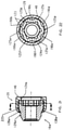
- Fastener 115 generally includes fastener body 116 and cap or shroud 20, which rotates about axis x-x relative to fastener body 116.
- Fastener body 116 includes threaded fastening portion 118, inner tool engaging portion 117, and specially configured outer shroud-retaining portion 119, on which shroud 20 is rotationally and concentrically supported at no more than three annular contact regions.
- fastener body 116 is a specially configured cylindrical member elongated along axis x-x and is generally bounded by rightwardly-facing vertical annular surface 124, outwardly-facing convex surface 125, leftwardly and outwardly-facing frusto-conical surface 128, outwardly-facing horizontal cylindrical surface 129, leftwardly and outwardly-facing frusto-conical surface 130, leftwardly-facing vertical annular surface 131, inwardly-facing horizontal cylindrical surface 132, leftwardly and inwardly-facing frusto-conical surface 133, inwardly-facing horizontal cylindrical surface 134, rightwardly-facing vertical annular surface 135, and inwardly-facing horizontal key patterned cylindrical surface 136.
- Threaded fastening portion 118 of fastener body 116 includes cylindrical bore 121, defined by surface 134, that extends inwardly from the left face 131 of body 116 and is internally threaded over a portion or all of its length.
- Nut fastener 15 may be installed in a wheel hole having an annular recess entrance and a wheel stud or post in the wheel hole, with fastener body 116 and fastening portion 118 1 sized and installed such that the interior threads of inner bore 121 engage the corresponding exterior threads of the wheel stud in the wheel hole.
- Tool engaging portion 117 includes specially configured inner cavity or socket 122, defined by lock patterned surface 136, that extends inwardly from right end face 124 of body 116 and has a specially configured internal profile to which a drive torque may be applied.
- This internal profile comprises a key-receiving pattern that may be implemented as a set of circumferentially spaced internally facing longitudinally extending key-receiving grooves 123 arranged in a lock pattern to which a drive torque may be applied, Such grooves are configured so that a corresponding drive key tool (no shown) may be used to engage lock pattern grooves 123.
- a key having a matching set of key pattern lobes may be used to engage lock pattern grooves 123 to actuate nut fastener 115 about axis x-x.
- Shroud-retaining portion 119 on which shroud 20 is rotationally and concentrically supported, is at the same end of body 116 as tool engaging portion 117.
- Surfaces 124, 125 and 128 generally define shroud-retaining portion 119.
- retaining portion 119 of fastener body 116 comprises outwardly-facing convex surface 125 orientated about axis x-x and axially bounded at one end by step 138, defined by annular surface 128, and axially bounded at the other end by a step defined by annular end surface 124.
- Outer surface 125 has a convex longitudinal profile or shape relative to axis x-x, curving from minimum outside diameter 165 at the left junction with surface 128 and right junction with annular face 124, respectively, to maximum outside diameter 163 at the axial midpoint between such junctions.
- Shroud 20 extends over and around retaining portion 119 of fastener body 116.
- shroud 20 is a specially configured cylindrical member elongated along axis x-x and is generally bounded by rightwardly-facing vertical annular surface 40, outwardly-facing horizontal cylindrical surface 41, leftwardly and outwardly-facing frusto-conical surface 42, outwardly-facing horizontal cylindrical surface 43, leftwardly and outwardly-facing frusto-conical surface 44, leftwardly-facing vertical annular surface 45, inwardly-facing horizontal cylindrical surface 46, leftwardly-facing vertical annular surface 47, and inwardly-facing horizontal cylindrical surface 48.
- shroud 20 includes inner bore 56, defined by surface 47, having uniform inside diameter 64 just slightly larger than the maximum outside diameter 163 of convex surface 125 of fastening portion 119 of body 116.
- shroud 20 has been placed over left distal end 124 of body 116 such that leftwardly-facing annular end face 47 of shroud 20 abuts against rightwardly-facing annular end face 124 of retaining portion 19 of fastener body 116.
- the left thin-walled tubular end 49 of shroud 20 is dimensioned to extend leftwardly a distance beyond step 138 of fastener body 116, defined by the junction of surfaces 125 and 128.
- this extension When assembled as described below, this extension will be reduced in axial length along axis x-x as end portion 49 of shroud 20 deforms and bends or curls inwardly against the sloped surface 128 of step 138 of retaining portion 119 of fastener body 116.
- fastener body 116 and shroud 20 are specially formed such that applying a directed force to rim 49 of shroud 20 causes annular end rim portion 49 of shroud 20 to flare or deform inwards around specially formed step 138 of retaining portion 119 of fastener body 116.
- Shroud 20 is thereby mounted concentrically on retaining portion 119 of fastener 115 such that it does not move axially off of surface 125 of retaining portion 119 but is substantially free to rotate about axis x-x relative to fastener body 116.
- surface 46 of shroud 20 is cylindrical and general configured to align parallel to axis x-x.
- surface 125 of retaining portion 19 of body 16 is convex and spherical relative to axis x-x and surface 46 of shroud 20. It is not parallel.
- the arc radius of surface 125 relative to surface 46 is sized so that there is sufficient clearance around body 116 such that the contact patches between shroud 20 and body 16 are limited to three small annular regions 71, 72 and 73.
- shroud 20 is supported in rotatable relationship with body portion 119 so as to define an annular varying radial gap 160 between shroud inner surface 46 and body outer surface 125 along axially overlapping portion 67. As shown, shroud 20 is thereby is supported in rotatable relationship with body portion 19 at no more than three discrete annular contact regions 70, 71 and 72.
- Contact region 70 is an annular contact region defined by the retaining element of bent rim 49 of shroud 20 against step-down surface 128 of step 138 in body 116.
- Contact region 72 is an annular contact region defined by the retaining element of flange 39 surface 47 of shroud 20 against step-down annular surface 124 of body 116. Intermediate annular contact region 71 is positioned axially between annular contact region 70 and annular contact region 72, at an axial position at which annular varying radial gap 160 is a minimum 161. As shown in FIG. 19 , annular varying radial gap 160 has a cross-sectional area in a plane generally perpendicular to central axis x-x and such cross-section area is not uniform along axially overlapping portion 67, varying from maximum 162 at a first axial position, in this embodiment near step 138 or near end face 124, to minimum 161 at a second axial position.
- Fastener 115a has many of the features of fastener 115 described above in connection with FIGS. 14-19 .
- the significant difference between fastener 115a and fastener 115 lies in the fact that outwardly-facing convex surface 225 of retaining portion 119a includes six longitudinally extending grooves 90a-90f therein equally spaced circumferentially about axis x-x.
- fastening portion 119a of body 116a, on which shroud 20 is rotationally supported is generally bounded by rightwardly-facing vertical annular surface 124a, outwardly-facing convex surface 225, having outwardly-facing longitudinally convex segments 125a-125f and grooves 190a-190f therebetween, and leftwardly and outwardly-facing frusto-conical surface 128a.
- outer surface 225 of retaining portion 119a of fastener body 116a comprises six curvilinear segments 125a-125f equally spaced circumferentially about axis x-x and six grooves 90a-90f extending longitudinally between respective segments 125a-125f.
- Each of segments 125a-125f comprises an outwardly-facing convex or barrel shaped curvilinear surface orientated about axis x-x and axially bounded at one end by step 138a, defined by annular surface 128s, and axially bounded at the other end by a step defined by annular end surface 124a.
- Each of outer segment surfaces 125a-125f curves from a minimum outside diameter at the left junction with surface 128a and the right junction with annular face 124a, respectively, to a maximum outside diameter at the axial midpoint between such junctions.
- Each of grooves 90a-90f extends longitudinally from left surface 128a to right annular face 124a, respectively.
- Each of grooves 90a-90f has a minimum inward radial depth from respective surfaces 125a-125f at the left junction with surface 128a and the right junction with annular face 124a, respectively, and has a maximum inward radial depth from surfaces 125a-125f, respectively, at the axial midpoint between such junctions.
- the components of the embodiments of the fastener may be formed of various different materials.
- steel, stainless steel, brass, aluminum and titanium may be used.
- nonmetallic materials may be used in some applications.
- the cap or shroud may be of a material harder than the lock body.
- the spin cap or shroud may have a hardness range from about 36 Rockwell C to 55 Rockwell C and the lock body may have a hardness less than the hardness of the spin cap. The hardness of the spin cap may be less than about 40 Rockwell C.
Description
- The present invention relates to high security fasteners, and more particularly to a high security fastener having multiple piece or limited contact cap or shroud.
- Locking wheel nuts and wheel bolts are commonly used to attach wheels to axel hub assemblies of automobiles and other vehicles. These fasteners are designed with security features that are intended to thwart theft by rendering the fasteners difficult to remove with conventional tools. In particular, the fasteners do not have the usual hexagonal head pattern found on conventional nuts and bolts and instead have smooth cylindrical sidewalls that cannot be gripped by standard wrenches. Fastener removal requires the use of a special security tool having a unique key pattern that matches a corresponding groove pattern formed in the fastener end face.
- Additional security can be obtained by fitting a free-spinning shroud or cap over the security fasteners cylindrical sidewalls, such that the shroud is in concentric relationship therewith. The shroud discourages the use of theft devices that could otherwise be used to grip the sidewalls and remove the fastener without an authorized security tool. Because the shroud substantially surrounds all exposed surfaces of the sidewalls, no rotational purchase can be obtained in the fastener. The theft device can only engage the shroud, which freely spins under action of the theft device while the main body of the fastener remains stationary.
- Various systems have been developed for rotationally retaining the shroud or spin cap on the fastener body. For example,
U.S. Patent No. 7,445,414 , entitled "High Security Fastener Constructions," is directed to a shroud fastener design having a shroud retaining system for retaining the shroud for rotation relative to the fastener body. International Patent Publication No.WO2004/001237 , entitled "Screw-Threaded Fastening," is directed to a wheel nut having a fastener body and a spin cap or shroud which is retained on the fastener body by means of an outwardly flared end portion of the fastener body which is received within an undercut triangular groove in the inner surface of the cap. - With parenthetical reference to corresponding parts, portions or surfaces of the disclosed embodiment, merely for the purposes of illustration and not by way of limitation, an improved fastener (15, 15a, 15b, 15c, 15d, 15e) is provided comprising : a fastener body (16, 16e) orientated about a central axis (x-x); the fastener body having a tool-engaging portion (17) to which a driving torque may be applied and a threaded fastening portion (18) configured and arranged to mate with a corresponding threaded element; the fastener body having a shroud-receiving body portion (19, 19e) orientated about the central axis; a shroud (20, 20d) concentrically mounted on the shroud-receiving body portion; an intermediate sleeve (50, 50a, 50b, 50c, 50d, 50e) disposed concentrically between the shroud-receiving body portion and the shroud; the shroud having an inner surface (46, 46d) facing an outer surface (54, 54a, 54b, 54c, 54d, 54e) of the intermediate sleeve; the intermediate sleeve having an inner surface (52, 52a, 52b, 52c, 52d, 52e) facing an outer surface (25, 25e) of the shroud-receiving body portion; the shroud being supported in rotatable relationship with the shroud-receiving body portion such that the shroud will rotate relative to the fastener body under an applied external torque prior to the fastener body rotating when the fastener is engaged with an external structure at a design installation torque; a first shroud-retaining element (49) restraining the shroud from movement in at least a first axial direction along the central axis relative to the fastener body; and a second shroud-retaining element (39) restraining the shroud from movement in at least a second axial direction along the central axis opposite to the first axial direction along the central axis relative to the fastener body.
- The outer surface of the intermediate sleeve may have a coefficient of friction less than the outer surface of the shroud-receiving body portion. The inner surface of the intermediate sleeve may have a coefficient of friction less than the outer surface of the shroud-receiving body portion. The outer surface of the intermediate sleeve may have coefficient of friction less than the inner surface of the shroud. The intermediate sleeve may comprise a lubricant-releasing medium or a polymer. The intermediate sleeve may comprise a material selected from a group consisting of a lubricant-impregnated nylon plastic, a lubricant-filled nylon plastic, a polytetrafluoroethylene (PTFE) releasing polymer, a graphite impregnated porous bronze or iron alloy, and a lubricant-impregnated porous bronze or iron alloy.
- The intermediate sleeve may be supported in rotatable relationship with the shroud-receiving body portion and the shroud such that the intermediate sleeve is rotatable about the central axis relative to both the fastener body and the shroud. The fastener body may comprise a lock nut or a lock bolt.
- The fastener may comprise a first sleeve-retaining element (38) restraining the intermediate sleeve from movement in at least a first axial direction along the central axis relative to the fastener body and a second sleeve-retaining element (39) restraining the intermediate sleeve from movement in at least a second axial direction along the central axis opposite to the first axial direction along the central axis relative to the fastener body. The first shroud-retaining element may comprise a surface (28, 28e) of the fastener body and the second shroud-retaining element may comprise a surface (24, 24e) of the fastener body. The first sleeve-retaining element may comprise a surface (26, 26e) of the fastener body and the second sleeve-retaining element may comprise a surface (47, 47d) of the shroud. The first sleeve-retaining element may comprise an annular shoulder (38) of the fastener body facing an opposed annular end (53, 53a, 53b, 53c, 53d, 53e) of the intermediate sleeve. The second sleeve-retaining element may comprise an annular flange (39) of the shroud facing an opposed annular end of the intermediate sleeve (51, 51a, 51b, 51c, 51d, 51e). The first shroud-retaining element may comprise an annular end portion (49, 49d) of the shroud bent inwardly transverse to the central axis and facing an opposed annular step (28, 28d) of the fastener body. The second shroud-retaining element may comprise the annular flange (39) of the shroud facing an opposed annular end (24, 24e) of the fastener body.
- A coefficient of friction between the outer surface of the intermediate sleeve and the inner surface of the shroud may be less than a coefficient of friction between the outer surface of the shroud-receiving body portion and the inner surface of the shroud. The coefficient of friction between the outer surface of the intermediate sleeve and the inner surface of the shroud may be less than about 0.2. The coefficient of friction between the outer surface of the intermediate sleeve and the inner surface of the shroud may be less than about 0.05.
- The inner surface (46, 46d) of the shroud may be not substantially parallel to the outer surface (54, 54c, 54d) of the intermediate sleeve and the inner surface of the intermediate sleeve (52, 52a, 52b, 52d) may be substantially parallel to the outer surface (25) of the shroud-receiving body portion. The inner surface (46) of the shroud may be a substantially cylindrical surface along the axially overlapping portion and the outer surface (54, 54c) of the intermediate sleeve may be a substantially convex curved surface along the axially overlapping portion. The outer surface of the shroud-receiving body portion (25) may be a substantially cylindrical surface along the axially overlapping portion and the inner surface (52b, 52c) of the intermediate sleeve may be a substantially convex curved surface along the axially overlapping portion. The outer surface (54a, 54b, 54d, 54e) of the intermediate sleeve may be a substantially cylindrical surface along the axially overlapping portion and the inner surface (46d) of the shroud may be a substantially convex curved surface along the axially overlapping portion. The inner surface (52, 52a, 52d, 52e) of the intermediate sleeve may be a substantially cylindrical surface along the axially overlapping portion and the outer surface (25e) of the shroud-receiving body portion may be a substantially convex curved surface along the axially overlapping portion.
- In another aspect, a fastener (115, 115a) is provided comprising: a fastener body (116, 116a) orientated about a central axis (x-x); the fastener body having a tool-engaging portion (117) to which a driving torque may be applied and a threaded fastening portion (118) configured and arranged to mate with a corresponding threaded element; the fastener body having a shroud-receiving body portion (119, 119a) orientated about the central axis; a shroud (20) concentrically mounted on the shroud-receiving body portion; a first shroud-retaining element (149) at a first axial position along the central axis restraining the shroud from movement in at least a first axial direction along the central axis relative to the fastener body; a second shroud-retaining element (39) at a second axial position along the central axis restraining the shroud from movement in at least a second axial direction along the central axis opposite to the first axial direction along the central axis relative to the fastener body; the shroud having a shroud inner surface (46) orientated about the central axis facing a body outer surface (125, 225) orientated about the central axis of the shroud-receiving body portion along an axially overlapping portion (67) of the shroud and the fastener body between the first axial position and the second axial position; the shroud being supported relative to the shroud-receiving body portion so as to define an annular varying radial gap (160) between the shroud inner surface and the body outer surface along the axially overlapping portion; and the shroud being supported in rotatable relationship with the shroud-receiving body portion such that the shroud will rotate relative to the fastener body under an applied external torque prior to the fastener body rotating when the fastener is engaged with an external structure at a design installation torque.
- The shroud inner surface is not substantially parallel to the body outer surface along the axially overlapping portion. The shroud inner surface (46) comprises a substantially cylindrical surface along the axially overlapping portion and the body outer surface (125, 125a-f) comprises a convex curved surface along the axially overlapping portion. The shroud may be supported in rotatable relationship with the shroud-receiving body portion at no more than three discrete annular contact regions (70, 70a, 71, 71a, 72, 72a). The annular contact regions may comprise a first annular contact region (70, 70a) defined by the first shroud retaining element, a second annular contact region (72, 72a) defined by the second shroud retaining element, and an intermediate annular contact region (71, 71a) positioned axially between the first annular contact region and the second annular contact region.
- The first shroud-retaining element may comprise an annular end portion (49) of the shroud bent inwardly transverse to the central axis and facing an opposed annular step (128, 128a) of the fastener body. The second shroud-retaining element may comprise an annular flange (39) of the shroud facing an opposed annular end (124, 124a) of the fastener body. The intermediate annular region (71, 71a) may be between the first annular contact region and the second annular contact region at an axial position at which the annular varying radial gap is a minimum (161).
- The shroud inner surface (46) may comprise a substantially cylindrical surface along the axially overlapping portion and the body outer surface (225) may comprise a convex curved surface (125a-f) along the axially overlapping portion having multiple grooves (90a-90f) extending longitudinally therein. The annular varying radial gap may have a cross-sectional area in a plane generally perpendicular to the central axis and the cross-section area may be not uniform along the axially overlapping portion. The cross-section area may vary from a minimum cross-sectional area at a first axial position (161) along the axially overlapping portion to a maximum cross-sectional area (162) at a second axial position along the axially overlapping portion.
-
-
FIG. 1 is a side elevation view of a first embodiment of an improved security fastener. -
FIG. 2 is a right perspective view of the security fastener shown inFIG. 1 . -
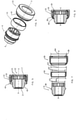
FIG. 3 is a pre-assembled exploded perspective view of the security fastener shown inFIG. 1 . -
FIG. 4 is a pre-assembled exploded longitudinal vertical sectional view of the security fastener shown inFIG. 1 . -
FIG. 5 is a pre-assembled longitudinal vertical sectional view of the security fastener shown inFIG. 1 . -
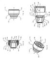
FIG. 6 is a fully-assembled exploded perspective view of the security fastener shown inFIG. 1 . -
FIG. 7 is a fully-assembled exploded longitudinal vertical sectional view of the security fastener shown inFIG. 1 -
FIG. 8 is a fully-assembled longitudinal vertical sectional view of the security fastener shown inFIG. 1 . -
FIG. 9 is a fully-assembled longitudinal vertical sectional view of a second embodiment of the security fastener shown inFIG. 1 . -
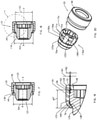
FIG. 10 is a fully-assembled longitudinal vertical sectional view of a third embodiment of the security fastener shown inFIG. 1 . -
FIG. 11 is a fully-assembled longitudinal vertical sectional view of a fourth embodiment of the security fastener shown inFIG. 1 . -
FIG. 12 is a fully-assembled longitudinal vertical sectional view of a fifth embodiment of the security fastener shown inFIG. 1 . -
FIG. 13 is a fully-assembled longitudinal vertical sectional view of a sixth embodiment of the security fastener shown inFIG. 1 . -
FIG. 14 is a side elevation view of a seventh embodiment of an improved security fastener. -
FIG. 15 is a perspective view of the security fastener shown inFIG. 14 . -
FIG. 16 is a pre-assembled exploded longitudinal vertical sectional view of the security fastener shown inFIG. 14 . -
FIG. 17 is a pre-assembled longitudinal vertical sectional view of the security fastener shown inFIG. 14 . -
FIG. 18 is a fully-assembled longitudinal vertical sectional view of the security fastener shown inFIG. 14 . -
FIG. 19 is an enlarged detailed view of the security fastener shown inFIG. 18 , taken generally within the indicated circle A ofFIG. 18 . -
FIG. 20 is a fully-assembled exploded perspective view of an alternative embodiment of the security fastener shown inFIG. 14 . -
FIG. 21 is a transverse vertical sectional view of the security fastener shown inFIG. 20 . -
FIG. 22 is a longitudinal vertical sectional view of the security fastener shown inFIG. 20 . - At the outset, it should be clearly understood that like reference numerals are intended to identify the same structural elements, portions or surfaces consistently throughout the several drawing figures, as such elements, portions or surfaces may be further described or explained by the entire written specification, of which this detailed description is an integral part. Unless otherwise indicated, the drawings are intended to be read (e.g., crosshatching, arrangement of parts, proportion, degree, etc.) together with the specification, and are to be considered a portion of the entire written description of this invention. As used in the following description, the terms "horizontal", "vertical", "left", "right", "up" and "down", as well as adjectival and adverbial derivatives thereof (e.g., "horizontally", "rightwardly", "upwardly", etc.), simply refer to the orientation of the illustrated structure as the particular drawing figure faces the reader. Similarly, the terms "inwardly" and "outwardly" generally refer to the orientation of a surface relative to its axis of elongation, or axis of rotation, as appropriate.
- Referring now to
FIGS. 1-8 , an improved multiple piece safety fastener is provided, a first embodiment of which is generally indicated at 15.Fastener 15 generally includesfastener body 16, cap orshroud 20, which rotates about axis x-x relative tofastener body 16, andintermediate sleeve 50, which is rotatable about axis x-x relative to bothfastener body 16 andshroud 20.Fastener body 16 includes threadedfastening portion 18, innertool engaging portion 17, and outer shroud-retainingportion 19, on whichsleeve 50 andshroud 20 are each rotationally and concentrically supported. - With reference to
FIG. 4 ,fastener body 16 is a specially configured cylindrical member elongated along axis x-x and is generally bounded by rightwardly-facing verticalannular surface 24, outwardly-facing horizontalcylindrical surface 25, rightwardly-facing annularvertical surface 26, outwardly-facing horizontalcylindrical surface 27, leftwardly and outwardly-facing frusto-conical surface 28, outwardly-facing horizontalcylindrical surface 29, leftwardly and outwardly-facing frusto-conical surface 30, leftwardly-facing verticalannular surface 31, inwardly-facing horizontalcylindrical surface 32, leftwardly and inwardly-facing frusto-conical surface 33, inwardly-facing horizontalcylindrical surface 34, rightwardly-facing verticalannular surface 35, and inwardly-facing horizontal key patternedcylindrical surface 36. -
Surfaces fastening portion 18. Threadedfastening portion 18 offastener body 16 includescylindrical bore 21, defined bysurface 34, that extends inwardly from theleft face 31 ofbody 16 and is internally threaded over a portion or all of its length.Nut fastener 15 may be installed in a wheel having a recess hole formed as a relatively deep cylindrical well. The wheel hole has an annular recess entrance and a wheel stud or post in the wheel hole, andfastener body 16 andfastening portion 18 are sized and installed such that the interior threads ofinner bore 21 engage the corresponding exterior threads of the wheel stud in the wheel hole. -
Surfaces tool engaging portion 17.Tool engaging portion 17 offastener body 16 includes specially configured inner cavity orsocket 22, defined by lock patternedsurface 36, that extends inwardly fromright end face 24 ofbody 16 and has a specially configured internal profile to which a drive torque may be applied. This internal profile comprises a key-receiving pattern that may be implemented as a set of circumferentially spaced internally facing longitudinally extending key-receivinggrooves 23 arranged in a lock pattern to which a drive torque may be applied, with the entrance tosocket 22 formed with the key lock pattern. As can be seen, lockpattern grooves 23 are visible on the annular rightfront face 24 oftool engaging portion 17. In order to impart lock pattern uniqueness, lockpattern grooves 23 may be patterned or configured in any suitable alternative manner, such as by employing a selected number of grooves and/or by varying other features thereof, such as the spacing between grooves and/or the width, length, depth, profile or other configuration or feature thereof. Such grooves are configured so that a corresponding drive key tool (no shown) may be used to engagelock pattern grooves 23. The key includes a drive shaft formed with a key pattern that may be implemented as a set of circumferentially arranged key pattern lobes that are configured and arranged to engagelock pattern grooves 23 insocket 22 when the drive shaft is properly aligned and placed inbore 22 ofnut fastener 15. Thus, a key having a matching set of key pattern lobes may be used to engagelock pattern grooves 23 to actuatenut fastener 15 about axis x-x. - The security key is configured to fit within bore 22 to engage the lock pattern and rotate
nut fastener 15. Other tools either will not fit withinbore 22 or will not be able to properly engage and rotatenut fastener 15 when it is installed at its intended design installation torque. The ability ofshroud 20 to spin relative tosleeve 50 andfastener body 16 thereof provides a security feature that protectsfastener 15 from being used as a purchase point for unauthorized tools. Should an attempt be made to rotatefastener 15 by gripping the exposed end,cap 20 will tend to spin without any rotation being imparted tofastener body 16 andfastening portion 18 thereof. - Shroud-retaining
portion 19, on whichsleeve 50 andshroud 20 are each rotationally and concentrically supported, is at the same end ofbody 16 astool engaging portion 17.Surfaces portion 19. As shown, retainingportion 19 offastener body 16 comprisescylindrical surface 25 orientated about axis x-x and axially bounded at one end byshoulder 38, defined byannular surface 26, and axially bounded at the other end by a step defined byannular end surface 24.Cylindrical surface 25 hasouter diameter 61. -
Sleeve 50 extends over and aroundshroud receiving portion 19 and is separately formed fromshroud 20 andfastener body 16. With reference toFIG. 4 ,sleeve 50 is a specially configured cylindrical member elongated along axis x-x and is generally bounded by rightwardly-facing verticalannular surface 51, inwardly-facing horizontalcylindrical surface 52, leftwardly-facing verticalannular surface 53, and outwardly-facingconvex surface 54. As shown,sleeve 50 includesinner bore 55, defined bysurface 52, having uniform insidediameter 62 that is approximately the same size asoutside diameter 61 of retainingportion 19. As shown,outer surface 54 has a convex longitudinal profile or barrel shape relative to axis x-x, curving from minimum outside diameter 65 at leftannular face 53 and rightannular face 51, respectively, to maximum outside diameter 63 at the axial midpoint between leftannular face 53 and rightannular face 51. However,sleeve 50 may have other outside surface profiles. -
Shroud 20 extends over and aroundsleeve 50 and retainingportion 19 offastener body 16. In the pre-assembled state shown inFIG. 4 ,shroud 20 is a specially configured cylindrical member elongated along axis x-x and is generally bounded by rightwardly-facing verticalannular surface 40, outwardly-facing horizontalcylindrical surface 41, leftwardly and outwardly-facing frusto-conical surface 42, outwardly-facing horizontalcylindrical surface 43, leftwardly and outwardly-facing frusto-conical surface 44, leftwardly-facing verticalannular surface 45, inwardly-facing horizontalcylindrical surface 46, leftwardly-facing verticalannular surface 47, and inwardly-facing horizontalcylindrical surface 48. As shown,shroud 20 includesinner bore 56, defined bysurface 47, having uniform insidediameter 64 just slightly larger than the maximum outside diameter 63 ofconvex surface 54 ofsleeve 50. - In the pre-assembled state shown in
FIG. 5 ,sleeve 50 has been placed over leftdistal end 24 ofbody 16 such that leftwardly-facing annular end face 53 ofsleeve 50 abuts against rightwardly-facingannular shoulder surface 26 of retainingportion 19. As shown, in this pre-assembled state,sleeve 50 has an axial width such that rightwardly-facing annular end face 51 ofsleeve 50 is axially to the left of or aligned with rightwardly-facing annular end face 24 of retainingportion 19 offastener body 16. - In this pre-assembled state,
shroud 20 has in turn been placed over leftdistal end 24 ofbody 16 such that the inner annular portion of leftwardly-facingannular surface 47 offlange 39 ofshroud 20 abuts against rightwardly-facing annular end face 24 of retainingportion 19 offastener body 16. As shown, in this pre-assembled state the left thin-walledtubular end 49 ofshroud 20 is dimensioned to extend leftwardly a distance beyondshoulder 38 offastener body 16, defined bysurfaces end portion 49 ofshroud 20 deforms and bends or curls inwardly against the slopedleft surface 28 ofshoulder 38 of retainingportion 19 offastener body 16. - To complete assembly of
fastener 15, withsleeve 50 andshroud 20 placed onfastener body 16 as described above, a rightward and inward axial and radial force is then applied with a ram to surface 44 ofend 49 ofshroud 20 while right inwardly-extendingannular flange 39, defined bysurfaces shroud 20, and end face 24 offastener body 16, are held stationary in a press or the like. Such force is great enough to bend and deform annularend rim portion 49 ofshroud 20 inward againstopposed surfaces fastener body 16, as shown inFIGS. 7 and 8 , which depict the fully assembled configuration offastener 15. Thus,fastener body 16 andshroud 20 are specially formed such that applying a directed force torim 49 ofshroud 20 causes annularend rim portion 49 ofshroud 20 to flare or deform inwards around specially formedshoulder 38 of retainingportion 19 offastener body 16. - When assembled, at least
deformed portion 49 ofshroud 20, which is bent inwardly transverse to central axis x-x, radially overlapsshoulder 38 of retainingportion 19 offastener body 16, thereby retainingshroud 20 from moving axially to the right relative tofastener body 16 such thatshroud 20 is free to rotate about center axis x-x ofbody 16 but is restrained from moving axially to the right off of retainingportion 19 andbody 16. In the other direction,surface 24 of retainingportion 19 ofbody 16 and opposedsurface 47 of inwardly extendingflange 39 ofshroud 20retain shroud 20 such thatshroud 20 is free to rotate about center axis x-x ofbody 16 but is restrained from moving axially to the left. - Regarding
sleeve 50, when assembled as shown inFIG. 8 ,surface 26 ofshoulder 38 of retainingportion 19 offastener body 16 radially overlaps endface 53 ofsleeve 50, thereby retainingsleeve 50 from moving axially to the left relative tofastener body 16 such thatsleeve 50 is free to rotate about center axis x-x ofbody 16 but is restrained from moving axially to the left off of retainingportion 19 andbody 16. Sincebent portion 49 ofshroud 20 radially overlapsshoulder 33 of retainingportion 19 offastener body 16, thereby retainingshroud 20 from moving axially to the right relative tofastener body 16,annular surface 47 offlange 39 ofshroud 20 and opposedsurface 51 ofsleeve 50 retainsleeve 50 such thatsleeve 50 is free to rotate about center axis x-x ofbody 16 but is restrained from moving axially to the right. -
Sleeve 50 andshroud 20 are thereby both mounted concentrically on retainingportion 19 offastener 15 such that neither moves axially off ofsurface 25 of retainingportion 19 but both are substantially free to rotate about axis x-x relative tofastener body 16. - In this embodiment,
fastener body 16 is a unitary formed piece of steel or stainless steel andshroud 20 is a unitary formed piece of steel or stainless steel. In this embodiment,sleeve 50 is a unitary formed piece of material having bearing surfaces 52 and 55 with a coefficient of friction, both static and kinetic, less than the coefficient of friction of either surface 25 offastener body 16 orsurface 46 ofshroud 20. For example,sleeve 50 may be formed of a plastic or polymer material that significantly reduces the coefficient of friction whensleeve 50 rotates relative tofastener body 16 orshroud 20. Iffastener body 16 andshroud 20 are both steel, their direct contact would result in a coefficient of friction of about 0.4 to 0.6 (measured in this embodiment by ASTM G115 standard). With plasticintermediate sleeve 50 betweenfastener body 16 andshroud 20, the coefficient of friction ofshroud 20 relative tobody 16 is reduced to about 0.1 to 0.3.Sleeve 50 may be formed from other materials that provide increased lubricity or the capacity to reduce friction compared to the material offastener body 16 andshroud 20. Atleast surface 54 ofsleeve 50 is lubricious and has a smooth or slippery quality. This may also apply to the innercylindrical surface 52 ofsleeve 50. Accordingly,sleeve 50 reduces the friction betweenfastener body 16 andshroud 20, and limits the cohesive wear or galling betweenfastener body 16 andshroud 20 by providing a mechanical barrier that reduces abrasion and friction. - Other plastic or polymeric materials may be used as alternatives for
sleeve 50, orsleeve 50 may be formed of a lubricant-releasing medium such as an impregnated metal. For example, and without limitation,sleeve 50 may be formed of lubricant-impregnated plastic or polymers, lubricant-filled plastic or polymers, polytetrafluoroethylene (PTFE) releasing plastics or polymers, graphite-impregnated alloys, and or lubricant-impregnated porous alloys such as bronze or iron. When formed of a dry polymer,sleeve 50 may reduce to coefficient of friction betweenshroud 20 andfastener body 16 to between 0.05 and 0.15. Certain lubricant-impregnated alloys, such as oil-impregnated bronze, may further reduce the coefficient of friction betweenshroud 20 andfastener body 16 to between 0.04 and 0.07.Sleeve 50 thereby reduces the friction and wear betweenshroud 20 andfastener body 16. Thus, for example, and without limitation,sleeve 50 may comprise a lubricant-impregnated nylon plastic, a lubricant-filled nylon plastic, a PTFE releasing polymer, a graphite-impregnated porous bronze or iron alloy, or a lubricant-impregnated porous bronze or iron alloy. - If desired,
shroud 20 may comprise a cap have a decorative finish to improve fastener appearance, including, but not limited to, nickel/chrome plating, silver or gray coatings. Furthermore, and without limitation,shroud 20 may be a decorative cap that is made of a material that is different than the material of retainingportion 19. Without limitation, such cap may be plastic, rubber or ceramic or may have a coating that is plastic, rubber, ceramic, anodized or organic. - While applying a single axial force with a ram to exposed
end rim portion 49 of retainingportion 19 whilefastener body 16 andshroud 20 are held stationary in a press has been described, more than a single ramming force may be applied or such force may be applied at various angles relative to axis x-x. - While inwardly extending
flange 39 ofshroud 20 is shown as preformed,flange 39 may be formed during assembly by bending or crimping an end rim ofshroud 20 inwardly with a leftward and inward axial and radial force in a similar manner as described with respect to retainingelement 49. - Turning now to
FIG. 9 , a security fastener 15a according to a second example embodiment is shown. Fastener 15a has many of the features offastener 15 described above in connection withFIGS. 1-8 . The significant difference between fastener 15a andfastener 15 lies in the fact thatsleeve 50a of fastener 15a has an outer cylindrical surface 54a rather than an outer convex surface. As shown, in thisembodiment sleeve 50a is a specially configured cylindrical member elongated along axis x-x and is generally bounded by rightwardly-facing verticalannular surface 51a, inwardly-facing horizontalcylindrical surface 52a, leftwardly-facing vertical annular surface 53a, and outwardly-facing horizontal cylindrical surface 54a. As shown, in this embodiment outer surface 54a has a cylindrical profile or shape relative to axis x-x with a uniform outside diameter along its entire axial length. - Turning now to
FIG. 10 , asecurity fastener 15b according to a third example embodiment is shown.Fastener 15b has many of the features offastener 15 described above in connection withFIGS. 1-8 . The significant difference betweenfastener 15b andfastener 15 lies in the fact thatsleeve 50b offastener 15b has an outer cylindrical surface 54b rather than an outer convex surface and an innercurved surface 52b rather than an inner cylindrical surface. As shown, in thisembodiment sleeve 50b is a specially configured cylindrical member elongated along axis x-x and is generally bounded by rightwardly-facing verticalannular surface 51b, inwardly-facingconvex surface 52b, leftwardly-facing verticalannular surface 53b, and outwardly-facing horizontal cylindrical surface 54b. As shown,inner surface 52b has a convex longitudinal profile or shape, curving from a maximum inside diameter relative to axis x-x at leftannular face 53b and rightannular face 51b, respectively, to a minimum inside diameter relative to axis x-x at the axial midpoint between leftannular face 53b and rightannular face 51b. - Turning now to
FIG. 11 , asecurity fastener 15c according to a third example embodiment is shown.Fastener 15c has many of the features offastener 15 described above in connection withFIGS. 1-8 . The significant difference betweenfastener 15c andfastener 15 lies in the fact thatsleeve 50c offastener 15c has both outer and innercurved surfaces embodiment sleeve 50c is a specially configured cylindrical member elongated along axis x-x and is generally bounded by rightwardly-facing verticalannular surface 51c, inwardly-facingconvex surface 52c, leftwardly-facing verticalannular surface 53c, and outwardly-facingconvex surface 54c. As shown,outer surface 54c has a convex longitudinal profile or shape relative to axis x-x, curving from a minimum outside diameter relative to axis x-x at leftannular face 53c and rightannular face 51c, respectively, to a maximum outside diameter at the axial midpoint between leftannular face 53c and rightannular face 51c. As shown,inner surface 52c has a convex longitudinal profile or shape, curving from a maximum inside diameter relative to axis x-x at leftannular face 53c and rightannular face 51c, respectively, to a minimum inside diameter relative to axis x-x at the axial midpoint between leftannular face 53c and rightannular face 51c. - Turning now to
FIG. 12 , a security fastener 15d according to a fourth example embodiment is shown. Fastener 15d has many of the features offastener 15 described above in connection withFIGS. 1-8 . The significant difference between fastener 15d andfastener 15 lies in the fact thatsleeve 50d of fastener 15d has an outercylindrical surface 54d rather than an outer convex surface andshroud 20d has an inner convex surface 46d rather than an inner cylindrical surface. As shown, in thisembodiment sleeve 50c is a specially configured cylindrical member elongated along axis x-x and is generally bounded by rightwardly-facing verticalannular surface 51c, inwardly-facing horizontalcylindrical surface 52c, leftwardly-facing verticalannular surface 53c, and outwardly-facing horizontalcylindrical surface 54c. As shown, in this embodiment both inner andouter surfaces sleeve 50d have cylindrical profiles or shapes relative to axis x-x with a uniform outside diameter along their entire axial lengths. As shown, in thisembodiment shroud 20d is a specially configured cylindrical member elongated along axis x-x and is generally bounded by rightwardly-facing verticalannular surface 40d, outwardly-facing horizontalcylindrical surface 41d, outwardly-facing frusto-conical surface 42d, outwardly-facingcylindrical surface 43d, which together with leftwardly and outwardly-facing frusto-conical surface 44d and inwardly-facingcylindrical surface 45d, are bent inwardly to form restrainingelement 49d, inwardly-facing convex surface 46d, leftwardly-facing verticalannular surface 47d, and inwardly-facing horizontalcylindrical surface 48d. As shown, inner surface 46d has a convex longitudinal profile or shape, curving from a maximum inside diameter relative to axis x-x at leftannular face 53d and rightannular face 51d, respectively, ofsleeve 50d, to a minimum inside diameter relative to axis x-x at the axial midpoint between leftannular face 53d and rightannular face 51d ofsleeve 50d. - Turning now to
FIG. 13 , asecurity fastener 15e according to a fifth example embodiment is shown.Fastener 15e has many of the features offastener 15 described above in connection withFIGS. 1-8 . The significant difference betweenfastener 15e andfastener 15 lies in the fact thatsleeve 50e offastener 15e has an outercylindrical surface 54e rather than an outer convex surface andfastening portion 19e offastener body 16e has an outer convex surface 25e rather than an outer cylindrical surface. As shown, in thisembodiment sleeve 50e is a specially configured cylindrical member elongated along axis x-x and is generally bounded by rightwardly-facing verticalannular surface 51e, inwardly-facing horizontalcylindrical surface 52e, leftwardly-facing verticalannular surface 53e, and outwardly-facing horizontalcylindrical surface 54e. As shown, in this embodiment both inner andouter surfaces embodiment fastening portion 19e ofbody 16e is generally bounded by rightwardly-facing verticalannular surface 24e, outwardly-facing convex surface 25e, rightwardly-facing annular vertical surface 26e, outwardly-facing horizontalcylindrical surface 27e, and leftwardly and outwardly-facing frusto-conical surface 28e. As shown, outer surface 25e has a convex longitudinal profile or shape relative to axis x-x, curving from a minimum outside diameter relative to axis x-x at leftannular face 53e and rightannular face 51e, respectively, ofsleeve 50e, to a maximum outside diameter at the axial midpoint between leftannular face 53c and rightannular face 51c ofsleeve 50e. - Turning now to
FIGS. 14-19 , asecurity fastener 115 according to a seventh example embodiment is shown.Fastener 115 has many of the features offastener 15 described above in connection withFIGS. 1-8 . The significant difference betweenfastener 115 andfastener 15 lies in the fact thatfastener 115 does not include a separateintermediate sleeve 50. -
Fastener 115 generally includesfastener body 116 and cap orshroud 20, which rotates about axis x-x relative tofastener body 116.Fastener body 116 includes threadedfastening portion 118, innertool engaging portion 117, and specially configured outer shroud-retaining portion 119, on whichshroud 20 is rotationally and concentrically supported at no more than three annular contact regions. - With reference to
FIG. 16 ,fastener body 116 is a specially configured cylindrical member elongated along axis x-x and is generally bounded by rightwardly-facing verticalannular surface 124, outwardly-facingconvex surface 125, leftwardly and outwardly-facing frusto-conical surface 128, outwardly-facing horizontalcylindrical surface 129, leftwardly and outwardly-facing frusto-conical surface 130, leftwardly-facing verticalannular surface 131, inwardly-facing horizontalcylindrical surface 132, leftwardly and inwardly-facing frusto-conical surface 133, inwardly-facing horizontalcylindrical surface 134, rightwardly-facing verticalannular surface 135, and inwardly-facing horizontal key patterned cylindrical surface 136. -
Surfaces fastening portion 118. Threadedfastening portion 118 offastener body 116 includescylindrical bore 121, defined bysurface 134, that extends inwardly from theleft face 131 ofbody 116 and is internally threaded over a portion or all of its length.Nut fastener 15 may be installed in a wheel hole having an annular recess entrance and a wheel stud or post in the wheel hole, withfastener body 116 andfastening portion 118 1 sized and installed such that the interior threads ofinner bore 121 engage the corresponding exterior threads of the wheel stud in the wheel hole. -
Surfaces tool engaging portion 117.Tool engaging portion 117 includes specially configured inner cavity orsocket 122, defined by lock patterned surface 136, that extends inwardly fromright end face 124 ofbody 116 and has a specially configured internal profile to which a drive torque may be applied. This internal profile comprises a key-receiving pattern that may be implemented as a set of circumferentially spaced internally facing longitudinally extending key-receivinggrooves 123 arranged in a lock pattern to which a drive torque may be applied, Such grooves are configured so that a corresponding drive key tool (no shown) may be used to engagelock pattern grooves 123. Thus, a key having a matching set of key pattern lobes may be used to engagelock pattern grooves 123 to actuatenut fastener 115 about axis x-x. - Shroud-retaining portion 119, on which
shroud 20 is rotationally and concentrically supported, is at the same end ofbody 116 astool engaging portion 117.Surfaces fastener body 116 comprises outwardly-facingconvex surface 125 orientated about axis x-x and axially bounded at one end bystep 138, defined byannular surface 128, and axially bounded at the other end by a step defined byannular end surface 124.Outer surface 125 has a convex longitudinal profile or shape relative to axis x-x, curving from minimum outsidediameter 165 at the left junction withsurface 128 and right junction withannular face 124, respectively, to maximum outsidediameter 163 at the axial midpoint between such junctions. -
Shroud 20 extends over and around retaining portion 119 offastener body 116. In the pre-assembled state shown inFIG. 16 ,shroud 20 is a specially configured cylindrical member elongated along axis x-x and is generally bounded by rightwardly-facing verticalannular surface 40, outwardly-facing horizontalcylindrical surface 41, leftwardly and outwardly-facing frusto-conical surface 42, outwardly-facing horizontalcylindrical surface 43, leftwardly and outwardly-facing frusto-conical surface 44, leftwardly-facing verticalannular surface 45, inwardly-facing horizontalcylindrical surface 46, leftwardly-facing verticalannular surface 47, and inwardly-facing horizontalcylindrical surface 48. As shown,shroud 20 includesinner bore 56, defined bysurface 47, having uniform insidediameter 64 just slightly larger than the maximum outsidediameter 163 ofconvex surface 125 of fastening portion 119 ofbody 116. - In the pre-assembled state shown in
FIG. 17 ,shroud 20 has been placed over leftdistal end 124 ofbody 116 such that leftwardly-facing annular end face 47 ofshroud 20 abuts against rightwardly-facingannular end face 124 of retainingportion 19 offastener body 116. As shown, in this pre-assembled state the left thin-walledtubular end 49 ofshroud 20 is dimensioned to extend leftwardly a distance beyondstep 138 offastener body 116, defined by the junction ofsurfaces end portion 49 ofshroud 20 deforms and bends or curls inwardly against the slopedsurface 128 ofstep 138 of retaining portion 119 offastener body 116. - To complete assembly of
fastener 115, withshroud 20 placed onfastener body 116 as described above, a rightward and inward axial and radial force is then applied with a ram to surface 44 ofend 49 ofshroud 20 while right inwardly-extendingannular flange 39, defined bysurfaces shroud 20, and end face 124 offastener body 116, are held stationary in a press or the like. Such force is great enough to bend and deform annularend rim portion 49 ofshroud 20 inward againstopposed surface 128 offastener body 116, as shown inFIGS. 18 and 19 , which depict the fully assembled configuration offastener 115. Thus,fastener body 116 andshroud 20 are specially formed such that applying a directed force torim 49 ofshroud 20 causes annularend rim portion 49 ofshroud 20 to flare or deform inwards around specially formedstep 138 of retaining portion 119 offastener body 116. - When assembled, at least
deformed portion 49 ofshroud 20, which is bent inwardly transverse to central axis x-x, radially overlapsstep 138 of retaining portion 119 offastener body 116, thereby retainingshroud 20 from moving axially to the right relative tofastener body 116 such thatshroud 20 is free to rotate about center axis x-x ofbody 116 but is restrained from moving axially to the right off of retaining portion 119 andbody 116. In the other direction,surface 124 of retaining portion 119 ofbody 116 and opposedsurface 47 ofshroud 20retain shroud 20 such thatshroud 20 is free to rotate about center axis x-x ofbody 116 but is restrained from moving axially to the left. -
Shroud 20 is thereby mounted concentrically on retaining portion 119 offastener 115 such that it does not move axially off ofsurface 125 of retaining portion 119 but is substantially free to rotate about axis x-x relative tofastener body 116. - As shown in
FIG. 19 ,surface 46 ofshroud 20 is cylindrical and general configured to align parallel to axis x-x. In contrast,surface 125 of retainingportion 19 ofbody 16 is convex and spherical relative to axis x-x and surface 46 ofshroud 20. It is not parallel. With this arc relationship, over a given overlapping length, the arc radius ofsurface 125 relative to surface 46 is sized so that there is sufficient clearance aroundbody 116 such that the contact patches betweenshroud 20 andbody 16 are limited to three smallannular regions 71, 72 and 73. Due to the non-parallel orientations ofopposed surfaces portion 67 ofshroud 20 andfastener body 16,shroud 20 is supported in rotatable relationship with body portion 119 so as to define an annular varyingradial gap 160 between shroudinner surface 46 and bodyouter surface 125 along axially overlappingportion 67. As shown,shroud 20 is thereby is supported in rotatable relationship withbody portion 19 at no more than three discreteannular contact regions region 70 is an annular contact region defined by the retaining element ofbent rim 49 ofshroud 20 against step-downsurface 128 ofstep 138 inbody 116. Contactregion 72 is an annular contact region defined by the retaining element offlange 39surface 47 ofshroud 20 against step-downannular surface 124 ofbody 116. Intermediate annular contact region 71 is positioned axially betweenannular contact region 70 andannular contact region 72, at an axial position at which annular varyingradial gap 160 is a minimum 161. As shown inFIG. 19 , annular varyingradial gap 160 has a cross-sectional area in a plane generally perpendicular to central axis x-x and such cross-section area is not uniform along axially overlappingportion 67, varying from maximum 162 at a first axial position, in this embodiment nearstep 138 ornear end face 124, tominimum 161 at a second axial position. - Turning now to
FIGS. 20-22 , a security fastener 115a according to an eighth example embodiment is shown. Fastener 115a has many of the features offastener 115 described above in connection withFIGS. 14-19 . The significant difference between fastener 115a andfastener 115 lies in the fact that outwardly-facingconvex surface 225 of retaining portion 119a includes six longitudinally extending grooves 90a-90f therein equally spaced circumferentially about axis x-x. - As shown, in this embodiment fastening portion 119a of
body 116a, on whichshroud 20 is rotationally supported, is generally bounded by rightwardly-facing vertical annular surface 124a, outwardly-facingconvex surface 225, having outwardly-facing longitudinallyconvex segments 125a-125f andgrooves 190a-190f therebetween, and leftwardly and outwardly-facing frusto-conical surface 128a. As shown,outer surface 225 of retaining portion 119a offastener body 116a comprises sixcurvilinear segments 125a-125f equally spaced circumferentially about axis x-x and six grooves 90a-90f extending longitudinally betweenrespective segments 125a-125f. Each ofsegments 125a-125f comprises an outwardly-facing convex or barrel shaped curvilinear surface orientated about axis x-x and axially bounded at one end bystep 138a, defined by annular surface 128s, and axially bounded at the other end by a step defined by annular end surface 124a. Each ofouter segment surfaces 125a-125f curves from a minimum outside diameter at the left junction with surface 128a and the right junction with annular face 124a, respectively, to a maximum outside diameter at the axial midpoint between such junctions. Each of grooves 90a-90f extends longitudinally from left surface 128a to right annular face 124a, respectively. Each of grooves 90a-90f has a minimum inward radial depth fromrespective surfaces 125a-125f at the left junction with surface 128a and the right junction with annular face 124a, respectively, and has a maximum inward radial depth fromsurfaces 125a-125f, respectively, at the axial midpoint between such junctions. - The components of the embodiments of the fastener may be formed of various different materials. For example, and without limitation, steel, stainless steel, brass, aluminum and titanium may be used. As another alternative, and without limitation, nonmetallic materials may be used in some applications. In some applications, and without limitation, the cap or shroud may be of a material harder than the lock body. For example, and without limitation, the spin cap or shroud may have a hardness range from about 36 Rockwell C to 55 Rockwell C and the lock body may have a hardness less than the hardness of the spin cap. The hardness of the spin cap may be less than about 40 Rockwell C.
- The present invention contemplates that many changes and modifications may be made. Therefore, while forms of the improved fastener have been shown and described, and a number of alternatives discussed, persons skilled in this art will readily appreciate that various additional changes and modifications may be made without departing from the scope of the invention, as defined and differentiated by the following claims.
Claims (15)
- A fastener comprising:a fastener body (16,16e) orientated about a central axis (x-x);said fastener body having a tool-engaging portion (17) to which a driving torque may be applied and a threaded fastening portion (18) configured and arranged to mate with a corresponding threaded element;said fastener body having a shroud-receiving body portion (19,19e) orientated about said central axis;a shroud (20, 20e) concentrically mounted on said shroud-receiving body portion (19, 19e);an intermediate sleeve (50-50e) disposed concentrically between said shroud-receiving body portion (19, 19e) and said shroud (20,20e);said shroud (20,20e) having an inner surface (46,46e) facing an opposed outer surface (54-54e) of said intermediate sleeve (50-50e) along an axially overlapping portion of said shroud and said intermediate sleeve;said intermediate sleeve (50-50e) having an inner surface (52-52e) facing an opposed outer surface (25, 25e) of said shroud-receiving body portion along an axially overlapping portion of said intermediate sleeve and said shroud-receiving body portion;said shroud being supported in rotatable relationship with said shroud-receiving body portion such that said shroud will rotate relative to said fastener body under an applied external torque prior to said fastener body rotating when said fastener is engaged with an external structure at a design installation torque;a first shroud-retaining element (49) restraining said shroud from movement in at least a first axial direction along said central axis relative to said fastener body;a second shroud-retaining element (39) restraining said shroud from movement in at least a second axial direction along said central axis opposite to said first axial direction along said central axis relative to said fastener body; andwherein said outer surface (54) of said intermediate sleeve (50-50e) has a coefficient of friction less than said outer surface (25) of said shroud-receiving body portion (19), and/or said inner surface (52) of said intermediate sleeve has a coefficient of friction less than said outer surface (25) of said shroud-receiving body portion (19), and/or said outer surface (54) of said intermediate sleeve has coefficient of friction less than said inner surface (46) of said shroud.
- The fastener of claims 1 or 9, wherein said intermediate sleeve is supported in rotatable relationship with said shroud-receiving body portion and said shroud such that said intermediate sleeve is rotatable about said central axis relative to both said fastener body and said shroud.
- The fastener of claim 1, wherein said intermediate sleeve comprises a lubricant-releasing medium or a polymer.
- The fastener of claim 3, wherein said intermediate sleeve comprises a material selected from a group consisting of a lubricant-impregnated nylon plastic, a lubricant-filled nylon plastic, a polytetrafluoroethylene (PTFE) releasing polymer, a graphite impregnated porous bronze or iron alloy, and a lubricant-impregnated porous bronze or iron alloy.
- The fastener of claims 1 or 9, comprising a first sleeve-retaining element (38) restraining said intermediate sleeve from movement in at least a first axial direction along said central axis relative to said fastener body and a second sleeve-retaining element (39) restraining said intermediate sleeve from movement in at least a second axial direction along said central axis opposite to said first axial direction along said central axis relative to said fastener body and optionally, said first shroud-retaining element comprises a surface (28, 28e) of said fastener body and said second shroud-retaining element comprises a surface (24, 24e) of said fastener body and said first sleeve-retaining element comprises a surface (26,26e) of said fastener body and said second sleeve-retaining element comprises a surface(47, 47e) of said shroud.
- The fastener of claim 5, wherein said first sleeve-retaining element comprises an annular shoulder (38) of said fastener body facing an opposed annular end (53,53e) of said intermediate sleeve, said second sleeve-retaining element comprises an annular flange (39) of said shroud facing an opposed annular end (51,51e) of said intermediate sleeve, said first shroud-retaining element comprises an annular end portion (49, 49d) of said shroud bent inwardly transverse to said central axis and facing an opposed annular step (28, 28d) of said fastener body and second shroud-retaining element comprises said annular flange (39) of said shroud facing an opposed annular end (24,24e) of said fastener body.
- The fastener set forth in claim 1, wherein a coefficient of friction between said outer surface (54) of said intermediate sleeve and said inner surface (46) of said shroud is less than a coefficient of friction between said outer surface (25) of said shroud-receiving body portion and said inner surface (46) of said shroud.
- The fastener set forth in claim 7, wherein said coefficient of friction between said outer surface (24) of said intermediate sleeve and said inner surface (46) of said shroud is less than about 0.2, and preferably less than about 0.05.
- A fastener comprising:a fastener body (16,16e) orientated about a central axis (x-x);said fastener body having a tool-engaging portion (17) to which a driving torque may be applied and a threaded fastening portion (18) configured and arranged to mate with a corresponding threaded element;said fastener body having a shroud-receiving body portion (19,19e) orientated about said central axis;a shroud (20, 20e) concentrically mounted on said shroud-receiving body portion (19, 19e);an intermediate sleeve (50-50e) disposed concentrically between said shroud-receiving body portion (19, 19e) and said shroud (20,20e);said shroud (20,20e) having an inner surface (46,46e) facing an opposed outer surface (54-54e) of said intermediate sleeve (50-50e) along an axially overlapping portion of said shroud and said intermediate sleeve;said intermediate sleeve (50-50e) having an inner surface (52-52e) facing an opposed outer surface (25, 25e) of said shroud-receiving body portion along an axially overlapping portion of said intermediate sleeve and said shroud-receiving body portion;said shroud being supported in rotatable relationship with said shroud-receiving body portion such that said shroud will rotate relative to said fastener body under an applied external torque prior to said fastener body rotating when said fastener is engaged with an external structure at a design installation torque;a first shroud-retaining element (49) restraining said shroud from movement in at least a first axial direction along said central axis relative to said fastener body;a second shroud-retaining element (39) restraining said shroud from movement in at least a second axial direction along said central axis opposite to said first axial direction along said central axis relative to said fastener body; and,wherein said inner surface (46) of said shroud is a substantially cylindrical surface along said axially overlapping portion and said outer surface (54,54c) of said intermediate sleeve is a substantially convex curved surface along said axially overlapping portion, and/or said outer surface (25) of said shroud-receiving body portion is a substantially cylindrical surface along said axially overlapping portion and said inner surface (46d) of said intermediate sleeve is a substantially convex curved surface along said axially overlapping portion, or said outer surface (54a, 54b, 54d, 54e) of said intermediate sleeve is a substantially cylindrical surface along said axially overlapping portion and said inner surface (46d) of said shroud is a substantially convex curved surface along said axially overlapping portion and/or, said inner surface (52, 52a, 52d, 52e) of said intermediate sleeve is a substantially cylindrical surface along said axially overlapping portion and said outer surface (25e) of said shroud-receiving body portion is a substantially convex curved surface along said axially overlapping portion.
- A fastener comprising:a fastener body (116,116a) orientated about a central axis (x-x);said fastener body having a tool-engaging portion (117) to which a driving torque may be applied and a threaded fastening portion (118) configured and arranged to mate with a corresponding threaded element;said fastener body having a shroud-receiving body portion (119,119a) orientated about said central axis;a shroud (20) concentrically mounted on said shroud-receiving body portion;a first shroud-retaining element (149) at a first axial position along said central axis restraining said shroud from movement in at least a first axial direction along said central axis relative to said fastener body;a second shroud-retaining element (39) at a second axial position along said central axis restraining said shroud from movement in at least a second axial direction along said central axis opposite to said first axial direction along said central axis relative to said fastener body;said shroud having a shroud inner surface (46) orientated about said central axis facing a body outer surface (125,225) orientated about said central axis of said shroud-receiving body portion along an axially overlapping portion (67) of said shroud and said fastener body between said first axial position and said second axial position;said shroud being supported relative to said shroud-receiving body portion so as to define an annular varying longitudinally extending radial gap between said shroud inner surface and said body outer surface longitudinally along said axially overlapping portion;said shroud being supported in rotatable relationship with said shroud-receiving body portion such that said shroud will rotate relative to said fastener body under an applied external torque prior to said fastener body rotating when said fastener is engaged with an external structure at a design installation torque, wherein said shroud inner surface is not substantially parallel to said body outer surface along said axially overlapping portion, and said shroud inner surface comprises a substantially cylindrical surface along said axially overlapping portion and said body outer surface comprises a convex curved surface along said axially overlapping portion.
- The fastener set forth in claim 10, wherein said shroud is supported in rotatable relationship with said shroud-receiving body portion at no more than three discrete annular contact regions (70, 70a, 71, 71a, 72, 72a) and optionally wherein said annular contact regions comprise a first annular contact region (70, 70a) defined by said first shroud retaining element, a second annular contact region (72, 72a) defined by said second shroud retaining element, and an intermediate annular contact region positioned axially between said first annular contact region (70, 70a) and said second annular contact region (72,72a), and further optionally
wherein said intermediate annular contact region (71, 71a) is between said first annular contact region and said second annular contact region at an axial position at which said annular varying radial gap is a minimum (161). - The fastener of claim 10, wherein said first shroud retaining element comprises an annular end portion (49) of said shroud bent inwardly transverse to said central axis and facing an opposed annular step (128,128a) of said fastener body and said second shroud-retaining element comprises an annular flange (39) of said shroud facing an opposed annular end (124,124a) of said fastener body.
- The fastener set forth in claim 10, wherein said wherein said convex curved surface along said axially overlapping portion (225) comprises multiple grooves (190a-190f) extending longitudinally therein.
- The fastener set forth in claim 10, wherein said annular varying radial gap has a cross-sectional area in a plane generally perpendicular to said central axis and said cross-section area is not uniform along said axially overlapping portion, and optionally wherein said cross-section area varies from a minimum cross-sectional area at a first axial position (161) along said axially overlapping portion to a maximum cross-sectional area (162) at a second axial position along said axially overlapping portion.
- The fastener set forth in claim 1, 9 or 10, wherein said fastener body comprises a lock nut or a lock bolt
Applications Claiming Priority (2)
| Application Number | Priority Date | Filing Date | Title |
|---|---|---|---|
| US201762572616P | 2017-10-16 | 2017-10-16 | |
| PCT/US2018/055874 WO2019079178A1 (en) | 2017-10-16 | 2018-10-15 | Multiple piece high security fastener |
Publications (2)
| Publication Number | Publication Date |
|---|---|
| EP3698058A1 EP3698058A1 (en) | 2020-08-26 |
| EP3698058B1 true EP3698058B1 (en) | 2022-03-23 |
Family
ID=64110132
Family Applications (1)
| Application Number | Title | Priority Date | Filing Date |
|---|---|---|---|
| EP18797332.6A Active EP3698058B1 (en) | 2017-10-16 | 2018-10-15 | Multiple piece high security fastener |
Country Status (3)
| Country | Link |
|---|---|
| US (1) | US10962044B2 (en) |
| EP (1) | EP3698058B1 (en) |
| WO (1) | WO2019079178A1 (en) |
Families Citing this family (2)
| Publication number | Priority date | Publication date | Assignee | Title |
|---|---|---|---|---|
| CN112855714B (en) * | 2021-01-01 | 2023-08-01 | 台州道业科技有限公司 | Anti-theft shield for fastener and use method thereof |
| WO2023044037A1 (en) * | 2021-09-16 | 2023-03-23 | Mcgard Llc | High security fastener with drive coupling key |
Citations (1)
| Publication number | Priority date | Publication date | Assignee | Title |
|---|---|---|---|---|
| US7445414B1 (en) * | 2002-03-01 | 2008-11-04 | Mcgard, Llc | High security fastener constructions |
Family Cites Families (16)
| Publication number | Priority date | Publication date | Assignee | Title |
|---|---|---|---|---|
| US2179045A (en) * | 1938-03-03 | 1939-11-07 | Lewis Arthur | Locked pipe closure |
| US4856305A (en) * | 1986-07-28 | 1989-08-15 | Adams Michael W | Office machine security system |
| US4968202A (en) * | 1990-01-16 | 1990-11-06 | Mcgard, Inc. | Decorative and protective cap for locknut |
| US5807048A (en) * | 1992-09-03 | 1998-09-15 | European Atomic Energy Community (Euratom) | Sealing fastener with ultrasonic identifier and removal attempt indicator, and ultrasonic reading device for same |
| DE19609684C2 (en) * | 1996-03-13 | 2000-01-05 | Kellermann Fa Rudolf | Protection ring against contact corrosion |
| US5971848A (en) * | 1998-04-22 | 1999-10-26 | Building Materials Corporation Of America | Plastic ridge vent |
| WO2000058636A1 (en) * | 1999-03-29 | 2000-10-05 | Okamura Yugen Gaisha | Cover device for fastening device |
| US6435791B1 (en) * | 2000-05-19 | 2002-08-20 | Maclean-Fogg Company | Wheel fastener assemblies |
| DE10227251B4 (en) | 2002-06-19 | 2004-05-27 | Diehl Munitionssysteme Gmbh & Co. Kg | Combination antenna for artillery ammunition |
| WO2004001237A1 (en) | 2002-06-20 | 2003-12-31 | Auto Turned Products (Northants) Limited | Screw-threaded fastening |
| US8016535B1 (en) * | 2008-04-28 | 2011-09-13 | Roberts Niels C | Spin lock |
| US8366367B2 (en) * | 2008-12-30 | 2013-02-05 | Brian Matlock | Nut and bolt cover |
| US8888430B2 (en) * | 2012-10-11 | 2014-11-18 | Lazzaro Groppo | Antitheft locking device |
| US9016096B2 (en) * | 2012-12-18 | 2015-04-28 | Dennis Winnie | Locking lug nut system |
| US9689421B2 (en) | 2014-10-09 | 2017-06-27 | Mcgard Llc | High security fastener |
| DE202016104567U1 (en) | 2016-08-19 | 2017-11-21 | Hexlox Ug (Haftungsbeschränkt) | Anti-theft screwdriver |
-
2018
- 2018-10-15 EP EP18797332.6A patent/EP3698058B1/en active Active
- 2018-10-15 WO PCT/US2018/055874 patent/WO2019079178A1/en unknown
- 2018-10-15 US US16/160,365 patent/US10962044B2/en active Active
Patent Citations (1)
| Publication number | Priority date | Publication date | Assignee | Title |
|---|---|---|---|---|
| US7445414B1 (en) * | 2002-03-01 | 2008-11-04 | Mcgard, Llc | High security fastener constructions |
Also Published As
| Publication number | Publication date |
|---|---|
| EP3698058A1 (en) | 2020-08-26 |
| US20190113068A1 (en) | 2019-04-18 |
| WO2019079178A1 (en) | 2019-04-25 |
| US10962044B2 (en) | 2021-03-30 |
Similar Documents
| Publication | Publication Date | Title |
|---|---|---|
| US11339821B2 (en) | High security fastener with external shroud retainer | |
| US7351020B1 (en) | High security fastener constructions | |
| EP3698058B1 (en) | Multiple piece high security fastener | |
| US7445414B1 (en) | High security fastener constructions | |
| US20080044254A1 (en) | Anti-theft fastener assembly | |
| EP3006747B1 (en) | High security fastener | |
| EP1157217A1 (en) | Screw device and assembly for theft-proofing vehicle wheels, and a motor vehicle with such theft-proofing | |
| EP0518969A1 (en) | New and improved bearing assemblies | |
| US20220381285A1 (en) | Decorative security fastener | |
| US20040096289A1 (en) | Fastener assembly | |
| EP3056748B1 (en) | Locking device made as a nut or bolt | |
| WO2023044037A1 (en) | High security fastener with drive coupling key | |
| WO2023167917A1 (en) | Decorative security wheel fastener | |
| WO2020117696A1 (en) | Coil shroud high security fastener | |
| WO2023133147A1 (en) | Decorative security wheel fastener | |
| AU642232B2 (en) | New and improved bearing assemblies |
Legal Events
| Date | Code | Title | Description |
|---|---|---|---|
| STAA | Information on the status of an ep patent application or granted ep patent |
Free format text: STATUS: UNKNOWN |
|
| STAA | Information on the status of an ep patent application or granted ep patent |
Free format text: STATUS: THE INTERNATIONAL PUBLICATION HAS BEEN MADE |
|
| PUAI | Public reference made under article 153(3) epc to a published international application that has entered the european phase |
Free format text: ORIGINAL CODE: 0009012 |
|
| STAA | Information on the status of an ep patent application or granted ep patent |
Free format text: STATUS: REQUEST FOR EXAMINATION WAS MADE |
|
| 17P | Request for examination filed |
Effective date: 20200420 |
|
| AK | Designated contracting states |
Kind code of ref document: A1 Designated state(s): AL AT BE BG CH CY CZ DE DK EE ES FI FR GB GR HR HU IE IS IT LI LT LU LV MC MK MT NL NO PL PT RO RS SE SI SK SM TR |
|
| AX | Request for extension of the european patent |
Extension state: BA ME |
|
| DAV | Request for validation of the european patent (deleted) | ||
| DAX | Request for extension of the european patent (deleted) | ||
| GRAP | Despatch of communication of intention to grant a patent |
Free format text: ORIGINAL CODE: EPIDOSNIGR1 |
|
| STAA | Information on the status of an ep patent application or granted ep patent |
Free format text: STATUS: GRANT OF PATENT IS INTENDED |
|
| INTG | Intention to grant announced |
Effective date: 20210708 |
|
| GRAJ | Information related to disapproval of communication of intention to grant by the applicant or resumption of examination proceedings by the epo deleted |
Free format text: ORIGINAL CODE: EPIDOSDIGR1 |
|
| STAA | Information on the status of an ep patent application or granted ep patent |
Free format text: STATUS: REQUEST FOR EXAMINATION WAS MADE |
|
| INTC | Intention to grant announced (deleted) | ||
| GRAJ | Information related to disapproval of communication of intention to grant by the applicant or resumption of examination proceedings by the epo deleted |
Free format text: ORIGINAL CODE: EPIDOSDIGR1 |
|
| GRAP | Despatch of communication of intention to grant a patent |
Free format text: ORIGINAL CODE: EPIDOSNIGR1 |
|
| GRAP | Despatch of communication of intention to grant a patent |
Free format text: ORIGINAL CODE: EPIDOSNIGR1 |
|
| STAA | Information on the status of an ep patent application or granted ep patent |
Free format text: STATUS: GRANT OF PATENT IS INTENDED |
|
| GRAS | Grant fee paid |
Free format text: ORIGINAL CODE: EPIDOSNIGR3 |
|
| GRAA | (expected) grant |
Free format text: ORIGINAL CODE: 0009210 |
|
| STAA | Information on the status of an ep patent application or granted ep patent |
Free format text: STATUS: THE PATENT HAS BEEN GRANTED |
|
| INTG | Intention to grant announced |
Effective date: 20220201 |
|
| AK | Designated contracting states |
Kind code of ref document: B1 Designated state(s): AL AT BE BG CH CY CZ DE DK EE ES FI FR GB GR HR HU IE IS IT LI LT LU LV MC MK MT NL NO PL PT RO RS SE SI SK SM TR |
|
| REG | Reference to a national code |
Ref country code: GB Ref legal event code: FG4D |
|
| REG | Reference to a national code |
Ref country code: CH Ref legal event code: EP |
|
| REG | Reference to a national code |
Ref country code: IE Ref legal event code: FG4D |
|
| REG | Reference to a national code |
Ref country code: DE Ref legal event code: R096 Ref document number: 602018032689 Country of ref document: DE |
|
| REG | Reference to a national code |
Ref country code: AT Ref legal event code: REF Ref document number: 1477622 Country of ref document: AT Kind code of ref document: T Effective date: 20220415 |
|
| REG | Reference to a national code |
Ref country code: LT Ref legal event code: MG9D |
|
| REG | Reference to a national code |
Ref country code: NL Ref legal event code: MP Effective date: 20220323 |
|
| PG25 | Lapsed in a contracting state [announced via postgrant information from national office to epo] |
Ref country code: SE Free format text: LAPSE BECAUSE OF FAILURE TO SUBMIT A TRANSLATION OF THE DESCRIPTION OR TO PAY THE FEE WITHIN THE PRESCRIBED TIME-LIMIT Effective date: 20220323 Ref country code: RS Free format text: LAPSE BECAUSE OF FAILURE TO SUBMIT A TRANSLATION OF THE DESCRIPTION OR TO PAY THE FEE WITHIN THE PRESCRIBED TIME-LIMIT Effective date: 20220323 Ref country code: NO Free format text: LAPSE BECAUSE OF FAILURE TO SUBMIT A TRANSLATION OF THE DESCRIPTION OR TO PAY THE FEE WITHIN THE PRESCRIBED TIME-LIMIT Effective date: 20220623 Ref country code: LT Free format text: LAPSE BECAUSE OF FAILURE TO SUBMIT A TRANSLATION OF THE DESCRIPTION OR TO PAY THE FEE WITHIN THE PRESCRIBED TIME-LIMIT Effective date: 20220323 Ref country code: HR Free format text: LAPSE BECAUSE OF FAILURE TO SUBMIT A TRANSLATION OF THE DESCRIPTION OR TO PAY THE FEE WITHIN THE PRESCRIBED TIME-LIMIT Effective date: 20220323 Ref country code: BG Free format text: LAPSE BECAUSE OF FAILURE TO SUBMIT A TRANSLATION OF THE DESCRIPTION OR TO PAY THE FEE WITHIN THE PRESCRIBED TIME-LIMIT Effective date: 20220623 |
|
| REG | Reference to a national code |
Ref country code: AT Ref legal event code: MK05 Ref document number: 1477622 Country of ref document: AT Kind code of ref document: T Effective date: 20220323 |
|
| PG25 | Lapsed in a contracting state [announced via postgrant information from national office to epo] |
Ref country code: LV Free format text: LAPSE BECAUSE OF FAILURE TO SUBMIT A TRANSLATION OF THE DESCRIPTION OR TO PAY THE FEE WITHIN THE PRESCRIBED TIME-LIMIT Effective date: 20220323 Ref country code: GR Free format text: LAPSE BECAUSE OF FAILURE TO SUBMIT A TRANSLATION OF THE DESCRIPTION OR TO PAY THE FEE WITHIN THE PRESCRIBED TIME-LIMIT Effective date: 20220624 Ref country code: FI Free format text: LAPSE BECAUSE OF FAILURE TO SUBMIT A TRANSLATION OF THE DESCRIPTION OR TO PAY THE FEE WITHIN THE PRESCRIBED TIME-LIMIT Effective date: 20220323 |
|
| PG25 | Lapsed in a contracting state [announced via postgrant information from national office to epo] |
Ref country code: NL Free format text: LAPSE BECAUSE OF FAILURE TO SUBMIT A TRANSLATION OF THE DESCRIPTION OR TO PAY THE FEE WITHIN THE PRESCRIBED TIME-LIMIT Effective date: 20220323 |
|
| PG25 | Lapsed in a contracting state [announced via postgrant information from national office to epo] |
Ref country code: SM Free format text: LAPSE BECAUSE OF FAILURE TO SUBMIT A TRANSLATION OF THE DESCRIPTION OR TO PAY THE FEE WITHIN THE PRESCRIBED TIME-LIMIT Effective date: 20220323 Ref country code: SK Free format text: LAPSE BECAUSE OF FAILURE TO SUBMIT A TRANSLATION OF THE DESCRIPTION OR TO PAY THE FEE WITHIN THE PRESCRIBED TIME-LIMIT Effective date: 20220323 Ref country code: RO Free format text: LAPSE BECAUSE OF FAILURE TO SUBMIT A TRANSLATION OF THE DESCRIPTION OR TO PAY THE FEE WITHIN THE PRESCRIBED TIME-LIMIT Effective date: 20220323 Ref country code: PT Free format text: LAPSE BECAUSE OF FAILURE TO SUBMIT A TRANSLATION OF THE DESCRIPTION OR TO PAY THE FEE WITHIN THE PRESCRIBED TIME-LIMIT Effective date: 20220725 Ref country code: ES Free format text: LAPSE BECAUSE OF FAILURE TO SUBMIT A TRANSLATION OF THE DESCRIPTION OR TO PAY THE FEE WITHIN THE PRESCRIBED TIME-LIMIT Effective date: 20220323 Ref country code: EE Free format text: LAPSE BECAUSE OF FAILURE TO SUBMIT A TRANSLATION OF THE DESCRIPTION OR TO PAY THE FEE WITHIN THE PRESCRIBED TIME-LIMIT Effective date: 20220323 Ref country code: CZ Free format text: LAPSE BECAUSE OF FAILURE TO SUBMIT A TRANSLATION OF THE DESCRIPTION OR TO PAY THE FEE WITHIN THE PRESCRIBED TIME-LIMIT Effective date: 20220323 Ref country code: AT Free format text: LAPSE BECAUSE OF FAILURE TO SUBMIT A TRANSLATION OF THE DESCRIPTION OR TO PAY THE FEE WITHIN THE PRESCRIBED TIME-LIMIT Effective date: 20220323 |
|
| PG25 | Lapsed in a contracting state [announced via postgrant information from national office to epo] |
Ref country code: PL Free format text: LAPSE BECAUSE OF FAILURE TO SUBMIT A TRANSLATION OF THE DESCRIPTION OR TO PAY THE FEE WITHIN THE PRESCRIBED TIME-LIMIT Effective date: 20220323 Ref country code: IS Free format text: LAPSE BECAUSE OF FAILURE TO SUBMIT A TRANSLATION OF THE DESCRIPTION OR TO PAY THE FEE WITHIN THE PRESCRIBED TIME-LIMIT Effective date: 20220723 Ref country code: AL Free format text: LAPSE BECAUSE OF FAILURE TO SUBMIT A TRANSLATION OF THE DESCRIPTION OR TO PAY THE FEE WITHIN THE PRESCRIBED TIME-LIMIT Effective date: 20220323 |
|
| REG | Reference to a national code |
Ref country code: DE Ref legal event code: R097 Ref document number: 602018032689 Country of ref document: DE |
|
| PLBE | No opposition filed within time limit |
Free format text: ORIGINAL CODE: 0009261 |
|
| STAA | Information on the status of an ep patent application or granted ep patent |
Free format text: STATUS: NO OPPOSITION FILED WITHIN TIME LIMIT |
|
| PG25 | Lapsed in a contracting state [announced via postgrant information from national office to epo] |
Ref country code: DK Free format text: LAPSE BECAUSE OF FAILURE TO SUBMIT A TRANSLATION OF THE DESCRIPTION OR TO PAY THE FEE WITHIN THE PRESCRIBED TIME-LIMIT Effective date: 20220323 |
|
| 26N | No opposition filed |
Effective date: 20230102 |
|
| PG25 | Lapsed in a contracting state [announced via postgrant information from national office to epo] |
Ref country code: SI Free format text: LAPSE BECAUSE OF FAILURE TO SUBMIT A TRANSLATION OF THE DESCRIPTION OR TO PAY THE FEE WITHIN THE PRESCRIBED TIME-LIMIT Effective date: 20220323 Ref country code: MC Free format text: LAPSE BECAUSE OF FAILURE TO SUBMIT A TRANSLATION OF THE DESCRIPTION OR TO PAY THE FEE WITHIN THE PRESCRIBED TIME-LIMIT Effective date: 20220323 |
|
| REG | Reference to a national code |
Ref country code: CH Ref legal event code: PL |
|
| REG | Reference to a national code |
Ref country code: BE Ref legal event code: MM Effective date: 20221031 |
|
| PG25 | Lapsed in a contracting state [announced via postgrant information from national office to epo] |
Ref country code: LU Free format text: LAPSE BECAUSE OF NON-PAYMENT OF DUE FEES Effective date: 20221015 |
|
| PG25 | Lapsed in a contracting state [announced via postgrant information from national office to epo] |
Ref country code: LI Free format text: LAPSE BECAUSE OF NON-PAYMENT OF DUE FEES Effective date: 20221031 Ref country code: FR Free format text: LAPSE BECAUSE OF NON-PAYMENT OF DUE FEES Effective date: 20221031 Ref country code: CH Free format text: LAPSE BECAUSE OF NON-PAYMENT OF DUE FEES Effective date: 20221031 |
|
| PG25 | Lapsed in a contracting state [announced via postgrant information from national office to epo] |
Ref country code: BE Free format text: LAPSE BECAUSE OF NON-PAYMENT OF DUE FEES Effective date: 20221031 |
|
| PG25 | Lapsed in a contracting state [announced via postgrant information from national office to epo] |
Ref country code: IE Free format text: LAPSE BECAUSE OF NON-PAYMENT OF DUE FEES Effective date: 20221015 |
|
| PGFP | Annual fee paid to national office [announced via postgrant information from national office to epo] |
Ref country code: GB Payment date: 20231027 Year of fee payment: 6 |
|
| PGFP | Annual fee paid to national office [announced via postgrant information from national office to epo] |
Ref country code: IT Payment date: 20231023 Year of fee payment: 6 Ref country code: DE Payment date: 20231027 Year of fee payment: 6 |