EP3698058B1 - Mehrteiliges hochsicheres befestigungselement - Google Patents
Mehrteiliges hochsicheres befestigungselement Download PDFInfo
- Publication number
- EP3698058B1 EP3698058B1 EP18797332.6A EP18797332A EP3698058B1 EP 3698058 B1 EP3698058 B1 EP 3698058B1 EP 18797332 A EP18797332 A EP 18797332A EP 3698058 B1 EP3698058 B1 EP 3698058B1
- Authority
- EP
- European Patent Office
- Prior art keywords
- shroud
- fastener
- central axis
- annular
- intermediate sleeve
- Prior art date
- Legal status (The legal status is an assumption and is not a legal conclusion. Google has not performed a legal analysis and makes no representation as to the accuracy of the status listed.)
- Active
Links
Images


Classifications
-
- B—PERFORMING OPERATIONS; TRANSPORTING
- B60—VEHICLES IN GENERAL
- B60B—VEHICLE WHEELS; CASTORS; AXLES FOR WHEELS OR CASTORS; INCREASING WHEEL ADHESION
- B60B3/00—Disc wheels, i.e. wheels with load-supporting disc body
- B60B3/14—Attaching disc body to hub ; Wheel adapters
- B60B3/16—Attaching disc body to hub ; Wheel adapters by bolts or the like
- B60B3/165—Attaching disc body to hub ; Wheel adapters by bolts or the like with locking devices for the fixing means, e.g. screw or nut covers
-
- F—MECHANICAL ENGINEERING; LIGHTING; HEATING; WEAPONS; BLASTING
- F16—ENGINEERING ELEMENTS AND UNITS; GENERAL MEASURES FOR PRODUCING AND MAINTAINING EFFECTIVE FUNCTIONING OF MACHINES OR INSTALLATIONS; THERMAL INSULATION IN GENERAL
- F16B—DEVICES FOR FASTENING OR SECURING CONSTRUCTIONAL ELEMENTS OR MACHINE PARTS TOGETHER, e.g. NAILS, BOLTS, CIRCLIPS, CLAMPS, CLIPS OR WEDGES; JOINTS OR JOINTING
- F16B37/00—Nuts or like thread-engaging members
- F16B37/14—Cap nuts; Nut caps or bolt caps
-
- F—MECHANICAL ENGINEERING; LIGHTING; HEATING; WEAPONS; BLASTING
- F16—ENGINEERING ELEMENTS AND UNITS; GENERAL MEASURES FOR PRODUCING AND MAINTAINING EFFECTIVE FUNCTIONING OF MACHINES OR INSTALLATIONS; THERMAL INSULATION IN GENERAL
- F16B—DEVICES FOR FASTENING OR SECURING CONSTRUCTIONAL ELEMENTS OR MACHINE PARTS TOGETHER, e.g. NAILS, BOLTS, CIRCLIPS, CLAMPS, CLIPS OR WEDGES; JOINTS OR JOINTING
- F16B39/00—Locking of screws, bolts or nuts
- F16B39/02—Locking of screws, bolts or nuts in which the locking takes place after screwing down
- F16B39/025—Locking of screws, bolts or nuts in which the locking takes place after screwing down by plastic deformation of a part of one of the threaded elements into a notch or cavity of the other threaded element
-
- F—MECHANICAL ENGINEERING; LIGHTING; HEATING; WEAPONS; BLASTING
- F16—ENGINEERING ELEMENTS AND UNITS; GENERAL MEASURES FOR PRODUCING AND MAINTAINING EFFECTIVE FUNCTIONING OF MACHINES OR INSTALLATIONS; THERMAL INSULATION IN GENERAL
- F16B—DEVICES FOR FASTENING OR SECURING CONSTRUCTIONAL ELEMENTS OR MACHINE PARTS TOGETHER, e.g. NAILS, BOLTS, CIRCLIPS, CLAMPS, CLIPS OR WEDGES; JOINTS OR JOINTING
- F16B39/00—Locking of screws, bolts or nuts
- F16B39/02—Locking of screws, bolts or nuts in which the locking takes place after screwing down
- F16B39/12—Locking of screws, bolts or nuts in which the locking takes place after screwing down by means of locknuts
-
- F—MECHANICAL ENGINEERING; LIGHTING; HEATING; WEAPONS; BLASTING
- F16—ENGINEERING ELEMENTS AND UNITS; GENERAL MEASURES FOR PRODUCING AND MAINTAINING EFFECTIVE FUNCTIONING OF MACHINES OR INSTALLATIONS; THERMAL INSULATION IN GENERAL
- F16B—DEVICES FOR FASTENING OR SECURING CONSTRUCTIONAL ELEMENTS OR MACHINE PARTS TOGETHER, e.g. NAILS, BOLTS, CIRCLIPS, CLAMPS, CLIPS OR WEDGES; JOINTS OR JOINTING
- F16B41/00—Measures against loss of bolts, nuts, or pins; Measures against unauthorised operation of bolts, nuts or pins
- F16B41/005—Measures against unauthorised operation of bolts, nuts or pins
-
- B—PERFORMING OPERATIONS; TRANSPORTING
- B60—VEHICLES IN GENERAL
- B60B—VEHICLE WHEELS; CASTORS; AXLES FOR WHEELS OR CASTORS; INCREASING WHEEL ADHESION
- B60B2900/00—Purpose of invention
- B60B2900/30—Increase in
- B60B2900/331—Safety or security
- B60B2900/3318—Safety or security by theft prevention
Definitions
- the present invention relates to high security fasteners, and more particularly to a high security fastener having multiple piece or limited contact cap or shroud.
- Locking wheel nuts and wheel bolts are commonly used to attach wheels to axel hub assemblies of automobiles and other vehicles. These fasteners are designed with security features that are intended to thwart theft by rendering the fasteners difficult to remove with conventional tools. In particular, the fasteners do not have the usual hexagonal head pattern found on conventional nuts and bolts and instead have smooth cylindrical sidewalls that cannot be gripped by standard wrenches. Fastener removal requires the use of a special security tool having a unique key pattern that matches a corresponding groove pattern formed in the fastener end face.
- Additional security can be obtained by fitting a free-spinning shroud or cap over the security fasteners cylindrical sidewalls, such that the shroud is in concentric relationship therewith.
- the shroud discourages the use of theft devices that could otherwise be used to grip the sidewalls and remove the fastener without an authorized security tool. Because the shroud substantially surrounds all exposed surfaces of the sidewalls, no rotational purchase can be obtained in the fastener.
- the theft device can only engage the shroud, which freely spins under action of the theft device while the main body of the fastener remains stationary.
- an improved fastener (15, 15a, 15b, 15c, 15d, 15e) comprising : a fastener body (16, 16e) orientated about a central axis (x-x); the fastener body having a tool-engaging portion (17) to which a driving torque may be applied and a threaded fastening portion (18) configured and arranged to mate with a corresponding threaded element; the fastener body having a shroud-receiving body portion (19, 19e) orientated about the central axis; a shroud (20, 20d) concentrically mounted on the shroud-receiving body portion; an intermediate sleeve (50, 50a, 50b, 50c, 50d, 50e) disposed concentrically between the shroud-receiving body portion and the shroud; the shroud having an inner
- the outer surface of the intermediate sleeve may have a coefficient of friction less than the outer surface of the shroud-receiving body portion.
- the inner surface of the intermediate sleeve may have a coefficient of friction less than the outer surface of the shroud-receiving body portion.
- the outer surface of the intermediate sleeve may have coefficient of friction less than the inner surface of the shroud.
- the intermediate sleeve may comprise a lubricant-releasing medium or a polymer.
- the intermediate sleeve may comprise a material selected from a group consisting of a lubricant-impregnated nylon plastic, a lubricant-filled nylon plastic, a polytetrafluoroethylene (PTFE) releasing polymer, a graphite impregnated porous bronze or iron alloy, and a lubricant-impregnated porous bronze or iron alloy.
- a lubricant-impregnated nylon plastic a lubricant-filled nylon plastic
- PTFE polytetrafluoroethylene
- the intermediate sleeve may be supported in rotatable relationship with the shroud-receiving body portion and the shroud such that the intermediate sleeve is rotatable about the central axis relative to both the fastener body and the shroud.
- the fastener body may comprise a lock nut or a lock bolt.
- the fastener may comprise a first sleeve-retaining element (38) restraining the intermediate sleeve from movement in at least a first axial direction along the central axis relative to the fastener body and a second sleeve-retaining element (39) restraining the intermediate sleeve from movement in at least a second axial direction along the central axis opposite to the first axial direction along the central axis relative to the fastener body.
- the first shroud-retaining element may comprise a surface (28, 28e) of the fastener body and the second shroud-retaining element may comprise a surface (24, 24e) of the fastener body.
- the first sleeve-retaining element may comprise a surface (26, 26e) of the fastener body and the second sleeve-retaining element may comprise a surface (47, 47d) of the shroud.
- the first sleeve-retaining element may comprise an annular shoulder (38) of the fastener body facing an opposed annular end (53, 53a, 53b, 53c, 53d, 53e) of the intermediate sleeve.
- the second sleeve-retaining element may comprise an annular flange (39) of the shroud facing an opposed annular end of the intermediate sleeve (51, 51a, 51b, 51c, 51d, 51e).
- the first shroud-retaining element may comprise an annular end portion (49, 49d) of the shroud bent inwardly transverse to the central axis and facing an opposed annular step (28, 28d) of the fastener body.
- the second shroud-retaining element may comprise the annular flange (39) of the shroud facing an opposed annular end (24, 24e) of the fastener body.
- a coefficient of friction between the outer surface of the intermediate sleeve and the inner surface of the shroud may be less than a coefficient of friction between the outer surface of the shroud-receiving body portion and the inner surface of the shroud.
- the coefficient of friction between the outer surface of the intermediate sleeve and the inner surface of the shroud may be less than about 0.2.
- the coefficient of friction between the outer surface of the intermediate sleeve and the inner surface of the shroud may be less than about 0.05.
- the inner surface (46, 46d) of the shroud may be not substantially parallel to the outer surface (54, 54c, 54d) of the intermediate sleeve and the inner surface of the intermediate sleeve (52, 52a, 52b, 52d) may be substantially parallel to the outer surface (25) of the shroud-receiving body portion.
- the inner surface (46) of the shroud may be a substantially cylindrical surface along the axially overlapping portion and the outer surface (54, 54c) of the intermediate sleeve may be a substantially convex curved surface along the axially overlapping portion.
- the outer surface of the shroud-receiving body portion (25) may be a substantially cylindrical surface along the axially overlapping portion and the inner surface (52b, 52c) of the intermediate sleeve may be a substantially convex curved surface along the axially overlapping portion.
- the outer surface (54a, 54b, 54d, 54e) of the intermediate sleeve may be a substantially cylindrical surface along the axially overlapping portion and the inner surface (46d) of the shroud may be a substantially convex curved surface along the axially overlapping portion.
- the inner surface (52, 52a, 52d, 52e) of the intermediate sleeve may be a substantially cylindrical surface along the axially overlapping portion and the outer surface (25e) of the shroud-receiving body portion may be a substantially convex curved surface along the axially overlapping portion.
- a fastener comprising: a fastener body (116, 116a) orientated about a central axis (x-x); the fastener body having a tool-engaging portion (117) to which a driving torque may be applied and a threaded fastening portion (118) configured and arranged to mate with a corresponding threaded element; the fastener body having a shroud-receiving body portion (119, 119a) orientated about the central axis; a shroud (20) concentrically mounted on the shroud-receiving body portion; a first shroud-retaining element (149) at a first axial position along the central axis restraining the shroud from movement in at least a first axial direction along the central axis relative to the fastener body; a second shroud-retaining element (39) at a second axial position along the central axis restraining the shroud from movement
- the shroud inner surface is not substantially parallel to the body outer surface along the axially overlapping portion.
- the shroud inner surface (46) comprises a substantially cylindrical surface along the axially overlapping portion and the body outer surface (125, 125a-f) comprises a convex curved surface along the axially overlapping portion.
- the shroud may be supported in rotatable relationship with the shroud-receiving body portion at no more than three discrete annular contact regions (70, 70a, 71, 71a, 72, 72a).
- the annular contact regions may comprise a first annular contact region (70, 70a) defined by the first shroud retaining element, a second annular contact region (72, 72a) defined by the second shroud retaining element, and an intermediate annular contact region (71, 71a) positioned axially between the first annular contact region and the second annular contact region.
- the first shroud-retaining element may comprise an annular end portion (49) of the shroud bent inwardly transverse to the central axis and facing an opposed annular step (128, 128a) of the fastener body.
- the second shroud-retaining element may comprise an annular flange (39) of the shroud facing an opposed annular end (124, 124a) of the fastener body.
- the intermediate annular region (71, 71a) may be between the first annular contact region and the second annular contact region at an axial position at which the annular varying radial gap is a minimum (161).
- the shroud inner surface (46) may comprise a substantially cylindrical surface along the axially overlapping portion and the body outer surface (225) may comprise a convex curved surface (125a-f) along the axially overlapping portion having multiple grooves (90a-90f) extending longitudinally therein.
- the annular varying radial gap may have a cross-sectional area in a plane generally perpendicular to the central axis and the cross-section area may be not uniform along the axially overlapping portion.
- the cross-section area may vary from a minimum cross-sectional area at a first axial position (161) along the axially overlapping portion to a maximum cross-sectional area (162) at a second axial position along the axially overlapping portion.
- the terms “horizontal”, “vertical”, “left”, “right”, “up” and “down”, as well as adjectival and adverbial derivatives thereof simply refer to the orientation of the illustrated structure as the particular drawing figure faces the reader.
- the terms “inwardly” and “outwardly” generally refer to the orientation of a surface relative to its axis of elongation, or axis of rotation, as appropriate.
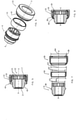
- Fastener 15 generally includes fastener body 16, cap or shroud 20, which rotates about axis x-x relative to fastener body 16, and intermediate sleeve 50, which is rotatable about axis x-x relative to both fastener body 16 and shroud 20.
- Fastener body 16 includes threaded fastening portion 18, inner tool engaging portion 17, and outer shroud-retaining portion 19, on which sleeve 50 and shroud 20 are each rotationally and concentrically supported.
- fastener body 16 is a specially configured cylindrical member elongated along axis x-x and is generally bounded by rightwardly-facing vertical annular surface 24, outwardly-facing horizontal cylindrical surface 25, rightwardly-facing annular vertical surface 26, outwardly-facing horizontal cylindrical surface 27, leftwardly and outwardly-facing frusto-conical surface 28, outwardly-facing horizontal cylindrical surface 29, leftwardly and outwardly-facing frusto-conical surface 30, leftwardly-facing vertical annular surface 31, inwardly-facing horizontal cylindrical surface 32, leftwardly and inwardly-facing frusto-conical surface 33, inwardly-facing horizontal cylindrical surface 34, rightwardly-facing vertical annular surface 35, and inwardly-facing horizontal key patterned cylindrical surface 36.
- Threaded fastening portion 18 of fastener body 16 includes cylindrical bore 21, defined by surface 34, that extends inwardly from the left face 31 of body 16 and is internally threaded over a portion or all of its length.
- Nut fastener 15 may be installed in a wheel having a recess hole formed as a relatively deep cylindrical well. The wheel hole has an annular recess entrance and a wheel stud or post in the wheel hole, and fastener body 16 and fastening portion 18 are sized and installed such that the interior threads of inner bore 21 engage the corresponding exterior threads of the wheel stud in the wheel hole.
- Tool engaging portion 17 of fastener body 16 includes specially configured inner cavity or socket 22, defined by lock patterned surface 36, that extends inwardly from right end face 24 of body 16 and has a specially configured internal profile to which a drive torque may be applied.
- This internal profile comprises a key-receiving pattern that may be implemented as a set of circumferentially spaced internally facing longitudinally extending key-receiving grooves 23 arranged in a lock pattern to which a drive torque may be applied, with the entrance to socket 22 formed with the key lock pattern.
- lock pattern grooves 23 are visible on the annular right front face 24 of tool engaging portion 17.
- lock pattern grooves 23 may be patterned or configured in any suitable alternative manner, such as by employing a selected number of grooves and/or by varying other features thereof, such as the spacing between grooves and/or the width, length, depth, profile or other configuration or feature thereof. Such grooves are configured so that a corresponding drive key tool (no shown) may be used to engage lock pattern grooves 23.
- the key includes a drive shaft formed with a key pattern that may be implemented as a set of circumferentially arranged key pattern lobes that are configured and arranged to engage lock pattern grooves 23 in socket 22 when the drive shaft is properly aligned and placed in bore 22 of nut fastener 15.
- a key having a matching set of key pattern lobes may be used to engage lock pattern grooves 23 to actuate nut fastener 15 about axis x-x.
- the security key is configured to fit within bore 22 to engage the lock pattern and rotate nut fastener 15. Other tools either will not fit within bore 22 or will not be able to properly engage and rotate nut fastener 15 when it is installed at its intended design installation torque.
- shroud 20 to spin relative to sleeve 50 and fastener body 16 thereof provides a security feature that protects fastener 15 from being used as a purchase point for unauthorized tools. Should an attempt be made to rotate fastener 15 by gripping the exposed end, cap 20 will tend to spin without any rotation being imparted to fastener body 16 and fastening portion 18 thereof.
- Surfaces 24, 25, 26, 27 and 28 generally define shroud-retaining portion 19.
- retaining portion 19 of fastener body 16 comprises cylindrical surface 25 orientated about axis x-x and axially bounded at one end by shoulder 38, defined by annular surface 26, and axially bounded at the other end by a step defined by annular end surface 24.
- Cylindrical surface 25 has outer diameter 61.
- Sleeve 50 extends over and around shroud receiving portion 19 and is separately formed from shroud 20 and fastener body 16.
- sleeve 50 is a specially configured cylindrical member elongated along axis x-x and is generally bounded by rightwardly-facing vertical annular surface 51, inwardly-facing horizontal cylindrical surface 52, leftwardly-facing vertical annular surface 53, and outwardly-facing convex surface 54.
- sleeve 50 includes inner bore 55, defined by surface 52, having uniform inside diameter 62 that is approximately the same size as outside diameter 61 of retaining portion 19.
- outer surface 54 has a convex longitudinal profile or barrel shape relative to axis x-x, curving from minimum outside diameter 65 at left annular face 53 and right annular face 51, respectively, to maximum outside diameter 63 at the axial midpoint between left annular face 53 and right annular face 51.
- sleeve 50 may have other outside surface profiles.
- Shroud 20 extends over and around sleeve 50 and retaining portion 19 of fastener body 16.
- shroud 20 is a specially configured cylindrical member elongated along axis x-x and is generally bounded by rightwardly-facing vertical annular surface 40, outwardly-facing horizontal cylindrical surface 41, leftwardly and outwardly-facing frusto-conical surface 42, outwardly-facing horizontal cylindrical surface 43, leftwardly and outwardly-facing frusto-conical surface 44, leftwardly-facing vertical annular surface 45, inwardly-facing horizontal cylindrical surface 46, leftwardly-facing vertical annular surface 47, and inwardly-facing horizontal cylindrical surface 48.
- shroud 20 includes inner bore 56, defined by surface 47, having uniform inside diameter 64 just slightly larger than the maximum outside diameter 63 of convex surface 54 of sleeve 50.
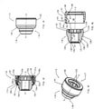
- sleeve 50 has been placed over left distal end 24 of body 16 such that leftwardly-facing annular end face 53 of sleeve 50 abuts against rightwardly-facing annular shoulder surface 26 of retaining portion 19.
- sleeve 50 has an axial width such that rightwardly-facing annular end face 51 of sleeve 50 is axially to the left of or aligned with rightwardly-facing annular end face 24 of retaining portion 19 of fastener body 16.
- shroud 20 has in turn been placed over left distal end 24 of body 16 such that the inner annular portion of leftwardly-facing annular surface 47 of flange 39 of shroud 20 abuts against rightwardly-facing annular end face 24 of retaining portion 19 of fastener body 16.
- the left thin-walled tubular end 49 of shroud 20 is dimensioned to extend leftwardly a distance beyond shoulder 38 of fastener body 16, defined by surfaces 26, 27 and 28.
- this extension When assembled as described below, this extension will be reduced in axial length along axis x-x as end portion 49 of shroud 20 deforms and bends or curls inwardly against the sloped left surface 28 of shoulder 38 of retaining portion 19 of fastener body 16.
- fastener body 16 and shroud 20 are specially formed such that applying a directed force to rim 49 of shroud 20 causes annular end rim portion 49 of shroud 20 to flare or deform inwards around specially formed shoulder 38 of retaining portion 19 of fastener body 16.
- sleeve 50 when assembled as shown in FIG. 8 , surface 26 of shoulder 38 of retaining portion 19 of fastener body 16 radially overlaps end face 53 of sleeve 50, thereby retaining sleeve 50 from moving axially to the left relative to fastener body 16 such that sleeve 50 is free to rotate about center axis x-x of body 16 but is restrained from moving axially to the left off of retaining portion 19 and body 16.
- Sleeve 50 and shroud 20 are thereby both mounted concentrically on retaining portion 19 of fastener 15 such that neither moves axially off of surface 25 of retaining portion 19 but both are substantially free to rotate about axis x-x relative to fastener body 16.
- fastener body 16 is a unitary formed piece of steel or stainless steel and shroud 20 is a unitary formed piece of steel or stainless steel.
- sleeve 50 is a unitary formed piece of material having bearing surfaces 52 and 55 with a coefficient of friction, both static and kinetic, less than the coefficient of friction of either surface 25 of fastener body 16 or surface 46 of shroud 20.
- sleeve 50 may be formed of a plastic or polymer material that significantly reduces the coefficient of friction when sleeve 50 rotates relative to fastener body 16 or shroud 20.
- fastener body 16 and shroud 20 are both steel, their direct contact would result in a coefficient of friction of about 0.4 to 0.6 (measured in this embodiment by ASTM G115 standard).
- Sleeve 50 may be formed from other materials that provide increased lubricity or the capacity to reduce friction compared to the material of fastener body 16 and shroud 20.
- At least surface 54 of sleeve 50 is lubricious and has a smooth or slippery quality. This may also apply to the inner cylindrical surface 52 of sleeve 50. Accordingly, sleeve 50 reduces the friction between fastener body 16 and shroud 20, and limits the cohesive wear or galling between fastener body 16 and shroud 20 by providing a mechanical barrier that reduces abrasion and friction.
- sleeve 50 may be formed of a lubricant-releasing medium such as an impregnated metal.
- sleeve 50 may be formed of lubricant-impregnated plastic or polymers, lubricant-filled plastic or polymers, polytetrafluoroethylene (PTFE) releasing plastics or polymers, graphite-impregnated alloys, and or lubricant-impregnated porous alloys such as bronze or iron.
- PTFE polytetrafluoroethylene
- sleeve 50 may reduce to coefficient of friction between shroud 20 and fastener body 16 to between 0.05 and 0.15.
- lubricant-impregnated alloys such as oil-impregnated bronze, may further reduce the coefficient of friction between shroud 20 and fastener body 16 to between 0.04 and 0.07.
- Sleeve 50 thereby reduces the friction and wear between shroud 20 and fastener body 16.
- sleeve 50 may comprise a lubricant-impregnated nylon plastic, a lubricant-filled nylon plastic, a PTFE releasing polymer, a graphite-impregnated porous bronze or iron alloy, or a lubricant-impregnated porous bronze or iron alloy.
- shroud 20 may comprise a cap have a decorative finish to improve fastener appearance, including, but not limited to, nickel/chrome plating, silver or gray coatings.
- shroud 20 may be a decorative cap that is made of a material that is different than the material of retaining portion 19.
- such cap may be plastic, rubber or ceramic or may have a coating that is plastic, rubber, ceramic, anodized or organic.
- flange 39 of shroud 20 While inwardly extending flange 39 of shroud 20 is shown as preformed, flange 39 may be formed during assembly by bending or crimping an end rim of shroud 20 inwardly with a leftward and inward axial and radial force in a similar manner as described with respect to retaining element 49.
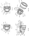
- Fastener 15a has many of the features of fastener 15 described above in connection with FIGS. 1-8 .
- the significant difference between fastener 15a and fastener 15 lies in the fact that sleeve 50a of fastener 15a has an outer cylindrical surface 54a rather than an outer convex surface.
- sleeve 50a is a specially configured cylindrical member elongated along axis x-x and is generally bounded by rightwardly-facing vertical annular surface 51a, inwardly-facing horizontal cylindrical surface 52a, leftwardly-facing vertical annular surface 53a, and outwardly-facing horizontal cylindrical surface 54a.
- outer surface 54a has a cylindrical profile or shape relative to axis x-x with a uniform outside diameter along its entire axial length.
- Fastener 15b has many of the features of fastener 15 described above in connection with FIGS. 1-8 .
- the significant difference between fastener 15b and fastener 15 lies in the fact that sleeve 50b of fastener 15b has an outer cylindrical surface 54b rather than an outer convex surface and an inner curved surface 52b rather than an inner cylindrical surface.
- sleeve 50b is a specially configured cylindrical member elongated along axis x-x and is generally bounded by rightwardly-facing vertical annular surface 51b, inwardly-facing convex surface 52b, leftwardly-facing vertical annular surface 53b, and outwardly-facing horizontal cylindrical surface 54b.
- inner surface 52b has a convex longitudinal profile or shape, curving from a maximum inside diameter relative to axis x-x at left annular face 53b and right annular face 51b, respectively, to a minimum inside diameter relative to axis x-x at the axial midpoint between left annular face 53b and right annular face 51b.
- Fastener 15c has many of the features of fastener 15 described above in connection with FIGS. 1-8 .
- the significant difference between fastener 15c and fastener 15 lies in the fact that sleeve 50c of fastener 15c has both outer and inner curved surfaces 54c and 52c rather than an outer convex surface and an inner cylindrical surface.
- sleeve 50c is a specially configured cylindrical member elongated along axis x-x and is generally bounded by rightwardly-facing vertical annular surface 51c, inwardly-facing convex surface 52c, leftwardly-facing vertical annular surface 53c, and outwardly-facing convex surface 54c.
- outer surface 54c has a convex longitudinal profile or shape relative to axis x-x, curving from a minimum outside diameter relative to axis x-x at left annular face 53c and right annular face 51c, respectively, to a maximum outside diameter at the axial midpoint between left annular face 53c and right annular face 51c.
- inner surface 52c has a convex longitudinal profile or shape, curving from a maximum inside diameter relative to axis x-x at left annular face 53c and right annular face 51c, respectively, to a minimum inside diameter relative to axis x-x at the axial midpoint between left annular face 53c and right annular face 51c.
- Fastener 15d has many of the features of fastener 15 described above in connection with FIGS. 1-8 .
- the significant difference between fastener 15d and fastener 15 lies in the fact that sleeve 50d of fastener 15d has an outer cylindrical surface 54d rather than an outer convex surface and shroud 20d has an inner convex surface 46d rather than an inner cylindrical surface.
- sleeve 50c is a specially configured cylindrical member elongated along axis x-x and is generally bounded by rightwardly-facing vertical annular surface 51c, inwardly-facing horizontal cylindrical surface 52c, leftwardly-facing vertical annular surface 53c, and outwardly-facing horizontal cylindrical surface 54c.
- both inner and outer surfaces 52c and 54c of sleeve 50d have cylindrical profiles or shapes relative to axis x-x with a uniform outside diameter along their entire axial lengths.
- shroud 20d is a specially configured cylindrical member elongated along axis x-x and is generally bounded by rightwardly-facing vertical annular surface 40d, outwardly-facing horizontal cylindrical surface 41d, outwardly-facing frusto-conical surface 42d, outwardly-facing cylindrical surface 43d, which together with leftwardly and outwardly-facing frusto-conical surface 44d and inwardly-facing cylindrical surface 45d, are bent inwardly to form restraining element 49d, inwardly-facing convex surface 46d, leftwardly-facing vertical annular surface 47d, and inwardly-facing horizontal cylindrical surface 48d.
- inner surface 46d has a convex longitudinal profile or shape, curving from a maximum inside diameter relative to axis x-x at left annular face 53d and right annular face 51d, respectively, of sleeve 50d, to a minimum inside diameter relative to axis x-x at the axial midpoint between left annular face 53d and right annular face 51d of sleeve 50d.
- Fastener 15e has many of the features of fastener 15 described above in connection with FIGS. 1-8 .
- the significant difference between fastener 15e and fastener 15 lies in the fact that sleeve 50e of fastener 15e has an outer cylindrical surface 54e rather than an outer convex surface and fastening portion 19e of fastener body 16e has an outer convex surface 25e rather than an outer cylindrical surface.
- sleeve 50e is a specially configured cylindrical member elongated along axis x-x and is generally bounded by rightwardly-facing vertical annular surface 51e, inwardly-facing horizontal cylindrical surface 52e, leftwardly-facing vertical annular surface 53e, and outwardly-facing horizontal cylindrical surface 54e.
- both inner and outer surfaces 52e and 54e have cylindrical profiles or shapes relative to axis x-x with a uniform outside diameter along their entire axial lengths.
- fastening portion 19e of body 16e is generally bounded by rightwardly-facing vertical annular surface 24e, outwardly-facing convex surface 25e, rightwardly-facing annular vertical surface 26e, outwardly-facing horizontal cylindrical surface 27e, and leftwardly and outwardly-facing frusto-conical surface 28e.
- outer surface 25e has a convex longitudinal profile or shape relative to axis x-x, curving from a minimum outside diameter relative to axis x-x at left annular face 53e and right annular face 51e, respectively, of sleeve 50e, to a maximum outside diameter at the axial midpoint between left annular face 53c and right annular face 51c of sleeve 50e.
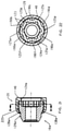
- Fastener 115 has many of the features of fastener 15 described above in connection with FIGS. 1-8 .
- the significant difference between fastener 115 and fastener 15 lies in the fact that fastener 115 does not include a separate intermediate sleeve 50.
- Fastener 115 generally includes fastener body 116 and cap or shroud 20, which rotates about axis x-x relative to fastener body 116.
- Fastener body 116 includes threaded fastening portion 118, inner tool engaging portion 117, and specially configured outer shroud-retaining portion 119, on which shroud 20 is rotationally and concentrically supported at no more than three annular contact regions.
- fastener body 116 is a specially configured cylindrical member elongated along axis x-x and is generally bounded by rightwardly-facing vertical annular surface 124, outwardly-facing convex surface 125, leftwardly and outwardly-facing frusto-conical surface 128, outwardly-facing horizontal cylindrical surface 129, leftwardly and outwardly-facing frusto-conical surface 130, leftwardly-facing vertical annular surface 131, inwardly-facing horizontal cylindrical surface 132, leftwardly and inwardly-facing frusto-conical surface 133, inwardly-facing horizontal cylindrical surface 134, rightwardly-facing vertical annular surface 135, and inwardly-facing horizontal key patterned cylindrical surface 136.
- Threaded fastening portion 118 of fastener body 116 includes cylindrical bore 121, defined by surface 134, that extends inwardly from the left face 131 of body 116 and is internally threaded over a portion or all of its length.
- Nut fastener 15 may be installed in a wheel hole having an annular recess entrance and a wheel stud or post in the wheel hole, with fastener body 116 and fastening portion 118 1 sized and installed such that the interior threads of inner bore 121 engage the corresponding exterior threads of the wheel stud in the wheel hole.
- Tool engaging portion 117 includes specially configured inner cavity or socket 122, defined by lock patterned surface 136, that extends inwardly from right end face 124 of body 116 and has a specially configured internal profile to which a drive torque may be applied.
- This internal profile comprises a key-receiving pattern that may be implemented as a set of circumferentially spaced internally facing longitudinally extending key-receiving grooves 123 arranged in a lock pattern to which a drive torque may be applied, Such grooves are configured so that a corresponding drive key tool (no shown) may be used to engage lock pattern grooves 123.
- a key having a matching set of key pattern lobes may be used to engage lock pattern grooves 123 to actuate nut fastener 115 about axis x-x.
- Shroud-retaining portion 119 on which shroud 20 is rotationally and concentrically supported, is at the same end of body 116 as tool engaging portion 117.
- Surfaces 124, 125 and 128 generally define shroud-retaining portion 119.
- retaining portion 119 of fastener body 116 comprises outwardly-facing convex surface 125 orientated about axis x-x and axially bounded at one end by step 138, defined by annular surface 128, and axially bounded at the other end by a step defined by annular end surface 124.
- Outer surface 125 has a convex longitudinal profile or shape relative to axis x-x, curving from minimum outside diameter 165 at the left junction with surface 128 and right junction with annular face 124, respectively, to maximum outside diameter 163 at the axial midpoint between such junctions.
- Shroud 20 extends over and around retaining portion 119 of fastener body 116.
- shroud 20 is a specially configured cylindrical member elongated along axis x-x and is generally bounded by rightwardly-facing vertical annular surface 40, outwardly-facing horizontal cylindrical surface 41, leftwardly and outwardly-facing frusto-conical surface 42, outwardly-facing horizontal cylindrical surface 43, leftwardly and outwardly-facing frusto-conical surface 44, leftwardly-facing vertical annular surface 45, inwardly-facing horizontal cylindrical surface 46, leftwardly-facing vertical annular surface 47, and inwardly-facing horizontal cylindrical surface 48.
- shroud 20 includes inner bore 56, defined by surface 47, having uniform inside diameter 64 just slightly larger than the maximum outside diameter 163 of convex surface 125 of fastening portion 119 of body 116.
- shroud 20 has been placed over left distal end 124 of body 116 such that leftwardly-facing annular end face 47 of shroud 20 abuts against rightwardly-facing annular end face 124 of retaining portion 19 of fastener body 116.
- the left thin-walled tubular end 49 of shroud 20 is dimensioned to extend leftwardly a distance beyond step 138 of fastener body 116, defined by the junction of surfaces 125 and 128.
- this extension When assembled as described below, this extension will be reduced in axial length along axis x-x as end portion 49 of shroud 20 deforms and bends or curls inwardly against the sloped surface 128 of step 138 of retaining portion 119 of fastener body 116.
- fastener body 116 and shroud 20 are specially formed such that applying a directed force to rim 49 of shroud 20 causes annular end rim portion 49 of shroud 20 to flare or deform inwards around specially formed step 138 of retaining portion 119 of fastener body 116.
- Shroud 20 is thereby mounted concentrically on retaining portion 119 of fastener 115 such that it does not move axially off of surface 125 of retaining portion 119 but is substantially free to rotate about axis x-x relative to fastener body 116.
- surface 46 of shroud 20 is cylindrical and general configured to align parallel to axis x-x.
- surface 125 of retaining portion 19 of body 16 is convex and spherical relative to axis x-x and surface 46 of shroud 20. It is not parallel.
- the arc radius of surface 125 relative to surface 46 is sized so that there is sufficient clearance around body 116 such that the contact patches between shroud 20 and body 16 are limited to three small annular regions 71, 72 and 73.
- shroud 20 is supported in rotatable relationship with body portion 119 so as to define an annular varying radial gap 160 between shroud inner surface 46 and body outer surface 125 along axially overlapping portion 67. As shown, shroud 20 is thereby is supported in rotatable relationship with body portion 19 at no more than three discrete annular contact regions 70, 71 and 72.
- Contact region 70 is an annular contact region defined by the retaining element of bent rim 49 of shroud 20 against step-down surface 128 of step 138 in body 116.
- Contact region 72 is an annular contact region defined by the retaining element of flange 39 surface 47 of shroud 20 against step-down annular surface 124 of body 116. Intermediate annular contact region 71 is positioned axially between annular contact region 70 and annular contact region 72, at an axial position at which annular varying radial gap 160 is a minimum 161. As shown in FIG. 19 , annular varying radial gap 160 has a cross-sectional area in a plane generally perpendicular to central axis x-x and such cross-section area is not uniform along axially overlapping portion 67, varying from maximum 162 at a first axial position, in this embodiment near step 138 or near end face 124, to minimum 161 at a second axial position.
- Fastener 115a has many of the features of fastener 115 described above in connection with FIGS. 14-19 .
- the significant difference between fastener 115a and fastener 115 lies in the fact that outwardly-facing convex surface 225 of retaining portion 119a includes six longitudinally extending grooves 90a-90f therein equally spaced circumferentially about axis x-x.
- fastening portion 119a of body 116a, on which shroud 20 is rotationally supported is generally bounded by rightwardly-facing vertical annular surface 124a, outwardly-facing convex surface 225, having outwardly-facing longitudinally convex segments 125a-125f and grooves 190a-190f therebetween, and leftwardly and outwardly-facing frusto-conical surface 128a.
- outer surface 225 of retaining portion 119a of fastener body 116a comprises six curvilinear segments 125a-125f equally spaced circumferentially about axis x-x and six grooves 90a-90f extending longitudinally between respective segments 125a-125f.
- Each of segments 125a-125f comprises an outwardly-facing convex or barrel shaped curvilinear surface orientated about axis x-x and axially bounded at one end by step 138a, defined by annular surface 128s, and axially bounded at the other end by a step defined by annular end surface 124a.
- Each of outer segment surfaces 125a-125f curves from a minimum outside diameter at the left junction with surface 128a and the right junction with annular face 124a, respectively, to a maximum outside diameter at the axial midpoint between such junctions.
- Each of grooves 90a-90f extends longitudinally from left surface 128a to right annular face 124a, respectively.
- Each of grooves 90a-90f has a minimum inward radial depth from respective surfaces 125a-125f at the left junction with surface 128a and the right junction with annular face 124a, respectively, and has a maximum inward radial depth from surfaces 125a-125f, respectively, at the axial midpoint between such junctions.
- the components of the embodiments of the fastener may be formed of various different materials.
- steel, stainless steel, brass, aluminum and titanium may be used.
- nonmetallic materials may be used in some applications.
- the cap or shroud may be of a material harder than the lock body.
- the spin cap or shroud may have a hardness range from about 36 Rockwell C to 55 Rockwell C and the lock body may have a hardness less than the hardness of the spin cap. The hardness of the spin cap may be less than about 40 Rockwell C.
Landscapes
- Engineering & Computer Science (AREA)
- General Engineering & Computer Science (AREA)
- Mechanical Engineering (AREA)
- Insertion Pins And Rivets (AREA)
- Details Of Spanners, Wrenches, And Screw Drivers And Accessories (AREA)
Claims (15)
- Befestigungselement, Folgendes umfassend:einen Befestigungselementkörper (16, 16e), der um eine Mittelachse (x-x) angeordnet ist;wobei der Befestigungselementkörper einen Werkzeugeingriffsabschnitt (17), auf den ein Drehmoment aufgebracht werden kann, und einen Gewindebefestigungsabschnitt (18), der dazu ausgelegt ist, sich mit einem zugehörigen Gewindeelement zu verbinden, aufweist;wobei der Befestigungselementkörper einen ummantelungsaufnehmenden Körperabschnitt (19, 19e) aufweist, der um die Mittelachse angeordnet ist;eine Ummantelung (20, 20e), die konzentrisch am ummantelungsaufnehmenden Körperabschnitt (19, 19e) montiert ist;eine Zwischenhülse (50-50e), die konzentrisch zwischen dem ummantelungsaufnehmenden Körperabschnitt (19, 19e) und der Ummantelung (20, 20e) angeordnet ist;wobei die Ummantelung (20, 20e) eine Innenfläche (46, 46e) aufweist, die einer entgegengesetzten Außenfläche (54-54e) der Zwischenhülse (50-50e) entlang eines axial überlagernden Abschnitts der Ummantelung und der Zwischenhülse zugewandt ist;wobei die Zwischenhülse (50-50e) eine Innenfläche (52-52e) aufweist, die einer entgegengesetzten Außenfläche (25, 25e) des ummantelungsaufnehmenden Körperabschnitts entlang eines axial überlagernden Abschnitts der Zwischenhülse und des ummantelungsaufnehmenden Körperabschnitts zugewandt ist;wobei die Ummantelung in einem drehbaren Verhältnis mit dem ummantelungsaufnehmenden Körperabschnitt gelagert ist, sodass sich die Ummantelung in Bezug zu dem Befestigungselementkörper unter einem von außen aufgebrachten Drehmoment dreht, bevor sich der Befestigungselementkörper dreht, wenn das Befestigungselement mit einem festgelegten Anzugsdrehmoment in eine äußere Struktur eingreift;ein erstes Ummantelungshalteelement (49), das die Ummantelung an einer Bewegung in zumindest eine erste Axialrichtung entlang der Mittelachse in Bezug zum Befestigungselementkörper hindert;ein zweites Ummantelungshalteelement (39), das die Ummantelung an einer Bewegung in zumindest eine zweite Axialrichtung entlang der Mittelachse, die der ersten Axialrichtung entlang der Mittelachse entgegengesetzt ist, in Bezug zum Befestigungselementkörper hindert; undwobei die Außenfläche (54) der Zwischenhülse (50-50e) einen Reibungskoeffizienten aufweist, der kleiner ist als der der Außenfläche (25) des ummantelungsaufnehmenden Körperabschnitts (19), und/oder wobei die Innenfläche (52) der Zwischenhülse einen Reibungskoeffizienten aufweist, der kleiner ist als der der Außenfläche (25) des ummantelungsaufnehmenden Körperabschnitts (19), und/oder wobei die Außenfläche (54) der Zwischenhülse einen Reibungskoeffizienten aufweist, der kleiner ist als der der Innenfläche (46) der Ummantelung.
- Befestigungselement nach Ansprüchen 1 oder 9, wobei die Zwischenhülse in einem drehbaren Verhältnis mit dem ummantelungsaufnehmenden Körperabschnitt und der Ummantelung gelagert ist, sodass die Zwischenhülse in Bezug zu sowohl dem Befestigungselementkörper als auch der Ummantelung um die Mittelachse drehbar ist.
- Befestigungselement nach Anspruch 1, wobei die Zwischenhülse ein schmiermittelabgebendes Medium oder ein Polymer umfasst.
- Befestigungselement nach Anspruch 3, wobei die Zwischenhülse ein Material umfasst, das aus einer Gruppe bestehend aus einem schmiermittelgetränkten Nylonkunststoff, einem schmiermittelgefüllten Nylonkunststoff, einem Polytetrafluorethylen (PTFE) freisetzenden Polymer, einer graphitgetränkten porösen Bronze- oder Eisenlegierung und einer schmiermittelgetränkten porösen Bronze- oder Eisenlegierung ausgewählt ist.
- Befestigungselement nach Ansprüchen 1 oder 9, ein erstes Hülsenhalteelement (38), das die Zwischenhülse an einer Bewegung in zumindest eine erste Axialrichtung entlang der Mittelachse in Bezug zum Befestigungselementkörper hindert, und ein zweites Hülsenhalteelement (39), das die Zwischenhülse an einer Bewegung in zumindest eine zweite Axialrichtung entlang der Mittelachse, die der ersten Axialrichtung entlang der Mittelachse entgegengesetzt ist, in Bezug zum Befestigungselementkörper hindert, umfassend, und optional wobei das erste Ummantelungshalteelement eine Fläche (28, 28e) des Befestigungselementkörpers umfasst und das zweite Ummantelungshalteelement eine Fläche (24, 24e) des Befestigungselementkörpers umfasst und das erste Hülsenhalteelement eine Fläche (26, 26e) des Befestigungselementkörpers umfasst und das zweite Hülsenhalteelement eine Fläche (47, 47e) der Ummantelung umfasst.
- Befestigungselement nach Anspruch 5, wobei das erste Hülsenhalteelement eine ringförmige Schulter (38) des Befestigungselementkörpers umfasst, das einem entgegengesetzten ringförmigen Ende (53, 53e) der Zwischenhülse zugewandt ist, wobei das zweite Hülsenhalteelement einen ringförmigen Flansch (39) der Ummantelung umfasst, der einem entgegengesetzten ringförmigen Ende (51, 51e) der Zwischenhülse zugewandt ist, wobei das erste Ummantelungshalteelement einen ringförmigen Endabschnitt (49, 49d) der Ummantelung umfasst, der quer zur Mittelachse nach innen gekrümmt ist und einer entgegengesetzten ringförmigen Stufe (28, 28d) des Befestigungselementkörpers zugewandt ist, und wobei das zweite Ummantelungshalteelement den ringförmigen Flansch (39) der Ummantelung umfasst, der einem entgegengesetzten ringförmigen Ende (24, 24e) des Befestigungselementkörpers zugewandt ist.
- Befestigungselement nach Anspruch 1, wobei ein Reibungskoeffizient zwischen der Außenfläche (54) der Zwischenhülse und der Innenfläche (46) der Ummantelung kleiner als ein Reibungskoeffizient zwischen der Außenfläche (25) des ummantelungsaufnehmenden Körperabschnitts und der Innenfläche (46) der Ummantelung ist.
- Befestigungselement nach Anspruch 7, wobei der Reibungskoeffizient zwischen der Außenfläche (24) der Zwischenhülse und der Innenfläche (46) der Ummantelung kleiner als etwa 0,2 und vorzugsweise kleiner als etwa 0,05 ist.
- Befestigungselement, Folgendes umfassend:einen Befestigungselementkörper (16, 16e), der um eine Mittelachse (x-x) angeordnet ist;wobei der Befestigungselementkörper einen Werkzeugeingriffsabschnitt (17), auf den ein Drehmoment aufgebracht werden kann, und einen Gewindebefestigungsabschnitt (18), der dazu ausgelegt ist, sich mit einem zugehörigen Gewindeelement zu verbinden, aufweist;wobei der Befestigungselementkörper einen ummantelungsaufnehmenden Körperabschnitt (19, 19e) aufweist, der um die Mittelachse angeordnet ist;eine Ummantelung (20, 20e), die konzentrisch am ummantelungsaufnehmenden Körperabschnitt (19, 19e) montiert ist;eine Zwischenhülse (50-50e), die konzentrisch zwischen dem ummantelungsaufnehmenden Körperabschnitt (19, 19e) und der Ummantelung (20, 20e) angeordnet ist;wobei die Ummantelung (20, 20e) eine Innenfläche (46, 46e) aufweist, die einer entgegengesetzten Außenfläche (54-54e) der Zwischenhülse (50-50e) entlang eines axial überlagernden Abschnitts der Ummantelung und der Zwischenhülse zugewandt ist;wobei die Zwischenhülse (50-50e) eine Innenfläche (52-52e) aufweist, die einer entgegengesetzten Außenfläche (25, 25e) des ummantelungsaufnehmenden Körperabschnitts entlang eines axial überlagernden Abschnitts der Zwischenhülse und des ummantelungsaufnehmenden Körperabschnitts zugewandt ist;wobei die Ummantelung in einem drehbaren Verhältnis mit dem ummantelungsaufnehmenden Körperabschnitt gelagert ist, sodass sich die Ummantelung in Bezug zu dem Befestigungselementkörper unter einem von außen aufgebrachten Drehmoment dreht, bevor sich der Befestigungselementkörper dreht, wenn das Befestigungselement mit einem festgelegten Anzugsdrehmoment in eine äußere Struktur eingreift;ein erstes Ummantelungshalteelement (49), das die Ummantelung an einer Bewegung in zumindest eine erste Axialrichtung entlang der Mittelachse in Bezug zum Befestigungselementkörper hindert;ein zweites Ummantelungshalteelement (39), das die Ummantelung an einer Bewegung in zumindest eine zweite Axialrichtung entlang der Mittelachse, die der ersten Axialrichtung entlang der Mittelachse entgegengesetzt ist, in Bezug zum Befestigungselementkörper hindert; undwobei die Innenfläche (46) der Ummantelung eine im Wesentlichen zylindrische Fläche entlang des axial überlagernden Abschnitts ist und die Außenfläche (54, 54c) der Zwischenhülse eine im Wesentlichen konvex gekrümmte Fläche entlang des axial überlagernden Abschnitts ist und/oder wobei die Außenfläche (25) des ummantelungsaufnehmenden Körperabschnitts eine im Wesentlichen zylindrische Fläche entlang des axial überlagernden Abschnitts ist und die Innenfläche (46d) der Zwischenhülse eine im Wesentlichen konvex gekrümmte Fläche entlang des axial überlagernden Abschnitts ist oder die Außenfläche (54a, 54b, 54d, 54e) der Zwischenhülse eine im Wesentlichen zylindrische Fläche entlang des axial überlagernden Abschnitts ist und die Innenfläche (46d) der Ummantelung eine im Wesentlichen konvex gekrümmte Fläche entlang des axial überlagernden Abschnitts ist und/oder die Innenfläche (52, 52a, 52d, 52e) der Zwischenhülse eine im Wesentlichen zylindrische Fläche entlang des axial überlagernden Abschnitts ist und die Außenfläche (25e) des ummantelungsaufnehmenden Körperabschnitts eine im Wesentlichen konvex gekrümmte Fläche entlang des axial überlagernden Abschnitts ist.
- Befestigungselement, Folgendes umfassend:einen Befestigungselementkörper (116, 116a), der um eine Mittelachse (x-x) angeordnet ist;wobei der Befestigungselementkörper einen Werkzeugeingriffsabschnitt (117), auf den ein Drehmoment aufgebracht werden kann, und einen Gewindebefestigungsabschnitt (118), der dazu ausgelegt ist, sich mit einem zugehörigen Gewindeelement zu verbinden, aufweist;wobei der Befestigungselementkörper einen ummantelungsaufnehmenden Körperabschnitt (119, 119a) aufweist, der um die Mittelachse angeordnet ist;eine Ummantelung (20), die konzentrisch am ummantelungsaufnehmenden Körperabschnitt montiert ist;ein erstes Ummantelungshalteelement (149) an einer ersten Axialstellung entlang der Mittelachse, das die Ummantelung an einer Bewegung in zumindest eine erste Axialrichtung entlang der Mittelachse in Bezug zum Befestigungselementkörper hindert;ein zweites Ummantelungshalteelement (39) an einer zweiten Axialstellung entlang der Mittelachse, das die Ummantelung an einer Bewegung in zumindest eine zweite Axialrichtung entlang der Mittelachse, die der ersten Axialrichtung entlang der Mittelachse entgegengesetzt ist, in Bezug zum Befestigungselementkörper hindert;wobei die Ummantelung eine Ummantelungsinnenfläche (46) aufweist, die um die Mittelachse ausgerichtet ist und einer Körperaußenfläche (125, 225) zugewandt ist, die um die Mittelachse des ummantelungsaufnehmenden Körperabschnitts entlang eines axial überlagernden Abschnitts (67) der Ummantelung und des Befestigungselementkörpers zwischen der ersten Axialstellung und der zweiten Axialstellung ausgerichtet ist;wobei die Ummantelung in Bezug zum ummantelungsaufnehmenden Körperabschnitt gelagert wird, um einen ringförmig variierenden, sich in Längsrichtung erstreckenden, radialen Spalt zwischen der Ummantelungsinnenfläche und der Körperaußenfläche in Längsrichtung entlang des axial überlagernden Abschnitts zu definieren;wobei die Ummantelung in einem drehbaren Verhältnis mit dem ummantelungsaufnehmenden Körperabschnitt gelagert ist, sodass sich die Ummantelung in Bezug zu dem Befestigungselementkörper unter einem von außen aufgebrachten Drehmoment dreht, bevor sich der Befestigungselementkörper dreht, wenn das Befestigungselement mit einem festgelegten Anzugsdrehmoment in eine äußere Struktur eingreift, wobei die Ummantelungsinnenfläche nicht im Wesentlichen parallel zur Körperaußenfläche entlang des axial überlagernden Abschnitts ist und die Ummantelungsinnenfläche eine im Wesentlichen zylindrische Fläche entlang des axial überlagernden Abschnitts umfasst und die Körperaußenfläche eine konvex gekrümmte Fläche entlang des axial überlagernden Abschnitts umfasst.
- Befestigungselement nach Anspruch 10, wobei die Ummantelung in einem drehbaren Verhältnis mit dem ummantelungsaufnehmenden Körperabschnitt an maximal drei einzelnen ringförmigen Kontaktbereichen (70, 70a, 71, 71a, 72, 72a) gelagert wird und optional wobei die ringförmigen Kontaktbereiche einen ersten ringförmigen Kontaktbereich (70, 70a), der durch das erste Ummantelungshalteelement definiert wird, einen zweiten ringförmigen Kontaktbereich (72, 72a), der durch das zweite Ummantelungshalteelement definiert wird, und einen ringförmigen Zwischenkontaktbereich, der axial zwischen dem ersten ringförmigen Kontaktbereich (70, 70a) und dem zweiten ringförmigen Kontaktbereich (72, 72a) angeordnet ist, umfassen, und ferner optional wobei der ringförmige Zwischenkontaktbereich (71, 71a) zwischen dem ersten ringförmigen Kontaktbereich und dem zweiten ringförmigen Kontaktbereich an einer Axialstellung liegt, an der der ringförmige, variierende, radiale Spalt (161) minimal ist.
- Befestigungselement nach Anspruch 10, wobei das erste Ummantelungshalteelement einen ringförmigen Endabschnitt (49) der Ummantelung umfasst, der quer zur Mittelachse nach innen gekrümmt ist und einer entgegengesetzten ringförmigen Stufe (128, 128a) des Befestigungselementkörpers zugewandt ist, und wobei das zweite Ummantelungshalteelement einen ringförmigen Flansch (39) der Ummantelung umfasst, der einem entgegengesetzten ringförmigen Ende (124, 124a) des Befestigungselementkörpers zugewandt ist.
- Befestigungselement nach Anspruch 10, wobei die konvex gekrümmte Fläche entlang des axial überlagernden Abschnitts (225) mehrere Nuten (190a-190f) umfasst, die sich in Längsrichtung darin erstrecken.
- Befestigungselement nach Anspruch 10, wobei der ringförmige, variierende, radiale Spalt eine Querschnittsfläche in einer Ebene aufweist, die im Allgemeinen senkrecht zur Mittelachse verläuft, und wobei die Querschnittsfläche entlang des axial überlagernden Abschnitts nicht gleichförmig verläuft und optional wobei die Querschnittsfläche von einer minimalen Querschnittsfläche an einer ersten Axialstellung (161) entlang des axial überlagernden Abschnitts zu einer maximalen Querschnittsfläche (162) an einer zweiten Axialstellung entlang des axial überlagernden Abschnitts variiert.
- Befestigungselement nach Anspruch 1, 9 oder 10, wobei der Befestigungselementkörper eine Sicherungsmutter oder einen Verriegelungsbolzen umfasst.
Applications Claiming Priority (2)
| Application Number | Priority Date | Filing Date | Title |
|---|---|---|---|
| US201762572616P | 2017-10-16 | 2017-10-16 | |
| PCT/US2018/055874 WO2019079178A1 (en) | 2017-10-16 | 2018-10-15 | MULTI-PIECE HIGH SECURITY FASTENING ELEMENT |
Publications (2)
| Publication Number | Publication Date |
|---|---|
| EP3698058A1 EP3698058A1 (de) | 2020-08-26 |
| EP3698058B1 true EP3698058B1 (de) | 2022-03-23 |
Family
ID=64110132
Family Applications (1)
| Application Number | Title | Priority Date | Filing Date |
|---|---|---|---|
| EP18797332.6A Active EP3698058B1 (de) | 2017-10-16 | 2018-10-15 | Mehrteiliges hochsicheres befestigungselement |
Country Status (3)
| Country | Link |
|---|---|
| US (1) | US10962044B2 (de) |
| EP (1) | EP3698058B1 (de) |
| WO (1) | WO2019079178A1 (de) |
Families Citing this family (3)
| Publication number | Priority date | Publication date | Assignee | Title |
|---|---|---|---|---|
| CN112855714B (zh) * | 2021-01-01 | 2023-08-01 | 台州道业科技有限公司 | 一种紧固件防盗护罩及其使用方法 |
| EP4402388B1 (de) * | 2021-09-16 | 2026-02-04 | McGard LLC | Hochsicheres befestigungselement mit antriebskupplungsschlüssel |
| WO2024206208A1 (en) * | 2023-03-31 | 2024-10-03 | Mcgard Llc | Fastener and cap assembly |
Citations (1)
| Publication number | Priority date | Publication date | Assignee | Title |
|---|---|---|---|---|
| US7445414B1 (en) * | 2002-03-01 | 2008-11-04 | Mcgard, Llc | High security fastener constructions |
Family Cites Families (16)
| Publication number | Priority date | Publication date | Assignee | Title |
|---|---|---|---|---|
| US2179045A (en) * | 1938-03-03 | 1939-11-07 | Lewis Arthur | Locked pipe closure |
| US4856305A (en) * | 1986-07-28 | 1989-08-15 | Adams Michael W | Office machine security system |
| US4968202A (en) * | 1990-01-16 | 1990-11-06 | Mcgard, Inc. | Decorative and protective cap for locknut |
| US5807048A (en) * | 1992-09-03 | 1998-09-15 | European Atomic Energy Community (Euratom) | Sealing fastener with ultrasonic identifier and removal attempt indicator, and ultrasonic reading device for same |
| DE19609684C2 (de) * | 1996-03-13 | 2000-01-05 | Kellermann Fa Rudolf | Schutzring gegen Kontaktkorrosion |
| US5971848A (en) * | 1998-04-22 | 1999-10-26 | Building Materials Corporation Of America | Plastic ridge vent |
| WO2000058636A1 (en) * | 1999-03-29 | 2000-10-05 | Okamura Yugen Gaisha | Cover device for fastening device |
| US6435791B1 (en) * | 2000-05-19 | 2002-08-20 | Maclean-Fogg Company | Wheel fastener assemblies |
| DE10227251B4 (de) | 2002-06-19 | 2004-05-27 | Diehl Munitionssysteme Gmbh & Co. Kg | Kombinations-Antenne für Artilleriemunition |
| AU2002311460A1 (en) | 2002-06-20 | 2004-01-06 | Auto Turned Products (Northants) Limited | Screw-threaded fastening |
| US8016535B1 (en) * | 2008-04-28 | 2011-09-13 | Roberts Niels C | Spin lock |
| US8366367B2 (en) * | 2008-12-30 | 2013-02-05 | Brian Matlock | Nut and bolt cover |
| US8888430B2 (en) * | 2012-10-11 | 2014-11-18 | Lazzaro Groppo | Antitheft locking device |
| US9016096B2 (en) * | 2012-12-18 | 2015-04-28 | Dennis Winnie | Locking lug nut system |
| US9689421B2 (en) | 2014-10-09 | 2017-06-27 | Mcgard Llc | High security fastener |
| DE202016104567U1 (de) | 2016-08-19 | 2017-11-21 | Hexlox Ug (Haftungsbeschränkt) | Diebstahlhemmende Schraubvorrichtung |
-
2018
- 2018-10-15 WO PCT/US2018/055874 patent/WO2019079178A1/en not_active Ceased
- 2018-10-15 US US16/160,365 patent/US10962044B2/en active Active
- 2018-10-15 EP EP18797332.6A patent/EP3698058B1/de active Active
Patent Citations (1)
| Publication number | Priority date | Publication date | Assignee | Title |
|---|---|---|---|---|
| US7445414B1 (en) * | 2002-03-01 | 2008-11-04 | Mcgard, Llc | High security fastener constructions |
Also Published As
| Publication number | Publication date |
|---|---|
| US10962044B2 (en) | 2021-03-30 |
| US20190113068A1 (en) | 2019-04-18 |
| WO2019079178A1 (en) | 2019-04-25 |
| EP3698058A1 (de) | 2020-08-26 |
Similar Documents
| Publication | Publication Date | Title |
|---|---|---|
| US11339821B2 (en) | High security fastener with external shroud retainer | |
| EP3698058B1 (de) | Mehrteiliges hochsicheres befestigungselement | |
| US7445414B1 (en) | High security fastener constructions | |
| US7351020B1 (en) | High security fastener constructions | |
| EP2052163A2 (de) | Diebstahlsichere befestigungsanordnung | |
| EP1157217A1 (de) | Schraubeinrichtung und diebstahlsicherungsanordnung für fahrzeugräder und kraftfahrzeug mit einer solchen diebstahlsicherungsanordnung | |
| US20250092906A1 (en) | Decorative security fastener | |
| US20040096289A1 (en) | Fastener assembly | |
| US20250074106A1 (en) | Decorative security wheel fastener | |
| EP3056748B1 (de) | Als mutter oder schraube hergestellte verriegelungsvorrichtung | |
| EP4402388B1 (de) | Hochsicheres befestigungselement mit antriebskupplungsschlüssel | |
| WO2020117696A1 (en) | Coil shroud high security fastener | |
| WO2023167917A1 (en) | Decorative security wheel fastener |
Legal Events
| Date | Code | Title | Description |
|---|---|---|---|
| STAA | Information on the status of an ep patent application or granted ep patent |
Free format text: STATUS: UNKNOWN |
|
| STAA | Information on the status of an ep patent application or granted ep patent |
Free format text: STATUS: THE INTERNATIONAL PUBLICATION HAS BEEN MADE |
|
| PUAI | Public reference made under article 153(3) epc to a published international application that has entered the european phase |
Free format text: ORIGINAL CODE: 0009012 |
|
| STAA | Information on the status of an ep patent application or granted ep patent |
Free format text: STATUS: REQUEST FOR EXAMINATION WAS MADE |
|
| 17P | Request for examination filed |
Effective date: 20200420 |
|
| AK | Designated contracting states |
Kind code of ref document: A1 Designated state(s): AL AT BE BG CH CY CZ DE DK EE ES FI FR GB GR HR HU IE IS IT LI LT LU LV MC MK MT NL NO PL PT RO RS SE SI SK SM TR |
|
| AX | Request for extension of the european patent |
Extension state: BA ME |
|
| DAV | Request for validation of the european patent (deleted) | ||
| DAX | Request for extension of the european patent (deleted) | ||
| GRAP | Despatch of communication of intention to grant a patent |
Free format text: ORIGINAL CODE: EPIDOSNIGR1 |
|
| STAA | Information on the status of an ep patent application or granted ep patent |
Free format text: STATUS: GRANT OF PATENT IS INTENDED |
|
| INTG | Intention to grant announced |
Effective date: 20210708 |
|
| GRAJ | Information related to disapproval of communication of intention to grant by the applicant or resumption of examination proceedings by the epo deleted |
Free format text: ORIGINAL CODE: EPIDOSDIGR1 |
|
| STAA | Information on the status of an ep patent application or granted ep patent |
Free format text: STATUS: REQUEST FOR EXAMINATION WAS MADE |
|
| INTC | Intention to grant announced (deleted) | ||
| GRAJ | Information related to disapproval of communication of intention to grant by the applicant or resumption of examination proceedings by the epo deleted |
Free format text: ORIGINAL CODE: EPIDOSDIGR1 |
|
| GRAP | Despatch of communication of intention to grant a patent |
Free format text: ORIGINAL CODE: EPIDOSNIGR1 |
|
| GRAP | Despatch of communication of intention to grant a patent |
Free format text: ORIGINAL CODE: EPIDOSNIGR1 |
|
| STAA | Information on the status of an ep patent application or granted ep patent |
Free format text: STATUS: GRANT OF PATENT IS INTENDED |
|
| GRAS | Grant fee paid |
Free format text: ORIGINAL CODE: EPIDOSNIGR3 |
|
| GRAA | (expected) grant |
Free format text: ORIGINAL CODE: 0009210 |
|
| STAA | Information on the status of an ep patent application or granted ep patent |
Free format text: STATUS: THE PATENT HAS BEEN GRANTED |
|
| INTG | Intention to grant announced |
Effective date: 20220201 |
|
| AK | Designated contracting states |
Kind code of ref document: B1 Designated state(s): AL AT BE BG CH CY CZ DE DK EE ES FI FR GB GR HR HU IE IS IT LI LT LU LV MC MK MT NL NO PL PT RO RS SE SI SK SM TR |
|
| REG | Reference to a national code |
Ref country code: GB Ref legal event code: FG4D |
|
| REG | Reference to a national code |
Ref country code: CH Ref legal event code: EP |
|
| REG | Reference to a national code |
Ref country code: IE Ref legal event code: FG4D |
|
| REG | Reference to a national code |
Ref country code: DE Ref legal event code: R096 Ref document number: 602018032689 Country of ref document: DE |
|
| REG | Reference to a national code |
Ref country code: AT Ref legal event code: REF Ref document number: 1477622 Country of ref document: AT Kind code of ref document: T Effective date: 20220415 |
|
| REG | Reference to a national code |
Ref country code: LT Ref legal event code: MG9D |
|
| REG | Reference to a national code |
Ref country code: NL Ref legal event code: MP Effective date: 20220323 |
|
| PG25 | Lapsed in a contracting state [announced via postgrant information from national office to epo] |
Ref country code: SE Free format text: LAPSE BECAUSE OF FAILURE TO SUBMIT A TRANSLATION OF THE DESCRIPTION OR TO PAY THE FEE WITHIN THE PRESCRIBED TIME-LIMIT Effective date: 20220323 Ref country code: RS Free format text: LAPSE BECAUSE OF FAILURE TO SUBMIT A TRANSLATION OF THE DESCRIPTION OR TO PAY THE FEE WITHIN THE PRESCRIBED TIME-LIMIT Effective date: 20220323 Ref country code: NO Free format text: LAPSE BECAUSE OF FAILURE TO SUBMIT A TRANSLATION OF THE DESCRIPTION OR TO PAY THE FEE WITHIN THE PRESCRIBED TIME-LIMIT Effective date: 20220623 Ref country code: LT Free format text: LAPSE BECAUSE OF FAILURE TO SUBMIT A TRANSLATION OF THE DESCRIPTION OR TO PAY THE FEE WITHIN THE PRESCRIBED TIME-LIMIT Effective date: 20220323 Ref country code: HR Free format text: LAPSE BECAUSE OF FAILURE TO SUBMIT A TRANSLATION OF THE DESCRIPTION OR TO PAY THE FEE WITHIN THE PRESCRIBED TIME-LIMIT Effective date: 20220323 Ref country code: BG Free format text: LAPSE BECAUSE OF FAILURE TO SUBMIT A TRANSLATION OF THE DESCRIPTION OR TO PAY THE FEE WITHIN THE PRESCRIBED TIME-LIMIT Effective date: 20220623 |
|
| REG | Reference to a national code |
Ref country code: AT Ref legal event code: MK05 Ref document number: 1477622 Country of ref document: AT Kind code of ref document: T Effective date: 20220323 |
|
| PG25 | Lapsed in a contracting state [announced via postgrant information from national office to epo] |
Ref country code: LV Free format text: LAPSE BECAUSE OF FAILURE TO SUBMIT A TRANSLATION OF THE DESCRIPTION OR TO PAY THE FEE WITHIN THE PRESCRIBED TIME-LIMIT Effective date: 20220323 Ref country code: GR Free format text: LAPSE BECAUSE OF FAILURE TO SUBMIT A TRANSLATION OF THE DESCRIPTION OR TO PAY THE FEE WITHIN THE PRESCRIBED TIME-LIMIT Effective date: 20220624 Ref country code: FI Free format text: LAPSE BECAUSE OF FAILURE TO SUBMIT A TRANSLATION OF THE DESCRIPTION OR TO PAY THE FEE WITHIN THE PRESCRIBED TIME-LIMIT Effective date: 20220323 |
|
| PG25 | Lapsed in a contracting state [announced via postgrant information from national office to epo] |
Ref country code: NL Free format text: LAPSE BECAUSE OF FAILURE TO SUBMIT A TRANSLATION OF THE DESCRIPTION OR TO PAY THE FEE WITHIN THE PRESCRIBED TIME-LIMIT Effective date: 20220323 |
|
| PG25 | Lapsed in a contracting state [announced via postgrant information from national office to epo] |
Ref country code: SM Free format text: LAPSE BECAUSE OF FAILURE TO SUBMIT A TRANSLATION OF THE DESCRIPTION OR TO PAY THE FEE WITHIN THE PRESCRIBED TIME-LIMIT Effective date: 20220323 Ref country code: SK Free format text: LAPSE BECAUSE OF FAILURE TO SUBMIT A TRANSLATION OF THE DESCRIPTION OR TO PAY THE FEE WITHIN THE PRESCRIBED TIME-LIMIT Effective date: 20220323 Ref country code: RO Free format text: LAPSE BECAUSE OF FAILURE TO SUBMIT A TRANSLATION OF THE DESCRIPTION OR TO PAY THE FEE WITHIN THE PRESCRIBED TIME-LIMIT Effective date: 20220323 Ref country code: PT Free format text: LAPSE BECAUSE OF FAILURE TO SUBMIT A TRANSLATION OF THE DESCRIPTION OR TO PAY THE FEE WITHIN THE PRESCRIBED TIME-LIMIT Effective date: 20220725 Ref country code: ES Free format text: LAPSE BECAUSE OF FAILURE TO SUBMIT A TRANSLATION OF THE DESCRIPTION OR TO PAY THE FEE WITHIN THE PRESCRIBED TIME-LIMIT Effective date: 20220323 Ref country code: EE Free format text: LAPSE BECAUSE OF FAILURE TO SUBMIT A TRANSLATION OF THE DESCRIPTION OR TO PAY THE FEE WITHIN THE PRESCRIBED TIME-LIMIT Effective date: 20220323 Ref country code: CZ Free format text: LAPSE BECAUSE OF FAILURE TO SUBMIT A TRANSLATION OF THE DESCRIPTION OR TO PAY THE FEE WITHIN THE PRESCRIBED TIME-LIMIT Effective date: 20220323 Ref country code: AT Free format text: LAPSE BECAUSE OF FAILURE TO SUBMIT A TRANSLATION OF THE DESCRIPTION OR TO PAY THE FEE WITHIN THE PRESCRIBED TIME-LIMIT Effective date: 20220323 |
|
| PG25 | Lapsed in a contracting state [announced via postgrant information from national office to epo] |
Ref country code: PL Free format text: LAPSE BECAUSE OF FAILURE TO SUBMIT A TRANSLATION OF THE DESCRIPTION OR TO PAY THE FEE WITHIN THE PRESCRIBED TIME-LIMIT Effective date: 20220323 Ref country code: IS Free format text: LAPSE BECAUSE OF FAILURE TO SUBMIT A TRANSLATION OF THE DESCRIPTION OR TO PAY THE FEE WITHIN THE PRESCRIBED TIME-LIMIT Effective date: 20220723 Ref country code: AL Free format text: LAPSE BECAUSE OF FAILURE TO SUBMIT A TRANSLATION OF THE DESCRIPTION OR TO PAY THE FEE WITHIN THE PRESCRIBED TIME-LIMIT Effective date: 20220323 |
|
| REG | Reference to a national code |
Ref country code: DE Ref legal event code: R097 Ref document number: 602018032689 Country of ref document: DE |
|
| PLBE | No opposition filed within time limit |
Free format text: ORIGINAL CODE: 0009261 |
|
| STAA | Information on the status of an ep patent application or granted ep patent |
Free format text: STATUS: NO OPPOSITION FILED WITHIN TIME LIMIT |
|
| PG25 | Lapsed in a contracting state [announced via postgrant information from national office to epo] |
Ref country code: DK Free format text: LAPSE BECAUSE OF FAILURE TO SUBMIT A TRANSLATION OF THE DESCRIPTION OR TO PAY THE FEE WITHIN THE PRESCRIBED TIME-LIMIT Effective date: 20220323 |
|
| 26N | No opposition filed |
Effective date: 20230102 |
|
| PG25 | Lapsed in a contracting state [announced via postgrant information from national office to epo] |
Ref country code: SI Free format text: LAPSE BECAUSE OF FAILURE TO SUBMIT A TRANSLATION OF THE DESCRIPTION OR TO PAY THE FEE WITHIN THE PRESCRIBED TIME-LIMIT Effective date: 20220323 Ref country code: MC Free format text: LAPSE BECAUSE OF FAILURE TO SUBMIT A TRANSLATION OF THE DESCRIPTION OR TO PAY THE FEE WITHIN THE PRESCRIBED TIME-LIMIT Effective date: 20220323 |
|
| REG | Reference to a national code |
Ref country code: CH Ref legal event code: PL |
|
| REG | Reference to a national code |
Ref country code: BE Ref legal event code: MM Effective date: 20221031 |
|
| PG25 | Lapsed in a contracting state [announced via postgrant information from national office to epo] |
Ref country code: LU Free format text: LAPSE BECAUSE OF NON-PAYMENT OF DUE FEES Effective date: 20221015 |
|
| PG25 | Lapsed in a contracting state [announced via postgrant information from national office to epo] |
Ref country code: LI Free format text: LAPSE BECAUSE OF NON-PAYMENT OF DUE FEES Effective date: 20221031 Ref country code: FR Free format text: LAPSE BECAUSE OF NON-PAYMENT OF DUE FEES Effective date: 20221031 Ref country code: CH Free format text: LAPSE BECAUSE OF NON-PAYMENT OF DUE FEES Effective date: 20221031 |
|
| PG25 | Lapsed in a contracting state [announced via postgrant information from national office to epo] |
Ref country code: BE Free format text: LAPSE BECAUSE OF NON-PAYMENT OF DUE FEES Effective date: 20221031 |
|
| PG25 | Lapsed in a contracting state [announced via postgrant information from national office to epo] |
Ref country code: IE Free format text: LAPSE BECAUSE OF NON-PAYMENT OF DUE FEES Effective date: 20221015 |
|
| PG25 | Lapsed in a contracting state [announced via postgrant information from national office to epo] |
Ref country code: CY Free format text: LAPSE BECAUSE OF FAILURE TO SUBMIT A TRANSLATION OF THE DESCRIPTION OR TO PAY THE FEE WITHIN THE PRESCRIBED TIME-LIMIT Effective date: 20220323 |
|
| PG25 | Lapsed in a contracting state [announced via postgrant information from national office to epo] |
Ref country code: MK Free format text: LAPSE BECAUSE OF FAILURE TO SUBMIT A TRANSLATION OF THE DESCRIPTION OR TO PAY THE FEE WITHIN THE PRESCRIBED TIME-LIMIT Effective date: 20220323 Ref country code: HU Free format text: LAPSE BECAUSE OF FAILURE TO SUBMIT A TRANSLATION OF THE DESCRIPTION OR TO PAY THE FEE WITHIN THE PRESCRIBED TIME-LIMIT; INVALID AB INITIO Effective date: 20181015 |
|
| PG25 | Lapsed in a contracting state [announced via postgrant information from national office to epo] |
Ref country code: TR Free format text: LAPSE BECAUSE OF FAILURE TO SUBMIT A TRANSLATION OF THE DESCRIPTION OR TO PAY THE FEE WITHIN THE PRESCRIBED TIME-LIMIT Effective date: 20220323 |
|
| PG25 | Lapsed in a contracting state [announced via postgrant information from national office to epo] |
Ref country code: MT Free format text: LAPSE BECAUSE OF FAILURE TO SUBMIT A TRANSLATION OF THE DESCRIPTION OR TO PAY THE FEE WITHIN THE PRESCRIBED TIME-LIMIT Effective date: 20220323 |
|
| PGFP | Annual fee paid to national office [announced via postgrant information from national office to epo] |
Ref country code: DE Payment date: 20251029 Year of fee payment: 8 |
|
| PGFP | Annual fee paid to national office [announced via postgrant information from national office to epo] |
Ref country code: GB Payment date: 20251027 Year of fee payment: 8 |
|
| PGFP | Annual fee paid to national office [announced via postgrant information from national office to epo] |
Ref country code: IT Payment date: 20251021 Year of fee payment: 8 |