EP3698008B1 - Verfahren und vorrichtung für ein intelligentes elektromagnetisches siebsystem zur verwendung in bohrvorgängen - Google Patents
Verfahren und vorrichtung für ein intelligentes elektromagnetisches siebsystem zur verwendung in bohrvorgängen Download PDFInfo
- Publication number
- EP3698008B1 EP3698008B1 EP18800393.3A EP18800393A EP3698008B1 EP 3698008 B1 EP3698008 B1 EP 3698008B1 EP 18800393 A EP18800393 A EP 18800393A EP 3698008 B1 EP3698008 B1 EP 3698008B1
- Authority
- EP
- European Patent Office
- Prior art keywords
- line
- drilling fluid
- valve
- auto
- pressure
- Prior art date
- Legal status (The legal status is an assumption and is not a legal conclusion. Google has not performed a legal analysis and makes no representation as to the accuracy of the status listed.)
- Not-in-force
Links
- 238000005553 drilling Methods 0.000 title claims description 169
- 238000000034 method Methods 0.000 title claims description 44
- 239000012530 fluid Substances 0.000 claims description 145
- 238000004140 cleaning Methods 0.000 claims description 45
- 239000002923 metal particle Substances 0.000 claims description 41
- 238000005303 weighing Methods 0.000 claims description 16
- 239000000463 material Substances 0.000 description 4
- 239000013618 particulate matter Substances 0.000 description 4
- 230000008569 process Effects 0.000 description 4
- 230000009471 action Effects 0.000 description 3
- 239000002245 particle Substances 0.000 description 3
- 238000005520 cutting process Methods 0.000 description 2
- 239000002184 metal Substances 0.000 description 2
- 239000007769 metal material Substances 0.000 description 2
- 238000012544 monitoring process Methods 0.000 description 2
- 238000012216 screening Methods 0.000 description 2
- 238000011144 upstream manufacturing Methods 0.000 description 2
- 230000001944 accentuation Effects 0.000 description 1
- 230000015572 biosynthetic process Effects 0.000 description 1
- 238000010586 diagram Methods 0.000 description 1
- 238000001914 filtration Methods 0.000 description 1
- 238000005755 formation reaction Methods 0.000 description 1
- 230000005484 gravity Effects 0.000 description 1
- 230000001788 irregular Effects 0.000 description 1
- 230000007246 mechanism Effects 0.000 description 1
- 238000012986 modification Methods 0.000 description 1
- 230000004048 modification Effects 0.000 description 1
- 239000011236 particulate material Substances 0.000 description 1
- 239000011435 rock Substances 0.000 description 1
- 150000003839 salts Chemical class 0.000 description 1
- 239000007787 solid Substances 0.000 description 1
- 239000000126 substance Substances 0.000 description 1
- 230000002459 sustained effect Effects 0.000 description 1
- 238000012546 transfer Methods 0.000 description 1
- XLYOFNOQVPJJNP-UHFFFAOYSA-N water Substances O XLYOFNOQVPJJNP-UHFFFAOYSA-N 0.000 description 1
Images


Classifications
-
- B—PERFORMING OPERATIONS; TRANSPORTING
- B01—PHYSICAL OR CHEMICAL PROCESSES OR APPARATUS IN GENERAL
- B01D—SEPARATION
- B01D21/00—Separation of suspended solid particles from liquids by sedimentation
- B01D21/30—Control equipment
- B01D21/302—Active control mechanisms with external energy, e.g. with solenoid valve
-
- E—FIXED CONSTRUCTIONS
- E21—EARTH OR ROCK DRILLING; MINING
- E21B—EARTH OR ROCK DRILLING; OBTAINING OIL, GAS, WATER, SOLUBLE OR MELTABLE MATERIALS OR A SLURRY OF MINERALS FROM WELLS
- E21B21/00—Methods or apparatus for flushing boreholes, e.g. by use of exhaust air from motor
- E21B21/06—Arrangements for treating drilling fluids outside the borehole
- E21B21/063—Arrangements for treating drilling fluids outside the borehole by separating components
- E21B21/065—Separating solids from drilling fluids
-
- B—PERFORMING OPERATIONS; TRANSPORTING
- B01—PHYSICAL OR CHEMICAL PROCESSES OR APPARATUS IN GENERAL
- B01D—SEPARATION
- B01D21/00—Separation of suspended solid particles from liquids by sedimentation
- B01D21/0009—Settling tanks making use of electricity or magnetism
-
- B—PERFORMING OPERATIONS; TRANSPORTING
- B01—PHYSICAL OR CHEMICAL PROCESSES OR APPARATUS IN GENERAL
- B01D—SEPARATION
- B01D21/00—Separation of suspended solid particles from liquids by sedimentation
- B01D21/28—Mechanical auxiliary equipment for acceleration of sedimentation, e.g. by vibrators or the like
- B01D21/283—Settling tanks provided with vibrators
-
- B—PERFORMING OPERATIONS; TRANSPORTING
- B01—PHYSICAL OR CHEMICAL PROCESSES OR APPARATUS IN GENERAL
- B01D—SEPARATION
- B01D35/00—Filtering devices having features not specifically covered by groups B01D24/00 - B01D33/00, or for applications not specifically covered by groups B01D24/00 - B01D33/00; Auxiliary devices for filtration; Filter housing constructions
- B01D35/02—Filters adapted for location in special places, e.g. pipe-lines, pumps, stop-cocks
-
- G—PHYSICS
- G05—CONTROLLING; REGULATING
- G05D—SYSTEMS FOR CONTROLLING OR REGULATING NON-ELECTRIC VARIABLES
- G05D7/00—Control of flow
- G05D7/06—Control of flow characterised by the use of electric means
- G05D7/0617—Control of flow characterised by the use of electric means specially adapted for fluid materials
- G05D7/0629—Control of flow characterised by the use of electric means specially adapted for fluid materials characterised by the type of regulator means
- G05D7/0635—Control of flow characterised by the use of electric means specially adapted for fluid materials characterised by the type of regulator means by action on throttling means
- G05D7/0641—Control of flow characterised by the use of electric means specially adapted for fluid materials characterised by the type of regulator means by action on throttling means using a plurality of throttling means
Definitions
- Example embodiments generally relate to automation in drilling operations, and more specifically relate to methods and systems for removing metal particles from the drilling fluid.
- Hydraulic choke devices are commonly used in the oilfield when drilling or treating wells.
- the term "hydraulic choke” is taken to refer to the fact that the device is used with a variety of fluids, such as drilling mud, salt water, oil, gas, and other chemicals which may flow into or out from the well.
- Hydraulic does not herein refer to the choke actuation means.
- the hydraulic choke is utilized as a pressure-reducing valve for fluids flowing out of a well.
- the pressure of fluids emerging from a well flow control system must be reduced substantially in order to further process and store those fluids.
- a typical problem arising during operation of a hydraulic choke is a tendency for relatively large solid particulate matter to restrict or plug the choke, so that the choke's flow control becomes irregular.
- the particulate matter causing problems can be metal particles, drill cuttings, spelled segments of the downhole geologic formations, or debris from the drilling equipment.
- Conventional chokes are run without any screening of the fluid or other filtering of the well fluids.
- Strainer screens are routinely used to remove large particulates from the outflow stream of wells, but, except for small in-line screens, this screening is done at atmospheric pressure on vibrating screens termed shale shakers for drilling. If a significant amount of particulate matter is present or flow is sustained over a long period, then a fixed screen device will become plugged and reduce fluid flow. In such a case, the plugged screen itself can structurally fail and add to the particulate matter in the flow stream.
- Hydrocyclones are also used to separate heavier components, such as rock cuttings and metallic debris, from the outflowing fluid stream.
- heavier components such as rock cuttings and metallic debris
- particulate removal systems are used at very low system pressures.
- hydrocyclones typically will not separate metal particles and particulates having relatively low specific gravities, such as rubber.
- US2011/0186523A1 discloses a method and apparatus for removing metallic material from a circulating well fluid stream, which provides a treatment vessel that is divided into first and second sections.
- Each of the sections includes a magnetic field that can be in the form of one or more magnets.
- multiple magnets are provided in each of the sections.
- Manifolds attach to an influent and to an effluent of the treatment vessel. Each manifold enables selective transfer of fluid to either of the selected sections. Similarly, discharge of circulating fluid can be from either of the sections via a discharge manifold.
- the treatment vessel enables continuous treatment by valving fluid flow so that only one section need be used at a time in order that the other section could be serviced for removing collected metallic material from the magnetic field or from the magnets.
- a system is needed to control the size of particles in the well fluid that passes through the piping upstream of the choke.
- the means must be useable at very high pressures upstream of the hydraulic choke so that it can serve to protect the choke from clogging and flow damage accentuation resulting from particle entrapment in the choke.
- an auto cleaning system for cleaning a drilling fluid in a drilling operation, the auto cleaning system comprising a first line comprising a first entrance valve configured to allow the drilling fluid to flow into the first line, a first pressure sensor configured to measure a first pressure of the drilling fluid in the first line at an entrance point, a second pressure sensor configured to measure a second pressure of the drilling fluid in the first line at an exit point, and a first auto clean valve configured to allow the drilling fluid to flow out of the first line; a second line comprising a second entrance valve configured to allow the drilling fluid to flow into the second line, and a second auto clean valve configured to allow the drilling fluid to flow out of the second line; an auto clean pump operatively connected to the first auto clean valve and the second auto clean valve via an auto clean line, the auto clean pump configured to receive the drilling fluid from the first line or the second line and remove metal particles from the drilling fluid; an electromagnetic device around at least a portion of the first line, wherein the electromagnetic device is electrically energized when the drilling fluid;
- a method for cleaning a drilling fluid in a drilling operation using an auto cleaning system comprising: measuring, by a first pressure sensor installed on a first line, a first pressure of the drilling fluid at a first point; measuring, by a second pressure sensor installed on the first line, a second pressure of the drilling fluid at a second point, the first line having a first entrance valve configured to allow the drilling fluid to flow into the first line, and a first auto clean valve configured to allow the drilling fluid to flow out of the first line; collecting metal particles from the drilling fluid by energizing an electromagnetic device around at least a portion of the first line; determining, by a controller operatively connected to the first pressure sensor, the second pressure sensor, the first entrance valve, and the first auto clean valve, that a difference between the second pressure and the first pressure is above a predetermined threshold value; at least partially opening a second entrance valve configured to allow the drilling fluid to flow into a second line; and closing, by the controller, the first entrance valve to stop the drilling
- the system includes a first line including a first entrance valve configured to allow the drilling fluid to flow into the first line, a first pressure sensor configured to measure a first pressure of the drilling fluid in the first line at a first point, a second pressure sensor configured to measure a second pressure of the drilling fluid in the first line at a second point, and a first auto clean valve configured to allow the drilling fluid to flow out of the first line.
- the system also includes a second line including a second entrance valve configured to allow the drilling fluid to flow into the second line, and a second auto clean valve configured to allow the drilling fluid to flow out of the second line.
- the system further includes an electromagnetic device around at least a portion of the first line, wherein the electromagnetic device is energized when the drilling fluid is passing through the first line.
- the system also includes an auto clean pump operatively connected to the first auto clean valve and the second auto clean valve via an auto clean line, the auto clean pump configured to receive the drilling fluid from the first line or the second line and remove metal particles from the drilling fluid.
- the system also includes a controller operatively connected at least to the first entrance valve, the first pressure sensor, the second pressure sensor, the first auto clean valve, the second entrance valve, the second auto clean valve, and the auto clean pump, wherein the controller is configured to determine the difference between the second pressure and the first pressure is above a predetermined threshold value, at least partially open the second entrance valve to divert drilling fluid intake from the first line to the second line, and close the first entrance valve to stop the drilling fluid from entering the first line.
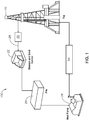
- FIG. 1 is a schematic of a drilling rig 100 with an example auto cleaning system 50 for cleaning a drilling fluid in a drilling operation, according to one or more example embodiments of the disclosure.
- the drilling fluid or drilling mud may circulate from flow line of drilling rig 20 to shakers 22, from shakers 22 to mud pit 24, from mud pit 24 to mud pump 26, and from mud pump 26 back to the stand pipe or rig 20.
- the auto cleaning system 50 can be installed between drilling rig 20 and shakers 22, or between mud pump 26 and drilling rig 20.
- Each of the drilling equipment may be interconnected via a pipe line 28 that may transport the drilling fluid for performing the drilling operation.
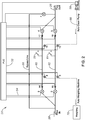
- FIG. 2 illustrates the auto cleaning system 50 in further detail.
- the system 50 may be used for cleaning a drilling fluid in a drilling operation, according to one or more example embodiments of the disclosure.
- System 50 may include two pipe screens located in two independent lines 60, 62 that can be allocated between mud pumps and the rig or rig floor and shakers.
- the system 50 can be electronically monitored using individual pressure monitoring and the mud can pass through one line, while another line may work as a backup.
- the system 50 may be able to collect the metal particles on the mud going in/out of the hole, as well as determine the weight of this material.
- the information can also be delivered to the rig floor via monitor control, for example.
- the auto cleaning system 50 includes a close loop system without exposing the rig crew to any metal particles coming out of the hole.
- the system may be able to collect metal particles in the mud in real time without the need for installing magnets on the shakers during drilling operation.
- the system is designed with two main lines 60, 62 that can be switched from each other according the pressure drop in each screen. As soon as the pressure increases in one line and goes beyond the previous input limits, the system 50 automatically switches to the next line, and the auto clean pump may be activated to clean the line and send the metal particles for weighing on the weighing machine.
- the system 50 can be installed in two different places on the rig system and operated independently, such as between rig pumps and rig floor. It can also be installed in the stand pipe, avoiding that materials coming from tanks from going into the drill pipe, for example, damaging the directional drilling equipment.
- the system 50 can also be installed between the rig floor and shakers.
- It can be installed in the flow line, so that it may work as another barrel to protect the metal particles from going to the mud tanks, and contaminating the mud system with the fine material, or it can be installed while drilling out the casing (open window) to perform a sidetrack.
- the auto cleaning system 50 includes a first line 60 including a first entrance valve 3 configured to allow the drilling fluid to flow into the first line 60, a first exit valve 4, a first pressure sensor 14 configured to measure a first pressure of the drilling fluid in the first line 60 at an entrance point, a second pressure sensor 17 configured to measure a second pressure of the drilling fluid in the first line 60 at an exit point, a first auto clean valve 8 and a second auto clean valve 11 configured to allow the drilling fluid to flow out of the first line 60.
- the system also includes a second line 62 including a second entrance valve 2 configured to allow the drilling fluid to flow into the second line 62, a second exit valve 5, a third pressure sensor 15 configured to measure a third pressure of the drilling fluid in the second line 62 at an entrance point, a fourth pressure sensor 18 configured to measure a fourth pressure of the drilling fluid in the second line 62 at an exit point, a third auto clean valve 9 and a fourth auto clean valve 12 configured to allow the drilling fluid to flow out of the second line 62.
- the system 50 may also include an auto clean pump 58 operatively connected to the first auto clean valve 8, the second auto clean valve 11, the third auto clean valve 9, and the fourth auto clean valve 12 via an auto clean line.
- the auto clean pump 58 may be configured to receive the drilling fluid from the first line 60 or the second line 62 and remove metal particles from the drilling fluid.
- the auto clean pump 58 receives the drilling fluid from these lines backwards so they can flush the debris out of the line.
- the system 50 further includes an electromagnetic device 75 (shown in FIG. 3 ) around at least a portion of the first line 60 and the second line 62.
- the electromagnetic device 75 is energized when the drilling fluid is passing through a line.
- the system 50 also includes a controller 52, such as a PLC, that is operatively connected at least to valves 2-4, 7, pressure sensors 14, 15, 17, 18, auto clean valves 8, 9, 11, 12 via lines 54 for controlling an operation thereof.
- the controller 52 may be configured to determine that the difference between the second pressure and the first pressure is above a predetermined threshold value, and at least partially open the second entrance valve 2 to divert drilling fluid intake from the first line 60 to the second line 62, and close the first entrance valve 3 to stop the drilling fluid from entering the first line 60.
- the controller 52 may further be configured to at least partially open the first auto clean valve 8 and/or auto clean valve 11 to divert the drilling fluid in the first line 60 to the auto clean pump 58 for removal of the metal particles from the drilling fluid.
- the controller 52 may also be further configured to de-energize the electromagnetic device 75 after at least partially opening the first auto clean valve 8 to divert the drilling fluid in the first line 60 to the auto clean pump 58 for removal of the metal particles from the drilling fluid.
- the controller may determine the difference between the third pressure and the fourth pressure is above the predetermined threshold value, and at least partially open the entrance valve 3 to divert drilling fluid intake from the second line 62 to the first line 60, and close the entrance valve 2 to stop the drilling fluid from entering the second line 62.
- a weighing machine 70 may be operatively connected to the first auto clean valve 8 and the second auto clean valve 9 via the auto clean line 68, and the weighing machine may be configured to weigh the metal particles in the drilling fluid. All of the entrance valves used in the example embodiments may include High Closing Ratio or Hydraulic Control Remote (HCR) valves.
- HCR Hydraulic Control Remote
- the electromagnetic screen system 50 is able to collect the material particles in the mud and send it to a weighing machine 70 for weighing, which can then inform drillers about the real weight of metal that has been collected.
- a total amount of metal weight can be updated and displayed on the rig floor via a real time monitoring screen, for example.
- line 60 if line 60 is active, the system automatically keep valves 3 and 4 open, and closes valves 2, 5, 7, 8, 9, 11 and 12 so the flow will pass throughout line 60.
- the electromagnetic system on this line 60 may be activated via switch 56 so that the electromagnetic device 75 (shown in FIG. 3 ) is able to collect the metal particles.
- the system 50 may automatically open valves 2 and 5, and close valves 3, 4, 7, 8, 9, 11 and 12 so the flow may pass throughout line 62.
- the electromagnetic system on this line 62 may be activated at this time in order to be able to collect the metal particles in line 62.
- valves 3, 4, 7, 9, 12 may be automatically closed, and valves 8 and 11 may be open.
- the electromagnetic system may release the metal particles previously collected and now the auto clean pump may be activated, sending the metal particles to be collected in the weighing machine 70.
- valves 2, 5, 7, 8, 11 may be automatically closed, and valves 3, 4, 9 and 12 may be open.
- the electromagnetic system may release the metal particles previously collected and now the auto clean pump 58 may be activated, sending the metal particles to be collected in the weighing machine 70.
- valves 2, 3, 4, 5, 8, 9, 11, and 12 may be automatically closed, and valves 7 may be open so the flow may be direct to the bypass line 66.
- Signals can be sent to a PLC 52 with a monitor or human machine interface (HMI) to analyze and alarm, and also can operate an actuated valve to switch/divert the suction intake to a backup suction until fixing the problem.
- HMI human machine interface
- FIG. 3 illustrates an electromagnetic component 75 of an example auto cleaning system 50 for cleaning a drilling fluid in a drilling operation, according to one or more example embodiments of the disclosure.
- an electromagnetic system or device 75 is installed around lines 60, 62 so as to collect metal particles from the drilling fluid.
- the device 75 may be energized by the controller 52 any time there is fluid flowing in a line.
- the controller 52 may do so by closing the electric switch 64 and completing the circuit.
- the metal particles 74 in the drilling fluid 72 get collected on an inner surface of the line 60, 62.
- the controller 52 de-energizes the device 75 by opening the switch 64, the metal particles are dislodged and sent to the weighing machine 70 for weighing and displaying the weight to operation personnel.
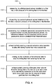
- FIG. 4 illustrates example operations in a method 400 for auto cleaning a drilling fluid in a drilling operation, according to one or more example embodiments of the disclosure.
- the example method disclosed herein is presented and described as a series of blocks (with each block representing an action or an operation in a method, for example).
- the disclosed method is not limited by the order of blocks and associated actions or operations, as some blocks may occur in different orders and/or concurrently with other blocks from those that are shown and described herein.
- the various methods (or processes or techniques) in accordance with this disclosure can be alternatively represented as a series of interrelated states or events, such as in a state diagram.
- the method 400 includes at step 402, measuring, by a first pressure sensor installed on a first line, a first pressure of the drilling fluid at a first point.
- the first point can be, for example, an entrance point on the first line.
- the method further includes at step 404, measuring, by a second pressure sensor installed on the first line, a second pressure of the drilling fluid at a second point.
- the second point can be, for example, and exit point on the first line.
- the first line may include a first entrance valve configured to allow the drilling fluid to flow into the first line, and a first auto clean valve configured to allow the drilling fluid to flow out of the first line.
- the method 400 further includes, at step 406, determining, by a controller operatively connected to the first pressure sensor, the second pressure sensor, the first entrance valve, and the first auto clean valve, that a difference between the second pressure and the first pressure is above a predetermined threshold value.
- the controller at least partially opens a second entrance valve configured to allow the drilling fluid to flow into a second line, and step 410 the controller causes to close the first entrance valve to stop the drilling fluid from entering the first line.
- the method also includes, at step 412, the controller at least partially opening the first auto clean valve to divert the drilling fluid in the first line to an auto clean pump operatively connected to the first auto clean valve via an auto clean line for removal of metal particles from the drilling fluid.
- the method may also include receiving, by the auto clean pump, the drilling fluid from the first line to remove metal particles from the drilling fluid.
- FIG. 5 illustrates example operations in a method 500 for auto cleaning a drilling fluid in a drilling operation, according to one or more example embodiments of the disclosure.
- the method 500 may include at step 502 receiving, by the auto clean pump 58, the drilling fluid from the first line 60 to remove metal particles from the drilling fluid.
- the method may further include determining, by the controller 52 operatively connected to a first exit valve 4 operable to allow the drilling fluid to flow out of the first line 60, and a third pressure sensor 17 for measuring a third pressure of the drilling fluid in the first line 60, the third pressure is above the predetermined threshold value, and closing the first exit valve 4 to stop the drilling fluid from exiting the first line 60.
- the method may also include at least partially opening a third auto clean valve 11 operable to allow the drilling fluid to flow out of the first line 60 into the auto clean pump 58 for removal of metal particles from the drilling fluid.
- the method may further include at step 504 weighing the metal particles in the drilling fluid, by a weighing machine 70 operatively connected to the first auto clean valve 8 via the auto clean line 68.
- the method 500 may also include at step 506 displaying a weight of the metal particles on a human machine interface operatively connected to the controller, and receiving an instruction from an operator.
- the phrase "at least partially opening the valve” refers to the operation of at least partially opening the valve. For example, a valve may be partially open or completely open at a certain point in time. As described herein, the phrase "at least partially open” covers both scenarios where a valve may be partially or fully open.
- the auto cleaning system 50 can also include a human machine interface (not shown) that may be connected to the controller for displaying a message and receiving an instruction from an operator.
- the controller 52 may actuate any of the valves 2-12 based on an input received form the operator.
- conditional language such as, among others, “can,” “could,” “might,” or “may,” unless specifically stated otherwise, or otherwise understood within the context as used, is generally intended to convey that certain implementations could include, while other implementations do not include, certain features, elements, and/or operations. Thus, such conditional language generally is not intended to imply that features, elements, and/or operations are in any way required for one or more implementations or that one or more implementations necessarily include logic for deciding, with or without user input or prompting, whether these features, elements, and/or operations are included or are to be performed in any particular implementation.
Landscapes
- Engineering & Computer Science (AREA)
- Chemical Kinetics & Catalysis (AREA)
- Chemical & Material Sciences (AREA)
- Mining & Mineral Resources (AREA)
- Life Sciences & Earth Sciences (AREA)
- Geology (AREA)
- Physics & Mathematics (AREA)
- General Life Sciences & Earth Sciences (AREA)
- Fluid Mechanics (AREA)
- Geochemistry & Mineralogy (AREA)
- Environmental & Geological Engineering (AREA)
- Mechanical Engineering (AREA)
- General Physics & Mathematics (AREA)
- Automation & Control Theory (AREA)
- Earth Drilling (AREA)
- Cleaning In General (AREA)
Claims (15)
- Automatische Reinigungsanlage (50) zum Reinigen einer Bohrspülung bei einem Bohrvorgang, wobei die automatische Reinigungsanlage Folgendes umfasst:eine erste Leitung (60), die ein erstes Eingangsventil (3), das dafür konfiguriert ist, zu ermöglichen, dass die Bohrspülung in die erste Leitung strömt, einen ersten Drucksensor (14), der dafür konfiguriert ist, einen ersten Druck der Bohrspülung in der ersten Leitung an einem Eintrittspunkt zu messen, einen zweiten Drucksensor (17), der dafür konfiguriert ist, einen zweiten Druck der Bohrspülung in der ersten Leitung an einem Austrittspunkt zu messen, und ein erstes Automatikreinigungsventil (8), das dafür konfiguriert ist, zu ermöglichen, dass die Bohrspülung aus der ersten Leitung ausströmt, umfasst,eine zweite Leitung (62), die ein zweites Eingangsventil (2), das dafür konfiguriert ist, zu ermöglichen, dass die Bohrspülung in die zweite Leitung strömt, und ein zweites Automatikreinigungsventil (11), das dafür konfiguriert ist, zu ermöglichen, dass die Bohrspülung aus der zweiten Leitung ausströmt, umfasst,eine Automatikreinigungspumpe (58), die über eine Automatikreinigungsleitung (68) funktionsfähig mit dem ersten Automatikreinigungsventil und dem zweiten Automatikreinigungsventil verbunden ist, wobei die Automatikreinigungspumpe dafür konfiguriert ist, die Bohrspülung aus der ersten Leitung oder der zweiten Leitung aufzunehmen und Metallteilchen aus der Bohrspülung zu entfernen,eine elektromagnetische Vorrichtung (75) um mindestens einen Abschnitt der ersten Leitung, um so Metallteilchen aus der Bohrspülung zu sammeln, wobei die elektromagnetische Vorrichtung erregt wird, wenn die Bohrspülung durch die erste Leitung hindurchgeht, undeine Steuerung (52), die funktionsfähig mit mindestens dem ersten Eingangsventil, dem ersten Drucksensor, dem zweiten Drucksensor, dem ersten Automatikreinigungsventil, dem zweiten Eingangsventil, dem zweiten Automatikreinigungsventil, der Automatikreinigungspumpe und der elektromagnetischen Vorrichtung verbunden ist, wobei die Steuerung zu Folgendem konfiguriert ist:festzustellen, dass die Differenz zwischen dem zweiten Druck und dem ersten Druck über einem vorbestimmten Schwellenwert liegt,das zweite Eingangsventil mindestens teilweise zu öffnen, um eine Bohrspülungsaufnahme von der ersten Leitung zu der zweiten Leitung umzuleiten, unddas erste Eingangsventil zu schließen, um die Bohrspülung daran zu hindern, in die erste Leitung einzutreten.
- Automatische Reinigungsanlage nach Anspruch 1, wobei die Steuerung ferner dafür konfiguriert ist, das erste Automatikreinigungsventil mindestens teilweise zu öffnen, um die Bohrspülung in der ersten Leitung von der Automatikreinigungspumpe zum Entfernen der Metallteilchen aus der Bohrspülung zu der automatischen Reinigung umzuleiten, wahlweise, wobei die Steuerung ferner dafür konfiguriert ist, die elektromagnetische Vorrichtung auszuschalten nach dem mindestens teilweisen Öffnen des ersten Automatikreinigungsventils, um die Bohrspülung in der ersten Leitung zu der Automatikreinigungspumpe umzuleiten, zum Entfernen der Metallteilchen aus der Bohrspülung.
- Automatische Reinigungsanlage nach einem der vorhergehenden Ansprüche, wobei die zweite Leitung ferner einen dritten Drucksensor (17), der dafür konfiguriert ist, einen dritten Druck der Bohrspülung in der zweiten Leitung an einem Eintrittspunkt zu messen, und einen vierten Drucksensor (18), der dafür konfiguriert ist, einen vierten Druck der Bohrspülung in der zweiten Leitung an einem Austrittspunkt zu messen, umfasst, wobei die Steuerung funktionsfähig mit dem dritten Drucksensor, dem vierten Drucksensor verbunden ist, wobei die Steuerung zu Folgendem konfiguriert ist:festzustellen, dass die Differenz zwischen dem dritten Druck und dem vierten Druck über dem vorbestimmten Schwellenwert liegt,das erste Eingangsventil mindestens teilweise zu öffnen, um eine Bohrspülungsaufnahme von der zweiten Leitung zu der ersten Leitung umzuleiten, unddas zweite Eingangsventil zu schließen, um die Bohrspülung daran zu hindern, in die zweite Leitung einzutreten.
- Automatische Reinigungsanlage nach einem der vorhergehenden Ansprüche, die ferner Folgendes umfasst:
eine Wiegemaschine (70), die über die Automatikreinigungsleitung funktionsfähig mit dem ersten Automatikreinigungsventil und dem zweiten Automatikreinigungsventil verbunden ist, wobei die Wiegemaschine dafür konfiguriert ist, die Metallteilchen in der Bohrspülung zu wiegen. - Automatische Reinigungsanlage nach einem der vorhergehenden Ansprüche, wobei das erste Eingangsventil und das zweite Eingangsventil ein Ventil mit hohem Schließverhältnis oder hydraulischer Fernsteuerung (HCR) umfassen.
- Automatische Reinigungsanlage nach einem der vorhergehenden Ansprüche, die ferner Folgendes umfasst
eine Umgehungsleitung (66), die durch ein zweckbestimmtes Umgehungsventil gesteuert wird, das mit der Steuerung verbunden ist, wobei das zweckbestimmte Umgehungsventil dafür konfiguriert ist, zu ermöglichen, dass die Bohrspülung die Automatikreinigungsanlage umgeht. - Automatische Reinigungsanlage nach einem der vorhergehenden Ansprüche, die ferner Folgendes umfasst
eine Mensch-Maschine-Schnittstelle, die funktionsfähig mit der Steuerung verbunden ist, zum Anzeigen einer Warnmeldung, wenn die Bohrspülung von der ersten Leitung zu der zweiten Leitung umgeschaltet wird, und Empfangen einer Anweisung von einem Bediener. - Automatische Reinigungsanlage nach einem der vorhergehenden Ansprüche, wobei die automatische Reinigungsanlage zwischen einer Schlammpumpe (26) und einem Standrohr der Bohranlage (20) oder zwischen dem Standrohr der Bohranlage und einem Schüttelsieb (22) installiert ist.
- Verfahren zum Reinigen einer Bohrspülung bei einem Bohrvorgang unter Verwendung einer automatischen Reinigungsanlage (50), wobei das Verfahren Folgendes umfasst:Messen, durch einen ersten Drucksensor (14), der an einer ersten Leitung (60) installiert ist, eines ersten Drucks der Bohrspülung an einem ersten Punkt,Messen, durch einen zweiten Drucksensor (17), der an der ersten Leitung installiert ist, eines zweiten Drucks der Bohrspülung an einem zweiten Punkt, wobei die erste Leitung ein erstes Eingangsventil (3), das dafür konfiguriert ist, zu ermöglichen, dass die Bohrspülung in die erste Leitung strömt, und ein erstes Automatikreinigungsventil (8), das dafür konfiguriert ist, zu ermöglichen, dass die Bohrspülung aus der ersten Leitung ausströmt, aufweist,Sammeln von Metallteilchen aus der Bohrspülung durch Erregen einer elektromagnetischen Vorrichtung (75) um mindestens einen Abschnitt der ersten Leitung,Feststellen, durch eine Steuerung (52), die funktionsfähig mit dem ersten Drucksensor, dem zweiten Drucksensor, dem ersten Eingangsventil und dem ersten Automatikreinigungsventil verbunden ist, dass eine Differenz zwischen dem zweiten Druck und dem ersten Druck über einem vorbestimmten Schwellenwert liegt,mindestens teilweises Öffnen eines zweiten Eingangsventils (2), das dafür konfiguriert ist, zu ermöglichen, dass die Bohrspülung in eine zweite Leitung (62) strömt, undSchließen, durch die Steuerung, des ersten Eingangsventils, um die Bohrspülung daran zu hindern, in die erste Leitung einzutreten.
- Verfahren nach Anspruch 9, das ferner Folgendes umfasst:dass die Steuerung das erste Automatikreinigungsventil mindestens teilweise öffnet, um die Bohrspülung in der ersten Leitung zu einer Automatikreinigungspumpe (58) umzuleiten, die über eine Automatikreinigungsleitung (68) mit dem ersten Automatikreinigungsventil verbunden ist, zum Entfernen von Metallteilchen aus der Bohrspülung,wobei es wahlweise ferner Folgendes umfasst:
Aufnehmen, durch die Automatikreinigungspumpe, der Bohrspülung aus der ersten Leitung, um Metallteilchen aus der Bohrspülung zu entfernen. - Verfahren nach Anspruch 9 oder Anspruch 10, das ferner Folgendes umfasst:
dass die Steuerung nach dem mindestens teilweisen Öffnen des ersten Automatikreinigungsventils die elektromagnetische Vorrichtung ausschaltet, um die Bohrspülung in der ersten Leitung zu der Automatikreinigungspumpe umzuleiten zum Entfernen der Metallteilchen aus der Bohrspülung. - Verfahren nach einem der Ansprüche 9 bis 11, das ferner Folgendes umfasst:Bereitstellen eines dritten Drucksensors (17), der dafür konfiguriert ist, einen dritten Druck der Bohrspülung in der zweiten Leitung an einem Eintrittspunkt zu messen,Bereitstellen eines vierten Drucksensors (18), der dafür konfiguriert ist, einen vierten Druck der Bohrspülung in der zweiten Leitung an einem Austrittspunkt zu messen,Verbinden der Steuerung mit dem dritten Drucksensor, dem vierten Drucksensor, wobei die Steuerung zu Folgendem konfiguriert ist:festzustellen, dass die Differenz zwischen dem dritten Druck und dem vierten Druck über dem vorbestimmten Schwellenwert liegt,das erste Eingangsventil mindestens teilweise zu öffnen, um eine Bohrspülungsaufnahme von der zweiten Leitung zu der ersten Leitung umzuleiten, unddas zweite Eingangsventil zu schließen, um die Bohrspülung daran zu hindern, in die zweite Leitung einzutreten.
- Verfahren nach einem der Ansprüche 9 bis 12, das ferner Folgendes umfasst:Wiegen der Metallteilchen in der Bohrspülung, durch eine Wiegemaschine (70), die über die Automatikreinigungsleitung funktionsfähig mit dem ersten Automatikreinigungsventil verbunden ist,wobei es wahlweise ferner Folgendes umfasst:
Anzeigen eines Gewichts der Metallteilchen auf einer Mensch-Maschine-Schnittstelle, die funktionsfähig mit der Steuerung verbunden ist, und Empfangen einer Anweisung von einem Bediener. - Verfahren nach einem der Ansprüche 9 bis 13, wobei das erste Eingangsventil und das zweite Eingangsventil ein Ventil mit hohem Schließverhältnis oder hydraulischer Fernsteuerung (HCR) umfassen.
- Verfahren nach einem der Ansprüche 9 bis 14, das ferner Folgendes umfasst:(a) Umgehen der automatischen Reinigungsanlage über eine Umgehungsleitung (66), die durch ein drittes Ventil gesteuert wird, das mit der Steuerung verbunden ist, und/oder(b) Installieren der automatischen Reinigungsanlage zwischen einer Schlammpumpe (26) und einem Standrohr der Bohranlage (20) oder zwischen dem Standrohr der Bohranlage und einem Schüttelsieb (22).
Applications Claiming Priority (2)
| Application Number | Priority Date | Filing Date | Title |
|---|---|---|---|
| US15/788,278 US10603607B2 (en) | 2017-10-19 | 2017-10-19 | Method and apparatus for smart electromagnetic screen system for use in drilling operations |
| PCT/US2018/056617 WO2019079667A1 (en) | 2017-10-19 | 2018-10-19 | METHOD AND APPARATUS FOR INTELLIGENT ELECTROMAGNETIC SCREEN SYSTEM FOR USE IN DRILLING OPERATIONS |
Publications (2)
| Publication Number | Publication Date |
|---|---|
| EP3698008A1 EP3698008A1 (de) | 2020-08-26 |
| EP3698008B1 true EP3698008B1 (de) | 2021-11-17 |
Family
ID=64267927
Family Applications (1)
| Application Number | Title | Priority Date | Filing Date |
|---|---|---|---|
| EP18800393.3A Not-in-force EP3698008B1 (de) | 2017-10-19 | 2018-10-19 | Verfahren und vorrichtung für ein intelligentes elektromagnetisches siebsystem zur verwendung in bohrvorgängen |
Country Status (5)
| Country | Link |
|---|---|
| US (1) | US10603607B2 (de) |
| EP (1) | EP3698008B1 (de) |
| CN (1) | CN111226020B (de) |
| SA (1) | SA520411680B1 (de) |
| WO (1) | WO2019079667A1 (de) |
Families Citing this family (4)
| Publication number | Priority date | Publication date | Assignee | Title |
|---|---|---|---|---|
| US11213768B2 (en) * | 2020-03-30 | 2022-01-04 | Batfer Investment S.A. | Automated sand separator discharge system |
| US11465076B2 (en) | 2020-03-30 | 2022-10-11 | Batfer Investment S.A. | Automated sand separator discharge system |
| US11656203B2 (en) | 2020-12-10 | 2023-05-23 | Batfer Investment S.A. | Apparatus and method for determining solids level in a sand separator |
| US11351481B1 (en) * | 2021-06-29 | 2022-06-07 | North American Automation, LLC | Sand discharge control system |
Family Cites Families (24)
| Publication number | Priority date | Publication date | Assignee | Title |
|---|---|---|---|---|
| US5362962A (en) | 1993-04-16 | 1994-11-08 | Edison Welding Institute | Method and apparatus for measuring pipeline corrosion |
| US5741416A (en) | 1996-10-15 | 1998-04-21 | Tempest Environmental Systems, Inc. | Water purification system having plural pairs of filters and an ozone contact chamber |
| US6609573B1 (en) | 1999-11-24 | 2003-08-26 | Friede & Goldman, Ltd. | Method and apparatus for a horizontal pipe handling system on a self-elevating jack-up drilling unit |
| AU2002323445A1 (en) | 2001-08-29 | 2003-03-18 | Sensor Highway Limited | Method and apparatus for determining the temperature of subterranean wells using fiber optic cable |
| ATE442510T1 (de) | 2003-03-13 | 2009-09-15 | Tesco Corp | Verfahren und vorrichtung zum bohren eines bohrlochs mit einem bohrloch-liner |
| US7096961B2 (en) | 2003-04-29 | 2006-08-29 | Schlumberger Technology Corporation | Method and apparatus for performing diagnostics in a wellbore operation |
| US20050006150A1 (en) | 2003-07-07 | 2005-01-13 | Power Chokes, L.P. | Solids strainer system for a hydraulic choke |
| US7111682B2 (en) | 2003-07-21 | 2006-09-26 | Mark Kevin Blaisdell | Method and apparatus for gas displacement well systems |
| US20070085645A1 (en) * | 2004-08-31 | 2007-04-19 | Ruttley David J | Magnetic tool for retrieving metal objects from a well bore |
| GB0509715D0 (en) * | 2005-05-12 | 2005-06-22 | Specialised Petroleum Serv Ltd | Wellbore cleaning tool and method |
| US7731037B2 (en) | 2007-12-12 | 2010-06-08 | Occidental Oil And Gas Holding Corporation | Separating sand from fluids produced by a well |
| US8127867B1 (en) | 2008-09-30 | 2012-03-06 | Bronco Oilfield Services, Inc. | Method and system for surface filtering of solids from return fluids in well operations |
| US8753517B2 (en) | 2009-05-29 | 2014-06-17 | Petroleum Specialty Rental, Llc | Method and apparatus for removing metallic matter from an oil well circulating completion fluid stream |
| US8409442B2 (en) | 2009-08-20 | 2013-04-02 | Ng Innovations, Inc. | Water separation method and apparatus |
| EA024854B1 (ru) * | 2009-09-10 | 2016-10-31 | Бп Корпорейшн Норт Америка Инк. | Способ и система бурения морских скважин |
| US20110198080A1 (en) | 2010-02-18 | 2011-08-18 | Karl Demong | Debris removal system and method for pressure controlled wellbore drilling and intervention operations |
| US8528665B2 (en) | 2010-10-01 | 2013-09-10 | M-I L.L.C. | Drilling waste management system |
| CN103244064A (zh) * | 2013-04-27 | 2013-08-14 | 上海市离心机械研究所有限公司 | 一种可移动式石油钻井液的离心分离系统 |
| US9194216B2 (en) | 2013-04-29 | 2015-11-24 | Halliburton Energy Services, Inc. | Manipulatable filter system |
| CN105378474A (zh) * | 2013-07-16 | 2016-03-02 | 国际壳牌研究有限公司 | 滤失传感器和方法 |
| US9744485B2 (en) | 2013-08-16 | 2017-08-29 | Pecofacet (Us), Inc. | Fluid treatment system |
| US20160097247A1 (en) | 2014-10-01 | 2016-04-07 | H2O Oilfield Services | Methods of filtering a fluid using a portable fluid filtration apparatus |
| CN105696959B (zh) * | 2016-01-20 | 2018-01-30 | 长江大学 | 智能油气井反循环钻井系统 |
| CN105921402B (zh) * | 2016-06-15 | 2018-11-13 | 成都知融智创知识产权运营有限公司 | 基于二次分离装置的钻井液净化设备 |
-
2017
- 2017-10-19 US US15/788,278 patent/US10603607B2/en active Active
-
2018
- 2018-10-19 EP EP18800393.3A patent/EP3698008B1/de not_active Not-in-force
- 2018-10-19 WO PCT/US2018/056617 patent/WO2019079667A1/en not_active Ceased
- 2018-10-19 CN CN201880067117.8A patent/CN111226020B/zh not_active Expired - Fee Related
-
2020
- 2020-04-01 SA SA520411680A patent/SA520411680B1/ar unknown
Also Published As
| Publication number | Publication date |
|---|---|
| SA520411680B1 (ar) | 2022-11-01 |
| EP3698008A1 (de) | 2020-08-26 |
| US20190118118A1 (en) | 2019-04-25 |
| US10603607B2 (en) | 2020-03-31 |
| CN111226020A (zh) | 2020-06-02 |
| WO2019079667A1 (en) | 2019-04-25 |
| CN111226020B (zh) | 2022-04-19 |
Similar Documents
| Publication | Publication Date | Title |
|---|---|---|
| US10603607B2 (en) | Method and apparatus for smart electromagnetic screen system for use in drilling operations | |
| US10677032B1 (en) | Electric submersible pump intake system, apparatus, and method | |
| US11607628B2 (en) | Systems and processes for automated sand separation | |
| US20110198080A1 (en) | Debris removal system and method for pressure controlled wellbore drilling and intervention operations | |
| US11220905B2 (en) | Method and apparatus for controlling downhole water production | |
| US20250277416A1 (en) | Method and apparatus for automatic drill out | |
| EP3698009B1 (de) | Systeme und verfahren mit rohrsieb zur intelligenten automatischen reinigung für bohrarbeiten | |
| NO20220703A1 (en) | Completion systems and methods to perform completion operations | |
| EP3488072B1 (de) | Anordnung einer unbemannten und ferngesteuerten produktionsanlage | |
| CN104514503A (zh) | 岩屑过滤装置 | |
| CN111247307B (zh) | 包括用于钻井操作的智能样品捕集器的系统及方法 | |
| AU2020425745B2 (en) | Completion systems and methods to perform completion operations | |
| CA3120997C (en) | Rotatable magnet cradle for swarf separation | |
| US12576349B2 (en) | Automated control of high-pressure filter systems | |
| CA3076882C (en) | Method and apparatus for controlling downhole water production | |
| CN115628195A (zh) | 一种智能海水提升泵控制方法 |
Legal Events
| Date | Code | Title | Description |
|---|---|---|---|
| STAA | Information on the status of an ep patent application or granted ep patent |
Free format text: STATUS: UNKNOWN |
|
| STAA | Information on the status of an ep patent application or granted ep patent |
Free format text: STATUS: THE INTERNATIONAL PUBLICATION HAS BEEN MADE |
|
| PUAI | Public reference made under article 153(3) epc to a published international application that has entered the european phase |
Free format text: ORIGINAL CODE: 0009012 |
|
| STAA | Information on the status of an ep patent application or granted ep patent |
Free format text: STATUS: REQUEST FOR EXAMINATION WAS MADE |
|
| 17P | Request for examination filed |
Effective date: 20200512 |
|
| AK | Designated contracting states |
Kind code of ref document: A1 Designated state(s): AL AT BE BG CH CY CZ DE DK EE ES FI FR GB GR HR HU IE IS IT LI LT LU LV MC MK MT NL NO PL PT RO RS SE SI SK SM TR |
|
| AX | Request for extension of the european patent |
Extension state: BA ME |
|
| DAV | Request for validation of the european patent (deleted) | ||
| DAX | Request for extension of the european patent (deleted) | ||
| GRAP | Despatch of communication of intention to grant a patent |
Free format text: ORIGINAL CODE: EPIDOSNIGR1 |
|
| STAA | Information on the status of an ep patent application or granted ep patent |
Free format text: STATUS: GRANT OF PATENT IS INTENDED |
|
| INTG | Intention to grant announced |
Effective date: 20210528 |
|
| GRAS | Grant fee paid |
Free format text: ORIGINAL CODE: EPIDOSNIGR3 |
|
| GRAA | (expected) grant |
Free format text: ORIGINAL CODE: 0009210 |
|
| STAA | Information on the status of an ep patent application or granted ep patent |
Free format text: STATUS: THE PATENT HAS BEEN GRANTED |
|
| AK | Designated contracting states |
Kind code of ref document: B1 Designated state(s): AL AT BE BG CH CY CZ DE DK EE ES FI FR GB GR HR HU IE IS IT LI LT LU LV MC MK MT NL NO PL PT RO RS SE SI SK SM TR |
|
| REG | Reference to a national code |
Ref country code: GB Ref legal event code: FG4D |
|
| REG | Reference to a national code |
Ref country code: IE Ref legal event code: FG4D |
|
| REG | Reference to a national code |
Ref country code: DE Ref legal event code: R096 Ref document number: 602018026925 Country of ref document: DE |
|
| REG | Reference to a national code |
Ref country code: AT Ref legal event code: REF Ref document number: 1448200 Country of ref document: AT Kind code of ref document: T Effective date: 20211215 |
|
| REG | Reference to a national code |
Ref country code: LT Ref legal event code: MG9D |
|
| REG | Reference to a national code |
Ref country code: NL Ref legal event code: MP Effective date: 20211117 |
|
| REG | Reference to a national code |
Ref country code: AT Ref legal event code: MK05 Ref document number: 1448200 Country of ref document: AT Kind code of ref document: T Effective date: 20211117 |
|
| PG25 | Lapsed in a contracting state [announced via postgrant information from national office to epo] |
Ref country code: RS Free format text: LAPSE BECAUSE OF FAILURE TO SUBMIT A TRANSLATION OF THE DESCRIPTION OR TO PAY THE FEE WITHIN THE PRESCRIBED TIME-LIMIT Effective date: 20211117 Ref country code: LT Free format text: LAPSE BECAUSE OF FAILURE TO SUBMIT A TRANSLATION OF THE DESCRIPTION OR TO PAY THE FEE WITHIN THE PRESCRIBED TIME-LIMIT Effective date: 20211117 Ref country code: FI Free format text: LAPSE BECAUSE OF FAILURE TO SUBMIT A TRANSLATION OF THE DESCRIPTION OR TO PAY THE FEE WITHIN THE PRESCRIBED TIME-LIMIT Effective date: 20211117 Ref country code: BG Free format text: LAPSE BECAUSE OF FAILURE TO SUBMIT A TRANSLATION OF THE DESCRIPTION OR TO PAY THE FEE WITHIN THE PRESCRIBED TIME-LIMIT Effective date: 20220217 Ref country code: AT Free format text: LAPSE BECAUSE OF FAILURE TO SUBMIT A TRANSLATION OF THE DESCRIPTION OR TO PAY THE FEE WITHIN THE PRESCRIBED TIME-LIMIT Effective date: 20211117 |
|
| PG25 | Lapsed in a contracting state [announced via postgrant information from national office to epo] |
Ref country code: IS Free format text: LAPSE BECAUSE OF FAILURE TO SUBMIT A TRANSLATION OF THE DESCRIPTION OR TO PAY THE FEE WITHIN THE PRESCRIBED TIME-LIMIT Effective date: 20220317 Ref country code: SE Free format text: LAPSE BECAUSE OF FAILURE TO SUBMIT A TRANSLATION OF THE DESCRIPTION OR TO PAY THE FEE WITHIN THE PRESCRIBED TIME-LIMIT Effective date: 20211117 Ref country code: PT Free format text: LAPSE BECAUSE OF FAILURE TO SUBMIT A TRANSLATION OF THE DESCRIPTION OR TO PAY THE FEE WITHIN THE PRESCRIBED TIME-LIMIT Effective date: 20220317 Ref country code: PL Free format text: LAPSE BECAUSE OF FAILURE TO SUBMIT A TRANSLATION OF THE DESCRIPTION OR TO PAY THE FEE WITHIN THE PRESCRIBED TIME-LIMIT Effective date: 20211117 Ref country code: NO Free format text: LAPSE BECAUSE OF FAILURE TO SUBMIT A TRANSLATION OF THE DESCRIPTION OR TO PAY THE FEE WITHIN THE PRESCRIBED TIME-LIMIT Effective date: 20220217 Ref country code: NL Free format text: LAPSE BECAUSE OF FAILURE TO SUBMIT A TRANSLATION OF THE DESCRIPTION OR TO PAY THE FEE WITHIN THE PRESCRIBED TIME-LIMIT Effective date: 20211117 Ref country code: LV Free format text: LAPSE BECAUSE OF FAILURE TO SUBMIT A TRANSLATION OF THE DESCRIPTION OR TO PAY THE FEE WITHIN THE PRESCRIBED TIME-LIMIT Effective date: 20211117 Ref country code: HR Free format text: LAPSE BECAUSE OF FAILURE TO SUBMIT A TRANSLATION OF THE DESCRIPTION OR TO PAY THE FEE WITHIN THE PRESCRIBED TIME-LIMIT Effective date: 20211117 Ref country code: GR Free format text: LAPSE BECAUSE OF FAILURE TO SUBMIT A TRANSLATION OF THE DESCRIPTION OR TO PAY THE FEE WITHIN THE PRESCRIBED TIME-LIMIT Effective date: 20220218 |
|
| PG25 | Lapsed in a contracting state [announced via postgrant information from national office to epo] |
Ref country code: SM Free format text: LAPSE BECAUSE OF FAILURE TO SUBMIT A TRANSLATION OF THE DESCRIPTION OR TO PAY THE FEE WITHIN THE PRESCRIBED TIME-LIMIT Effective date: 20211117 Ref country code: SK Free format text: LAPSE BECAUSE OF FAILURE TO SUBMIT A TRANSLATION OF THE DESCRIPTION OR TO PAY THE FEE WITHIN THE PRESCRIBED TIME-LIMIT Effective date: 20211117 Ref country code: RO Free format text: LAPSE BECAUSE OF FAILURE TO SUBMIT A TRANSLATION OF THE DESCRIPTION OR TO PAY THE FEE WITHIN THE PRESCRIBED TIME-LIMIT Effective date: 20211117 Ref country code: ES Free format text: LAPSE BECAUSE OF FAILURE TO SUBMIT A TRANSLATION OF THE DESCRIPTION OR TO PAY THE FEE WITHIN THE PRESCRIBED TIME-LIMIT Effective date: 20211117 Ref country code: EE Free format text: LAPSE BECAUSE OF FAILURE TO SUBMIT A TRANSLATION OF THE DESCRIPTION OR TO PAY THE FEE WITHIN THE PRESCRIBED TIME-LIMIT Effective date: 20211117 Ref country code: DK Free format text: LAPSE BECAUSE OF FAILURE TO SUBMIT A TRANSLATION OF THE DESCRIPTION OR TO PAY THE FEE WITHIN THE PRESCRIBED TIME-LIMIT Effective date: 20211117 Ref country code: CZ Free format text: LAPSE BECAUSE OF FAILURE TO SUBMIT A TRANSLATION OF THE DESCRIPTION OR TO PAY THE FEE WITHIN THE PRESCRIBED TIME-LIMIT Effective date: 20211117 |
|
| REG | Reference to a national code |
Ref country code: DE Ref legal event code: R097 Ref document number: 602018026925 Country of ref document: DE |
|
| PLBE | No opposition filed within time limit |
Free format text: ORIGINAL CODE: 0009261 |
|
| STAA | Information on the status of an ep patent application or granted ep patent |
Free format text: STATUS: NO OPPOSITION FILED WITHIN TIME LIMIT |
|
| 26N | No opposition filed |
Effective date: 20220818 |
|
| PG25 | Lapsed in a contracting state [announced via postgrant information from national office to epo] |
Ref country code: AL Free format text: LAPSE BECAUSE OF FAILURE TO SUBMIT A TRANSLATION OF THE DESCRIPTION OR TO PAY THE FEE WITHIN THE PRESCRIBED TIME-LIMIT Effective date: 20211117 |
|
| PGFP | Annual fee paid to national office [announced via postgrant information from national office to epo] |
Ref country code: GB Payment date: 20220908 Year of fee payment: 5 |
|
| PG25 | Lapsed in a contracting state [announced via postgrant information from national office to epo] |
Ref country code: SI Free format text: LAPSE BECAUSE OF FAILURE TO SUBMIT A TRANSLATION OF THE DESCRIPTION OR TO PAY THE FEE WITHIN THE PRESCRIBED TIME-LIMIT Effective date: 20211117 |
|
| REG | Reference to a national code |
Ref country code: DE Ref legal event code: R119 Ref document number: 602018026925 Country of ref document: DE |
|
| PG25 | Lapsed in a contracting state [announced via postgrant information from national office to epo] |
Ref country code: MC Free format text: LAPSE BECAUSE OF FAILURE TO SUBMIT A TRANSLATION OF THE DESCRIPTION OR TO PAY THE FEE WITHIN THE PRESCRIBED TIME-LIMIT Effective date: 20211117 Ref country code: IT Free format text: LAPSE BECAUSE OF FAILURE TO SUBMIT A TRANSLATION OF THE DESCRIPTION OR TO PAY THE FEE WITHIN THE PRESCRIBED TIME-LIMIT Effective date: 20211117 |
|
| REG | Reference to a national code |
Ref country code: CH Ref legal event code: PL |
|
| REG | Reference to a national code |
Ref country code: BE Ref legal event code: MM Effective date: 20221031 |
|
| PG25 | Lapsed in a contracting state [announced via postgrant information from national office to epo] |
Ref country code: LU Free format text: LAPSE BECAUSE OF NON-PAYMENT OF DUE FEES Effective date: 20221019 |
|
| P01 | Opt-out of the competence of the unified patent court (upc) registered |
Effective date: 20230526 |
|
| PG25 | Lapsed in a contracting state [announced via postgrant information from national office to epo] |
Ref country code: LI Free format text: LAPSE BECAUSE OF NON-PAYMENT OF DUE FEES Effective date: 20221031 Ref country code: FR Free format text: LAPSE BECAUSE OF NON-PAYMENT OF DUE FEES Effective date: 20221031 Ref country code: DE Free format text: LAPSE BECAUSE OF NON-PAYMENT OF DUE FEES Effective date: 20230503 Ref country code: CH Free format text: LAPSE BECAUSE OF NON-PAYMENT OF DUE FEES Effective date: 20221031 |
|
| PG25 | Lapsed in a contracting state [announced via postgrant information from national office to epo] |
Ref country code: BE Free format text: LAPSE BECAUSE OF NON-PAYMENT OF DUE FEES Effective date: 20221031 |
|
| PG25 | Lapsed in a contracting state [announced via postgrant information from national office to epo] |
Ref country code: IE Free format text: LAPSE BECAUSE OF NON-PAYMENT OF DUE FEES Effective date: 20221019 |
|
| PG25 | Lapsed in a contracting state [announced via postgrant information from national office to epo] |
Ref country code: CY Free format text: LAPSE BECAUSE OF FAILURE TO SUBMIT A TRANSLATION OF THE DESCRIPTION OR TO PAY THE FEE WITHIN THE PRESCRIBED TIME-LIMIT Effective date: 20211117 |
|
| PG25 | Lapsed in a contracting state [announced via postgrant information from national office to epo] |
Ref country code: MK Free format text: LAPSE BECAUSE OF FAILURE TO SUBMIT A TRANSLATION OF THE DESCRIPTION OR TO PAY THE FEE WITHIN THE PRESCRIBED TIME-LIMIT Effective date: 20211117 Ref country code: HU Free format text: LAPSE BECAUSE OF FAILURE TO SUBMIT A TRANSLATION OF THE DESCRIPTION OR TO PAY THE FEE WITHIN THE PRESCRIBED TIME-LIMIT; INVALID AB INITIO Effective date: 20181019 |
|
| GBPC | Gb: european patent ceased through non-payment of renewal fee |
Effective date: 20231019 |
|
| PG25 | Lapsed in a contracting state [announced via postgrant information from national office to epo] |
Ref country code: TR Free format text: LAPSE BECAUSE OF FAILURE TO SUBMIT A TRANSLATION OF THE DESCRIPTION OR TO PAY THE FEE WITHIN THE PRESCRIBED TIME-LIMIT Effective date: 20211117 |
|
| PG25 | Lapsed in a contracting state [announced via postgrant information from national office to epo] |
Ref country code: GB Free format text: LAPSE BECAUSE OF NON-PAYMENT OF DUE FEES Effective date: 20231019 |
|
| PG25 | Lapsed in a contracting state [announced via postgrant information from national office to epo] |
Ref country code: GB Free format text: LAPSE BECAUSE OF NON-PAYMENT OF DUE FEES Effective date: 20231019 |
|
| PG25 | Lapsed in a contracting state [announced via postgrant information from national office to epo] |
Ref country code: MT Free format text: LAPSE BECAUSE OF FAILURE TO SUBMIT A TRANSLATION OF THE DESCRIPTION OR TO PAY THE FEE WITHIN THE PRESCRIBED TIME-LIMIT Effective date: 20211117 |