EP3697601B1 - Herstellung eines verbundstoffes - Google Patents
Herstellung eines verbundstoffes Download PDFInfo
- Publication number
- EP3697601B1 EP3697601B1 EP18795776.6A EP18795776A EP3697601B1 EP 3697601 B1 EP3697601 B1 EP 3697601B1 EP 18795776 A EP18795776 A EP 18795776A EP 3697601 B1 EP3697601 B1 EP 3697601B1
- Authority
- EP
- European Patent Office
- Prior art keywords
- lay
- stations
- pieces
- forming
- cutting
- Prior art date
- Legal status (The legal status is an assumption and is not a legal conclusion. Google has not performed a legal analysis and makes no representation as to the accuracy of the status listed.)
- Active
Links
Images
Classifications
-
- B—PERFORMING OPERATIONS; TRANSPORTING
- B29—WORKING OF PLASTICS; WORKING OF SUBSTANCES IN A PLASTIC STATE IN GENERAL
- B29C—SHAPING OR JOINING OF PLASTICS; SHAPING OF MATERIAL IN A PLASTIC STATE, NOT OTHERWISE PROVIDED FOR; AFTER-TREATMENT OF THE SHAPED PRODUCTS, e.g. REPAIRING
- B29C70/00—Shaping composites, i.e. plastics material comprising reinforcements, fillers or preformed parts, e.g. inserts
- B29C70/04—Shaping composites, i.e. plastics material comprising reinforcements, fillers or preformed parts, e.g. inserts comprising reinforcements only, e.g. self-reinforcing plastics
- B29C70/28—Shaping operations therefor
- B29C70/30—Shaping by lay-up, i.e. applying fibres, tape or broadsheet on a mould, former or core; Shaping by spray-up, i.e. spraying of fibres on a mould, former or core
- B29C70/38—Automated lay-up, e.g. using robots, laying filaments according to predetermined patterns
-
- B—PERFORMING OPERATIONS; TRANSPORTING
- B29—WORKING OF PLASTICS; WORKING OF SUBSTANCES IN A PLASTIC STATE IN GENERAL
- B29B—PREPARATION OR PRETREATMENT OF THE MATERIAL TO BE SHAPED; MAKING GRANULES OR PREFORMS; RECOVERY OF PLASTICS OR OTHER CONSTITUENTS OF WASTE MATERIAL CONTAINING PLASTICS
- B29B11/00—Making preforms
- B29B11/14—Making preforms characterised by structure or composition
- B29B11/16—Making preforms characterised by structure or composition comprising fillers or reinforcement
-
- B—PERFORMING OPERATIONS; TRANSPORTING
- B29—WORKING OF PLASTICS; WORKING OF SUBSTANCES IN A PLASTIC STATE IN GENERAL
- B29C—SHAPING OR JOINING OF PLASTICS; SHAPING OF MATERIAL IN A PLASTIC STATE, NOT OTHERWISE PROVIDED FOR; AFTER-TREATMENT OF THE SHAPED PRODUCTS, e.g. REPAIRING
- B29C31/00—Handling, e.g. feeding of the material to be shaped, storage of plastics material before moulding; Automation, i.e. automated handling lines in plastics processing plants, e.g. using manipulators or robots
- B29C31/04—Feeding of the material to be moulded, e.g. into a mould cavity
- B29C31/08—Feeding of the material to be moulded, e.g. into a mould cavity of preforms to be moulded, e.g. tablets, fibre reinforced preforms, extruded ribbons, tubes or profiles; Manipulating means specially adapted for feeding preforms, e.g. supports conveyors
- B29C31/085—Feeding of the material to be moulded, e.g. into a mould cavity of preforms to be moulded, e.g. tablets, fibre reinforced preforms, extruded ribbons, tubes or profiles; Manipulating means specially adapted for feeding preforms, e.g. supports conveyors combined with positioning the preforms according to predetermined patterns, e.g. positioning extruded preforms on conveyors
-
- B—PERFORMING OPERATIONS; TRANSPORTING
- B29—WORKING OF PLASTICS; WORKING OF SUBSTANCES IN A PLASTIC STATE IN GENERAL
- B29C—SHAPING OR JOINING OF PLASTICS; SHAPING OF MATERIAL IN A PLASTIC STATE, NOT OTHERWISE PROVIDED FOR; AFTER-TREATMENT OF THE SHAPED PRODUCTS, e.g. REPAIRING
- B29C70/00—Shaping composites, i.e. plastics material comprising reinforcements, fillers or preformed parts, e.g. inserts
- B29C70/04—Shaping composites, i.e. plastics material comprising reinforcements, fillers or preformed parts, e.g. inserts comprising reinforcements only, e.g. self-reinforcing plastics
- B29C70/06—Fibrous reinforcements only
- B29C70/08—Fibrous reinforcements only comprising combinations of different forms of fibrous reinforcements incorporated in matrix material, forming one or more layers, and with or without non-reinforced layers
-
- B—PERFORMING OPERATIONS; TRANSPORTING
- B29—WORKING OF PLASTICS; WORKING OF SUBSTANCES IN A PLASTIC STATE IN GENERAL
- B29C—SHAPING OR JOINING OF PLASTICS; SHAPING OF MATERIAL IN A PLASTIC STATE, NOT OTHERWISE PROVIDED FOR; AFTER-TREATMENT OF THE SHAPED PRODUCTS, e.g. REPAIRING
- B29C70/00—Shaping composites, i.e. plastics material comprising reinforcements, fillers or preformed parts, e.g. inserts
- B29C70/04—Shaping composites, i.e. plastics material comprising reinforcements, fillers or preformed parts, e.g. inserts comprising reinforcements only, e.g. self-reinforcing plastics
- B29C70/06—Fibrous reinforcements only
- B29C70/10—Fibrous reinforcements only characterised by the structure of fibrous reinforcements, e.g. hollow fibres
- B29C70/12—Fibrous reinforcements only characterised by the structure of fibrous reinforcements, e.g. hollow fibres using fibres of short length, e.g. in the form of a mat
-
- B—PERFORMING OPERATIONS; TRANSPORTING
- B29—WORKING OF PLASTICS; WORKING OF SUBSTANCES IN A PLASTIC STATE IN GENERAL
- B29C—SHAPING OR JOINING OF PLASTICS; SHAPING OF MATERIAL IN A PLASTIC STATE, NOT OTHERWISE PROVIDED FOR; AFTER-TREATMENT OF THE SHAPED PRODUCTS, e.g. REPAIRING
- B29C70/00—Shaping composites, i.e. plastics material comprising reinforcements, fillers or preformed parts, e.g. inserts
- B29C70/04—Shaping composites, i.e. plastics material comprising reinforcements, fillers or preformed parts, e.g. inserts comprising reinforcements only, e.g. self-reinforcing plastics
- B29C70/28—Shaping operations therefor
- B29C70/30—Shaping by lay-up, i.e. applying fibres, tape or broadsheet on a mould, former or core; Shaping by spray-up, i.e. spraying of fibres on a mould, former or core
- B29C70/38—Automated lay-up, e.g. using robots, laying filaments according to predetermined patterns
- B29C70/382—Automated fiber placement [AFP]
-
- B—PERFORMING OPERATIONS; TRANSPORTING
- B29—WORKING OF PLASTICS; WORKING OF SUBSTANCES IN A PLASTIC STATE IN GENERAL
- B29C—SHAPING OR JOINING OF PLASTICS; SHAPING OF MATERIAL IN A PLASTIC STATE, NOT OTHERWISE PROVIDED FOR; AFTER-TREATMENT OF THE SHAPED PRODUCTS, e.g. REPAIRING
- B29C2793/00—Shaping techniques involving a cutting or machining operation
- B29C2793/0027—Cutting off
-
- B—PERFORMING OPERATIONS; TRANSPORTING
- B29—WORKING OF PLASTICS; WORKING OF SUBSTANCES IN A PLASTIC STATE IN GENERAL
- B29C—SHAPING OR JOINING OF PLASTICS; SHAPING OF MATERIAL IN A PLASTIC STATE, NOT OTHERWISE PROVIDED FOR; AFTER-TREATMENT OF THE SHAPED PRODUCTS, e.g. REPAIRING
- B29C70/00—Shaping composites, i.e. plastics material comprising reinforcements, fillers or preformed parts, e.g. inserts
- B29C70/04—Shaping composites, i.e. plastics material comprising reinforcements, fillers or preformed parts, e.g. inserts comprising reinforcements only, e.g. self-reinforcing plastics
- B29C70/06—Fibrous reinforcements only
- B29C70/10—Fibrous reinforcements only characterised by the structure of fibrous reinforcements, e.g. hollow fibres
- B29C70/16—Fibrous reinforcements only characterised by the structure of fibrous reinforcements, e.g. hollow fibres using fibres of substantial or continuous length
- B29C70/18—Fibrous reinforcements only characterised by the structure of fibrous reinforcements, e.g. hollow fibres using fibres of substantial or continuous length in the form of a mat, e.g. sheet moulding compound [SMC]
-
- B—PERFORMING OPERATIONS; TRANSPORTING
- B29—WORKING OF PLASTICS; WORKING OF SUBSTANCES IN A PLASTIC STATE IN GENERAL
- B29C—SHAPING OR JOINING OF PLASTICS; SHAPING OF MATERIAL IN A PLASTIC STATE, NOT OTHERWISE PROVIDED FOR; AFTER-TREATMENT OF THE SHAPED PRODUCTS, e.g. REPAIRING
- B29C70/00—Shaping composites, i.e. plastics material comprising reinforcements, fillers or preformed parts, e.g. inserts
- B29C70/04—Shaping composites, i.e. plastics material comprising reinforcements, fillers or preformed parts, e.g. inserts comprising reinforcements only, e.g. self-reinforcing plastics
- B29C70/28—Shaping operations therefor
- B29C70/54—Component parts, details or accessories; Auxiliary operations, e.g. feeding or storage of prepregs or SMC after impregnation or during ageing
-
- B—PERFORMING OPERATIONS; TRANSPORTING
- B29—WORKING OF PLASTICS; WORKING OF SUBSTANCES IN A PLASTIC STATE IN GENERAL
- B29L—INDEXING SCHEME ASSOCIATED WITH SUBCLASS B29C, RELATING TO PARTICULAR ARTICLES
- B29L2031/00—Other particular articles
- B29L2031/30—Vehicles, e.g. ships or aircraft, or body parts thereof
- B29L2031/3076—Aircrafts
-
- Y—GENERAL TAGGING OF NEW TECHNOLOGICAL DEVELOPMENTS; GENERAL TAGGING OF CROSS-SECTIONAL TECHNOLOGIES SPANNING OVER SEVERAL SECTIONS OF THE IPC; TECHNICAL SUBJECTS COVERED BY FORMER USPC CROSS-REFERENCE ART COLLECTIONS [XRACs] AND DIGESTS
- Y02—TECHNOLOGIES OR APPLICATIONS FOR MITIGATION OR ADAPTATION AGAINST CLIMATE CHANGE
- Y02P—CLIMATE CHANGE MITIGATION TECHNOLOGIES IN THE PRODUCTION OR PROCESSING OF GOODS
- Y02P70/00—Climate change mitigation technologies in the production process for final industrial or consumer products
- Y02P70/50—Manufacturing or production processes characterised by the final manufactured product
Definitions
- This invention relates to manufacturing products from composite materials.
- One class of composite materials involves a matrix in which fibres are embedded.
- the fibres may be in the form of mats, long single lengths or tows, or short fragments.
- a common method of construction is to lay up multiple overlapping layers of fibre mats.
- the mats are then fixed by setting them in the matrix material.
- the shapes and orientations of the mats are chosen so that they will impart the desired strength properties to the resulting component. In a region of the component where stresses are expected to be concentrated there may be more thicknesses of material than at lower stress locations.
- the fibres of the mats may be oriented along the directions of expected tensile stress.
- mats being shaped to provide strength at a specific region of the component
- slashes or darts in complex parts made according to this construction there may be many hundreds of differently shaped mats that are laid up at different locations in a single component.
- the pieces are cut from rolls. There may be multiple different types of roll used in a single component, which may differ in weight, fibre orientation, how the fibres are held together and so on. Once the pieces are cut they are stacked ready to be laid up. For complex components, and in factories that are making multiple different parts, this can require a considerable amount of storage space; and when a part is to be manufactured, collecting the parts required for that takes time.
- a composite article manufacturing facility comprising: a plurality of forming stations, each forming station being capable of forming pieces from a feedstock of a laminar reinforcement material; a plurality of lay-up stations, each lay-up station being capable of arranging a stack of the formed pieces in overlapping fashion; a transfer mechanism configured to simultaneously transport formed pieces from multiple ones of the forming stations towards multiple ones of the lay-up stations wherein the transfer mechanism is a conveyor belt; a cutting manipulator for each forming station, each cutting manipulator being capable of picking up formed pieces from the forming station and placing formed pieces on the transfer mechanism; a plurality of lay-up manipulators, each lay-up manipulator is located so that the lay-up manipulator can pick up formed pieces from the transfer mechanism and position them on one of the lay-up stations; a memory storing a first sequence of pieces to be laid up at a first one of the lay-up stations and a second sequence of pieces to be laid up at a second one of the lay-up stations; and a
- a method for manufacturing a composite article comprising: forming, at each of a plurality of forming stations, a plurality of pieces from feedstocks of laminar reinforcement material; simultaneously transporting formed pieces from multiple ones of the forming stations towards multiple lay-up stations, each lay-up station being capable of arranging a stack of the formed pieces in overlapping fashion; and laying up, at the plurality of lay-up stations, stacks of the formed pieces in overlapping fashion, wherein the step of transporting is performed by means of a single material handling device wherein the single material handling device is a conveyor belt; and wherein a cutting manipulator for each forming station are capable of picking up formed pieces from the forming station and placing formed pieces on the single material handling device, and a plurality of lay-up manipulators are located so that the lay-up manipulator can pick up formed pieces from the transfer mechanism and position them on one of the lay-up stations.
- a method of operating a composite article manufacturing facility comprising: a plurality of forming stations, each forming station being capable of forming pieces from a feedstock of a laminar reinforcement material; a plurality of lay-up stations, each lay-up station being capable of arranging a stack of the formed pieces in overlapping fashion; a transfer mechanism configured to simultaneously transport formed pieces from multiple ones of the forming stations towards multiple ones of the lay-up stations; the method comprising, when a formed piece of the first sequence and a formed piece of the second sequence are loaded on the transfer mechanism, causing the transport mechanism to simultaneously transport them towards the first and second lay-up stations respectively.
- the method may comprise storing a first sequence of pieces to be laid up at a first one of the lay-up stations and a second sequence of pieces to be laid up at a second one of the lay-up stations.
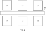
- the forming stations may be arranged in a first row.
- the lay-up stations may be arranged in a second row alongside the first row.
- the transfer mechanism may be disposed between the first and second rows.
- the transfer mechanism may be elongate along a direction in which the first and second rows extend.
- the transfer mechanism may be a linear conveyor.
- the transfer mechanism may be operable in two directions, to move pieces from either end of the first row towards the respective opposite end of the second row.
- the controller may be configured to cause the forming stations to form pieces and cause the transport mechanism to transport those pieces so as to cause the pieces to be made available in the first and second sequences to the first and second lay-up stations respectively.
- the controller may be configured to vary the direction in which pieces are conveyed by the transfer mechanism so as to cause the pieces to be made available in the first and second sequences to the first and second lay-up stations respectively.
- the controller may be configured to cause the forming stations to place the formed pieces in non-overlapping fashion on the transfer mechanism.
- the controller may be configured to cause multiple ones of the forming stations to simultaneously form multiple pieces of the first sequence.
- the controller may be configured to cause multiple ones of the forming stations to simultaneously form multiple pieces of the first and second sequences.
- the facility may comprise one or more stations configured for infusing resin into a stack of the pieces.
- At least one of the forming stations may be capable of cutting the pieces from a feedstock of a laminar reinforcement material.
- the transfer mechanism may comprise a first manipulator located so as to be capable of picking up formed pieces at a forming station and a second manipulator located so as to be capable of laying up formed pieces at a lay-up station, the second manipulator being located so that it can grip a formed piece being held by the first manipulator.
- the controller may be configured to cause one or both of the first and second manipulators to invert a formed piece so as to cause it to be laid up in the opposite orientation about a horizontal axis to the orientation in which it is formed.
- the said formed piece may be the first or last piece of a stack of pieces.
- the said piece may be the uppermost or lowermost of such a stack.
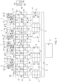
- Figure 1 illustrates an example layout for a manufacturing plant.
- the plant is configured to cut pieces from generally laminar feedstock (e.g. from rolls of pliable, woven reinforcing fibre sheet) and to lay those pieces up in overlapping fashion to collectively form reinforcement for a composite component.
- the plant is arranged so that multiple pieces can be cut and laid up simultaneously.
- the transport mechanism is a conveyor belt.
- the cutting stations are arranged in a row.
- the lay-up stations are arranged in a row.
- the transport mechanism extends between those rows to distribute cut pieces of reinforcement to the lay-up stations. This can result in a highly efficient process, particularly when components or sub-components of many different types, and material sequences, are to be made.
- the rows may be straight or curved.
- the plant of figure 1 is intended for manufacturing composite components.
- the components are made by the following steps.
- workflow is from the upper part of figure 1 to the lower part.
- the workstations shown in figure 1 comprise cutting stations 1, a mat distribution station 2, lay-up stations 3, double diaphragm forming (DDF) stations 4, assembly stations 6, and a resin infusion station 8.
- DDF double diaphragm forming
- each cutting station has a feed roll 10 of fibre sheet material.
- the material extends over a cutting table 11 to a take-up roll 12.
- the take-up roll can be driven by a motor to advance the material over the table.
- a cutting head 13 is movable over the table.
- the cutting head has a cutting device for cutting the fibre material.
- the cutting device could be a knife, a laser or an abrasive beam unit.
- the cutting head is movable under computer control to cut the sheet on the table into mats of a predetermined shape. Once the sheet on the table has been cut, it can be advanced on to the take-up roll to expose fresh fabric on the table.
- the computer that controls the cutting station is shown at 90.
- Each cutting station may hold a different feedstock from any one or more of the other cutting stations, or from all the other cutting stations; or two or more of the cutting stations may hold the same feedstock.
- the feedstock provided at each cutting station can be chosen so that collectively the cutting stations are capable of providing all the materials needed to form the mats intended to make up the final product. Once the constituent materials of the mats of the final product have been determined, rolls 10 of suitable feedstocks to form that final product can be installed at the cutting stations. If the plant is intended to form multiple final products then feedstocks sufficient to make all those products can be installed at the cutting stations.
- the cutting head could be movable over the table by being mounted on a beam 14 which can traverse the table in the direction between the feed and take-up rolls.
- the head could be mounted on the beam in such a way that it can move along the length of the beam. Motors could be provided to move the beam and to move the head on the beam.
- Each cutting station has a manipulator 15.
- it could be a manipulator having multiple linear and/or rotational degrees of freedom.
- the manipulators are robot arms.
- Each robot arm is configured so as to be capable of picking up cut mats from its cutting table and placing the mats on a distribution belt 20 at the mat distribution station 2.
- the robot arm may have jaws at its distal end for engaging cut mats. More generally, the jaws could be any suitable gripping end effector, for example a mechanical gripper, a hook or prong or a vacuum gripper.
- Each robot arm may be provided with multiple pairs of jaws. Robots for moving mats from the cutting tables to the transfer mechanism could be shared between cutting stations.
- the cutting stations are arranged side-by side.
- the row of cutting stations extends generally linearly.
- the distribution belt 20 extends along, and preferably adjacent to, the row of cutting stations, so that each of the robot arms 15 can distribute mats on to the belt.
- the distribution belt is capable of being driven to move along its length by a drive unit 21.
- the drive unit 21 can drive the belt to move in either direction.
- the distribution belt is an endless belt.
- it could be a reciprocating table.
- it could be provided by a series of hangers each mounted on an endless loop, and individual mats could be clasped by a respective hanger.
- it could be provided by a series of tables, and individual tables could carry individual mats or group of mats whilst each table could be powered independently and move independently from other tables and in both directions.
- the transport mechanism provides an upward facing and/or generally horizontal surface on which mats can be supported. That surface may be movable horizontally along the rows of the cutting and/or lay-up stations.
- lay-up stations 3 Also arranged along the distribution belt are the lay-up stations 3. Each lay-up station has a lay-up table 30. A series of lay-up manipulators 31 are located so that they can pick up mats from the distribution belt and position them on one the lay-up tables. In this example the manipulators 31 are robot arms. In order to lay up the mats to form a specific sub-element, one of the robots 31 picks up the mats to form that element in turn and lays them up in a stack on one of the lay-up tables. This involves selecting the appropriate mats from the belt, turning them each into the appropriate orientation and then putting them down on the lay-up table in the appropriate translational relationship relative to the other mats of the stack. Robots for moving mats from the transfer mechanism to the lay-up stations could be shared between lay-up stations.
- An adhesive preferably a weak tackifier, may be dispensed between layers of the stack to help hold the mats in place relative to each other. Adhesive may be pre-applied to one or both sides of some or all of the mats.
- the material(s) from which all the mats of a stack are made is/are coated before the lay-up process begins on only a single side with an adhesive.
- each cut mat has a coating of adhesive on one side, and is substantially free of adhesive on its other side.
- the mats are laid up so that there is a layer of the pre-applied adhesive between the fibre material of each mat and the fibre material of the adjacent mat(s).
- This arrangement provides a convenient way of holding the stack together.
- the stack will be built upwards from a mat whose lower surface is substantially free of adhesive. If all the layers of the stack have the same orientation and are all pre-coated with adhesive then an end surface of the stack will carry exposed adhesive.
- both end faces can be substantially free of adhesive.
- One way to achieve this is for the mat on one end face to not be pre-coated with adhesive. However, that may require it to be formed of a different material from other layers of the stack.
- Another approach is to invert one or more of the uppermost layers of the stack relative to the other layers of the stack. Conveniently only the upper layer is inverted. It is preferred not to store the upper layer mat in the inverted configuration since then it might stick to a surface on which it is resting prior to lay-up.
- a convenient approach is to position the manipulator 31 of the lay-up station sufficiently close to the manipulator 15 of a cutting station that the manipulator 31 can grip a mat that is being suspended by the manipulator 15.
- the lay-up manipulator 31 can take hold of a mat being held by the cutting manipulator 15 without the mat resting on a surface. This allows one or both of the manipulators to conveniently invert the mat before placing it on the stack, without the mat having rested on a surface in the inverted configuration.
- the stack is moved to a double diaphragm forming (DDF) station 4.
- DDF diaphragm forming
- the purpose of the DDF station is to implement an initial forming of the stack into roughly the shape it is to adopt in the final component. It does this by drawing the stack against a rigid former in DDF unit 40 in the presence of heat, and then cooling the stack. The heat causes an adhesive present in the stack to set, fixing the stack in the shape imposed by the rigid former.
- the adhesive may be pre-impregnated into the fabric from which the mats are cut, or it may be applied to the cut mats before or after laying up.
- the sub-elements may have different shapes.
- the DDF station may be provided with a library of rigid formers, indicated at 41. When a particular sub-element is to be formed, the appropriate former can be picked from the library and installed in a DDF unit.
- the resulting sub-element can be removed from the DDF unit. This may be done by another robot (not shown in figure 1 ) or manually.
- the formed sub-elements may be stored in a holding area 5.
- the sub-elements will be formed into the final component in a moulding station 8. Before that is done, the sub-elements are assembled together in or on a rigid mould element. This can be done at assembly station 6. For example, in the case of a vehicle tub, there may be sub-elements for the floor pan, the front bulkhead, the rear bulkhead, the sills and a transverse bulkhead. Having been formed separately, these sub-elements can be brought together at station 6 in a mould sized to form the entire tub.
- the mould is transported by a carrier system 7 to the moulding station 8.
- the moulding station may, for example, employ resin transfer moulding (RTM).
- RTM resin transfer moulding
- the mould volume containing the sub-elements may be closed, and then a vacuum may be drawn in the mould volume.
- resin may be injected into the mould volume. Once the resin is fully injected the moult may be heated to cause the resin to harden.
- the resulting component can be removed from the mould.
- the stations may operate under the control of a computer 90.
- the computer comprises a program memory 91, a processor 92 and a design memory 93.
- the program memory stores in a non-transient way code executable by the processor 92 to cause the computer 90 to perform its functions.
- the design memory 93 stores in a non-transient way information defining the shapes of the mats to be cut, which materials they are to be cut from, and how they are to be laid up to form stacks (i.e. in which order and their relative orientation and position) and for which sub-elements.
- the final component may be formed of a substantial number of sub-elements: for example more than 10, 20 or 30 sub-elements. To allow these to be formed efficiently, without excessive storage of cut mats or sub-elements, the system can operate in the following way.
- the controller reads from memory 93 the sequences of materials to be used to lay-up those elements/sub-elements.
- the controller has knowledge of the relative positions of the cutting stations and the lay-up stations. That knowledge may be pre-programmed into memory 93.
- the controller also has knowledge of which cutting station has access to which material. That knowledge may be pre-programmed into memory 93 or the controller may have caused the respective cutting stations to be loaded with the materials required to make the desired elements/sub-elements.
- the controller determines which lay-up stations are to lay up which of the elements/sub-elements. This may be done programmatically by the controller, e.g.
- the controller 93 then executes a program stored in the program memory 91 to determine the order in which the cutting stations should cut mat parts to form the elements/sub-elements, and the direction and distance the transport mechanism should convey those parts to distribute them to the appropriate lay-up stations. It does this in dependence on the relative locations of the cutting stations and the lay-up stations, the materials available at respective cutting stations, the lay-up stations to which particular elements/sub-elements have been allocated and the sequences of materials in the desired elements/sub-elements. This may result in multiple parts being cut simultaneously on different cutting stations, optionally from different materials.
- One input to the controller 93 may be an indication of the demand for particular cut mat parts from downstream components of the process. This may be determined in advance from production planning, or it may be generated during operation, for example in response to a defective cut mat part being rejected by a downstream process, resulting in a demand for a replacement part. If that were to happen then the controller may schedule repeat production of the rejected item. In this way the system can implements a lean manufacturing system, manufacturing only those cut parts that are required, and at the required times. It may result in multiple parts being transported simultaneously on the transport mechanism in a direction from the station where they were cut towards a lay-up station where they will be unloaded from the transport mechanism and laid up. This can result in efficient operation of the plant since cutting, lay-up and transport for different elements/sub-elements can take place simultaneously.
- the cutting stations are shared between the lay-up stations. Material from each cutting station can be distributed automatically to multiple lay-up stations.
- Multiple cut mats may be on the transfer belt 20 at the same time.
- the transfer belt shifts to the left as shown in figure 1 , it can simultaneously transport cut mats from multiple cutting stations towards multiple lay-up stations.
- the controller 90 can cause multiple ones of the cutting stations to cut mats at the same time, and to load them on to the belt so they are simultaneously on the belt. With correct ordering of the cutting tasks cut mats can be conveyed to the lay-up stations to arrive in the desired order without the transfer belt 20 having to make a separate movement for each cut mat. This means that the cutting stations can be operating at a high duty cycle.
- the cut mats arrive at a lay-up station in the order in which they are to be stacked, the lowest mat in the stack arriving first.
- utilisation of the cutting stations may be maximised by delivering the cut mats to the lay-up station out of that order.
- the robot at the lay-up station to pick the out-of-order mat from the transfer belt and store it temporarily on the lay-up table at a location offset from the existing stack until it is required. Then it can be picked up from the table and moved onto the stack.
- Another option is for the robot at the lay-up station to leave the cut mat on the transfer belt until it is needed.
- the controller 90 maintains a record of which cut mat is at which location on the belt, and the positional configuration of the belt. This allows the controller to (a) cause the robots at the cutting stations to place newly cut mats at vacant locations on the transfer belt and (b) direct the robots at the lay-up stations to pick the cut mats from the appropriate location on the belt.
- the controller directs the cutting stations, the lay-up stations and the transfer belt to cut and position mats so that lay-up can take place at multiple lay-up stations simultaneously.
- Stacks for forming different sub-elements may be being formed on different lay-up tables at the same time. If the lay-up table is large enough relative to a stack, multiple stacks could be formed on a lay-up table at the same time.
- the controller can direct the following steps:
- the cutting stations can be simultaneously cutting mats for different stations, which will in due course be moved to the lay-up stations by the transfer belt.
- the shapes of mat cut at each step may be the same or different.
- the controller may be pre-programmed with the sequence of cutting and belt movement operations needed to efficiently form the mats and transport them to the lay-up stations. Alternatively, it could be programmed to determine a suitable or efficient sequence of cutting and belt movements from knowledge of the materials available at the cutting stations, their relative positions along the belt, and the sequence of materials required to lay up each required sub-component.
- the controller may be implemented by a single computer or may be distributed between multiple computers.
- the materials used in the process may be of any suitable form.
- the mats may be of a fibre having a high tensile strength.
- the mats may comprise, for example, glass fibre, carbon fibre, polymer fibre (e.g. an aramid fibre).
- the matrix may comprise a polymer such as epoxy.
- Fibres comprising the mats may be woven, knitted, welded or glued together to form the mats.
- the mats may optionally be pre-impregnated with an adhesive.
- the mats at each cutting station may be the same, or may differ in any one or more of weight (i.e. weight per unit area), thickness, tensile strength, stiffness and relative orientation of the constituent fibres thereof.
- the shaping process performed after lay-up may be double-diaphragm forming, single-diaphragm forming, flop moulding, pressing or any other suitable process. Or that shaping process may be omitted.
- the moulding process may be resin transfer moulding or any other suitable moulding process.
- transfer belts 20 there may be multiple transfer belts 20 within reach of the robot arms at the cutting and lay-up stations. In one operating mode, one such belt could travel in one direction and the other such belt could travel in the opposite direction, for at least part of the time when the plant is operational. This may allow for particularly efficient scheduling of the cutting operations.
- the transfer of the mats from cutting stations to lay-up stations could be provided by trollies, mobile robots or robot arms, air tables or a series of movable hangers on which mats can be suspended. The movable hangers could move along a linear path.
- cut mats it is convenient for the cut mats to be laid up on horizontal tables, but they could be laid up in overlapping fashion in other ways, for example by being pinned on to upstanding walls or hung from a common hanger.
- the cutting stations form the mat pieces that are to be laid up by cutting them from sheets or rolls of material. More generally, the cutting stations can be considered to be forming stations, and the mat pieces could be formed in other ways.
- the mat pieces, or material blanks could be formed in other ways. For example, they could be laid up, woven, knitted or stitched together on demand by a forming station.
- the forming station could employ an additive layup technology such as tailored fibre placement, 3D weaving, automated fibre placement or automated tape laying.
- the individual mats are formed into sub-components and the sub-components are assembled together to form an overall component.
- the mats could be assembled directly to form the overall component.
Landscapes
- Engineering & Computer Science (AREA)
- Mechanical Engineering (AREA)
- Chemical & Material Sciences (AREA)
- Composite Materials (AREA)
- Robotics (AREA)
- Textile Engineering (AREA)
- Moulding By Coating Moulds (AREA)
Claims (15)
- Fertigungsanlage für Verbundartikel, umfassend:eine Vielzahl von Formstationen (1), wobei jede Formstation in der Lage ist, Teile aus einem Ausgangsmaterial eines laminaren Verstärkungsmaterials (10) zu formen;eine Vielzahl von Auflegestationen (3), wobei jede Auflegestation in der Lage ist, einen Stapel der geformten Teile überlappend anzuordnen;ein Transfermechanismus (2), ausgebildet zum gleichzeitigen Transportieren von geformten Teilen von mehreren der Formstationen zu mehreren der Auflegestationen (3), wobei der Transfermechanismus (2) ein Förderband ist;einen Schneidmanipulator (15) für jede Formstation (1), wobei jeder Schneidmanipulator (15) in der Lage ist, geformte Teile von der Formstation (1) aufzunehmen und geformte Teile auf dem Transfermechanismus (2) zu platzieren;eine Vielzahl von Auflegemanipulatoren (31), wobei jeder Auflegemanipulator (31) derart angeordnet ist, dass der Auflegemanipulator (31) geformte Teile von dem Transfermechanismus (2) aufnehmen und sie auf einer der Auflegestationen (3) positionieren kann;ein Speicher (93), der eine erste Folge von Teilen speichert, die auf einer ersten der Auflegestationen abzulegen sind, und eine zweite Folge von Teilen, die auf einer zweiten der Auflegestationen abzulegen sind; undeine Steuerung (90), die mit den Formstationen (1), den Auflegestationen und dem Transfermechanismus zum Steuern der Vorgänge derselben gekoppelt ist, wobei die Steuerung Zugriff auf den Speicher hat und ausgebildet ist, dass sie,wenn ein geformtes Teil der ersten Folge und ein geformtes Teil der zweiten Folge durch die Schneidmanipulatoren (15) auf den Transfermechanismus geladen werden, den Transportmechanismus veranlasst, sie gleichzeitig zu der ersten bzw. zweiten Auflegestation zu transportieren.
- Fertigungsanlage für Verbundartikel, wie in Anspruch 1 beansprucht, wobei die Formstationen (1) in einer ersten Reihe angeordnet sind, die Auflegestationen in einer zweiten Reihe neben der ersten Reihe angeordnet sind und der Transfermechanismus zwischen der ersten und der zweiten Reihe angeordnet ist.
- Fertigungsanlage für Verbundartikel, wie in Anspruch 2 beansprucht, wobei der Transfermechanismus (2) länglich entlang einer Richtung ist, in der sich die erste und zweite Reihe erstrecken.
- Fertigungsanlage für Verbundartikel, wie in Anspruch 2 oder 3 beansprucht, wobei der Transfermechanismus (2) in zwei Richtungen betrieben werden kann, um Teile von jedem Ende der ersten Reihe zu dem jeweils gegenüberliegenden Ende der zweiten Reihe zu bewegen.
- Fertigungsanlage für Verbundartikel, wie in einem der vorstehenden Ansprüche beansprucht, wobei die Steuerung (90) zum Veranlassen der Formstationen zum Formen von Teilen und zum Veranlassen des Transportmechanismus (2) zum Transportieren dieser Teile ausgebildet ist, um zu veranlassen, dass die Teile in der ersten und zweiten Folge der ersten bzw. zweiten Auflegestation zur Verfügung gestellt werden.
- Fertigungsanlage für Verbundartikel, wie in Anspruch 5 beansprucht, wobei die Steuerung (90) zum Variieren der Richtung, in der die Teile durch den Transfermechanismus (2) befördert werden, ausgebildet ist, um zu veranlassen, dass die Teile in der ersten und zweiten Folge der ersten bzw. zweiten Auflegestation zur Verfügung gestellt werden.
- Fertigungsanlage für Verbundartikel, wie in einem der vorstehenden Ansprüche beansprucht, wobei die Steuerung (90) zum Veranlassen mehrerer der Formstationen (1) zum gleichzeitigen Formen mehrerer Teile der ersten Folge ausgebildet ist.
- Fertigungsanlage für Verbundartikel, wie in einem der vorstehenden Ansprüche beansprucht, wobei die Steuerung (90) zum Veranlassen mehrerer der Formstationen (1) zum gleichzeitigen Formen mehrerer Teile der ersten und der zweiten Folge ausgebildet ist.
- Fertigungsanlage für Verbundartikel, wie in einem der vorstehenden Ansprüche beansprucht, wobei zumindest eine der Formstationen (1) in der Lage ist, die Teile aus einem Ausgangsmaterial eines laminaren Verstärkungsmaterials (10) zu schneiden.
- Fertigungsanlage für Verbundartikel, wie in einem der vorstehenden Ansprüche beansprucht, wobei der Transfermechanismus (2) einen ersten Manipulator (15), der angeordnet ist, geformte Teile an einer Formstation (1) aufzunehmen, und einen zweiten Manipulator (31), der angeordnet ist, geformte Teile an einer Auflegestation (3) abzulegen, umfasst, wobei der zweite Manipulator angeordnet ist, ein geformtes Teil zu ergreifen, das von dem ersten Manipulator gehalten wird.
- Fertigungsanlage für Verbundartikel, wie in Anspruch 10 beansprucht, wobei die Steuerung zum Veranlassen eines oder beider des ersten (15) und zweiten (31) Manipulators zum Umdrehen eines geformten Teils ausgebildet ist, um zu veranlassen, dass es in der entgegengesetzten Ausrichtung um eine horizontale Achse zu der Ausrichtung, in der es geformt wird, aufgelegt wird.
- Fertigungsanlage für Verbundartikel, wie in Anspruch 11 beansprucht, wobei das geformte Teil das erste oder letzte Teil eines Stapels von Teilen ist.
- Fertigungsanlage für Verbundartikel, wie in einem der vorstehenden Ansprüche beansprucht, wobei die Schneidmanipulatoren (15) von den Formstationen (1) gemeinsam genutzt werden.
- Fertigungsanlage für Verbundartikel, wie in einem der vorstehenden Ansprüche beansprucht, wobei die Auflegemanipulatoren (31) von den Auflegestationen (3) gemeinsam genutzt werden.
- Verfahren zur Herstellung eines Verbundartikels, umfassend:Formen einer Vielzahl von Teilen aus Ausgangsmaterialien aus laminarem Verstärkungsmaterial an jeder einer Vielzahl von Formstationen (1);gleichzeitiges Transportieren von geformten Teilen von mehreren der Formstationen in Richtung mehrerer Auflegestationen (3), wobei jede Auflegestation in der Lage ist, einen Stapel der geformten Teile überlappend anzuordnen; undAuflegen von Stapeln der geformten Teile in überlappender Weise auf die Vielzahl von Auflegestationen (3);wobei der Schritt des Transportierens mittels einer einzelnen Materialhandhabungsvorrichtung (20) durchgeführt wird;wobei die einzelne Materialhandhabungsvorrichtung (2) ein Förderband ist; undwobei ein Schneidmanipulator (15) für jede Formstation (1) in der Lage ist, geformte Teile von der Formstation (1) aufzunehmen und geformte Teile auf der einzelnen Materialhandhabungsvorrichtung (2) zu platzieren, und eine Vielzahl von Auflegemanipulatoren (31) derart angeordnet sind, dass der Auflegemanipulator (31) geformte Teile von dem Transfermechanismus aufnehmen und sie auf einer der Auflegestationen (3) positionieren kann.
Applications Claiming Priority (2)
| Application Number | Priority Date | Filing Date | Title |
|---|---|---|---|
| GB1717317.0A GB2567684B (en) | 2017-10-20 | 2017-10-20 | Composite manufacturing |
| PCT/GB2018/053037 WO2019077369A1 (en) | 2017-10-20 | 2018-10-19 | COMPOSITE MANUFACTURE |
Publications (2)
| Publication Number | Publication Date |
|---|---|
| EP3697601A1 EP3697601A1 (de) | 2020-08-26 |
| EP3697601B1 true EP3697601B1 (de) | 2024-12-18 |
Family
ID=60481830
Family Applications (1)
| Application Number | Title | Priority Date | Filing Date |
|---|---|---|---|
| EP18795776.6A Active EP3697601B1 (de) | 2017-10-20 | 2018-10-19 | Herstellung eines verbundstoffes |
Country Status (5)
| Country | Link |
|---|---|
| US (1) | US11478956B2 (de) |
| EP (1) | EP3697601B1 (de) |
| CN (1) | CN111565919B (de) |
| GB (1) | GB2567684B (de) |
| WO (1) | WO2019077369A1 (de) |
Families Citing this family (2)
| Publication number | Priority date | Publication date | Assignee | Title |
|---|---|---|---|---|
| EP3967480B1 (de) * | 2020-09-15 | 2025-12-10 | The Boeing Company | Systeme und verfahren zur formung von verbundelementen |
| CN113414999A (zh) * | 2021-06-25 | 2021-09-21 | 南通艾郎风电科技发展有限公司 | 一种风电叶片碳纤维梁制作工艺 |
Family Cites Families (14)
| Publication number | Priority date | Publication date | Assignee | Title |
|---|---|---|---|---|
| GB8305749D0 (en) * | 1983-03-02 | 1983-04-07 | British Aerospace | Tape laying apparatus |
| JP4718758B2 (ja) * | 2000-07-28 | 2011-07-06 | ハイパーカー,インコーポレイテッド | 先進的複合構造体の製造方法及び装置 |
| DE102008012255B4 (de) | 2007-03-13 | 2017-03-16 | Airbus Defence and Space GmbH | Verfahren zum Herstellen eines textilen Halbzeugs mit kraftflussgerecht verlaufenden Faserfilamenten für eine kraftflussgerechte Faserverbundstruktur |
| US8916010B2 (en) | 2007-12-07 | 2014-12-23 | The Boeing Company | Composite manufacturing method |
| US8425710B2 (en) | 2009-03-13 | 2013-04-23 | The Boeing Company | Automated placement of vibration damping materials |
| DE102010013131A1 (de) | 2009-12-21 | 2011-06-22 | REHAU AG + Co., 95111 | Verfahren zur Herstellung von endlosfaserverstärkten Formteilen aus thermoplastischem Kunststoff sowie Kraftfahrzeugformteil |
| CH704406A1 (de) | 2011-01-31 | 2012-07-31 | Kringlan Composites Ag | Verfahren zur Herstellung von Vorformen. |
| US9969131B2 (en) | 2011-06-22 | 2018-05-15 | The Boeing Company | Automated ply layup system |
| US9162434B2 (en) | 2011-07-28 | 2015-10-20 | Dieffenbacher GmbH Maschinen-und Anlagenbau | System and method for making advanced composite laminates |
| DE102011054650A1 (de) * | 2011-10-20 | 2013-04-25 | Rehau Ag + Co. | Verfahren und Vorrichtung zum Aufbauen eines Vorformlings, Formteil, Computerprogrammprodukt und Speichermedium |
| US9399338B1 (en) * | 2014-03-11 | 2016-07-26 | The Boeing Company | Systems and methods for constructing complex composite structures |
| DE102014205479B4 (de) * | 2014-03-25 | 2025-03-27 | Bayerische Motoren Werke Aktiengesellschaft | Verfahren zur Herstellung eines Faservorformlings für ein Faserverbundbauteil |
| DE102015002775A1 (de) * | 2015-03-06 | 2016-09-08 | Brötje-Automation GmbH | System zur Fertigung von Faser-Verbundbauteilen |
| US10513101B2 (en) | 2015-03-13 | 2019-12-24 | The Boeing Company | Apparatuses and methods for creating layered tape composite structures |
-
2017
- 2017-10-20 GB GB1717317.0A patent/GB2567684B/en active Active
-
2018
- 2018-10-19 US US16/757,177 patent/US11478956B2/en active Active
- 2018-10-19 CN CN201880080049.9A patent/CN111565919B/zh active Active
- 2018-10-19 EP EP18795776.6A patent/EP3697601B1/de active Active
- 2018-10-19 WO PCT/GB2018/053037 patent/WO2019077369A1/en not_active Ceased
Also Published As
| Publication number | Publication date |
|---|---|
| CN111565919B (zh) | 2023-03-21 |
| GB2567684A (en) | 2019-04-24 |
| US11478956B2 (en) | 2022-10-25 |
| GB201717317D0 (en) | 2017-12-06 |
| WO2019077369A1 (en) | 2019-04-25 |
| EP3697601A1 (de) | 2020-08-26 |
| US20200338787A1 (en) | 2020-10-29 |
| GB2567684B (en) | 2022-03-30 |
| CN111565919A (zh) | 2020-08-21 |
Similar Documents
| Publication | Publication Date | Title |
|---|---|---|
| EP3990243B1 (de) | Vorformungssystem und -verfahren | |
| CN103391841A (zh) | 生产预成形件的方法和装置 | |
| US12569886B2 (en) | Device and method for sorting plies | |
| CN111479673A (zh) | 纤维带铺设系统 | |
| EP3697601B1 (de) | Herstellung eines verbundstoffes | |
| US12097973B2 (en) | Composite wing panels and fabrication method | |
| JP2026016537A (ja) | 複合部材を製造するためのシステム及び方法 | |
| EP2536552B1 (de) | Mehrkopf-faserbestückungsvorrichtung | |
| US12202216B2 (en) | Patch material | |
| EP4000844B1 (de) | Verbundflügelplatten und herstellungsverfahren | |
| CN120418069A (zh) | 铺层系统 | |
| EP3746297B1 (de) | Herstellung von schichtprodukten | |
| CN210062090U (zh) | 用于同时敷设具有可变距离的带材的带敷设设备 | |
| NL2027396B1 (en) | Composite wing panels and fabrication method | |
| CN114516183A (zh) | 供逐层成型机使用的多道带束 | |
| KR20240176153A (ko) | 플라이 정위치 픽킹을 위한 버퍼 장치, 플라이 보관을 위한 적재 장치 및 프리폼 제조 워크셀 설비 | |
| EP4000880A1 (de) | Herstellung von gekrümmten verbundmaterialvorformen für flugzeuge über montagelinien | |
| Jarvis | Automated lay-up of composite blades |
Legal Events
| Date | Code | Title | Description |
|---|---|---|---|
| STAA | Information on the status of an ep patent application or granted ep patent |
Free format text: STATUS: UNKNOWN |
|
| STAA | Information on the status of an ep patent application or granted ep patent |
Free format text: STATUS: THE INTERNATIONAL PUBLICATION HAS BEEN MADE |
|
| PUAI | Public reference made under article 153(3) epc to a published international application that has entered the european phase |
Free format text: ORIGINAL CODE: 0009012 |
|
| STAA | Information on the status of an ep patent application or granted ep patent |
Free format text: STATUS: REQUEST FOR EXAMINATION WAS MADE |
|
| 17P | Request for examination filed |
Effective date: 20200601 |
|
| AK | Designated contracting states |
Kind code of ref document: A1 Designated state(s): AL AT BE BG CH CY CZ DE DK EE ES FI FR GB GR HR HU IE IS IT LI LT LU LV MC MK MT NL NO PL PT RO RS SE SI SK SM TR |
|
| AX | Request for extension of the european patent |
Extension state: BA ME |
|
| DAV | Request for validation of the european patent (deleted) | ||
| DAX | Request for extension of the european patent (deleted) | ||
| STAA | Information on the status of an ep patent application or granted ep patent |
Free format text: STATUS: EXAMINATION IS IN PROGRESS |
|
| 17Q | First examination report despatched |
Effective date: 20220621 |
|
| P01 | Opt-out of the competence of the unified patent court (upc) registered |
Effective date: 20230522 |
|
| GRAP | Despatch of communication of intention to grant a patent |
Free format text: ORIGINAL CODE: EPIDOSNIGR1 |
|
| STAA | Information on the status of an ep patent application or granted ep patent |
Free format text: STATUS: GRANT OF PATENT IS INTENDED |
|
| INTG | Intention to grant announced |
Effective date: 20240712 |
|
| GRAS | Grant fee paid |
Free format text: ORIGINAL CODE: EPIDOSNIGR3 |
|
| GRAA | (expected) grant |
Free format text: ORIGINAL CODE: 0009210 |
|
| STAA | Information on the status of an ep patent application or granted ep patent |
Free format text: STATUS: THE PATENT HAS BEEN GRANTED |
|
| AK | Designated contracting states |
Kind code of ref document: B1 Designated state(s): AL AT BE BG CH CY CZ DE DK EE ES FI FR GB GR HR HU IE IS IT LI LT LU LV MC MK MT NL NO PL PT RO RS SE SI SK SM TR |
|
| REG | Reference to a national code |
Ref country code: GB Ref legal event code: FG4D |
|
| REG | Reference to a national code |
Ref country code: CH Ref legal event code: EP |
|
| REG | Reference to a national code |
Ref country code: DE Ref legal event code: R096 Ref document number: 602018077757 Country of ref document: DE |
|
| REG | Reference to a national code |
Ref country code: IE Ref legal event code: FG4D |
|
| REG | Reference to a national code |
Ref country code: LT Ref legal event code: MG9D |
|
| PG25 | Lapsed in a contracting state [announced via postgrant information from national office to epo] |
Ref country code: HR Free format text: LAPSE BECAUSE OF FAILURE TO SUBMIT A TRANSLATION OF THE DESCRIPTION OR TO PAY THE FEE WITHIN THE PRESCRIBED TIME-LIMIT Effective date: 20241218 |
|
| PG25 | Lapsed in a contracting state [announced via postgrant information from national office to epo] |
Ref country code: FI Free format text: LAPSE BECAUSE OF FAILURE TO SUBMIT A TRANSLATION OF THE DESCRIPTION OR TO PAY THE FEE WITHIN THE PRESCRIBED TIME-LIMIT Effective date: 20241218 |
|
| PG25 | Lapsed in a contracting state [announced via postgrant information from national office to epo] |
Ref country code: BG Free format text: LAPSE BECAUSE OF FAILURE TO SUBMIT A TRANSLATION OF THE DESCRIPTION OR TO PAY THE FEE WITHIN THE PRESCRIBED TIME-LIMIT Effective date: 20241218 |
|
| PG25 | Lapsed in a contracting state [announced via postgrant information from national office to epo] |
Ref country code: NO Free format text: LAPSE BECAUSE OF FAILURE TO SUBMIT A TRANSLATION OF THE DESCRIPTION OR TO PAY THE FEE WITHIN THE PRESCRIBED TIME-LIMIT Effective date: 20250318 |
|
| REG | Reference to a national code |
Ref country code: NL Ref legal event code: MP Effective date: 20241218 |
|
| PG25 | Lapsed in a contracting state [announced via postgrant information from national office to epo] |
Ref country code: LV Free format text: LAPSE BECAUSE OF FAILURE TO SUBMIT A TRANSLATION OF THE DESCRIPTION OR TO PAY THE FEE WITHIN THE PRESCRIBED TIME-LIMIT Effective date: 20241218 Ref country code: GR Free format text: LAPSE BECAUSE OF FAILURE TO SUBMIT A TRANSLATION OF THE DESCRIPTION OR TO PAY THE FEE WITHIN THE PRESCRIBED TIME-LIMIT Effective date: 20250319 |
|
| PG25 | Lapsed in a contracting state [announced via postgrant information from national office to epo] |
Ref country code: RS Free format text: LAPSE BECAUSE OF FAILURE TO SUBMIT A TRANSLATION OF THE DESCRIPTION OR TO PAY THE FEE WITHIN THE PRESCRIBED TIME-LIMIT Effective date: 20250318 |
|
| PG25 | Lapsed in a contracting state [announced via postgrant information from national office to epo] |
Ref country code: NL Free format text: LAPSE BECAUSE OF FAILURE TO SUBMIT A TRANSLATION OF THE DESCRIPTION OR TO PAY THE FEE WITHIN THE PRESCRIBED TIME-LIMIT Effective date: 20241218 |
|
| PG25 | Lapsed in a contracting state [announced via postgrant information from national office to epo] |
Ref country code: SM Free format text: LAPSE BECAUSE OF FAILURE TO SUBMIT A TRANSLATION OF THE DESCRIPTION OR TO PAY THE FEE WITHIN THE PRESCRIBED TIME-LIMIT Effective date: 20241218 |
|
| PG25 | Lapsed in a contracting state [announced via postgrant information from national office to epo] |
Ref country code: PL Free format text: LAPSE BECAUSE OF FAILURE TO SUBMIT A TRANSLATION OF THE DESCRIPTION OR TO PAY THE FEE WITHIN THE PRESCRIBED TIME-LIMIT Effective date: 20241218 |
|
| PG25 | Lapsed in a contracting state [announced via postgrant information from national office to epo] |
Ref country code: ES Free format text: LAPSE BECAUSE OF FAILURE TO SUBMIT A TRANSLATION OF THE DESCRIPTION OR TO PAY THE FEE WITHIN THE PRESCRIBED TIME-LIMIT Effective date: 20241218 |
|
| PG25 | Lapsed in a contracting state [announced via postgrant information from national office to epo] |
Ref country code: IS Free format text: LAPSE BECAUSE OF FAILURE TO SUBMIT A TRANSLATION OF THE DESCRIPTION OR TO PAY THE FEE WITHIN THE PRESCRIBED TIME-LIMIT Effective date: 20250418 |
|
| PG25 | Lapsed in a contracting state [announced via postgrant information from national office to epo] |
Ref country code: PT Free format text: LAPSE BECAUSE OF FAILURE TO SUBMIT A TRANSLATION OF THE DESCRIPTION OR TO PAY THE FEE WITHIN THE PRESCRIBED TIME-LIMIT Effective date: 20250421 |
|
| PG25 | Lapsed in a contracting state [announced via postgrant information from national office to epo] |
Ref country code: EE Free format text: LAPSE BECAUSE OF FAILURE TO SUBMIT A TRANSLATION OF THE DESCRIPTION OR TO PAY THE FEE WITHIN THE PRESCRIBED TIME-LIMIT Effective date: 20241218 |
|
| PG25 | Lapsed in a contracting state [announced via postgrant information from national office to epo] |
Ref country code: RO Free format text: LAPSE BECAUSE OF FAILURE TO SUBMIT A TRANSLATION OF THE DESCRIPTION OR TO PAY THE FEE WITHIN THE PRESCRIBED TIME-LIMIT Effective date: 20241218 |
|
| PG25 | Lapsed in a contracting state [announced via postgrant information from national office to epo] |
Ref country code: SK Free format text: LAPSE BECAUSE OF FAILURE TO SUBMIT A TRANSLATION OF THE DESCRIPTION OR TO PAY THE FEE WITHIN THE PRESCRIBED TIME-LIMIT Effective date: 20241218 |
|
| PG25 | Lapsed in a contracting state [announced via postgrant information from national office to epo] |
Ref country code: SE Free format text: LAPSE BECAUSE OF FAILURE TO SUBMIT A TRANSLATION OF THE DESCRIPTION OR TO PAY THE FEE WITHIN THE PRESCRIBED TIME-LIMIT Effective date: 20241218 |
|
| REG | Reference to a national code |
Ref country code: DE Ref legal event code: R097 Ref document number: 602018077757 Country of ref document: DE |
|
| PG25 | Lapsed in a contracting state [announced via postgrant information from national office to epo] |
Ref country code: DK Free format text: LAPSE BECAUSE OF FAILURE TO SUBMIT A TRANSLATION OF THE DESCRIPTION OR TO PAY THE FEE WITHIN THE PRESCRIBED TIME-LIMIT Effective date: 20241218 |
|
| PLBE | No opposition filed within time limit |
Free format text: ORIGINAL CODE: 0009261 |
|
| STAA | Information on the status of an ep patent application or granted ep patent |
Free format text: STATUS: NO OPPOSITION FILED WITHIN TIME LIMIT |
|
| 26N | No opposition filed |
Effective date: 20250919 |
|
| PGFP | Annual fee paid to national office [announced via postgrant information from national office to epo] |
Ref country code: DE Payment date: 20251028 Year of fee payment: 8 |
|
| PGFP | Annual fee paid to national office [announced via postgrant information from national office to epo] |
Ref country code: GB Payment date: 20251007 Year of fee payment: 8 |
|
| PGFP | Annual fee paid to national office [announced via postgrant information from national office to epo] |
Ref country code: AT Payment date: 20251017 Year of fee payment: 8 |
|
| PGFP | Annual fee paid to national office [announced via postgrant information from national office to epo] |
Ref country code: IT Payment date: 20251024 Year of fee payment: 8 |
|
| PGFP | Annual fee paid to national office [announced via postgrant information from national office to epo] |
Ref country code: CZ Payment date: 20251002 Year of fee payment: 8 |
|
| REG | Reference to a national code |
Ref country code: AT Ref legal event code: UEP Ref document number: 1751939 Country of ref document: AT Kind code of ref document: T Effective date: 20241218 |