EP3697464B1 - Katheterpumpensystem und verfahren zur steuerung eines katheterpumpenantriebs - Google Patents
Katheterpumpensystem und verfahren zur steuerung eines katheterpumpenantriebs Download PDFInfo
- Publication number
- EP3697464B1 EP3697464B1 EP18812361.6A EP18812361A EP3697464B1 EP 3697464 B1 EP3697464 B1 EP 3697464B1 EP 18812361 A EP18812361 A EP 18812361A EP 3697464 B1 EP3697464 B1 EP 3697464B1
- Authority
- EP
- European Patent Office
- Prior art keywords
- catheter
- motor
- pressure
- pump
- port
- Prior art date
- Legal status (The legal status is an assumption and is not a legal conclusion. Google has not performed a legal analysis and makes no representation as to the accuracy of the status listed.)
- Active
Links
Images


Classifications
-
- A—HUMAN NECESSITIES
- A61—MEDICAL OR VETERINARY SCIENCE; HYGIENE
- A61M—DEVICES FOR INTRODUCING MEDIA INTO, OR ONTO, THE BODY; DEVICES FOR TRANSDUCING BODY MEDIA OR FOR TAKING MEDIA FROM THE BODY; DEVICES FOR PRODUCING OR ENDING SLEEP OR STUPOR
- A61M60/00—Blood pumps; Devices for mechanical circulatory actuation; Balloon pumps for circulatory assistance
- A61M60/50—Details relating to control
- A61M60/508—Electronic control means, e.g. for feedback regulation
- A61M60/562—Electronic control means, e.g. for feedback regulation for making blood flow pulsatile in blood pumps that do not intrinsically create pulsatile flow
-
- A—HUMAN NECESSITIES
- A61—MEDICAL OR VETERINARY SCIENCE; HYGIENE
- A61M—DEVICES FOR INTRODUCING MEDIA INTO, OR ONTO, THE BODY; DEVICES FOR TRANSDUCING BODY MEDIA OR FOR TAKING MEDIA FROM THE BODY; DEVICES FOR PRODUCING OR ENDING SLEEP OR STUPOR
- A61M60/00—Blood pumps; Devices for mechanical circulatory actuation; Balloon pumps for circulatory assistance
- A61M60/40—Details relating to driving
- A61M60/403—Details relating to driving for non-positive displacement blood pumps
- A61M60/408—Details relating to driving for non-positive displacement blood pumps the force acting on the blood contacting member being mechanical, e.g. transmitted by a shaft or cable
- A61M60/411—Details relating to driving for non-positive displacement blood pumps the force acting on the blood contacting member being mechanical, e.g. transmitted by a shaft or cable generated by an electromotor
- A61M60/414—Details relating to driving for non-positive displacement blood pumps the force acting on the blood contacting member being mechanical, e.g. transmitted by a shaft or cable generated by an electromotor transmitted by a rotating cable, e.g. for blood pumps mounted on a catheter
-
- A—HUMAN NECESSITIES
- A61—MEDICAL OR VETERINARY SCIENCE; HYGIENE
- A61M—DEVICES FOR INTRODUCING MEDIA INTO, OR ONTO, THE BODY; DEVICES FOR TRANSDUCING BODY MEDIA OR FOR TAKING MEDIA FROM THE BODY; DEVICES FOR PRODUCING OR ENDING SLEEP OR STUPOR
- A61M60/00—Blood pumps; Devices for mechanical circulatory actuation; Balloon pumps for circulatory assistance
- A61M60/10—Location thereof with respect to the patient's body
- A61M60/122—Implantable pumps or pumping devices, i.e. the blood being pumped inside the patient's body
- A61M60/126—Implantable pumps or pumping devices, i.e. the blood being pumped inside the patient's body implantable via, into, inside, in line, branching on, or around a blood vessel
- A61M60/13—Implantable pumps or pumping devices, i.e. the blood being pumped inside the patient's body implantable via, into, inside, in line, branching on, or around a blood vessel by means of a catheter allowing explantation, e.g. catheter pumps temporarily introduced via the vascular system
-
- A—HUMAN NECESSITIES
- A61—MEDICAL OR VETERINARY SCIENCE; HYGIENE
- A61M—DEVICES FOR INTRODUCING MEDIA INTO, OR ONTO, THE BODY; DEVICES FOR TRANSDUCING BODY MEDIA OR FOR TAKING MEDIA FROM THE BODY; DEVICES FOR PRODUCING OR ENDING SLEEP OR STUPOR
- A61M60/00—Blood pumps; Devices for mechanical circulatory actuation; Balloon pumps for circulatory assistance
- A61M60/10—Location thereof with respect to the patient's body
- A61M60/122—Implantable pumps or pumping devices, i.e. the blood being pumped inside the patient's body
- A61M60/126—Implantable pumps or pumping devices, i.e. the blood being pumped inside the patient's body implantable via, into, inside, in line, branching on, or around a blood vessel
- A61M60/135—Implantable pumps or pumping devices, i.e. the blood being pumped inside the patient's body implantable via, into, inside, in line, branching on, or around a blood vessel inside a blood vessel, e.g. using grafting
- A61M60/139—Implantable pumps or pumping devices, i.e. the blood being pumped inside the patient's body implantable via, into, inside, in line, branching on, or around a blood vessel inside a blood vessel, e.g. using grafting inside the aorta, e.g. intra-aortic balloon pumps
-
- A—HUMAN NECESSITIES
- A61—MEDICAL OR VETERINARY SCIENCE; HYGIENE
- A61M—DEVICES FOR INTRODUCING MEDIA INTO, OR ONTO, THE BODY; DEVICES FOR TRANSDUCING BODY MEDIA OR FOR TAKING MEDIA FROM THE BODY; DEVICES FOR PRODUCING OR ENDING SLEEP OR STUPOR
- A61M60/00—Blood pumps; Devices for mechanical circulatory actuation; Balloon pumps for circulatory assistance
- A61M60/10—Location thereof with respect to the patient's body
- A61M60/122—Implantable pumps or pumping devices, i.e. the blood being pumped inside the patient's body
- A61M60/165—Implantable pumps or pumping devices, i.e. the blood being pumped inside the patient's body implantable in, on, or around the heart
- A61M60/17—Implantable pumps or pumping devices, i.e. the blood being pumped inside the patient's body implantable in, on, or around the heart inside a ventricle, e.g. intraventricular balloon pumps
- A61M60/174—Implantable pumps or pumping devices, i.e. the blood being pumped inside the patient's body implantable in, on, or around the heart inside a ventricle, e.g. intraventricular balloon pumps discharging the blood to the ventricle or arterial system via a cannula internal to the ventricle or arterial system
-
- A—HUMAN NECESSITIES
- A61—MEDICAL OR VETERINARY SCIENCE; HYGIENE
- A61M—DEVICES FOR INTRODUCING MEDIA INTO, OR ONTO, THE BODY; DEVICES FOR TRANSDUCING BODY MEDIA OR FOR TAKING MEDIA FROM THE BODY; DEVICES FOR PRODUCING OR ENDING SLEEP OR STUPOR
- A61M60/00—Blood pumps; Devices for mechanical circulatory actuation; Balloon pumps for circulatory assistance
- A61M60/20—Type thereof
- A61M60/205—Non-positive displacement blood pumps
-
- A—HUMAN NECESSITIES
- A61—MEDICAL OR VETERINARY SCIENCE; HYGIENE
- A61M—DEVICES FOR INTRODUCING MEDIA INTO, OR ONTO, THE BODY; DEVICES FOR TRANSDUCING BODY MEDIA OR FOR TAKING MEDIA FROM THE BODY; DEVICES FOR PRODUCING OR ENDING SLEEP OR STUPOR
- A61M60/00—Blood pumps; Devices for mechanical circulatory actuation; Balloon pumps for circulatory assistance
- A61M60/40—Details relating to driving
- A61M60/403—Details relating to driving for non-positive displacement blood pumps
- A61M60/405—Details relating to driving for non-positive displacement blood pumps the force acting on the blood contacting member being hydraulic or pneumatic
-
- A—HUMAN NECESSITIES
- A61—MEDICAL OR VETERINARY SCIENCE; HYGIENE
- A61M—DEVICES FOR INTRODUCING MEDIA INTO, OR ONTO, THE BODY; DEVICES FOR TRANSDUCING BODY MEDIA OR FOR TAKING MEDIA FROM THE BODY; DEVICES FOR PRODUCING OR ENDING SLEEP OR STUPOR
- A61M60/00—Blood pumps; Devices for mechanical circulatory actuation; Balloon pumps for circulatory assistance
- A61M60/50—Details relating to control
- A61M60/508—Electronic control means, e.g. for feedback regulation
- A61M60/538—Regulation using real-time blood pump operational parameter data, e.g. motor current
- A61M60/554—Regulation using real-time blood pump operational parameter data, e.g. motor current of blood pressure
-
- A—HUMAN NECESSITIES
- A61—MEDICAL OR VETERINARY SCIENCE; HYGIENE
- A61M—DEVICES FOR INTRODUCING MEDIA INTO, OR ONTO, THE BODY; DEVICES FOR TRANSDUCING BODY MEDIA OR FOR TAKING MEDIA FROM THE BODY; DEVICES FOR PRODUCING OR ENDING SLEEP OR STUPOR
- A61M2205/00—General characteristics of the apparatus
- A61M2205/33—Controlling, regulating or measuring
- A61M2205/3331—Pressure; Flow
-
- A—HUMAN NECESSITIES
- A61—MEDICAL OR VETERINARY SCIENCE; HYGIENE
- A61M—DEVICES FOR INTRODUCING MEDIA INTO, OR ONTO, THE BODY; DEVICES FOR TRANSDUCING BODY MEDIA OR FOR TAKING MEDIA FROM THE BODY; DEVICES FOR PRODUCING OR ENDING SLEEP OR STUPOR
- A61M60/00—Blood pumps; Devices for mechanical circulatory actuation; Balloon pumps for circulatory assistance
- A61M60/10—Location thereof with respect to the patient's body
- A61M60/122—Implantable pumps or pumping devices, i.e. the blood being pumped inside the patient's body
- A61M60/126—Implantable pumps or pumping devices, i.e. the blood being pumped inside the patient's body implantable via, into, inside, in line, branching on, or around a blood vessel
- A61M60/148—Implantable pumps or pumping devices, i.e. the blood being pumped inside the patient's body implantable via, into, inside, in line, branching on, or around a blood vessel in line with a blood vessel using resection or like techniques, e.g. permanent endovascular heart assist devices
Definitions
- the disclosure relates to a catheter pump system and to a method of controlling a pump drive of a catheter system.
- a catheter pump which pumps blood away from the heart or from closely downstream of the heart.
- the pump function can be controlled to be pulsatile in synchronization with the beating heart, so that the flow rate at which blood is pumped is increased at the start of systole to support outflow away from the left ventricle and decreased at the start of diastole, so that the outflow of blood during systole is supported and counter pressure encountered by outflowing blood during systole is reduced and contraction of the left ventricle is facilitated.
- this object is achieved by providing a catheter pump system according to claim 1.
- an intra-aortic balloon pump is standard inventory available in virtually every hospital.
- An IABP is a balloon mounted on a catheter, which is generally inserted into the aorta through the femoral artery in the leg.
- the balloon is usually guided into the descending aorta to a position at approximately 2 cm from the left subclavian artery.
- the balloon is inflated, augmenting coronary perfusion and at the beginning of systole (when the heart ejects blood from the left ventricle through the aortic valve), the balloon is deflated so that the heart can discharge blood more easily.
- overall cardiac output is increased and the left ventricular stroke work and myocardial oxygen requirements are decreased.
- Connecting the pressure sensing port of the motor controller to the output port of an IABP driver provides a simple and reliable solution for controlling pulsatile operation of the motor and the pump in sync with pulsations of the heart, such that blood flow out of the heart is supported primarily during systole.
- control of motor speed is achieved in a particularly simple, reliable and smooth manner, regardless whether timing signals for the pulsatile operation of the motor and the pump are obtained from an IABP driver output port, if the motor is a pneumatic motor and motor control is achieved in response to control signals by a variable restriction valve reducing flow through the supply channel and allowing an increase of flow through the supply channel in response to control signals received via the input interface.
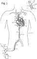
- a catheter pump system 1 has catheter 2 for insertion into a patient 3.
- the catheter 2 can be brought into a position extending through an opening 4 made in the patient body, an external iliac artery 5 and an Aorta 6 of the patient 3.
- the catheter 2 preferably has an insertable length of at least 40 cm (more preferably at least 50 cm) and at most-90 cm (more preferably at most 75 cm).
- the catheter may for instance be of a 7 to 9 Fr. thickness. Insertion into the aorta via a subclavian artery 20 is also possible.
- the insertable length can then be shorter e.g. by 10-20 cm.
- a distal end portion of the catheter 2 is located in a position extending through an aortic valve 7 of the patient 3. In some cases a position of the distal end 8 of the catheter 2 near the aortic valve 7 of the patient 3 can be sufficient.
- the catheter 2 has an inlet port 9 near the distal end 8 and an outlet port 10 proximally of the inlet port 9.
- the inlet port may also be located at the distal end of the catheter, but if, as in the present example, the catheter 2 has an end portion 11 that is more flexible than a proximally adjacent section of the catheter 2 and curved for facilitating navigating the catheter tip into position, a position of the inlet port 9 at 1-3 cm from the catheter tip 8 is particularly practical.
- the outlet port 10 communicates with the inlet port 9 via a blood flow channel 12.
- the pump system 1 further includes a pump 13 having a fluid displacement member 14 in the blood flow channel 12 and a motor 15 coupled to the pump 13 for driving the pump 13.
- a motor controller 16 is provided for controlling motor speed.
- the motor controller 16 has a pressure sensing port 18 for connection to a control pressure source 17 which generates a pressure that varies in sync with pulsations of the heart 19.
- the motor controller 16 is arranged for causing motor speed to be increased in response to a reduction of pressure applied to the pressure sensing port 18 and for causing motor speed to be reduced in response to an increase of pressure applied to the pressure sensing port 18.
- the inlet port 9 is in a left ventricle 35 of the patient 2 or, alternatively, closely downstream of the aortic valve 7 of the patient 2 and the outlet port 10 is downstream of the inlet port 9 and of the aortic valve 7 and communicates with the inlet port 9 via the blood flow channel 12.
- the motor 16 drives the pump 13 which is coupled to the motor 16.
- the motor controller 16 controls the speed of the motor 15.
- the source of variable pressure is provided in the form of an IABP driver 17.
- IABP drivers 17 are commonly available in hospital departments involved in the treatment of cardiac dysfunction and have a detector 21 detecting diastole and systole of the patient's heart from for instance an electrocardiogram, blood pressure or a pacemaker signal.
- the IABP driver 17 further has a pressure controller 22, a pressure source 23, a balloon port 26 in fluid communication with the pressure source 23 and for connection to an intra aortic balloon.
- the pressure source 23 includes a linear actuator 24 and a bellows 25 coupled to the actuator 24, so that the bellows 25 is expanded and compressed when the actuator 24 retracts and, respectively, expands.
- the interior of the bellows 25 communicates with balloon port 26 so that pressure applied to the balloon port 26 varies cyclically if the bellows 25 is reciprocally expanded and compressed.
- Other mechanisms for applying a variable pressure to the balloon port are also conceivable, but not described since IABP drivers are standard hospital equipment.
- the pressure controller 22 and the pressure source 23 of the IABP driver 17 are arranged for generating a balloon inflation pressure at the start of diastole and removing or at least reducing balloon inflation pressure at the start of systole as is illustrated by the IABP pressure curve in Fig. 5 .
- the motor controller 16 has a pressure sensing port 18 in fluid communication with the balloon port 26, so that the pressure applied to the pressure sensing port 18 varies in unison with the pressure applied to the balloon port 26.
- the motor controller 16 is arranged for causing the speed of the motor 15 to be increased in response to a reduction of pressure applied to the pressure sensing port 18 and for causing the speed of the motor 15 to be increased in response to a reduction of the pressure applied to the pressure sensing port 18.
- the pump flow rate increases if IABP pressure decreases and vice versa.
- a certain shift (towards in advance or as a delay) in the response of the pump flow rate variation to the IABP pressure variation may occur.
- the shift is preferably less than a quarter and more preferably less than an eighth of a full cycle.
- the motor 15 is a pneumatic motor and the motor controller 16 has a supply channel 27 extending through the motor controller 16 between an inlet 28 for connection to a pressure source 29 and an outlet 30 in fluid communication with the motor 15.
- a variable restriction valve 31 is arranged for reducing flow through the supply channel 27 in response to an increase of pressure applied to the pressure sensing port 18 and for allowing an increase of flow through the supply channel 27 in response to a reduction of pressure applied to the pressure sensing port 18. This allows control of motor speed to be achieved in a particularly simple, reliable and smooth manner.
- the motor 15 and the pump 13 are arranged for operation at a pressure difference between an inlet 32 and an outlet 33 of the motor 15 of at least 2 bars at a flow rate of at least 30 l/min (more preferably at least 2.5 bar at a flow rate of at least 40 l/min). Because an IABP driver is typically not capable of supplying such a pneumatic power, the pneumatic pressure is supplied to the motor controller 16 from a pressure source 29 that has been provided in addition to the IABP driver 17.
- the motor 15 is coupled to the pump 13 via a flexible drive shaft 34 extending through a lumen of the catheter 2 so that the motor 15 can drive the pump 13 via the flexible drive shaft 34.
- This allows the motor 15 to be located outside of the body 3 of the patient, i.e. proximally of an opening 4 made in the body 3 of the patient. Locating the motor 15 outside the body 3 of the patient is advantageous for safety reasons, because in the event of a leak in a portion of the catheter inside the patient's body 3, pressurized air would be injected into the blood of the patient. Such dangers can be reduced by using helium as a driving gas, but that would increase operating costs and complexity and still a larger leak would constitute a substantial hazard.
- the inlet port 9 and the outlet port 10 are at a mutual distance of at least 5 cm and more preferably at least 6 cm. This distance is preferably less than 10 cm.
- the motor controller 16, the motor 15 and the pump 13 are arranged for varying flow rate generated by the pump 13 from a lowest flow rate of less than 3 l/min at a difference between pressure at the outlet port 10 and pressure at the inlet port 9, as a result pumping action of the heart and the pump 13, of 80-120 mmHg.
- the motor controller 16, the motor 15 and the pump 13 are arranged for causing the flow rate generated by the pump 13 to reach a highest flow rate of at least 4 l/min (and more preferably at least 5 l/min) at a difference between pressure at the outlet port and pressure at the inlet port 9, as a result pumping action of the heart and the pump 13, of 15-90 mmHg.
- a catheter pump system in another embodiment, shown in Fig. 3 , includes a catheter 102 for insertion into a patient 3 into a position extending through the aorta 6 of the patient's body 3.
- a pneumatic motor 115 is provided for driving the pump 113 and a flexible drive shaft 134 extends through a lumen of the catheter 102.
- the drive shaft 134 couples the pump 113 to the motor 115 so that the pump 113 can be driven by the motor 115.
- the motor controller 116 for controlling motor speed has a supply channel 127 extending through the motor controller 116 between an inlet 128 for connection to a pressure source 129 and an outlet 130 in fluid communication with the motor 115.
- a variable restriction valve 131 is arranged for controlling flow through the supply channel 127 and an input interface 118 is provided for inputting control signals.
- the variable restriction valve 131 is arranged for reducing flow through the supply channel 127 and allowing an increase of flow through the supply channel 127 in response to control signals received via the input interface 118.
- the input interface 118 can for instance be connected to an apparatus 117 for sensing cardiac signals, such as an ECG (electrocardiogram) device, to a blood pressure transducer at or near the distal tip of the catheter or to a pacemaker.
- ECG electrocardiogram
- the motor controller 116 receives control signals via the input interface 118 and the variable restriction valve 131 is operated for reducing flow through the supply channel 127 and allowing an increase of flow through the supply channel 127 in response to the control signals received via the input interface 118.
- a motor controller control 216 is coupled to the balloon port 226 of an IABP driver 217 and to an electric power source 229.
- the motor 215 is a variable speed electric motor 215 and is coupled to a power output 230 of the motor controller 216 so that electric power can be supplied to the motor 215 under control of the motor controller 216.
- the motor controller 216 further has a pressure sensing port 218 coupled to a balloon port 226 of the IABP driver 217, so as to receive pressure outputted by the IABP driver 217.
- the motor 215 is coupled to the pump 213 for driving the pump. In this example, the motor 215 is arranged close to the pump 213 in a distal end portion of the catheter, i.e. inside the patient when in operation.
- the motor controller 216 controls power supply to the motor 215 so that, in response to pressure variations applied to the pressure sensing port 218 by the IABP driver 217, the motor speed increases in response to a reduction of pressure applied to the pressure sensing port 218 and the motor speed reduces in response to an increase of pressure applied to the pressure sensing port 218, in a manner as is illustrated by Fig. 5 .
- a certain time shift (advance or delay) between maximum IABP pressure and minimal flow rate generated by the pump 213 as well as between minimal IABP pressure and maximal flow rate generated by the pump 213 may occur. Such a time shift may be constant or vary over the cycle of pressure increase and reduction.
Landscapes
- Health & Medical Sciences (AREA)
- Heart & Thoracic Surgery (AREA)
- Engineering & Computer Science (AREA)
- Cardiology (AREA)
- Life Sciences & Earth Sciences (AREA)
- Public Health (AREA)
- Biomedical Technology (AREA)
- Hematology (AREA)
- Mechanical Engineering (AREA)
- Animal Behavior & Ethology (AREA)
- General Health & Medical Sciences (AREA)
- Anesthesiology (AREA)
- Veterinary Medicine (AREA)
- Vascular Medicine (AREA)
- Transplantation (AREA)
- External Artificial Organs (AREA)
- Infusion, Injection, And Reservoir Apparatuses (AREA)
- Reciprocating Pumps (AREA)
Claims (3)
- Katheterpumpensystem, umfassend:einen Katheter (2) zum Einführen in einen Patienten in eine Position, die sich durch eine Aorta des Patienten erstreckt, wobei sich ein distaler Endabschnitt des Katheters in der Nähe einer Aortenklappe des Patienten befindet oder sich durch diese erstreckt, wobei der Katheter eine Einlassöffnung (9) an oder in der Nähe eines distalen Endes und einer Auslassöffnung (10) proximal der Einlassöffnung aufweist und mit der Einlassöffnung über einen Blutflusskanal in Verbindung steht;eine Pumpe (13; 113) mit einem Flüssigkeitsverdrängungselement in dem Blutflusskanal;einen Druckluftmotor (15; 115) zum Antreiben der Pumpe;eine flexible Antriebswelle (34, 134), die sich durch den Katheter erstreckt, wobei die Antriebswelle die Pumpe mit dem Motor koppelt;gekennzeichnet durcheine Motorsteuerung (16; 116) zum Steuern der Motordrehzahl, wobei die Motorsteuerung aufweist:- einen Zufuhrkanal (27, 127), der sich durch die Motorsteuerung zwischen einem Einlass zum Anschluss an eine Druckquelle und einem Auslass in Fluidverbindung mit dem Motor erstreckt,- ein variables Drosselventil (31; 131), das zum Steuern des Durchflusses durch den Zufuhrkanal angeschlossen und angeordnet ist, und- eine Eingabeschnittstelle (118) zur Eingabe von Steuersignalen in die Motorsteuerung;wobei das variable Drosselventil (31; 131) so angeordnet ist, dass es den Durchfluss durch den Zufuhrkanal reduziert und eine Erhöhung des Durchflusses durch den Zufuhrkanal als Reaktion auf über die Eingabeschnittstelle empfangene Steuersignale ermöglicht.
- Katheterpumpensystem nach Anspruch 1, wobei die Eingabeschnittstelle (118) in Form eines Druckmessanschlusses zum Anschluss an eine Steuerdruckquelle ausgeführt ist, wobei die Motorsteuerung so angeordnet ist, dass sie eine Erhöhung der Motordrehzahl als Reaktion auf eine Verringerung des an den Druckmessanschluss angelegten Drucks bewirkt und eine Verringerung der Motordrehzahl als Reaktion auf eine Erhöhung des an den Druckmessanschluss angelegten Drucks bewirkt.
- Katheterpumpensystem nach Anspruch 1, wobei die Eingabeschnittstelle (118) mit einer Einrichtung (117) zum Erfassen von Herzsignalen, wie einer Elektrokardiogramm (EKG)-Vorrichtung, mit einem Blutdruckwandler an oder nahe der distalen Spitze des Katheters oder mit einem Herzschrittmacher verbunden ist.
Applications Claiming Priority (2)
| Application Number | Priority Date | Filing Date | Title |
|---|---|---|---|
| EP17197608.7A EP3473279B1 (de) | 2017-10-20 | 2017-10-20 | Katheterpumpensystem |
| PCT/NL2018/050691 WO2019078723A2 (en) | 2017-10-20 | 2018-10-19 | CATHETER PUMP SYSTEM AND METHOD FOR CONTROLLING CATHETER PUMP DRIVE |
Publications (2)
| Publication Number | Publication Date |
|---|---|
| EP3697464A2 EP3697464A2 (de) | 2020-08-26 |
| EP3697464B1 true EP3697464B1 (de) | 2022-03-30 |
Family
ID=60153206
Family Applications (2)
| Application Number | Title | Priority Date | Filing Date |
|---|---|---|---|
| EP17197608.7A Active EP3473279B1 (de) | 2017-10-20 | 2017-10-20 | Katheterpumpensystem |
| EP18812361.6A Active EP3697464B1 (de) | 2017-10-20 | 2018-10-19 | Katheterpumpensystem und verfahren zur steuerung eines katheterpumpenantriebs |
Family Applications Before (1)
| Application Number | Title | Priority Date | Filing Date |
|---|---|---|---|
| EP17197608.7A Active EP3473279B1 (de) | 2017-10-20 | 2017-10-20 | Katheterpumpensystem |
Country Status (5)
| Country | Link |
|---|---|
| US (1) | US11925794B2 (de) |
| EP (2) | EP3473279B1 (de) |
| JP (1) | JP7509494B2 (de) |
| ES (2) | ES2822984T3 (de) |
| WO (1) | WO2019078723A2 (de) |
Families Citing this family (32)
| Publication number | Priority date | Publication date | Assignee | Title |
|---|---|---|---|---|
| DE102018201030B4 (de) | 2018-01-24 | 2025-10-16 | Kardion Gmbh | Magnetkuppelelement mit magnetischer Lagerungsfunktion |
| DE102018207611A1 (de) | 2018-05-16 | 2019-11-21 | Kardion Gmbh | Rotorlagerungssystem |
| DE102018207575A1 (de) | 2018-05-16 | 2019-11-21 | Kardion Gmbh | Magnetische Stirndreh-Kupplung zur Übertragung von Drehmomenten |
| DE102018208550A1 (de) | 2018-05-30 | 2019-12-05 | Kardion Gmbh | Leitungsvorrichtung zum Leiten eines Blutstroms für ein Herzunterstützungssystem, Herzunterstützungssystem und Verfahren zum Herstellen einer Leitungsvorrichtung |
| DE102018208541A1 (de) | 2018-05-30 | 2019-12-05 | Kardion Gmbh | Axialpumpe für ein Herzunterstützungssystem und Verfahren zum Herstellen einer Axialpumpe für ein Herzunterstützungssystem |
| DE102018208539A1 (de) | 2018-05-30 | 2019-12-05 | Kardion Gmbh | Motorgehäusemodul zum Abdichten eines Motorraums eines Motors eines Herzunterstützungssystems und Herzunterstützungssystem und Verfahren zum Montieren eines Herzunterstützungssystems |
| DE102018208538A1 (de) | 2018-05-30 | 2019-12-05 | Kardion Gmbh | Intravasale Blutpumpe und Verfahren zur Herstellung von elektrischen Leiterbahnen |
| DE102018208549A1 (de) | 2018-05-30 | 2019-12-05 | Kardion Gmbh | Elektronikmodul für ein Herzunterstützungssystem und Verfahren zum Herstellen eines Elektronikmoduls für ein Herzunterstützungssystem |
| DE102018208899A1 (de) | 2018-06-06 | 2019-12-12 | Kardion Gmbh | Verfahren zum Ermitteln der Schallgeschwindigkeit in einem Fluid im Bereich eines implantierten, vaskulären Unterstützungssystems |
| DE102018208945A1 (de) | 2018-06-06 | 2019-12-12 | Kardion Gmbh | Analysevorrichtung und Verfahren zum Analysieren einer Viskosität eines Fluids |
| DE102018208913A1 (de) | 2018-06-06 | 2019-12-12 | Kardion Gmbh | Verfahren zum Betreiben eines implantierten, ventrikulären Unterstützungssystems |
| DE102018208929A1 (de) | 2018-06-06 | 2019-12-12 | Kardion Gmbh | Verfahren zur Bestimmung einer Strömungsgeschwindigkeit eines durch ein implantiertes, vaskuläres Unterstützungssystem strömenden Fluids |
| DE102018208892A1 (de) | 2018-06-06 | 2019-12-12 | Kardion Gmbh | Sensorkopfvorrichtung für ein minimalinvasives Herzunterstützungssystem und Verfahren zum Herstellen einer Sensorkopfvorrichtung für ein Herzunterstützungssystem |
| DE102018208936A1 (de) | 2018-06-06 | 2019-12-12 | Kardion Gmbh | Bestimmvorrichtung und Verfahren zum Bestimmen einer Viskosität eines Fluids |
| DE102018208862A1 (de) | 2018-06-06 | 2019-12-12 | Kardion Gmbh | Implantierbares, vaskuläres Unterstützungssystem |
| DE102018208933A1 (de) | 2018-06-06 | 2019-12-12 | Kardion Gmbh | Verfahren zur Bestimmung einer Strömungsgeschwindigkeit eines durch ein implantiertes, vaskuläres Unterstützungssystem strömenden Fluids |
| DE102018208879A1 (de) | 2018-06-06 | 2020-01-30 | Kardion Gmbh | Verfahren zur Bestimmung eines Fluid-Gesamtvolumenstroms im Bereich eines implantierten, vaskuläres Unterstützungssystems |
| DE102018208870A1 (de) | 2018-06-06 | 2019-12-12 | Kardion Gmbh | Verfahren zur Bestimmung eines Fluid-Volumenstroms durch ein implantiertes, vaskuläres Unterstützungssystem |
| DE102018210058A1 (de) | 2018-06-21 | 2019-12-24 | Kardion Gmbh | Statorschaufelvorrichtung zur Strömungsführung eines aus einer Austrittsöffnung eines Herzunterstützungssystems ausströmenden Fluids, Herzunterstützungssystem mit Statorschaufelvorrichtung, Verfahren zum Betreiben einer Statorschaufelvorrichtung und Herstellverfahren |
| DE102018210076A1 (de) | 2018-06-21 | 2019-12-24 | Kardion Gmbh | Verfahren und Vorrichtung zum Erkennen eines Verschleißzustands eines Herzunterstützungssystems, Verfahren und Vorrichtung zum Betreiben eines Herzunterstützungssystems und Herzunterstützungssystem |
| DE102018211297A1 (de) | 2018-07-09 | 2020-01-09 | Kardion Gmbh | Herzunterstützungssystem und Verfahren zur Überwachung der Integrität einer Haltestruktur eines Herzunterstützungssystems |
| DE102018211327A1 (de) | 2018-07-10 | 2020-01-16 | Kardion Gmbh | Laufrad für ein implantierbares, vaskuläres Unterstützungssystem |
| DE102018211328A1 (de) | 2018-07-10 | 2020-01-16 | Kardion Gmbh | Laufradgehäuse für ein implantierbares, vaskuläres Unterstützungssystem |
| DE102018212153A1 (de) | 2018-07-20 | 2020-01-23 | Kardion Gmbh | Zulaufleitung für eine Pumpeneinheit eines Herzunterstützungssystems, Herzunterstützungssystem und Verfahren zum Herstellen einer Zulaufleitung für eine Pumpeneinheit eines Herzunterstützungssystems |
| WO2020030700A1 (de) | 2018-08-07 | 2020-02-13 | Kardion Gmbh | Lagervorrichtung für ein herzunterstützungssystem und verfahren zum spülen eines zwischenraums in einer lagervorrichtung für ein herzunterstützungssystem |
| DE102018213350A1 (de) | 2018-08-08 | 2020-02-13 | Kardion Gmbh | Vorrichtung und Verfahren zur Überwachung eines Gesundheitszustands des Patienten |
| US10888644B2 (en) | 2019-02-06 | 2021-01-12 | inQB8 Medical Technologies, LLC | Intra-cardiac left atrial and dual support systems |
| NL2022660B1 (en) | 2019-03-01 | 2020-09-15 | Stichting Katholieke Univ | Heart Assist Device |
| DE102020102474A1 (de) | 2020-01-31 | 2021-08-05 | Kardion Gmbh | Pumpe zum Fördern eines Fluids und Verfahren zum Herstellen einer Pumpe |
| US12515036B2 (en) | 2020-09-14 | 2026-01-06 | Kardion Gmbh | Cardiovascular support pump having an impeller with a variable flow area |
| NL2028130B1 (en) | 2021-05-03 | 2022-11-10 | Cardiacbooster B V | Cardiac assist device with high frequency operation |
| US12502524B2 (en) | 2021-12-03 | 2025-12-23 | Kardion Gmbh | Cardiac pump with optical fiber for laser doppler |
Family Cites Families (15)
| Publication number | Priority date | Publication date | Assignee | Title |
|---|---|---|---|---|
| US4906229A (en) * | 1988-05-03 | 1990-03-06 | Nimbus Medical, Inc. | High-frequency transvalvular axisymmetric blood pump |
| JPH07265410A (ja) * | 1994-03-31 | 1995-10-17 | Terumo Corp | 大動脈内用バルーンカテーテルおよび血液補助循環装置 |
| FR2744923B1 (fr) | 1996-02-21 | 1998-05-15 | Franchi Pierre | Circuit de pilotage d'une pompe d'assistance cardiaque implantable du type a ballonnet de contrepression |
| US5833619A (en) | 1997-05-15 | 1998-11-10 | L. Vad Technology, Inc. | External blood pressure sensor apparatus and method |
| US6123725A (en) | 1997-07-11 | 2000-09-26 | A-Med Systems, Inc. | Single port cardiac support apparatus |
| US6149578A (en) | 1999-02-04 | 2000-11-21 | My-Tech, Inc. | Piston-action intra-aortic coronary assist device |
| US6228018B1 (en) | 1999-02-05 | 2001-05-08 | My-Tech, Inc. | Removable left ventricular assist device with an aortic support apparatus |
| US7229402B2 (en) * | 2001-02-09 | 2007-06-12 | Cardiac Output Technologies, Inc. | Minimally invasive ventricular assist technology and method |
| US6669624B2 (en) | 2002-03-26 | 2003-12-30 | O. Howard Frazier | Temporary heart-assist system |
| DE102010011998A1 (de) * | 2009-03-24 | 2010-09-30 | Ecp Entwicklungsgesellschaft Mbh | Fluidpumpeinrichtung |
| US8591393B2 (en) | 2011-01-06 | 2013-11-26 | Thoratec Corporation | Catheter pump |
| US8734331B2 (en) * | 2011-08-29 | 2014-05-27 | Minnetronix, Inc. | Expandable blood pumps and methods of their deployment and use |
| PL2564883T3 (pl) * | 2011-08-31 | 2014-09-30 | Fund Rozwoju Kardiochirurgii Im Prof Zbigniewa Religi | Pulsator elektropneumatyczny |
| EP2851100A1 (de) | 2013-09-20 | 2015-03-25 | Berlin Heart GmbH | Blutpumpensteuerungssystem und Verfahren zur Steuerung einer Blutpumpe |
| CA2985728C (en) | 2015-05-11 | 2024-06-11 | White Swell Medical Ltd | Systems and methods for reducing pressure at an outflow of a duct |
-
2017
- 2017-10-20 ES ES17197608T patent/ES2822984T3/es active Active
- 2017-10-20 EP EP17197608.7A patent/EP3473279B1/de active Active
-
2018
- 2018-10-19 WO PCT/NL2018/050691 patent/WO2019078723A2/en not_active Ceased
- 2018-10-19 ES ES18812361T patent/ES2919778T3/es active Active
- 2018-10-19 JP JP2020542522A patent/JP7509494B2/ja active Active
- 2018-10-19 US US16/756,772 patent/US11925794B2/en active Active
- 2018-10-19 EP EP18812361.6A patent/EP3697464B1/de active Active
Also Published As
| Publication number | Publication date |
|---|---|
| EP3473279B1 (de) | 2020-07-08 |
| US20210187274A1 (en) | 2021-06-24 |
| ES2919778T3 (es) | 2022-07-28 |
| ES2822984T3 (es) | 2021-05-05 |
| EP3697464A2 (de) | 2020-08-26 |
| US11925794B2 (en) | 2024-03-12 |
| JP7509494B2 (ja) | 2024-07-02 |
| WO2019078723A2 (en) | 2019-04-25 |
| EP3473279A1 (de) | 2019-04-24 |
| WO2019078723A3 (en) | 2019-06-13 |
| JP2021500196A (ja) | 2021-01-07 |
Similar Documents
| Publication | Publication Date | Title |
|---|---|---|
| EP3697464B1 (de) | Katheterpumpensystem und verfahren zur steuerung eines katheterpumpenantriebs | |
| EP0415949B1 (de) | Transvalvuläre, achssymmetrische hochfrequenzblutpumpe | |
| EP3818997B1 (de) | Intra-aortale doppelballonpumpenkathetervorrichtung | |
| US4080958A (en) | Apparatus for aiding and improving the blood flow in patients | |
| US9504773B2 (en) | Methods and systems for counterpulsation of blood flow to and from the circulatory system | |
| EP3566741A1 (de) | Intra-aortale doppelballonpumpenkathetervorrichtung | |
| US5891012A (en) | Coronary artery counterpulsation device and method | |
| US6149578A (en) | Piston-action intra-aortic coronary assist device | |
| CN119680094A (zh) | 双气路气源系统、双气路心脏辅助系统及使用方法 | |
| CN113769261A (zh) | 带瓣膜覆膜支架的主动脉内球囊反搏增效装置及使用方法 | |
| US12453850B2 (en) | Blood pump for supporting cardiac performance | |
| CN223504698U (zh) | 双气路气源系统及双气路心脏辅助系统 | |
| CN121265974A (zh) | 用于搏动式心室辅助装置的供气方法及供气系统 | |
| CN121197656A (zh) | 心室辅助介入系统 | |
| HK40077404B (zh) | 主动脉内双气囊驱动反搏导管装置 |
Legal Events
| Date | Code | Title | Description |
|---|---|---|---|
| STAA | Information on the status of an ep patent application or granted ep patent |
Free format text: STATUS: UNKNOWN |
|
| STAA | Information on the status of an ep patent application or granted ep patent |
Free format text: STATUS: THE INTERNATIONAL PUBLICATION HAS BEEN MADE |
|
| PUAI | Public reference made under article 153(3) epc to a published international application that has entered the european phase |
Free format text: ORIGINAL CODE: 0009012 |
|
| STAA | Information on the status of an ep patent application or granted ep patent |
Free format text: STATUS: REQUEST FOR EXAMINATION WAS MADE |
|
| 17P | Request for examination filed |
Effective date: 20200504 |
|
| AK | Designated contracting states |
Kind code of ref document: A2 Designated state(s): AL AT BE BG CH CY CZ DE DK EE ES FI FR GB GR HR HU IE IS IT LI LT LU LV MC MK MT NL NO PL PT RO RS SE SI SK SM TR |
|
| AX | Request for extension of the european patent |
Extension state: BA ME |
|
| RAV | Requested validation state of the european patent: fee paid |
Extension state: TN Effective date: 20200504 Extension state: MD Effective date: 20200504 |
|
| REG | Reference to a national code |
Ref country code: DE Ref legal event code: R079 Ref document number: 602018033101 Country of ref document: DE Free format text: PREVIOUS MAIN CLASS: A61M0001100000 Ipc: A61M0060135000 |
|
| GRAP | Despatch of communication of intention to grant a patent |
Free format text: ORIGINAL CODE: EPIDOSNIGR1 |
|
| STAA | Information on the status of an ep patent application or granted ep patent |
Free format text: STATUS: GRANT OF PATENT IS INTENDED |
|
| RIC1 | Information provided on ipc code assigned before grant |
Ipc: A61M 60/562 20210101ALI20211112BHEP Ipc: A61M 60/50 20210101ALI20211112BHEP Ipc: A61M 60/135 20210101AFI20211112BHEP |
|
| INTG | Intention to grant announced |
Effective date: 20211130 |
|
| GRAS | Grant fee paid |
Free format text: ORIGINAL CODE: EPIDOSNIGR3 |
|
| GRAA | (expected) grant |
Free format text: ORIGINAL CODE: 0009210 |
|
| STAA | Information on the status of an ep patent application or granted ep patent |
Free format text: STATUS: THE PATENT HAS BEEN GRANTED |
|
| AK | Designated contracting states |
Kind code of ref document: B1 Designated state(s): AL AT BE BG CH CY CZ DE DK EE ES FI FR GB GR HR HU IE IS IT LI LT LU LV MC MK MT NL NO PL PT RO RS SE SI SK SM TR |
|
| REG | Reference to a national code |
Ref country code: GB Ref legal event code: FG4D |
|
| REG | Reference to a national code |
Ref country code: CH Ref legal event code: EP |
|
| REG | Reference to a national code |
Ref country code: DE Ref legal event code: R096 Ref document number: 602018033101 Country of ref document: DE |
|
| REG | Reference to a national code |
Ref country code: AT Ref legal event code: REF Ref document number: 1478603 Country of ref document: AT Kind code of ref document: T Effective date: 20220415 |
|
| REG | Reference to a national code |
Ref country code: IE Ref legal event code: FG4D |
|
| REG | Reference to a national code |
Ref country code: LT Ref legal event code: MG9D |
|
| REG | Reference to a national code |
Ref country code: NL Ref legal event code: FP |
|
| REG | Reference to a national code |
Ref country code: ES Ref legal event code: FG2A Ref document number: 2919778 Country of ref document: ES Kind code of ref document: T3 Effective date: 20220728 |
|
| PG25 | Lapsed in a contracting state [announced via postgrant information from national office to epo] |
Ref country code: SE Free format text: LAPSE BECAUSE OF FAILURE TO SUBMIT A TRANSLATION OF THE DESCRIPTION OR TO PAY THE FEE WITHIN THE PRESCRIBED TIME-LIMIT Effective date: 20220330 Ref country code: RS Free format text: LAPSE BECAUSE OF FAILURE TO SUBMIT A TRANSLATION OF THE DESCRIPTION OR TO PAY THE FEE WITHIN THE PRESCRIBED TIME-LIMIT Effective date: 20220330 Ref country code: NO Free format text: LAPSE BECAUSE OF FAILURE TO SUBMIT A TRANSLATION OF THE DESCRIPTION OR TO PAY THE FEE WITHIN THE PRESCRIBED TIME-LIMIT Effective date: 20220630 Ref country code: LT Free format text: LAPSE BECAUSE OF FAILURE TO SUBMIT A TRANSLATION OF THE DESCRIPTION OR TO PAY THE FEE WITHIN THE PRESCRIBED TIME-LIMIT Effective date: 20220330 Ref country code: HR Free format text: LAPSE BECAUSE OF FAILURE TO SUBMIT A TRANSLATION OF THE DESCRIPTION OR TO PAY THE FEE WITHIN THE PRESCRIBED TIME-LIMIT Effective date: 20220330 Ref country code: BG Free format text: LAPSE BECAUSE OF FAILURE TO SUBMIT A TRANSLATION OF THE DESCRIPTION OR TO PAY THE FEE WITHIN THE PRESCRIBED TIME-LIMIT Effective date: 20220630 |
|
| REG | Reference to a national code |
Ref country code: AT Ref legal event code: MK05 Ref document number: 1478603 Country of ref document: AT Kind code of ref document: T Effective date: 20220330 |
|
| PG25 | Lapsed in a contracting state [announced via postgrant information from national office to epo] |
Ref country code: LV Free format text: LAPSE BECAUSE OF FAILURE TO SUBMIT A TRANSLATION OF THE DESCRIPTION OR TO PAY THE FEE WITHIN THE PRESCRIBED TIME-LIMIT Effective date: 20220330 Ref country code: GR Free format text: LAPSE BECAUSE OF FAILURE TO SUBMIT A TRANSLATION OF THE DESCRIPTION OR TO PAY THE FEE WITHIN THE PRESCRIBED TIME-LIMIT Effective date: 20220701 Ref country code: FI Free format text: LAPSE BECAUSE OF FAILURE TO SUBMIT A TRANSLATION OF THE DESCRIPTION OR TO PAY THE FEE WITHIN THE PRESCRIBED TIME-LIMIT Effective date: 20220330 |
|
| PG25 | Lapsed in a contracting state [announced via postgrant information from national office to epo] |
Ref country code: SM Free format text: LAPSE BECAUSE OF FAILURE TO SUBMIT A TRANSLATION OF THE DESCRIPTION OR TO PAY THE FEE WITHIN THE PRESCRIBED TIME-LIMIT Effective date: 20220330 Ref country code: SK Free format text: LAPSE BECAUSE OF FAILURE TO SUBMIT A TRANSLATION OF THE DESCRIPTION OR TO PAY THE FEE WITHIN THE PRESCRIBED TIME-LIMIT Effective date: 20220330 Ref country code: RO Free format text: LAPSE BECAUSE OF FAILURE TO SUBMIT A TRANSLATION OF THE DESCRIPTION OR TO PAY THE FEE WITHIN THE PRESCRIBED TIME-LIMIT Effective date: 20220330 Ref country code: PT Free format text: LAPSE BECAUSE OF FAILURE TO SUBMIT A TRANSLATION OF THE DESCRIPTION OR TO PAY THE FEE WITHIN THE PRESCRIBED TIME-LIMIT Effective date: 20220801 Ref country code: EE Free format text: LAPSE BECAUSE OF FAILURE TO SUBMIT A TRANSLATION OF THE DESCRIPTION OR TO PAY THE FEE WITHIN THE PRESCRIBED TIME-LIMIT Effective date: 20220330 Ref country code: CZ Free format text: LAPSE BECAUSE OF FAILURE TO SUBMIT A TRANSLATION OF THE DESCRIPTION OR TO PAY THE FEE WITHIN THE PRESCRIBED TIME-LIMIT Effective date: 20220330 Ref country code: AT Free format text: LAPSE BECAUSE OF FAILURE TO SUBMIT A TRANSLATION OF THE DESCRIPTION OR TO PAY THE FEE WITHIN THE PRESCRIBED TIME-LIMIT Effective date: 20220330 |
|
| VS25 | Lapsed in a validation state [announced via postgrant information from nat. office to epo] |
Ref country code: MD Free format text: LAPSE BECAUSE OF FAILURE TO SUBMIT A TRANSLATION OF THE DESCRIPTION OR TO PAY THE FEE WITHIN THE PRESCRIBED TIME-LIMIT Effective date: 20220330 |
|
| PG25 | Lapsed in a contracting state [announced via postgrant information from national office to epo] |
Ref country code: PL Free format text: LAPSE BECAUSE OF FAILURE TO SUBMIT A TRANSLATION OF THE DESCRIPTION OR TO PAY THE FEE WITHIN THE PRESCRIBED TIME-LIMIT Effective date: 20220330 Ref country code: IS Free format text: LAPSE BECAUSE OF FAILURE TO SUBMIT A TRANSLATION OF THE DESCRIPTION OR TO PAY THE FEE WITHIN THE PRESCRIBED TIME-LIMIT Effective date: 20220730 Ref country code: AL Free format text: LAPSE BECAUSE OF FAILURE TO SUBMIT A TRANSLATION OF THE DESCRIPTION OR TO PAY THE FEE WITHIN THE PRESCRIBED TIME-LIMIT Effective date: 20220330 |
|
| REG | Reference to a national code |
Ref country code: DE Ref legal event code: R097 Ref document number: 602018033101 Country of ref document: DE |
|
| PG25 | Lapsed in a contracting state [announced via postgrant information from national office to epo] |
Ref country code: DK Free format text: LAPSE BECAUSE OF FAILURE TO SUBMIT A TRANSLATION OF THE DESCRIPTION OR TO PAY THE FEE WITHIN THE PRESCRIBED TIME-LIMIT Effective date: 20220330 |
|
| PLBE | No opposition filed within time limit |
Free format text: ORIGINAL CODE: 0009261 |
|
| STAA | Information on the status of an ep patent application or granted ep patent |
Free format text: STATUS: NO OPPOSITION FILED WITHIN TIME LIMIT |
|
| 26N | No opposition filed |
Effective date: 20230103 |
|
| PG25 | Lapsed in a contracting state [announced via postgrant information from national office to epo] |
Ref country code: SI Free format text: LAPSE BECAUSE OF FAILURE TO SUBMIT A TRANSLATION OF THE DESCRIPTION OR TO PAY THE FEE WITHIN THE PRESCRIBED TIME-LIMIT Effective date: 20220330 Ref country code: MC Free format text: LAPSE BECAUSE OF FAILURE TO SUBMIT A TRANSLATION OF THE DESCRIPTION OR TO PAY THE FEE WITHIN THE PRESCRIBED TIME-LIMIT Effective date: 20220330 |
|
| REG | Reference to a national code |
Ref country code: CH Ref legal event code: PL |
|
| PG25 | Lapsed in a contracting state [announced via postgrant information from national office to epo] |
Ref country code: LU Free format text: LAPSE BECAUSE OF NON-PAYMENT OF DUE FEES Effective date: 20221019 |
|
| PG25 | Lapsed in a contracting state [announced via postgrant information from national office to epo] |
Ref country code: LI Free format text: LAPSE BECAUSE OF NON-PAYMENT OF DUE FEES Effective date: 20221031 Ref country code: FR Free format text: LAPSE BECAUSE OF NON-PAYMENT OF DUE FEES Effective date: 20221031 Ref country code: CH Free format text: LAPSE BECAUSE OF NON-PAYMENT OF DUE FEES Effective date: 20221031 |
|
| PG25 | Lapsed in a contracting state [announced via postgrant information from national office to epo] |
Ref country code: IE Free format text: LAPSE BECAUSE OF NON-PAYMENT OF DUE FEES Effective date: 20221019 |
|
| PG25 | Lapsed in a contracting state [announced via postgrant information from national office to epo] |
Ref country code: CY Free format text: LAPSE BECAUSE OF FAILURE TO SUBMIT A TRANSLATION OF THE DESCRIPTION OR TO PAY THE FEE WITHIN THE PRESCRIBED TIME-LIMIT Effective date: 20220330 |
|
| PG25 | Lapsed in a contracting state [announced via postgrant information from national office to epo] |
Ref country code: MK Free format text: LAPSE BECAUSE OF FAILURE TO SUBMIT A TRANSLATION OF THE DESCRIPTION OR TO PAY THE FEE WITHIN THE PRESCRIBED TIME-LIMIT Effective date: 20220330 Ref country code: HU Free format text: LAPSE BECAUSE OF FAILURE TO SUBMIT A TRANSLATION OF THE DESCRIPTION OR TO PAY THE FEE WITHIN THE PRESCRIBED TIME-LIMIT; INVALID AB INITIO Effective date: 20181019 |
|
| PG25 | Lapsed in a contracting state [announced via postgrant information from national office to epo] |
Ref country code: TR Free format text: LAPSE BECAUSE OF FAILURE TO SUBMIT A TRANSLATION OF THE DESCRIPTION OR TO PAY THE FEE WITHIN THE PRESCRIBED TIME-LIMIT Effective date: 20220330 |
|
| PG25 | Lapsed in a contracting state [announced via postgrant information from national office to epo] |
Ref country code: MT Free format text: LAPSE BECAUSE OF FAILURE TO SUBMIT A TRANSLATION OF THE DESCRIPTION OR TO PAY THE FEE WITHIN THE PRESCRIBED TIME-LIMIT Effective date: 20220330 |
|
| PGFP | Annual fee paid to national office [announced via postgrant information from national office to epo] |
Ref country code: BE Payment date: 20241021 Year of fee payment: 7 |
|
| PGFP | Annual fee paid to national office [announced via postgrant information from national office to epo] |
Ref country code: IT Payment date: 20241025 Year of fee payment: 7 |
|
| PGFP | Annual fee paid to national office [announced via postgrant information from national office to epo] |
Ref country code: NL Payment date: 20251021 Year of fee payment: 8 |
|
| PGFP | Annual fee paid to national office [announced via postgrant information from national office to epo] |
Ref country code: DE Payment date: 20251021 Year of fee payment: 8 |
|
| PGFP | Annual fee paid to national office [announced via postgrant information from national office to epo] |
Ref country code: GB Payment date: 20251022 Year of fee payment: 8 |
|
| PGFP | Annual fee paid to national office [announced via postgrant information from national office to epo] |
Ref country code: ES Payment date: 20251216 Year of fee payment: 8 |