EP3697159B1 - Anreizverfahren und system zur echtzeitadaption einer latenzkritischen anwendung in einem drahtlosen netzwerk - Google Patents
Anreizverfahren und system zur echtzeitadaption einer latenzkritischen anwendung in einem drahtlosen netzwerk Download PDFInfo
- Publication number
- EP3697159B1 EP3697159B1 EP19156914.4A EP19156914A EP3697159B1 EP 3697159 B1 EP3697159 B1 EP 3697159B1 EP 19156914 A EP19156914 A EP 19156914A EP 3697159 B1 EP3697159 B1 EP 3697159B1
- Authority
- EP
- European Patent Office
- Prior art keywords
- point value
- latency
- critical application
- latency critical
- time
- Prior art date
- Legal status (The legal status is an assumption and is not a legal conclusion. Google has not performed a legal analysis and makes no representation as to the accuracy of the status listed.)
- Active
Links
Images

Classifications
-
- H—ELECTRICITY
- H04—ELECTRIC COMMUNICATION TECHNIQUE
- H04W—WIRELESS COMMUNICATION NETWORKS
- H04W72/00—Local resource management
- H04W72/50—Allocation or scheduling criteria for wireless resources
- H04W72/535—Allocation or scheduling criteria for wireless resources based on resource usage policies
-
- H—ELECTRICITY
- H04—ELECTRIC COMMUNICATION TECHNIQUE
- H04W—WIRELESS COMMUNICATION NETWORKS
- H04W28/00—Network traffic management; Network resource management
- H04W28/16—Central resource management; Negotiation of resources or communication parameters, e.g. negotiating bandwidth or QoS [Quality of Service]
- H04W28/24—Negotiating SLA [Service Level Agreement]; Negotiating QoS [Quality of Service]
-
- H—ELECTRICITY
- H04—ELECTRIC COMMUNICATION TECHNIQUE
- H04W—WIRELESS COMMUNICATION NETWORKS
- H04W72/00—Local resource management
- H04W72/50—Allocation or scheduling criteria for wireless resources
- H04W72/54—Allocation or scheduling criteria for wireless resources based on quality criteria
Definitions
- the disclosure relates to computer networks, particularly to wireless networks, particularly to mobile networks and, more specifically, to latency critical applications provided within those networks.
- a network services exchange provider may employ a communication facility, such as a data center, in which multiple customers of the provider locate network, server, and storage gear and interconnect to a variety of telecommunications and other network service provider(s).
- Data centers may be shared by the multiple tenants having their networking equipment located within the data centers.
- IT Information Technology
- communications facilities in safe, secure hands, telecommunications, Internet, application service providers, cloud service providers, content providers, and other providers, as well as enterprises, enjoy less latency and the freedom to focus on their core business. Additionally, customers may reduce their traffic back-haul costs and free up their internal networks for other uses.
- Edge computing architectures will help to prioritize what data needs to remain on the edge to be processed by the vehicle's onboard computing power or by any computing device nearby the vehicle and what data should be relayed back to data centers for analysis. Edge data centers will serve a critical role in this network, functioning as a relay station and providing extra computing power for mission critical analytics that need to remain near end users.
- Edge computing can offer a solution to this problem.
- the heavy investment in autonomous vehicle research has been one of the reasons so many tech companies are pushing to improve and expand their edge computing architectures.
- companies can ensure that their autonomous vehicles are able to access the data they need with minimal latency to make decisions quickly.
- loT devices self-driving cars also have the ability to make their own decisions without relying on guidance from servers located in distant data centers.
- a further example scenario is given by computer games which experience lag when connecting to a central server and latency could mean the difference between victory and defeat.
- Edge computing is not a new concept, but several trends have come together to create an opportunity to turn massive amounts of machine-based data into actionable intelligence closer to the source of the data.
- Typical edge computing devices typically reside away from a centralize computing available in a cloud.
- Edge computing enables analytics and data gathering to occur at or nearby the source of the data.
- the role of edge computing to date has mostly been used to ingest, store, filter, and send data to cloud systems. Meanwhile, it is also desirable, that edge computing systems are packing more compute, storage, and analytic power to consume and act on the data nearby the end user location.
- WO 2017/169061 A1 refers to an external node which receives a transmission history relating to a first communication event of a first wireless terminal from a node inside a wireless access network.
- the external node transmits, to the node inside the wireless access network, a control request for at least one from a communication module in the node for communicating with the external node, a scheduler in the node, a data buffer disposed in the node or the first wireless terminal, and the first wireless terminal.
- This makes it possible, for example, to contribute to an improvement for adapting packet scheduling to communication for an application of a wireless terminal.
- JP 2017 017655 A refers to a control in a wireless access network which is suitable for a mobile edge computing environment. It is proposed that a wireless access network node receives a message indicative of control information which is introduced from characteristics of a wireless terminal (UE) connected to a wireless access network from a mobile edge computing (MEC) server.
- the MEC server is arranged by being connected to the wireless access network and provides at least one of a computing resource and storage resource for edge computing regarding a service or application for the wireless terminal.
- UE user equipment
- RTT roundtrip-time
- MNOs Mobile Network Operators
- a wireless interface i.e. a radio interface of a base station of a wireless network
- schedulers associated with such a base station operate according to a best effort and fair schedule approach when allocating the available resources on the wireless interface which leads to an inacceptable variance in latency and jitter for any latency critical application.
- the parallel application entitled "Real time adaption of a latency critical application” provides a possibility to identify an acceptable operating point for the latency critical application and to optimize simultaneously the spectrum utilization on the radio interface, i.e. in a respective cell served by a respective base station, accordingly.
- the latency critical application tends to always select the operating point which seems to be the best from the application's point of view and, therefore, to block respective resources. This impedes an arbitration between the applications connected to the base station via a scheduler associated with the base station.
- the present disclosure provides a method and a system with the features of the independent claims. Further embodiments are provided by the dependent claims and the description.
- the latency for an application can extremely vary in dependence on the number of connected users (i.e. user equipment), the signal quality etc. Such variance can be recognized via different mean latencies subject to location and time, and also via a respective jitter.
- latency critical applications such as driver assistance systems with the exchange of surroundings models, remote rendering and streaming of AR (artificial reality) and VR (virtual reality) applications, VR360 applications, of-floading of computer vision algorithms for drones, vehicles, robots etc. underlie the normal scheduling.
- AR artificial reality
- VR virtual reality
- VR360 applications of-floading of computer vision algorithms for drones, vehicles, robots etc.
- the occurring variance with respect to the mean latency and the jitter impede or even hinder the use of latency critical applications via the radio.
- a static allocation of resources would reduce the spectrum efficiency and, thus, increase the costs for such latency critical applications.
- a scheduler associated with a base station allocates the available resources to a latency critical application which is to be provided via the base station in accordance with the current requirements of the latency critical application, the current requirements of the latency critical application being determined and communicated by the latency critical application itself.
- the latency critical application which is hosted by a edge computing system located nearby the base station, determines in real time on the basis of a present operations status of the latency critical application at least some of the following context data: separated for uplink and downlink: a currently required latency, a maximum required latency, a currently required minimum throughput, maximum error rate, priority, desired duration or number of desired transmissions of this configuration.
- These determined context data are then sent by the at least one latency critical application in real time via an API endpoint of the edge computing system and SLRA (service layer radio application) which is implemented on both, the base station and the edge computing system, to the scheduler associated with the base station.
- SLRA service layer radio application
- the scheduler associated with the base station dynamically takes into account the determined context data received from the latency critical application hosted by the edge computing system when allocating and reserving the available resources for the latency critical application.
- the latency critical application hosted by the edge computing system provides the base station, i.e. the scheduler in real time with context sensitive parameters about the latency critical application, such as a current mean latency, the application needs at a present point in time, a maximum latency, a data rate the application needs at the present point in time and further parameters which are useful for the scheduler as reference point for the current state of the latency critical application. These parameters are provided besides other conventional parameters such as channel condition, historical throughput, packet delay, queue length, etc.
- a method is provided, the method comprising:
- Continuously optimizing means that real time changes concerning data transmission are observed and an adaption to those changes takes place whenever those changes have impact on data transmission quality.
- the at least one application is specified here as a latency critical application.
- the claimed method, system and computer readable storage medium can also be applied to near or no latency critical applications.
- Transmission is to be understood within the scope of the present disclosure in a broad sense, particularly as data transmission, i.e. as a transfer of data (a digital bitstream or a digitized analog signal) over a communication channel
- data transmission i.e. as a transfer of data (a digital bitstream or a digitized analog signal) over a communication channel
- channels can be copper wires, optical fibers, wireless communication channels, storage media and computer buses.
- wireless communication channels are considered.
- Data can be represented as electromagnetic signals, such as radiowaves, microwaves, an electrical voltage or infrared signal.
- Data can be represented as packets, frames, bits, information considering all different communication layers.
- Proximity is defined by a physical proximity (distance) and a logical proximity (hops) between the selected edge computing system and the base station.
- the reduced latency enables a new class of applications whose complex computing mechanisms can still be run on an external server (the edge computing system) and must not be run on the user equipment, i.e. the end user device, while, nevertheless, real time critical or near real time critical functions of the respective application can be realized.
- the decisive end-to-end latency is defined not only by the location of the edge computing system with respect to the user equipment, i.e. the end user device, but also by the latencies within the radio path.
- the method further comprises:
- each of the at least one latency critical applications defines for its own operation different possible operating points with accordingly different quality stages.
- Each of the at least one latency critical application determines as a function of its current status different possible operating points, each representing an allowable solution for the at least one latency critical application.
- the different operating points are assigned different quality stages for the at least one latency critical application, for example via a "graceful degradation".
- the different operating points are defined by at least some of the following requirement parameters:
- the possible operating points for the at least one application are defined beforehand by a developer.
- the aim of such determination of operating points is to perform a substitution of uncontrollable errors and states due to changed latency and throughput by a controlled reduced user experience. Is an optimal operating point for the at least one latency critical application due to a full cell or other specific cell conditions not realizable, the controlled adaption of a further allowed operating point is possible.
- Each of the possible operating points of the at least one latency critical application is assigned a priority and defined by at least one of the following parameters: minimum throughput downlink, minimum throughput uplink, maximum latency downlink, maximum latency uplink, maximum error rate, desired duration or number of desired transmissions of this configuration. Due to the assignment of respective point values to the different operating points wherein the assignment is dynamically reviewed dependent on the dynamically newly determined point value function (which may change in dependence of current cell conditions), the operating points are not only prioritized in view of their respective quality but also in view of their respective point values. Such point values can be acquired beforehand from the network provider. A respective user and/or supplier of a latency critical application can prioritize the operating points of the latency critical application with regard to quality and point value by applying, for example, an appropriate cost function.
- the possible operating points for the at least one latency critical application are listed together with the previously determined prioritization of the possible operating points in a table of operating points and are sent in real time from the respective one of the at least one latency critical application hosted by the selected edge computing system to the scheduler of the base station, the scheduler of the base station aggregates all possible operating points of all applications which are currently running via the base station, allocates the available resources accordingly and sends a feedback message to the respective one of the at least one latency critical application hosted by the selected edge computing system about the finally selected operating point for the respective one of the at least one latency critical application.
- the possible operating points are transferred together with their respective requirement parameters via the SLRA in real time to the scheduler.
- the priorities of the operating points can dynamically be altered.
- the scheduler aggregates all requirements of all latency critical applications. Then, the scheduler determines the allocation of resources for all user equipment within the cell. Thereby, the scheduler takes into account:
- the scheduler associated with the base station and the at least one latency critical application hosted by the selected edge computing system exchange iteratively information for negotiating a best adjustment of the at least one application to present data transmission conditions.
- the scheduler associated with the base station sends, as starting point of the negotiation, an initial configuration comprising at least a maximum latency and a data rate to the at least one latency critical application hosted by the selected edge computing system. It is possible that the scheduler sends further parameters.
- Such initial configuration is to be understood as a suggestion on the basis of which further negotiation is to be pursued.
- the at least one latency critical application hosted by the selected edge computing system sends, as starting point of the negotiation, an initial configuration comprising at least one operating point or a list of possible operating points with respective priorities for the at least one application as starting point of the negotiation to the scheduler associated with the base station.
- an initial configuration comprising at least one operating point or a list of possible operating points with respective priorities for the at least one application as starting point of the negotiation to the scheduler associated with the base station.
- the respective party When receiving the initial configuration the respective party, i.e. the scheduler associated with the base station or the at least one latency critical application hosted by the selected edge computing system, examines the initial configuration and accepts the initial configuration or transmits a proposal for changes to the respective other party, i.e. to the at least one latency critical application hosted by the selected edge computing system or to the base station, particularly to the scheduler associated with the base station.
- the scheduler is often forced to perform iterations as the scheduler which has to control and administrate a plurality of latency critical applications, has to determine the correct operation status, i.e. all of the plurality of latency critical applications have to be supported, i.e. supplied with resources at the best.
- the scheduler associated with the base station covering the cell sends in real time an information about such changes and/or such changing operation conditions via SLRA to the at least one latency critical application hosted by the selected edge computing system. Furthermore, the scheduler determines in real time, i.e. at a point in time T the point value function PW (L, D, T) and transfers the newly determined point value function PW (L, D, T) to the at least one latency critical application.
- the point value function PW (L, D, T) is time variable and changes dynamically dependent on a current status within the cell and/or at the user equipment (the end user device).
- the at least one latency critical application decides about a new subset of operating points which can be adopted by the latency critical application in order to adapt to the changing operation conditions in the cell at best.
- the at least one latency critical application calculates for each possible operating point via the newly received point value function PW (L, D, T) a respective new point value. In view of the respective new point values for all operating points, respectively, the at least one latency critical application weighs for each operating point a point value assigned to a respective operating point against a quality assigned to the same operating point and prioritizes the operating points in the list of operating points accordingly.
- the at least one latency critical application sends the scheduler a message via SLRA about the new subset of operating points, i.e. the newly prioritized operating points in view of the newly calculated point values for each operating point, and the scheduler selects one operating point of the new subset of operating points (considering the new prioritization of the operating points). It is to be stated that the scheduler always aims to select the operating point with the highest priority as far as possible in view of a current status on the cell.
- Such exchange of transmission specific data between the scheduler and the at least one latency critical application happens in real time with each discernable change in the cell and/or at the user equipment and/or at the at least one latency critical application.
- the proposed method it is envisaged now to consider when prioritizing the operating points of the respective one of the at least one latency critical application, not only the criteria of minimum throughput downlink, minimum throughput uplink, maximum latency downlink, maximum latency uplink, maximum error rate, desired duration or number of desired transmissions of this configuration, but also the calculated point values for the different operating points at a considered point in time T and the calculated SDP.
- a respective latency critical application only envisage to choose the operating point which is objectively and solely considered the best for said respective latency critical application.
- the point value function PW (L, D, T_N+w) which is valid at the current point in time T_N+w is determined in real time by the scheduler of the base station and transferred from the scheduler to each of the at least one latency critical application, each of which being hosted by a respective one of the at least one selected edge computing system located nearby the base station.
- scheduling unit associated with the base station is to be understood as a scheduler which can be co-located with the base station or which can be part of the base station or which can be located remotely from the base station for which it operates.
- each one of the at least one latency critical application calculates in step k) for each of its possible operating points a respective point value at the point in time T_N+w via the point value function PW (L, D, T_N+w) and prioritizes in step I) its operating points and informs the scheduler about its current prioritization of its operating points.
- the point value function PW (L, D, T) is dynamically determined for a point in time T dependent on the respective conditions on the cell at said point in time T. It is possible that the point value function is periodically determined with a specific well-defined periodic time ⁇ T. Alternatively, the point value function is only newly determined when it is stated, particularly by a control unit hosted by the base station, that the operation conditions on the cell have (discernibly) changed, i.e. when it is stated at a point in time T that the number of end user devices within the cell, i.e. the end user devices (wirelessly) connected to the base station, has increased or decreased, etc. That means that the control unit continuously observes what happens within the cell and immediately states when the operation conditions within the cell change.
- the control unit In case of changing operation conditions observed at a point in time T, the control unit immediately, i.e. in real time initiates at that point in time T that the point value function PW (L, D, T) is newly determined.
- the scheduler or a computing unit can determine the new point value function. There is a pre-given rule/algorithm on the basis of which the time variable point value function can be generated.
- the respective conditions in the cell which are analysed and observed at said point in time T are selected from the group comprising at least: number of end user devices located within the cell and channel conditions.
- the point value increases with decreasing latency and/or with increasing throughput, and the point value decreases with increasing latency and/or decreasing throughput.
- the base station and the at least one selected edge computing system hosting the at least one latency critical application are logically connected via a service layer radio application (SLRA) which is implemented on both, the base station and the at least one selected edge computing system and, thus the at least one latency application hosted by the at least one selected edge computing system communicates with the scheduler associated with the base station via SLRA.
- SLRA service layer radio application
- the selected edge computing system can be realized as cloudlet. Due to the proximity of the selected edge computing system to the scheduler, information can be transmitted between the at least one latency critical application hosted by the selected edge system and the scheduler in real time. Thereby, the at least one latency critical application at the selected edge computing system is logically connected with the radio scheduler associated with the base station via the service layer radio application (SLRA). This enables the scheduler to send and/or receive context sensitive information/parameters about the cell and/or from the at least one latency critical application via this service layer.
- SRA service layer radio application
- a vehicle driving with a low velocity can transmit periodically data such as a surroundings model with a higher maximum latency without compromising the driving safety.
- the maximum latency should be reduced when the vehicle is driving with a higher velocity in order to adapt the reaction times within the global system accordingly and to guarantee the driving security.
- applications with a high data throughput are relevant for the adaptation of the data rate, such as video based applications: a remote rendering of an AR application requires the streaming of video data.
- the data rate can be reduced or has to be increased as a function of the number of rendered objects, the size of the image area, the required resolution for the depth of detail etc.
- the present disclosure refers to a possibility to efficiently use the actual room for operation each application has, without risking to operate unconfidently.
- the scheduler can dynamically optimize the distribution and allocation of the radio resources.
- the scheduler gets more flexible when allocating and reserving the limited resources of the radio spectrum.
- the spectrum can be used/exploited more efficiently as by algorithms without knowledge of a current status of the at least one latency critical application.
- Such conventional algorithms consider latency requirements only statically and with a lowest latency or with a mean latency which leads to the above-mentioned disadvantages such as unsatisfactory and insufficient exploitation of the radio spectrum.
- the scheduler associated with the base station determines in real time at a point in time T available resources for the at least one latency critical application as a function of a current status of the cell served by the base station, taking into account all connected devices with their applications, latency critical and/or non-latency critical applications, and their requirements and the overall available resources in the cell, derives therefrom a currently attainable individual data throughput and/or a currently attainable individual latency and/or a current individual packet loss for the at least one latency critical application, and a new point value function PW (L, D, T) and sends the currently attainable individual data throughput and/or the currently attainable individual latency and/or the current individual packet loss and the new point value function to the at least one latency critical application via the SLRA and the at least one latency critical application adapts in real time accordingly.
- the application adapts to the present status of the base station by prioritizing dynamically its possible operating points on the basis of PW (L, D, T) and transferring such new list of operating points to the scheduler so that the scheduler has, due to the new prioritization, generally more room to distribute/allocate the available resources on the cell.
- the provided method enables the at least one latency critical application to adapt in real time to a current status of a radio cell which is served by the base station.
- the at least one latency critical application is running near the base station within the selected edge computing system.
- the scheduler within the base station can transmit in real time status information about the radio cell to the at least one latency critical application hosted by the selected edge computing system.
- Such status information is transmitted via the service layer radio application (SLRA) which logically connects the base station/the scheduler with the selected edge computing system and, thereby, with the at least one latency critical application.
- the scheduler determines in real time the resources which are available for the at least one latency critical application in terms of resource blocks or resource elements.
- the possible latency and the data rate on the radio for the at least one latency critical application are derivable. Further parameter, such as packet loss etc. can be determined.
- the status data "new latency”, “new data rate”, “packet loss” etc. are transmitted together with an updated point value function PW via SLRA in real time to the selected edge computing system and transferred to the at least one latency critical application.
- the at least one latency critical application can adapt now to the new status information and can capture a new appropriate operations status by taking into account respective point values calculated via the dynamically determined point value function for all possible operating points for the at least one latency critical application.
- an autonomous vehicle can reduce its velocity when the latency guaranteed by the base station, i.e. the scheduler is currently increased. Conversely, the vehicle can increase its velocity as soon as the latency is reduced. With remote rendering a higher compression rate with more image/compression artefacts can be used in order to adapt to a new data rate.
- the present disclosure further refers to a system comprising:
- the proposed system is specifically configured to execute a method with at least some of the features described before.
- the present disclosure further describes a computer readable storage medium comprising instructions that when executed cause one or more processors of a wireless network to execute a method with at least some of the features described before.
- the computer readable storage medium particularly comprises instructions that when executed cause one or more processors of a wireless network to:
- Figure 1a is a schematic diagram illustrating several reference point values of an example reference point value function PW R (L, D).
- Figure 1a shows a coordinate system with three coordinate axes 101, 102 and 103. Latency L is plotted along axis 101, data rate (throughput) D is plotted along axis 102 and a reference point value PW R as a result of the reference point value function PW R (L, D) dependent on a specific latency L and a specific data rate D is plotted along axis 103. That means that the reference point values PW R are plotted over the latency L and the data throughput D.
- the reference point value function PW R (L, D) is shown by means of several reference point values PW R 1, PW R 2, PW R 3, PW R 4, PW R 5, PW R 6 at positions 111 to 116.
- the reference point value PW R X decreases with increasing latency L and/or decreasing throughput D.
- the lowest reference point value PW R 3 at 113 is assigned to a high latency L and a small data throughput D compared with the other reference point values PW R 1 at 111, PW R 2 at 112, PW R 4 at 114, PW R 5 at 115 and PW R 6 at 116.
- the highest reference point value PW R 5 at 115 is assigned to a small latency L and a high throughput D compared with the other reference point values PW R 1 at 111, PW R 2 at 112, PW R 3 at 113, PW R 4 at 114 and PW R 6 at 116.
- the specific reference point value function PW R (L, D) is defined by the network provider (MNO).
- Figures 1b and 1c show two different use cases.
- Figure 1b shows a time variable point value function PW (L, D, T) for a near empty cell. All actual point values which are calculated for the latencies and the data rates corresponding to those of Figure 1a , respectively, i.e. at the positions 111, 112, 113, 114, 115, 116, respectively, are lower compared to the respective reference point values. This is because the reservation of resources for a small latency and a high latency is less at the expense of other users within the cell compared to a more populated cell and/or to more critical transmission conditions.
- Figure 1c shows in contrast thereto the point value function PW (L, D, T) for a full cell and/or for more critical conditions for the end user device (e.g. at an edge of the cell). All actual point values are now higher compared to the respective reference point values.
- a user determines a mean latency L AV and a mean data throughput D AV for his use case of a respective latency critical application by means of an end user device.
- a reference point value PW R for this user is calculated as PW R (L Av , D AV ) via the reference point value function PW R (L, D).
- the time variable point value function PW (L, D, T) is to be applied which considers current conditions of the end user device and/or in a respective cell which currently serves the end user device.
- the point value function PW (L, D, T) can change dependent on a current situation/current conditions within the cell.
- the point value function PW(L, D, T) assigns, at a point in time T, each tuple (L, D) consisting of latency L and throughput D to a distinct point value PW(L, D) wherein each point value represents an allocation/intensity of resource utilisation of a respective application which requires the respective latency L and the respective throughput D.
- the point value function PW (L, D, T) reflects dynamically the allocation/intensity of resource utilisation of a respective application.
- the respective application producer and/or the respective user of the application can purchase a previously fixed reference point value PW R .
- PW R is based on a mean latency and a mean throughput assumed as being required on average by the respective application.
- the difference is captured by the network provider.
- the network provider forms a sum SDP by summing up all difference points within a specific time interval, i.e.
- the sum SDP reflects a consolidated status of the allocation/intensity of resource utilisation of the respective application.
- the SDP can be settled towards the application producer or the user of the application. That means that a positive value of SDP indicates additional costs which have to be settled by the application producer and/or the user of the application.
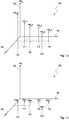
- FIG. 2 shows a flow diagram illustrating in parts an embodiment of the claimed method.
- Starting point is a wireless network of a network provider and an end user device UE_K which is located within a cell of the wireless network and which is to be provided with a latency critical application via a base station which serves the cell.
- the operating points are generally assigned to different quality levels accordingly. Further, the operating points are assigned at a point in time T to different point values of the previously described time variable point value function PW (L, D, T). Each point value can correspond to a specific monetary value. For each latency critical application the user and/or the application producer purchases in advance a previously fixed reference point value calculated via the reference point value function PW R (L, D). In the following several point values are calculated via the time variable point value function PW (L, D, T) for different points in time within a period under review and compared with the reference point value. As described with reference to Figure 1 , all resulting difference points within the period under review are summed up to form a sum SDP_K for end user K, i.e. the end user device UE_K.
- a scheduler 202 associated with the base station which supplies the cell of the cellular network with resources provides in step 211 the end user device UE_K, i.e. the latency critical application which is to be supplied to the end user device UE_K, in real time at a current point in time T_N+w with the point value function PW (L, D, T_N+w) which is valid at the current point in time T_N+w. Further, the scheduler 202 transmits the application specific sum SDP_K which has been calculated before for the period under review, i.e. for a time interval [T_N-u, T_N] with T_N being before T_N+w.
- the latency critical application can be a client based application and hosted directly by the user equipment UE_K or it can be a server based application and hosted by a server, particularly by a selected edge computing system.
- the latency critical application and/or a computing unit of a selected edge computing system hosting the latency critical application calculates for each possible operating point BP_I of the entirety of possible operating points BP_1,..., BP_Z of the latency critical application a respective point value at the current point in time T_N+w by means of the point value function PW (L, D, T_N+w). Further, the possible operating points are newly prioritized for the current point in time T_N+w by taking into account as assessment criteria not only the respective latency and the respective throughput but also the respective point value at the current point in time T_N+w and the SDP_K. A list of the possible and newly prioritized operating points is sent in step 212 to the scheduler 202 which selects in step 213 one operating point BP_X of the possible operating points and allocates the resources accordingly.
- a change takes place on the part of the end user K it is possible to transfer in a step 222 a list of newly prioritized operating points BP_1, ..., BP_Z to the scheduler 202.
- the scheduler 202 can select again in step 223 on the basis of the new list an appropriate operating point BP_Y for the latency critical application.
- the scheduler 202 calculates the point value function PW (L, D, T_N+s) which is valid at the current point in time T N+s which is after the point in time T N+w and sends the newly calculated point value function PW (L, D, T_N+s) together with the SDP_K in step 231 to the end user device, i.e. to the latency critical application hosted by the selected edge computing system.
- the latency critical application and/or the computing unit of the selected edge computing system calculates again for each possible operating point BP_I of the entirety of possible operating points BP_1,..., BP_Z of the latency critical application a respective point value at the current point in time T_N+s by means of the point value function PW (L, D, T_N+s). Further, the possible point values are newly prioritized for the current point in time T_N+s by taking into account as assessment criteria not only the respective latency and the respective throughput but also the respective point value at the current point in time T_N+s and the SDP_K.
- the latency critical application and/or the computing unit of the selected edge computing system determines again a list of newly prioritized operating points and transfers the new list in step 232 to the scheduler 202 which selects in step 233 an appropriate operating point BP_W.
- the point value function is designated in the Figure 2 generally by PW(L,D,T), although the point value function can change with time as indicated before.
- SDP_K the sum SDP which is generally designated by SDP_K.
Landscapes
- Engineering & Computer Science (AREA)
- Computer Networks & Wireless Communication (AREA)
- Signal Processing (AREA)
- Quality & Reliability (AREA)
- Mobile Radio Communication Systems (AREA)
Claims (11)
- Verfahren, umfassend:a) Bereitstellen mindestens einer latenzkritischen Anwendung, die mindestens einem Endbenutzergerät (201) in einer Zelle über eine die Zelle bedienende Basisstation bereitgestellt werden soll,b) Ermitteln der mittleren Latenz und des mittleren Durchsatzes für jede der mindestens einen latenzkritischen Anwendung, die von der jeweiligen einen der mindestens einen latenzkritischen Anwendung benötigt werden, und Zuweisen der ermittelten mittleren Latenz LAV und des mittleren Durchsatzes DAV zu einem Referenzpunktwert (PWR1, PWR2,..., PWR6), wobei der Referenzpunktwert (PWR1, PWR2,..., PWR6) mittels einer Referenzpunktwertfunktion PWR(L, D) berechnet wird, wobei die Referenzpunktwertfunktion PWR(L, D) dem Referenzpunktwert PWR(LAV, DAV) das Tupel (LAV, DAV), bestehend aus der mittleren Latenz LAV und dem mittleren Durchsatz DAV, zuweist, wobei der Referenzpunktwert (PWR1, PWR2, ..., PWR6) eine Zuordnung der Ressourcennutzung der jeweiligen mindestens einen Anwendung darstellt,c) Zuordnen des berechneten Referenzpunktwertes (PWR1, PWR2,..., PWR6) zu der jeweiligen latenzkritischen Anwendung,und, Verwendung eines mit der die Zelle bedienenden Basisstation assoziierten Schedulers zum:d) Berechnen, mittels einer zeitvariablen Punktwertfunktion PW(L, D, T), eines tatsächlichen Punktwertes PW für die jeweilige latenzkritische Anwendung auf der Grundlage der Latenz und des Durchsatzes, die aktuell von der mindestens einen latenzkritischen Anwendung benötigt werden, zu einem Zeitpunkt T_N-u innerhalb eines Zeitintervalls [T_N-u,T_N], wobei die Punktwertfunktion PW(L, D, T) jedes Tupel (L, D) (111,..., 116), bestehend aus Latenzzeit L und Durchsatz D, zu einem Zeitpunkt T einem bestimmten Punktwert PW(L, D) zuweist, wobei jeder Punktwert eine tatsächliche Zuordnung der Ressourcennutzung der jeweiligen Anwendung darstellt,e) Vergleichen des zugeordneten Referenzpunktwertes (PWR1, PWR2,..., PWR6) mit dem tatsächlichen Punktwert,f) Ermitteln eines Differenzwertes zwischen dem Referenzpunktwert (PWR1, PWR2,..., PWR6) und dem tatsächlichen Punktwert,g) Wiederholen der Schritte d) bis f) für eine Teilmenge von Zeitpunkten T_v innerhalb des Zeitintervalls [T_N-u,T_N], wobei N, u, v jeweils positive ganzzahlige Werte sind und u ≤ N und N - u ≤ v ≤ N gilt,h) Aufsummieren aller in Schritt f) ermittelten Differenzwerte für alle Zeitpunkte T_v der Teilmenge, sodass eine Summe SDP gebildet wird,i) Bereitstellen des Wertes der Summe SDP an die mindestens eine latenzkritische Anwendung,
wobeij) die mindestens eine latenzkritische Anwendung sich kontinuierlich in Echtzeit an aktuelle Übertragungsbedingungen im Netzwerk anpasst, indem sie berücksichtigt, ob die Summe SDP von Schritt h) einen positiven Wert hat, und indem sie kontinuierlich mögliche Betriebspunkte für die jeweilige latenzkritische Anwendung kontrolliert, wodurch sie die aktuelle Nutzung der Ressourcen in der Zelle optimiert, wobei ein positiver Wert der Summe SDP zusätzliche Kosten anzeigt, die verhindert werden sollen. - Verfahren nach Anspruch 1, ferner umfassend:k) Bereitstellen, durch den Scheduler, der zeitvariablen Punktwertfunktion PW(L, D, T) und der jeweiligen anwendungsspezifischen Summe SDP, die in Schritt h) für das Zeitintervall [T_N-u, T_N] berechnet worden ist, in Echtzeit zu einem Zeitpunkt T_N+w an jede der mindestens einen latenzkritischen Anwendung, wobei T_N vor T_N+w liegt und w ein positiver ganzzahliger Wert ist,I) Berechnen, durch die mindestens eine latenzkritische Anwendung, eines jeweiligen Punktwertes zum Zeitpunkt T_N+w für jeden möglichen Betriebspunkt (BP_1, BP_2, ...BP_Z) der jeweiligen mindestens einen Anwendung mittels der Punktwertfunktion PW(L, D, T_N+w);m) Priorisieren, durch die mindestens eine latenzkritische Anwendung, der Betriebspunkte (BP_1, BP_2, ...BP_Z) hinsichtlich der jeweiligen berechneten Punktwerte und der SDP;n) Zuordnen der Ressourcen durch den Scheduler zu der jeweiligen mindestens einen Anwendung gemäß der aktuellen Priorisierung;o) iteratives und/oder kontinuierliches Wiederholen der Schritte k) bis n), indem jedes Mal der Laufparameter N um 1 erhöht wird, wobei u, v, w variable positive ganzzahlige Werte sind.
- Verfahren nach Anspruch 2, wobei die Punktwertfunktion PW(L, D, T), die zum aktuellen Zeitpunkt T_N+w gültig ist, in Echtzeit von dem Scheduler (202) der Basisstation bestimmt und von dem Scheduler (202) an jede der mindestens einen latenzkritischen Anwendungen übertragen wird, die jeweils von einem entsprechenden von mindestens einem ausgewählten, in der Nähe der Basisstation befindlichen Edge-Computing-System und/oder von dem mindestens einen in der Zelle befindlichen Endbenutzergerät (201) gehostet werden.
- Verfahren nach Anspruch 3, wobei jede der mindestens einen latenzkritischen Anwendung in Schritt I) für jeden ihrer möglichen Betriebspunkte (BP_1, BP_2, ...BP_Z) mittels der Punktwertfunktion PW(L, D, T) einen jeweiligen tatsächlichen Punktwert zum Zeitpunkt T_N+w berechnet und in Schritt m) ihre Betriebspunkte (BP_1, BP_2, ...BP_Z) priorisiert und den Scheduler (202) über ihre aktuelle Priorisierung ihrer Betriebspunkte (BP_1, BP_2, ...BP_Z) informiert.
- Verfahren nach einem der vorangehenden Ansprüche, wobei die zeitvariable Punktwertfunktion PW(L, D, T) dynamisch für einen Zeitpunkt T in Abhängigkeit von den jeweiligen Zuständen in der Zelle zum Zeitpunkt T bestimmt wird.
- Verfahren nach Anspruch 5, wobei die jeweiligen Zustände in der Zelle zum besagten Zeitpunkt T aus der Gruppe ausgewählt werden, die mindestens umfasst:
Anzahl der innerhalb der Zelle befindlichen Endbenutzergeräte (201), Kanalzustände. - Verfahren nach einem der vorangehenden Ansprüche, wobei der Punktwert der zeitvariablen Punktwertfunktion mit abnehmender Latenz und/oder mit zunehmendem Durchsatz zunimmt und der Punktwert mit zunehmender Latenz und/oder abnehmendem Durchsatz abnimmt.
- Verfahren nach einem der vorangehenden Ansprüche, wobei die Basisstation und das Endbenutzergerät (201), das die mindestens eine latenzkritische Anwendung hostet, logisch über eine Service-Layer-Radio-Anwendung (SLRA) verbunden sind, die sowohl auf der Basisstation als auch auf dem Endbenutzergerät (201), das die mindestens eine latenzkritische Anwendung hostet, implementiert ist, und/oder wobei die Basisstation und mindestens ein Edge-Computing-System, das die mindestens eine latenzkritische Anwendung hostet, logisch über SLRA, das sowohl auf der Basisstation als auch auf dem mindestens einen ausgewählten Edge-Computing-System implementiert ist, verbunden sind und wobei die mindestens eine latenzkritische Anwendung mit dem mit der Basisstation assoziierten Scheduler (202) über SLRA kommuniziert.
- System, umfassend:- mindestens ein Endbenutzergerät (201), das sich in einer Zelle befindet und dem mindestens eine latenzkritische Anwendung über eine die Zelle bedienende Basisstation bereitgestellt wird,das System weiterhin umfassend:- einen Scheduler (202), der mit der die Zelle bedienenden Basisstation assoziiert ist,- die mindestens eine latenzkritische Anwendung,wobei das mindestens eine Endbenutzergerät (201) dazu konfiguriert ist, mit dem Scheduler (202) zu kommunizierten, der mit der die Zelle bedienenden Basisstation assoziiert ist,
wobei der mindestens einen latenzkritischen Anwendung ein Referenzpunktwert (PWR1, PWR2,..., PWR6) zugewiesen wird, wobei der Referenzpunktwert (PWR1, PWR2,..., PWR6) mittels einer Referenzpunktwertfunktion PWR(L, D) berechnet wird, wobei die Referenzpunktwertfunktion PWR(L, D) dem Referenzpunktwert PWR(LAV, DAV) ein Tupel (LAV, DAV), bestehend aus der mittleren Latenz LAV und dem mittleren Durchsatz DAV der mindestens einen latenzkritischen Anwendung, zuweist, wobei der Referenzpunktwert (PWR1, PWR2, ..., PWR6) eine Zuordnung der Ressourcennutzung der mindestens einen latenzkritischen Anwendung darstellt,
wobei der Scheduler (202) dazu konfiguriert ist:1. mittels einer zeitvariablen Punktwertfunktion PW(L, D, T) auf der Grundlage der Latenz und des Durchsatzes, die aktuell von der mindestens einen latenzkritischen Anwendung benötigt werden, einen tatsächlichen Punktwert PW für die mindestens eine latenzkritische Anwendung zu einem Zeitpunkt T_N-u innerhalb eines Zeitintervalls [T_N-u, T_N] zu berechnen, wobei die Punktwertfunktion PW(L, D, T) jedes Tupel (L, D) (111,..., 116), bestehend aus Latenzzeit L und Durchsatz D, zu einem Zeitpunkt T einem bestimmten Punktwert PW zuweist, wobei jeder Punktwert eine tatsächliche Zuordnung der Ressourcennutzung der jeweiligen Anwendung darstellt,2. den Referenzpunktwert (PWR1, PWR2,..., PWR6) mit dem tatsächlichen Punktwert zu vergleichen,3. einen Differenzwert zwischen dem Referenzpunktwert (PWR1, PWR2,..., PWR6) und dem tatsächlichen Punktwert zu ermitteln,4. die Schritte 1) bis 3) für eine Teilmenge von Zeitpunkten T_v innerhalb des Zeitintervalls [T_N-u,T_N] zu wiederholen, wobei N, u, v jeweils positive ganzzahlige Werte sind und u ≤ N und N - u ≤ v ≤ N gilt,5. alle in Schritt 3) ermittelten Differenzwerte für alle Zeitpunkte T_v der Teilmenge zu addieren und so eine Summe SDP zu bilden,6. der mindestens einen latenzkritischen Anwendung den Wert der Summe SDP bereitzustellen,wobei die mindestens eine latenzkritische Anwendung dazu konfiguriert ist, sich kontinuierlich in Echtzeit an aktuelle Übertragungsbedingungen im Netzwerk anzupassen, indem sie berücksichtigt, ob die Summe SDP einen positiven Wert hat, und indem sie kontinuierlich mögliche Betriebspunkte (BP_1, BP_2, ...BP_Z) für die jeweilige latenzkritische Anwendung kontrolliert, wodurch sie die aktuelle Nutzung der Ressourcen in der Zelle optimiert, wobei ein positiver Wert der Summe SDP zusätzliche Kosten anzeigt, die verhindert werden sollen. - System nach Anspruch 9, das dazu konfiguriert ist, ein Verfahren nach einem der Ansprüche 1 bis 8 auszuführen.
- Computerlesbares Speichermedium, das Befehle umfasst, die bei ihrer Ausführung einen oder mehrere Prozessoren eines drahtlosen Netzwerks dazu veranlassen, ein Verfahren nach einem der Ansprüche 1 bis 8 auszuführen.
Priority Applications (3)
| Application Number | Priority Date | Filing Date | Title |
|---|---|---|---|
| EP19156914.4A EP3697159B1 (de) | 2019-02-13 | 2019-02-13 | Anreizverfahren und system zur echtzeitadaption einer latenzkritischen anwendung in einem drahtlosen netzwerk |
| US17/429,644 US11343718B2 (en) | 2019-02-13 | 2020-02-13 | Real time adaption of a latency critical application in a wireless network |
| PCT/EP2020/053712 WO2020165316A1 (en) | 2019-02-13 | 2020-02-13 | Incentive method and system for real time adaption of a latency critical application in a wireless network |
Applications Claiming Priority (1)
| Application Number | Priority Date | Filing Date | Title |
|---|---|---|---|
| EP19156914.4A EP3697159B1 (de) | 2019-02-13 | 2019-02-13 | Anreizverfahren und system zur echtzeitadaption einer latenzkritischen anwendung in einem drahtlosen netzwerk |
Publications (2)
| Publication Number | Publication Date |
|---|---|
| EP3697159A1 EP3697159A1 (de) | 2020-08-19 |
| EP3697159B1 true EP3697159B1 (de) | 2021-04-28 |
Family
ID=65493813
Family Applications (1)
| Application Number | Title | Priority Date | Filing Date |
|---|---|---|---|
| EP19156914.4A Active EP3697159B1 (de) | 2019-02-13 | 2019-02-13 | Anreizverfahren und system zur echtzeitadaption einer latenzkritischen anwendung in einem drahtlosen netzwerk |
Country Status (3)
| Country | Link |
|---|---|
| US (1) | US11343718B2 (de) |
| EP (1) | EP3697159B1 (de) |
| WO (1) | WO2020165316A1 (de) |
Families Citing this family (2)
| Publication number | Priority date | Publication date | Assignee | Title |
|---|---|---|---|---|
| EP3989666B1 (de) * | 2020-10-21 | 2025-03-05 | Deutsche Telekom AG | Zuweisen einer dienstqualität zu einer drahtlosen verbindung |
| US11729692B2 (en) * | 2021-06-25 | 2023-08-15 | T-Mobile Usa, Inc. | Mobility management for mobile device edge computing |
Family Cites Families (3)
| Publication number | Priority date | Publication date | Assignee | Title |
|---|---|---|---|---|
| US9986580B2 (en) * | 2013-10-16 | 2018-05-29 | Empire Technology Development Llc | Dynamic frequency and power resource allocation with granular policy management |
| JP6627289B2 (ja) * | 2015-07-06 | 2020-01-08 | 日本電気株式会社 | 無線アクセスネットワークノード、エッジサーバ、ポリシ管理ノード、及びこれらの方法 |
| US20190090229A1 (en) * | 2016-03-31 | 2019-03-21 | Nec Corporation | Radio access network node, external node, and method therefor |
-
2019
- 2019-02-13 EP EP19156914.4A patent/EP3697159B1/de active Active
-
2020
- 2020-02-13 US US17/429,644 patent/US11343718B2/en active Active
- 2020-02-13 WO PCT/EP2020/053712 patent/WO2020165316A1/en not_active Ceased
Non-Patent Citations (1)
| Title |
|---|
| None * |
Also Published As
| Publication number | Publication date |
|---|---|
| EP3697159A1 (de) | 2020-08-19 |
| WO2020165316A1 (en) | 2020-08-20 |
| US11343718B2 (en) | 2022-05-24 |
| US20220046481A1 (en) | 2022-02-10 |
Similar Documents
| Publication | Publication Date | Title |
|---|---|---|
| EP3697046B1 (de) | Echtzeitanpassung einer latenzkritischen anwendung | |
| JP4540712B2 (ja) | 強化されたサービス品質を有する無線通信用のダイナミック適合 | |
| EP2802170B1 (de) | Verfahren, system und vorrichtung zur dienstratensteuerung | |
| CN113595766A (zh) | 通信方法和装置 | |
| EP3930404A1 (de) | Gleichzeitige mehrweg-uplink-übertragung zu einem telekommunikationsnetz | |
| KR20050066632A (ko) | 이동통신망에서의 자원 할당 시스템 및 그 방법 | |
| CN114079977A (zh) | 一种5g和tsn融合网络流调度框架与资源分配方法 | |
| EP3721646B1 (de) | Steuerungsvorrichtung mit konfiguration zur bestimmung eines datenformats und verfahren dafür | |
| WO2005039229A1 (ja) | キャパシティスケジューリングの方法及びシステム | |
| US20250071573A1 (en) | Dynamic network slicing for wireless networks using clustering and packet inspection | |
| US11343718B2 (en) | Real time adaption of a latency critical application in a wireless network | |
| US11991724B2 (en) | Real time adaption of a latency critical application hosted by an end user device | |
| EP3479499B1 (de) | Verfahren und system zur verteilungsflusssteuerung und bandbreitenverwaltung in einem netzwerk | |
| EP1396966A1 (de) | Dynamische Bandbreitenzuweisung bei Datenströmen mit variabler Bitrate | |
| Hendaoui et al. | Dynamic proactive–reactive scheduling for URLLC in 5G: Leveraging XGBoost and network virtualization | |
| US12028767B2 (en) | Handover of a latency critical application | |
| JP4633713B2 (ja) | 通信システムにおけるデータ送信方法及びシステム | |
| US20090207787A1 (en) | Radio base station, control apparatus, and wireless communication method | |
| EP2533152A1 (de) | In die Netzwerkverwaltung integriertes Befehls- und Steuerungssystem | |
| KR20220117215A (ko) | 네트워크 엔티티, 사용자 장비 및 방법 | |
| WO2024215228A1 (en) | Service request handling | |
| US7283550B2 (en) | Voice and data call admission policies for a wireless communication system | |
| Nyambi | Optimizing End-to-End Throughput in Network-Sliced 5G Systems for Real-Time Collision Avoidance | |
| EP4322495A1 (de) | Verfahren sowie system zur datenübertragung mittels funksignalen und anpassung der übertragungsrate einer oder mehrerer einheiten mittels datencodierung | |
| CN115884413B (zh) | 一种面向低时延视频服务的5g和mec耦合方法及装置 |
Legal Events
| Date | Code | Title | Description |
|---|---|---|---|
| PUAI | Public reference made under article 153(3) epc to a published international application that has entered the european phase |
Free format text: ORIGINAL CODE: 0009012 |
|
| STAA | Information on the status of an ep patent application or granted ep patent |
Free format text: STATUS: REQUEST FOR EXAMINATION WAS MADE |
|
| 17P | Request for examination filed |
Effective date: 20200123 |
|
| AK | Designated contracting states |
Kind code of ref document: A1 Designated state(s): AL AT BE BG CH CY CZ DE DK EE ES FI FR GB GR HR HU IE IS IT LI LT LU LV MC MK MT NL NO PL PT RO RS SE SI SK SM TR |
|
| AX | Request for extension of the european patent |
Extension state: BA ME |
|
| STAA | Information on the status of an ep patent application or granted ep patent |
Free format text: STATUS: EXAMINATION IS IN PROGRESS |
|
| 17Q | First examination report despatched |
Effective date: 20200819 |
|
| GRAP | Despatch of communication of intention to grant a patent |
Free format text: ORIGINAL CODE: EPIDOSNIGR1 |
|
| STAA | Information on the status of an ep patent application or granted ep patent |
Free format text: STATUS: GRANT OF PATENT IS INTENDED |
|
| RIC1 | Information provided on ipc code assigned before grant |
Ipc: H04L 12/701 20130101ALN20201026BHEP Ipc: H04W 72/08 20090101AFI20201026BHEP Ipc: H04W 72/12 20090101ALN20201026BHEP |
|
| RIC1 | Information provided on ipc code assigned before grant |
Ipc: H04W 72/12 20090101ALN20201104BHEP Ipc: H04W 72/08 20090101AFI20201104BHEP Ipc: H04L 12/701 20130101ALN20201104BHEP |
|
| RIC1 | Information provided on ipc code assigned before grant |
Ipc: H04W 72/08 20090101AFI20201116BHEP Ipc: H04L 12/701 20130101ALN20201116BHEP Ipc: H04W 72/12 20090101ALN20201116BHEP |
|
| INTG | Intention to grant announced |
Effective date: 20201201 |
|
| GRAS | Grant fee paid |
Free format text: ORIGINAL CODE: EPIDOSNIGR3 |
|
| GRAA | (expected) grant |
Free format text: ORIGINAL CODE: 0009210 |
|
| STAA | Information on the status of an ep patent application or granted ep patent |
Free format text: STATUS: THE PATENT HAS BEEN GRANTED |
|
| AK | Designated contracting states |
Kind code of ref document: B1 Designated state(s): AL AT BE BG CH CY CZ DE DK EE ES FI FR GB GR HR HU IE IS IT LI LT LU LV MC MK MT NL NO PL PT RO RS SE SI SK SM TR |
|
| REG | Reference to a national code |
Ref country code: GB Ref legal event code: FG4D |
|
| REG | Reference to a national code |
Ref country code: CH Ref legal event code: EP |
|
| REG | Reference to a national code |
Ref country code: AT Ref legal event code: REF Ref document number: 1388582 Country of ref document: AT Kind code of ref document: T Effective date: 20210515 |
|
| REG | Reference to a national code |
Ref country code: DE Ref legal event code: R096 Ref document number: 602019004116 Country of ref document: DE |
|
| REG | Reference to a national code |
Ref country code: IE Ref legal event code: FG4D |
|
| REG | Reference to a national code |
Ref country code: LT Ref legal event code: MG9D |
|
| REG | Reference to a national code |
Ref country code: AT Ref legal event code: MK05 Ref document number: 1388582 Country of ref document: AT Kind code of ref document: T Effective date: 20210428 |
|
| PG25 | Lapsed in a contracting state [announced via postgrant information from national office to epo] |
Ref country code: LT Free format text: LAPSE BECAUSE OF FAILURE TO SUBMIT A TRANSLATION OF THE DESCRIPTION OR TO PAY THE FEE WITHIN THE PRESCRIBED TIME-LIMIT Effective date: 20210428 Ref country code: HR Free format text: LAPSE BECAUSE OF FAILURE TO SUBMIT A TRANSLATION OF THE DESCRIPTION OR TO PAY THE FEE WITHIN THE PRESCRIBED TIME-LIMIT Effective date: 20210428 Ref country code: FI Free format text: LAPSE BECAUSE OF FAILURE TO SUBMIT A TRANSLATION OF THE DESCRIPTION OR TO PAY THE FEE WITHIN THE PRESCRIBED TIME-LIMIT Effective date: 20210428 Ref country code: NL Free format text: LAPSE BECAUSE OF FAILURE TO SUBMIT A TRANSLATION OF THE DESCRIPTION OR TO PAY THE FEE WITHIN THE PRESCRIBED TIME-LIMIT Effective date: 20210428 Ref country code: BG Free format text: LAPSE BECAUSE OF FAILURE TO SUBMIT A TRANSLATION OF THE DESCRIPTION OR TO PAY THE FEE WITHIN THE PRESCRIBED TIME-LIMIT Effective date: 20210728 Ref country code: AT Free format text: LAPSE BECAUSE OF FAILURE TO SUBMIT A TRANSLATION OF THE DESCRIPTION OR TO PAY THE FEE WITHIN THE PRESCRIBED TIME-LIMIT Effective date: 20210428 |
|
| PG25 | Lapsed in a contracting state [announced via postgrant information from national office to epo] |
Ref country code: SE Free format text: LAPSE BECAUSE OF FAILURE TO SUBMIT A TRANSLATION OF THE DESCRIPTION OR TO PAY THE FEE WITHIN THE PRESCRIBED TIME-LIMIT Effective date: 20210428 Ref country code: RS Free format text: LAPSE BECAUSE OF FAILURE TO SUBMIT A TRANSLATION OF THE DESCRIPTION OR TO PAY THE FEE WITHIN THE PRESCRIBED TIME-LIMIT Effective date: 20210428 Ref country code: PT Free format text: LAPSE BECAUSE OF FAILURE TO SUBMIT A TRANSLATION OF THE DESCRIPTION OR TO PAY THE FEE WITHIN THE PRESCRIBED TIME-LIMIT Effective date: 20210830 Ref country code: NO Free format text: LAPSE BECAUSE OF FAILURE TO SUBMIT A TRANSLATION OF THE DESCRIPTION OR TO PAY THE FEE WITHIN THE PRESCRIBED TIME-LIMIT Effective date: 20210728 Ref country code: LV Free format text: LAPSE BECAUSE OF FAILURE TO SUBMIT A TRANSLATION OF THE DESCRIPTION OR TO PAY THE FEE WITHIN THE PRESCRIBED TIME-LIMIT Effective date: 20210428 Ref country code: PL Free format text: LAPSE BECAUSE OF FAILURE TO SUBMIT A TRANSLATION OF THE DESCRIPTION OR TO PAY THE FEE WITHIN THE PRESCRIBED TIME-LIMIT Effective date: 20210428 Ref country code: GR Free format text: LAPSE BECAUSE OF FAILURE TO SUBMIT A TRANSLATION OF THE DESCRIPTION OR TO PAY THE FEE WITHIN THE PRESCRIBED TIME-LIMIT Effective date: 20210729 Ref country code: IS Free format text: LAPSE BECAUSE OF FAILURE TO SUBMIT A TRANSLATION OF THE DESCRIPTION OR TO PAY THE FEE WITHIN THE PRESCRIBED TIME-LIMIT Effective date: 20210828 |
|
| REG | Reference to a national code |
Ref country code: NL Ref legal event code: MP Effective date: 20210428 |
|
| PG25 | Lapsed in a contracting state [announced via postgrant information from national office to epo] |
Ref country code: CZ Free format text: LAPSE BECAUSE OF FAILURE TO SUBMIT A TRANSLATION OF THE DESCRIPTION OR TO PAY THE FEE WITHIN THE PRESCRIBED TIME-LIMIT Effective date: 20210428 Ref country code: DK Free format text: LAPSE BECAUSE OF FAILURE TO SUBMIT A TRANSLATION OF THE DESCRIPTION OR TO PAY THE FEE WITHIN THE PRESCRIBED TIME-LIMIT Effective date: 20210428 Ref country code: RO Free format text: LAPSE BECAUSE OF FAILURE TO SUBMIT A TRANSLATION OF THE DESCRIPTION OR TO PAY THE FEE WITHIN THE PRESCRIBED TIME-LIMIT Effective date: 20210428 Ref country code: SM Free format text: LAPSE BECAUSE OF FAILURE TO SUBMIT A TRANSLATION OF THE DESCRIPTION OR TO PAY THE FEE WITHIN THE PRESCRIBED TIME-LIMIT Effective date: 20210428 Ref country code: EE Free format text: LAPSE BECAUSE OF FAILURE TO SUBMIT A TRANSLATION OF THE DESCRIPTION OR TO PAY THE FEE WITHIN THE PRESCRIBED TIME-LIMIT Effective date: 20210428 Ref country code: ES Free format text: LAPSE BECAUSE OF FAILURE TO SUBMIT A TRANSLATION OF THE DESCRIPTION OR TO PAY THE FEE WITHIN THE PRESCRIBED TIME-LIMIT Effective date: 20210428 Ref country code: SK Free format text: LAPSE BECAUSE OF FAILURE TO SUBMIT A TRANSLATION OF THE DESCRIPTION OR TO PAY THE FEE WITHIN THE PRESCRIBED TIME-LIMIT Effective date: 20210428 |
|
| REG | Reference to a national code |
Ref country code: DE Ref legal event code: R097 Ref document number: 602019004116 Country of ref document: DE |
|
| PLBE | No opposition filed within time limit |
Free format text: ORIGINAL CODE: 0009261 |
|
| STAA | Information on the status of an ep patent application or granted ep patent |
Free format text: STATUS: NO OPPOSITION FILED WITHIN TIME LIMIT |
|
| 26N | No opposition filed |
Effective date: 20220131 |
|
| PG25 | Lapsed in a contracting state [announced via postgrant information from national office to epo] |
Ref country code: IS Free format text: LAPSE BECAUSE OF FAILURE TO SUBMIT A TRANSLATION OF THE DESCRIPTION OR TO PAY THE FEE WITHIN THE PRESCRIBED TIME-LIMIT Effective date: 20210828 Ref country code: AL Free format text: LAPSE BECAUSE OF FAILURE TO SUBMIT A TRANSLATION OF THE DESCRIPTION OR TO PAY THE FEE WITHIN THE PRESCRIBED TIME-LIMIT Effective date: 20210428 |
|
| PG25 | Lapsed in a contracting state [announced via postgrant information from national office to epo] |
Ref country code: IT Free format text: LAPSE BECAUSE OF FAILURE TO SUBMIT A TRANSLATION OF THE DESCRIPTION OR TO PAY THE FEE WITHIN THE PRESCRIBED TIME-LIMIT Effective date: 20210428 |
|
| PG25 | Lapsed in a contracting state [announced via postgrant information from national office to epo] |
Ref country code: MC Free format text: LAPSE BECAUSE OF FAILURE TO SUBMIT A TRANSLATION OF THE DESCRIPTION OR TO PAY THE FEE WITHIN THE PRESCRIBED TIME-LIMIT Effective date: 20210428 |
|
| REG | Reference to a national code |
Ref country code: CH Ref legal event code: PL |
|
| REG | Reference to a national code |
Ref country code: BE Ref legal event code: MM Effective date: 20220228 |
|
| PG25 | Lapsed in a contracting state [announced via postgrant information from national office to epo] |
Ref country code: LU Free format text: LAPSE BECAUSE OF NON-PAYMENT OF DUE FEES Effective date: 20220213 |
|
| REG | Reference to a national code |
Ref country code: DE Ref legal event code: R079 Ref document number: 602019004116 Country of ref document: DE Free format text: PREVIOUS MAIN CLASS: H04W0072080000 Ipc: H04W0072540000 |
|
| PG25 | Lapsed in a contracting state [announced via postgrant information from national office to epo] |
Ref country code: LI Free format text: LAPSE BECAUSE OF NON-PAYMENT OF DUE FEES Effective date: 20220228 Ref country code: IE Free format text: LAPSE BECAUSE OF NON-PAYMENT OF DUE FEES Effective date: 20220213 Ref country code: CH Free format text: LAPSE BECAUSE OF NON-PAYMENT OF DUE FEES Effective date: 20220228 |
|
| PG25 | Lapsed in a contracting state [announced via postgrant information from national office to epo] |
Ref country code: BE Free format text: LAPSE BECAUSE OF NON-PAYMENT OF DUE FEES Effective date: 20220228 |
|
| PG25 | Lapsed in a contracting state [announced via postgrant information from national office to epo] |
Ref country code: MK Free format text: LAPSE BECAUSE OF FAILURE TO SUBMIT A TRANSLATION OF THE DESCRIPTION OR TO PAY THE FEE WITHIN THE PRESCRIBED TIME-LIMIT Effective date: 20210428 Ref country code: CY Free format text: LAPSE BECAUSE OF FAILURE TO SUBMIT A TRANSLATION OF THE DESCRIPTION OR TO PAY THE FEE WITHIN THE PRESCRIBED TIME-LIMIT Effective date: 20210428 |
|
| PG25 | Lapsed in a contracting state [announced via postgrant information from national office to epo] |
Ref country code: HU Free format text: LAPSE BECAUSE OF FAILURE TO SUBMIT A TRANSLATION OF THE DESCRIPTION OR TO PAY THE FEE WITHIN THE PRESCRIBED TIME-LIMIT; INVALID AB INITIO Effective date: 20190213 |
|
| PG25 | Lapsed in a contracting state [announced via postgrant information from national office to epo] |
Ref country code: MT Free format text: LAPSE BECAUSE OF FAILURE TO SUBMIT A TRANSLATION OF THE DESCRIPTION OR TO PAY THE FEE WITHIN THE PRESCRIBED TIME-LIMIT Effective date: 20210428 |
|
| PGFP | Annual fee paid to national office [announced via postgrant information from national office to epo] |
Ref country code: FR Payment date: 20241220 Year of fee payment: 7 |
|
| PGFP | Annual fee paid to national office [announced via postgrant information from national office to epo] |
Ref country code: DE Payment date: 20241212 Year of fee payment: 7 |
|
| PGFP | Annual fee paid to national office [announced via postgrant information from national office to epo] |
Ref country code: GB Payment date: 20250220 Year of fee payment: 7 |
|
| PG25 | Lapsed in a contracting state [announced via postgrant information from national office to epo] |
Ref country code: TR Free format text: LAPSE BECAUSE OF FAILURE TO SUBMIT A TRANSLATION OF THE DESCRIPTION OR TO PAY THE FEE WITHIN THE PRESCRIBED TIME-LIMIT Effective date: 20210428 |