EP3696875A1 - Procédé d'application d'une couche d'isolation sur un élément de batterie d'un véhicule et une station de revêtement ainsi qu'installation de revêtement destinée à la mise en uvre dudit procédé - Google Patents
Procédé d'application d'une couche d'isolation sur un élément de batterie d'un véhicule et une station de revêtement ainsi qu'installation de revêtement destinée à la mise en uvre dudit procédé Download PDFInfo
- Publication number
- EP3696875A1 EP3696875A1 EP19156664.5A EP19156664A EP3696875A1 EP 3696875 A1 EP3696875 A1 EP 3696875A1 EP 19156664 A EP19156664 A EP 19156664A EP 3696875 A1 EP3696875 A1 EP 3696875A1
- Authority
- EP
- European Patent Office
- Prior art keywords
- coating
- housing
- applicator
- station
- coating material
- Prior art date
- Legal status (The legal status is an assumption and is not a legal conclusion. Google has not performed a legal analysis and makes no representation as to the accuracy of the status listed.)
- Granted
Links
- 238000000576 coating method Methods 0.000 title claims abstract description 323
- 239000011248 coating agent Substances 0.000 title claims abstract description 316
- 238000000034 method Methods 0.000 title claims abstract description 34
- 238000009434 installation Methods 0.000 title description 3
- 239000000463 material Substances 0.000 claims abstract description 80
- 239000007788 liquid Substances 0.000 claims abstract description 13
- 238000003860 storage Methods 0.000 claims description 21
- 230000005855 radiation Effects 0.000 claims description 16
- 238000010438 heat treatment Methods 0.000 claims description 9
- 238000009413 insulation Methods 0.000 claims description 7
- 238000006068 polycondensation reaction Methods 0.000 claims description 6
- 238000006073 displacement reaction Methods 0.000 claims description 5
- 238000004062 sedimentation Methods 0.000 claims description 5
- 238000003756 stirring Methods 0.000 claims description 3
- 230000001427 coherent effect Effects 0.000 claims 1
- WPYMKLBDIGXBTP-UHFFFAOYSA-N benzoic acid Chemical compound OC(=O)C1=CC=CC=C1 WPYMKLBDIGXBTP-UHFFFAOYSA-N 0.000 description 11
- 238000001035 drying Methods 0.000 description 7
- 238000001723 curing Methods 0.000 description 6
- NIXOWILDQLNWCW-UHFFFAOYSA-M Acrylate Chemical compound [O-]C(=O)C=C NIXOWILDQLNWCW-UHFFFAOYSA-M 0.000 description 5
- 239000003085 diluting agent Substances 0.000 description 5
- 239000002904 solvent Substances 0.000 description 5
- 238000011010 flushing procedure Methods 0.000 description 4
- 238000006243 chemical reaction Methods 0.000 description 3
- 239000003595 mist Substances 0.000 description 3
- 239000003973 paint Substances 0.000 description 3
- 239000004848 polyfunctional curative Substances 0.000 description 3
- 229920005862 polyol Polymers 0.000 description 3
- 238000003847 radiation curing Methods 0.000 description 3
- 239000007921 spray Substances 0.000 description 3
- PSGCQDPCAWOCSH-UHFFFAOYSA-N (4,7,7-trimethyl-3-bicyclo[2.2.1]heptanyl) prop-2-enoate Chemical compound C1CC2(C)C(OC(=O)C=C)CC1C2(C)C PSGCQDPCAWOCSH-UHFFFAOYSA-N 0.000 description 2
- 239000005058 Isophorone diisocyanate Substances 0.000 description 2
- 239000003570 air Substances 0.000 description 2
- 230000015572 biosynthetic process Effects 0.000 description 2
- 238000004140 cleaning Methods 0.000 description 2
- 230000000694 effects Effects 0.000 description 2
- NIMLQBUJDJZYEJ-UHFFFAOYSA-N isophorone diisocyanate Chemical compound CC1(C)CC(N=C=O)CC(C)(CN=C=O)C1 NIMLQBUJDJZYEJ-UHFFFAOYSA-N 0.000 description 2
- 238000004519 manufacturing process Methods 0.000 description 2
- 238000005259 measurement Methods 0.000 description 2
- 150000003077 polyols Chemical class 0.000 description 2
- 230000001681 protective effect Effects 0.000 description 2
- ZDQNWDNMNKSMHI-UHFFFAOYSA-N 1-[2-(2-prop-2-enoyloxypropoxy)propoxy]propan-2-yl prop-2-enoate Chemical compound C=CC(=O)OC(C)COC(C)COCC(C)OC(=O)C=C ZDQNWDNMNKSMHI-UHFFFAOYSA-N 0.000 description 1
- QLZJUIZVJLSNDD-UHFFFAOYSA-N 2-(2-methylidenebutanoyloxy)ethyl 2-methylidenebutanoate Chemical compound CCC(=C)C(=O)OCCOC(=O)C(=C)CC QLZJUIZVJLSNDD-UHFFFAOYSA-N 0.000 description 1
- LCGMWXFVJMXKPE-UHFFFAOYSA-N 5,5-diisocyanato-1-methylcyclohexa-1,3-diene Chemical compound CC1=CC=CC(N=C=O)(N=C=O)C1 LCGMWXFVJMXKPE-UHFFFAOYSA-N 0.000 description 1
- LVGFPWDANALGOY-UHFFFAOYSA-N 8-methylnonyl prop-2-enoate Chemical compound CC(C)CCCCCCCOC(=O)C=C LVGFPWDANALGOY-UHFFFAOYSA-N 0.000 description 1
- 229910000838 Al alloy Inorganic materials 0.000 description 1
- 239000004721 Polyphenylene oxide Substances 0.000 description 1
- VEBCLRKUSAGCDF-UHFFFAOYSA-N ac1mi23b Chemical compound C1C2C3C(COC(=O)C=C)CCC3C1C(COC(=O)C=C)C2 VEBCLRKUSAGCDF-UHFFFAOYSA-N 0.000 description 1
- -1 acrylate polyol Chemical class 0.000 description 1
- 239000000654 additive Substances 0.000 description 1
- 230000000996 additive effect Effects 0.000 description 1
- XAGFODPZIPBFFR-UHFFFAOYSA-N aluminium Chemical compound [Al] XAGFODPZIPBFFR-UHFFFAOYSA-N 0.000 description 1
- 229910052782 aluminium Inorganic materials 0.000 description 1
- 239000012080 ambient air Substances 0.000 description 1
- 239000003795 chemical substances by application Substances 0.000 description 1
- 239000000470 constituent Substances 0.000 description 1
- 239000000109 continuous material Substances 0.000 description 1
- 238000007334 copolymerization reaction Methods 0.000 description 1
- 230000008021 deposition Effects 0.000 description 1
- 238000001514 detection method Methods 0.000 description 1
- 238000010894 electron beam technology Methods 0.000 description 1
- 238000005516 engineering process Methods 0.000 description 1
- 150000002084 enol ethers Chemical class 0.000 description 1
- 230000007613 environmental effect Effects 0.000 description 1
- 150000002118 epoxides Chemical class 0.000 description 1
- UHESRSKEBRADOO-UHFFFAOYSA-N ethyl carbamate;prop-2-enoic acid Chemical class OC(=O)C=C.CCOC(N)=O UHESRSKEBRADOO-UHFFFAOYSA-N 0.000 description 1
- 229920006244 ethylene-ethyl acrylate Polymers 0.000 description 1
- 239000005042 ethylene-ethyl acrylate Substances 0.000 description 1
- ACCCMOQWYVYDOT-UHFFFAOYSA-N hexane-1,1-diol Chemical compound CCCCCC(O)O ACCCMOQWYVYDOT-UHFFFAOYSA-N 0.000 description 1
- 238000007641 inkjet printing Methods 0.000 description 1
- 238000011031 large-scale manufacturing process Methods 0.000 description 1
- 239000012528 membrane Substances 0.000 description 1
- AUONHKJOIZSQGR-UHFFFAOYSA-N oxophosphane Chemical compound P=O AUONHKJOIZSQGR-UHFFFAOYSA-N 0.000 description 1
- 230000000737 periodic effect Effects 0.000 description 1
- FSDNTQSJGHSJBG-UHFFFAOYSA-N piperidine-4-carbonitrile Chemical compound N#CC1CCNCC1 FSDNTQSJGHSJBG-UHFFFAOYSA-N 0.000 description 1
- 229920005906 polyester polyol Polymers 0.000 description 1
- 229920000570 polyether Polymers 0.000 description 1
- 239000004814 polyurethane Substances 0.000 description 1
- 229920002635 polyurethane Polymers 0.000 description 1
- 238000003908 quality control method Methods 0.000 description 1
- 239000000126 substance Substances 0.000 description 1
- MUTNCGKQJGXKEM-UHFFFAOYSA-N tamibarotene Chemical compound C=1C=C2C(C)(C)CCC(C)(C)C2=CC=1NC(=O)C1=CC=C(C(O)=O)C=C1 MUTNCGKQJGXKEM-UHFFFAOYSA-N 0.000 description 1
- 239000002966 varnish Substances 0.000 description 1
Images


Classifications
-
- B—PERFORMING OPERATIONS; TRANSPORTING
- B05—SPRAYING OR ATOMISING IN GENERAL; APPLYING FLUENT MATERIALS TO SURFACES, IN GENERAL
- B05C—APPARATUS FOR APPLYING FLUENT MATERIALS TO SURFACES, IN GENERAL
- B05C11/00—Component parts, details or accessories not specifically provided for in groups B05C1/00 - B05C9/00
- B05C11/10—Storage, supply or control of liquid or other fluent material; Recovery of excess liquid or other fluent material
- B05C11/1002—Means for controlling supply, i.e. flow or pressure, of liquid or other fluent material to the applying apparatus, e.g. valves
- B05C11/1034—Means for controlling supply, i.e. flow or pressure, of liquid or other fluent material to the applying apparatus, e.g. valves specially designed for conducting intermittent application of small quantities, e.g. drops, of coating material
-
- B—PERFORMING OPERATIONS; TRANSPORTING
- B05—SPRAYING OR ATOMISING IN GENERAL; APPLYING FLUENT MATERIALS TO SURFACES, IN GENERAL
- B05B—SPRAYING APPARATUS; ATOMISING APPARATUS; NOZZLES
- B05B1/00—Nozzles, spray heads or other outlets, with or without auxiliary devices such as valves, heating means
- B05B1/02—Nozzles, spray heads or other outlets, with or without auxiliary devices such as valves, heating means designed to produce a jet, spray, or other discharge of particular shape or nature, e.g. in single drops, or having an outlet of particular shape
- B05B1/08—Nozzles, spray heads or other outlets, with or without auxiliary devices such as valves, heating means designed to produce a jet, spray, or other discharge of particular shape or nature, e.g. in single drops, or having an outlet of particular shape of pulsating nature, e.g. delivering liquid in successive separate quantities ; Fluidic oscillators
- B05B1/083—Nozzles, spray heads or other outlets, with or without auxiliary devices such as valves, heating means designed to produce a jet, spray, or other discharge of particular shape or nature, e.g. in single drops, or having an outlet of particular shape of pulsating nature, e.g. delivering liquid in successive separate quantities ; Fluidic oscillators the pulsating mechanism comprising movable parts
-
- B—PERFORMING OPERATIONS; TRANSPORTING
- B05—SPRAYING OR ATOMISING IN GENERAL; APPLYING FLUENT MATERIALS TO SURFACES, IN GENERAL
- B05B—SPRAYING APPARATUS; ATOMISING APPARATUS; NOZZLES
- B05B1/00—Nozzles, spray heads or other outlets, with or without auxiliary devices such as valves, heating means
- B05B1/30—Nozzles, spray heads or other outlets, with or without auxiliary devices such as valves, heating means designed to control volume of flow, e.g. with adjustable passages
- B05B1/3033—Nozzles, spray heads or other outlets, with or without auxiliary devices such as valves, heating means designed to control volume of flow, e.g. with adjustable passages the control being effected by relative coaxial longitudinal movement of the controlling element and the spray head
- B05B1/304—Nozzles, spray heads or other outlets, with or without auxiliary devices such as valves, heating means designed to control volume of flow, e.g. with adjustable passages the control being effected by relative coaxial longitudinal movement of the controlling element and the spray head the controlling element being a lift valve
- B05B1/3046—Nozzles, spray heads or other outlets, with or without auxiliary devices such as valves, heating means designed to control volume of flow, e.g. with adjustable passages the control being effected by relative coaxial longitudinal movement of the controlling element and the spray head the controlling element being a lift valve the valve element, e.g. a needle, co-operating with a valve seat located downstream of the valve element and its actuating means, generally in the proximity of the outlet orifice
-
- B—PERFORMING OPERATIONS; TRANSPORTING
- B05—SPRAYING OR ATOMISING IN GENERAL; APPLYING FLUENT MATERIALS TO SURFACES, IN GENERAL
- B05B—SPRAYING APPARATUS; ATOMISING APPARATUS; NOZZLES
- B05B13/00—Machines or plants for applying liquids or other fluent materials to surfaces of objects or other work by spraying, not covered by groups B05B1/00 - B05B11/00
- B05B13/02—Means for supporting work; Arrangement or mounting of spray heads; Adaptation or arrangement of means for feeding work
- B05B13/04—Means for supporting work; Arrangement or mounting of spray heads; Adaptation or arrangement of means for feeding work the spray heads being moved during spraying operation
- B05B13/0431—Means for supporting work; Arrangement or mounting of spray heads; Adaptation or arrangement of means for feeding work the spray heads being moved during spraying operation with spray heads moved by robots or articulated arms, e.g. for applying liquid or other fluent material to 3D-surfaces
-
- B—PERFORMING OPERATIONS; TRANSPORTING
- B05—SPRAYING OR ATOMISING IN GENERAL; APPLYING FLUENT MATERIALS TO SURFACES, IN GENERAL
- B05B—SPRAYING APPARATUS; ATOMISING APPARATUS; NOZZLES
- B05B15/00—Details of spraying plant or spraying apparatus not otherwise provided for; Accessories
- B05B15/20—Arrangements for agitating the material to be sprayed, e.g. for stirring, mixing or homogenising
-
- B—PERFORMING OPERATIONS; TRANSPORTING
- B05—SPRAYING OR ATOMISING IN GENERAL; APPLYING FLUENT MATERIALS TO SURFACES, IN GENERAL
- B05B—SPRAYING APPARATUS; ATOMISING APPARATUS; NOZZLES
- B05B15/00—Details of spraying plant or spraying apparatus not otherwise provided for; Accessories
- B05B15/50—Arrangements for cleaning; Arrangements for preventing deposits, drying-out or blockage; Arrangements for detecting improper discharge caused by the presence of foreign matter
- B05B15/55—Arrangements for cleaning; Arrangements for preventing deposits, drying-out or blockage; Arrangements for detecting improper discharge caused by the presence of foreign matter using cleaning fluids
- B05B15/555—Arrangements for cleaning; Arrangements for preventing deposits, drying-out or blockage; Arrangements for detecting improper discharge caused by the presence of foreign matter using cleaning fluids discharged by cleaning nozzles
-
- B—PERFORMING OPERATIONS; TRANSPORTING
- B05—SPRAYING OR ATOMISING IN GENERAL; APPLYING FLUENT MATERIALS TO SURFACES, IN GENERAL
- B05B—SPRAYING APPARATUS; ATOMISING APPARATUS; NOZZLES
- B05B9/00—Spraying apparatus for discharge of liquids or other fluent material, without essentially mixing with gas or vapour
- B05B9/002—Spraying apparatus for discharge of liquids or other fluent material, without essentially mixing with gas or vapour incorporating means for heating or cooling, e.g. the material to be sprayed
-
- B—PERFORMING OPERATIONS; TRANSPORTING
- B05—SPRAYING OR ATOMISING IN GENERAL; APPLYING FLUENT MATERIALS TO SURFACES, IN GENERAL
- B05B—SPRAYING APPARATUS; ATOMISING APPARATUS; NOZZLES
- B05B9/00—Spraying apparatus for discharge of liquids or other fluent material, without essentially mixing with gas or vapour
- B05B9/03—Spraying apparatus for discharge of liquids or other fluent material, without essentially mixing with gas or vapour characterised by means for supplying liquid or other fluent material
- B05B9/04—Spraying apparatus for discharge of liquids or other fluent material, without essentially mixing with gas or vapour characterised by means for supplying liquid or other fluent material with pressurised or compressible container; with pump
- B05B9/0403—Spraying apparatus for discharge of liquids or other fluent material, without essentially mixing with gas or vapour characterised by means for supplying liquid or other fluent material with pressurised or compressible container; with pump with pumps for liquids or other fluent material
- B05B9/0406—Spraying apparatus for discharge of liquids or other fluent material, without essentially mixing with gas or vapour characterised by means for supplying liquid or other fluent material with pressurised or compressible container; with pump with pumps for liquids or other fluent material with several pumps
-
- B—PERFORMING OPERATIONS; TRANSPORTING
- B05—SPRAYING OR ATOMISING IN GENERAL; APPLYING FLUENT MATERIALS TO SURFACES, IN GENERAL
- B05B—SPRAYING APPARATUS; ATOMISING APPARATUS; NOZZLES
- B05B9/00—Spraying apparatus for discharge of liquids or other fluent material, without essentially mixing with gas or vapour
- B05B9/03—Spraying apparatus for discharge of liquids or other fluent material, without essentially mixing with gas or vapour characterised by means for supplying liquid or other fluent material
- B05B9/04—Spraying apparatus for discharge of liquids or other fluent material, without essentially mixing with gas or vapour characterised by means for supplying liquid or other fluent material with pressurised or compressible container; with pump
- B05B9/0403—Spraying apparatus for discharge of liquids or other fluent material, without essentially mixing with gas or vapour characterised by means for supplying liquid or other fluent material with pressurised or compressible container; with pump with pumps for liquids or other fluent material
- B05B9/0423—Spraying apparatus for discharge of liquids or other fluent material, without essentially mixing with gas or vapour characterised by means for supplying liquid or other fluent material with pressurised or compressible container; with pump with pumps for liquids or other fluent material for supplying liquid or other fluent material to several spraying apparatus
-
- B—PERFORMING OPERATIONS; TRANSPORTING
- B05—SPRAYING OR ATOMISING IN GENERAL; APPLYING FLUENT MATERIALS TO SURFACES, IN GENERAL
- B05C—APPARATUS FOR APPLYING FLUENT MATERIALS TO SURFACES, IN GENERAL
- B05C5/00—Apparatus in which liquid or other fluent material is projected, poured or allowed to flow on to the surface of the work
- B05C5/02—Apparatus in which liquid or other fluent material is projected, poured or allowed to flow on to the surface of the work the liquid or other fluent material being discharged through an outlet orifice by pressure, e.g. from an outlet device in contact or almost in contact, with the work
- B05C5/0208—Apparatus in which liquid or other fluent material is projected, poured or allowed to flow on to the surface of the work the liquid or other fluent material being discharged through an outlet orifice by pressure, e.g. from an outlet device in contact or almost in contact, with the work for applying liquid or other fluent material to separate articles
- B05C5/0212—Apparatus in which liquid or other fluent material is projected, poured or allowed to flow on to the surface of the work the liquid or other fluent material being discharged through an outlet orifice by pressure, e.g. from an outlet device in contact or almost in contact, with the work for applying liquid or other fluent material to separate articles only at particular parts of the articles
- B05C5/0216—Apparatus in which liquid or other fluent material is projected, poured or allowed to flow on to the surface of the work the liquid or other fluent material being discharged through an outlet orifice by pressure, e.g. from an outlet device in contact or almost in contact, with the work for applying liquid or other fluent material to separate articles only at particular parts of the articles by relative movement of article and outlet according to a predetermined path
-
- B—PERFORMING OPERATIONS; TRANSPORTING
- B05—SPRAYING OR ATOMISING IN GENERAL; APPLYING FLUENT MATERIALS TO SURFACES, IN GENERAL
- B05C—APPARATUS FOR APPLYING FLUENT MATERIALS TO SURFACES, IN GENERAL
- B05C9/00—Apparatus or plant for applying liquid or other fluent material to surfaces by means not covered by any preceding group, or in which the means of applying the liquid or other fluent material is not important
- B05C9/04—Apparatus or plant for applying liquid or other fluent material to surfaces by means not covered by any preceding group, or in which the means of applying the liquid or other fluent material is not important for applying liquid or other fluent material to opposite sides of the work
-
- B—PERFORMING OPERATIONS; TRANSPORTING
- B05—SPRAYING OR ATOMISING IN GENERAL; APPLYING FLUENT MATERIALS TO SURFACES, IN GENERAL
- B05D—PROCESSES FOR APPLYING FLUENT MATERIALS TO SURFACES, IN GENERAL
- B05D1/00—Processes for applying liquids or other fluent materials
- B05D1/26—Processes for applying liquids or other fluent materials performed by applying the liquid or other fluent material from an outlet device in contact with, or almost in contact with, the surface
-
- B—PERFORMING OPERATIONS; TRANSPORTING
- B05—SPRAYING OR ATOMISING IN GENERAL; APPLYING FLUENT MATERIALS TO SURFACES, IN GENERAL
- B05D—PROCESSES FOR APPLYING FLUENT MATERIALS TO SURFACES, IN GENERAL
- B05D3/00—Pretreatment of surfaces to which liquids or other fluent materials are to be applied; After-treatment of applied coatings, e.g. intermediate treating of an applied coating preparatory to subsequent applications of liquids or other fluent materials
- B05D3/06—Pretreatment of surfaces to which liquids or other fluent materials are to be applied; After-treatment of applied coatings, e.g. intermediate treating of an applied coating preparatory to subsequent applications of liquids or other fluent materials by exposure to radiation
- B05D3/061—Pretreatment of surfaces to which liquids or other fluent materials are to be applied; After-treatment of applied coatings, e.g. intermediate treating of an applied coating preparatory to subsequent applications of liquids or other fluent materials by exposure to radiation using U.V.
- B05D3/065—After-treatment
- B05D3/067—Curing or cross-linking the coating
-
- H—ELECTRICITY
- H01—ELECTRIC ELEMENTS
- H01M—PROCESSES OR MEANS, e.g. BATTERIES, FOR THE DIRECT CONVERSION OF CHEMICAL ENERGY INTO ELECTRICAL ENERGY
- H01M50/00—Constructional details or processes of manufacture of the non-active parts of electrochemical cells other than fuel cells, e.g. hybrid cells
- H01M50/10—Primary casings; Jackets or wrappings
- H01M50/102—Primary casings; Jackets or wrappings characterised by their shape or physical structure
- H01M50/103—Primary casings; Jackets or wrappings characterised by their shape or physical structure prismatic or rectangular
-
- H—ELECTRICITY
- H01—ELECTRIC ELEMENTS
- H01M—PROCESSES OR MEANS, e.g. BATTERIES, FOR THE DIRECT CONVERSION OF CHEMICAL ENERGY INTO ELECTRICAL ENERGY
- H01M50/00—Constructional details or processes of manufacture of the non-active parts of electrochemical cells other than fuel cells, e.g. hybrid cells
- H01M50/10—Primary casings; Jackets or wrappings
- H01M50/116—Primary casings; Jackets or wrappings characterised by the material
- H01M50/117—Inorganic material
- H01M50/119—Metals
-
- H—ELECTRICITY
- H01—ELECTRIC ELEMENTS
- H01M—PROCESSES OR MEANS, e.g. BATTERIES, FOR THE DIRECT CONVERSION OF CHEMICAL ENERGY INTO ELECTRICAL ENERGY
- H01M50/00—Constructional details or processes of manufacture of the non-active parts of electrochemical cells other than fuel cells, e.g. hybrid cells
- H01M50/10—Primary casings; Jackets or wrappings
- H01M50/116—Primary casings; Jackets or wrappings characterised by the material
- H01M50/121—Organic material
-
- H—ELECTRICITY
- H01—ELECTRIC ELEMENTS
- H01M—PROCESSES OR MEANS, e.g. BATTERIES, FOR THE DIRECT CONVERSION OF CHEMICAL ENERGY INTO ELECTRICAL ENERGY
- H01M50/00—Constructional details or processes of manufacture of the non-active parts of electrochemical cells other than fuel cells, e.g. hybrid cells
- H01M50/10—Primary casings; Jackets or wrappings
- H01M50/116—Primary casings; Jackets or wrappings characterised by the material
- H01M50/124—Primary casings; Jackets or wrappings characterised by the material having a layered structure
- H01M50/1245—Primary casings; Jackets or wrappings characterised by the material having a layered structure characterised by the external coating on the casing
-
- H—ELECTRICITY
- H01—ELECTRIC ELEMENTS
- H01M—PROCESSES OR MEANS, e.g. BATTERIES, FOR THE DIRECT CONVERSION OF CHEMICAL ENERGY INTO ELECTRICAL ENERGY
- H01M50/00—Constructional details or processes of manufacture of the non-active parts of electrochemical cells other than fuel cells, e.g. hybrid cells
- H01M50/10—Primary casings; Jackets or wrappings
- H01M50/131—Primary casings; Jackets or wrappings characterised by physical properties, e.g. gas permeability, size or heat resistance
- H01M50/133—Thickness
-
- H—ELECTRICITY
- H01—ELECTRIC ELEMENTS
- H01M—PROCESSES OR MEANS, e.g. BATTERIES, FOR THE DIRECT CONVERSION OF CHEMICAL ENERGY INTO ELECTRICAL ENERGY
- H01M50/00—Constructional details or processes of manufacture of the non-active parts of electrochemical cells other than fuel cells, e.g. hybrid cells
- H01M50/20—Mountings; Secondary casings or frames; Racks, modules or packs; Suspension devices; Shock absorbers; Transport or carrying devices; Holders
- H01M50/233—Mountings; Secondary casings or frames; Racks, modules or packs; Suspension devices; Shock absorbers; Transport or carrying devices; Holders characterised by physical properties of casings or racks, e.g. dimensions
- H01M50/24—Mountings; Secondary casings or frames; Racks, modules or packs; Suspension devices; Shock absorbers; Transport or carrying devices; Holders characterised by physical properties of casings or racks, e.g. dimensions adapted for protecting batteries from their environment, e.g. from corrosion
-
- B—PERFORMING OPERATIONS; TRANSPORTING
- B05—SPRAYING OR ATOMISING IN GENERAL; APPLYING FLUENT MATERIALS TO SURFACES, IN GENERAL
- B05C—APPARATUS FOR APPLYING FLUENT MATERIALS TO SURFACES, IN GENERAL
- B05C15/00—Enclosures for apparatus; Booths
-
- B—PERFORMING OPERATIONS; TRANSPORTING
- B05—SPRAYING OR ATOMISING IN GENERAL; APPLYING FLUENT MATERIALS TO SURFACES, IN GENERAL
- B05D—PROCESSES FOR APPLYING FLUENT MATERIALS TO SURFACES, IN GENERAL
- B05D2202/00—Metallic substrate
- B05D2202/20—Metallic substrate based on light metals
- B05D2202/25—Metallic substrate based on light metals based on Al
-
- B—PERFORMING OPERATIONS; TRANSPORTING
- B05—SPRAYING OR ATOMISING IN GENERAL; APPLYING FLUENT MATERIALS TO SURFACES, IN GENERAL
- B05D—PROCESSES FOR APPLYING FLUENT MATERIALS TO SURFACES, IN GENERAL
- B05D2502/00—Acrylic polymers
-
- H—ELECTRICITY
- H01—ELECTRIC ELEMENTS
- H01M—PROCESSES OR MEANS, e.g. BATTERIES, FOR THE DIRECT CONVERSION OF CHEMICAL ENERGY INTO ELECTRICAL ENERGY
- H01M2220/00—Batteries for particular applications
- H01M2220/20—Batteries in motive systems, e.g. vehicle, ship, plane
-
- Y—GENERAL TAGGING OF NEW TECHNOLOGICAL DEVELOPMENTS; GENERAL TAGGING OF CROSS-SECTIONAL TECHNOLOGIES SPANNING OVER SEVERAL SECTIONS OF THE IPC; TECHNICAL SUBJECTS COVERED BY FORMER USPC CROSS-REFERENCE ART COLLECTIONS [XRACs] AND DIGESTS
- Y02—TECHNOLOGIES OR APPLICATIONS FOR MITIGATION OR ADAPTATION AGAINST CLIMATE CHANGE
- Y02E—REDUCTION OF GREENHOUSE GAS [GHG] EMISSIONS, RELATED TO ENERGY GENERATION, TRANSMISSION OR DISTRIBUTION
- Y02E60/00—Enabling technologies; Technologies with a potential or indirect contribution to GHG emissions mitigation
- Y02E60/10—Energy storage using batteries
Definitions
- the invention relates to the field of coating battery cells, in particular the coating of motor vehicle battery cells, a plurality of which are joined together to form a motor vehicle battery.
- a motor vehicle battery In order to prevent damage to a battery cell from affecting adjacent battery cells or adjacent batteries in such a motor vehicle battery, it is known to provide the battery cells with an electrically insulating coating. Such is for example in the WO 2018/082989 A1 described.
- the liquid coating material has usually been applied to the surfaces of the housing of the battery cell in the form of an atomized spray jet.
- the effort required for applying the coating in this way has proven to be problematic, which, similar to a motor vehicle paint shop, entails complex insulation of the coating area and high effort for cleaning the systems due to the escaping mist of droplets.
- the loss of liquid coating material which escapes unused is also disadvantageous from an ecological and economic point of view.
- the object of the invention is to provide a method and, based thereon, a coating station and a coating installation which reduce the disadvantages of the prior art.
- a method for applying an insulation layer on the outside of the housing of a battery cell, in which the coating with a liquid electrically insulating coating material and using a coating applicator by application discretely generated individual drops of the coating material takes place.
- the individual drops form coating points upon impact on an outer surface of the housing, which are applied sequentially adjacent to one another or overlapping by means of the coating applicator, so that they jointly form coating lines.
- the method according to the invention which is related to the functioning of an inkjet printer, is based on the fact that no undefined mist or spray jet and no continuous material flow are used, but instead the liquid coating material is sequentially discharged in the form of individual individual drops with a defined, uniform discharge direction. These individual drops are discharged when the applicator used moves relative to the outer surface of the preferably prismatic battery cell housing and form a track of coating points arranged flush with one another or overlapping and thus a coating line.
- this coating line can be precisely applied to the usually flat and rectangular outer surfaces right up to the edge, without any significant amount of coating material being discharged past the respective surface and contaminating the production area.
- the orientation of the applicator and thus the direction of application of the individual drops is preferably carried out in the direction of the normal vector of the surface to be coated.
- the individual drops applied to such edges at an angle that lies between the normal angles of the respective adjacent outer surfaces.
- the coating material is a liquid coating material which, when cured, has an electrically insulating effect. It preferably comprises at least one component which cures under radiation, in particular under UV radiation. Alternatively, it can comprise a component that cures by polyaddition or polycondensation. The coating material can also comprise a component which both cures by polyaddition or polycondensation and also requires radiation for curing.
- UV radiation in particular, but possibly also electron beams
- the component which cures under radiation is preferably at least one acrylate, at least one epoxide or at least one enol ether.
- the at least one acrylate is particularly preferred as the radiation-curing component.
- the coating agent comprises a solvent component in addition to the radiation-curing component.
- the solvent must be matched to the component that cures under radiation.
- the radiation-curing component comprises at least one reactive diluent, optionally in addition to the solvent component, but particularly preferably also as a replacement for the solvent component.
- a reactive diluent is understood to be a substance that reduces the viscosity of a coating material for processing and becomes part of the paint when the paint is subsequently cured, usually as a result of copolymerization.
- a common solvent does not take part in chemical reactions and usually has to be removed after a reaction has ended.
- suitable reactive diluents are, for example, dipropylene glycol diacrylate, tripropylene glycol diacrylate, tetrahydrofurfuryl acrylate, isobornyl acrylate, isodecyl acrylate, ethylene ethyl acrylate, hexanediol diarcylate, tricyclodecane diolentylene diacylate, tricyclodecane diolentylene diacylate, tricyclodecane diolentylene diacylate, tricyclodecane diolentylene diacylate, tricyclodecane diolentylene diacylate, tricyclodecane diolentylgiacylate, tricyclodecane diolentylene diacylate, tricyclodecane diolentylgiacylate, tricyclodecane diolentylene diacylate, tricyclodecane-di-methane diacylate, tricyclodecane di-me
- the coating material comprises the at least one reactive diluent not in addition to the at least one acrylate, but rather as the at least one acrylate.
- the coating material then essentially comprises only one or more reactive diluents as components that can be crosslinked by radiation.
- the coating material can comprise at least one additive, in particular a photoinitiator, for example a suitable phosphine oxide.
- a particularly suitable component of this type is a hydroxy-functional component with an isocyanate-functional hardener, that is to say a component which can be used for the production of polyurethanes.
- the hydroxy-functional component is usually a polyol, in particular selected from the group comprising polyester polyol, polyether polyol and acrylate polyol.
- the hardener is, for example, m-tolylidene diisocyanate or isophorone diisocyanate.
- Coating materials with a component which both cures by polyaddition or polycondensation and also requires radiation for curing are known as dual-cure coating agents. They are usually heated and irradiated for curing. Urethane acrylates, for example, which can enter into a polyaddition reaction with a hardener such as isophorone diisocyanate, are very suitable for this. They are then finally hardened by radiation.
- the coating materials in question for the method according to the invention usually have an unfavorably high viscosity for the proposed type of application at room temperature, it is therefore preferred if the coating material is heated to a temperature between 35 ° C and 45 ° C before the application , preferably by means of a heating device provided in the coating applicator.
- not only coating lines assembled from coating points are applied to the outer surface, but also enable a two-dimensional coating by applying a plurality of coating lines sequentially next to one another and thus forming a cohesive coating surface.
- the surface to be coated is usually aligned horizontally or vertically.
- the two-dimensional coating can be carried out by means of horizontal coating lines, these preferably being applied one after the other from top to bottom. It has been shown that in this way a more uniform coating thickness and thus a higher coating quality can be achieved compared to an application from the bottom upwards than with a coating from the bottom upwards.
- the coating lines are applied vertically.
- outer surfaces of a housing are to be coated, usually a total of five sides, so that only one upper side, on which pole elements are provided, remains uncoated.
- the coating of two mutually opposite outer surfaces is carried out simultaneously by means of two coating applicators.
- the housing is preferably held by a workpiece holder during coating.
- This can in particular be configured in such a way that it grips the battery cell by means of holding elements on the pole elements.
- a coating is usually not desired here.
- the workpiece holders on the pole elements also provide additional protection for the pole elements against splashes of the coating liquid.
- the relative displacement of the applicator with respect to the housing is based only or also on a displacement of the housing during processing.
- the workpiece holder can in particular be designed to be rotatable about a vertical axis relative to a fixed base or a conveyor system such as a rotary table.
- the discharge is preferably carried out by means of a coating applicator, which has a nozzle chamber and a nozzle opening adjoining it downstream, as well as a displaceable plunger which periodically moves into the nozzle chamber along its longitudinal axis and pushes its contents as discrete individual drops through the nozzle opening.
- a coating applicator which has a nozzle chamber and a nozzle opening adjoining it downstream, as well as a displaceable plunger which periodically moves into the nozzle chamber along its longitudinal axis and pushes its contents as discrete individual drops through the nozzle opening.
- Suitable coating applicators are available, for example, from Vermes Microdispensing GmbH in Otterfing, Germany.
- Said ram which is preferably set in periodic movements by means of piezo actuators, in particular piezo stacks, preferably moves during discharge at a frequency between 100 Hz to 1000 Hz, preferably between 200 Hz and 400 Hz.
- piezo actuators in particular piezo stacks
- a coating applicator for use in the method according to the invention typically has only one nozzle opening, designs with several identically aligned nozzle openings are also possible so that they can apply several parallel coating lines simultaneously on the same surface.
- the coating applicator can have separate plungers, which are in particular driven by separate piezo stacks.
- several tappets form a common tappet unit, which is driven by means of shared piezo stacks and whose tappets are thereby engaged in different and separately fed nozzle chambers.
- the application of the coating material is effected by heating elements that generate a vapor bubble and thereby drive the coating material out of the nozzle chamber.
- the coating is preferably carried out with individual drops that have a drop volume between 0.2 mm 3 and 1.0 mm 3 .
- the specific drop size is particularly influenced by the stroke of the periodically moving plunger.
- the resulting coating dots preferably have a thickness between 50 ⁇ m and 100 ⁇ m at their thickest point, whereby they are preferably arranged so as to overlap to form coating lines or coating areas that a mean layer thickness between 60 ⁇ m and 120 ⁇ m results.
- the diameter of the individual coating points is preferably between 1 mm and 2 mm.
- the coating is preferably carried out through a nozzle opening with a nozzle diameter between 0.2 mm and 0.8 mm, preferably 0.5 mm.
- the coating is also preferably carried out at a distance between the nozzle opening and the outer surface to be coated between 3 mm and 8 mm, preferably between 4 mm and 6 mm.
- the coating material is fed into the nozzle chamber preferably at a pressure between 3 bar and 5 bar. Too low a pressure, like too fast a retraction movement of the plunger, favors the sucking in of air when the plunger disengages from the nozzle chamber, so that a supply pressure in the range mentioned is preferred. If the pressure chosen is too high, it can happen that the individual drop is torn when it is dispensed and the coating becomes inhomogeneous.
- the relative speed between the coating applicator and an outer surface during the application of the coating material results from the parameters mentioned and is preferably between 300 mm / sec and 700 mm / sec.
- the invention also relates to a coating station for applying an insulation layer on the outside of the housing of a battery cell.
- the coating station has at least one automatically movable coating applicator, which is designed to apply the coating material in the form of discrete individual drops.
- the coating station also has a workpiece holder for fixing the battery cell.
- the coating station is designed to carry out the method described above.
- the processing station is designed to coat a housing of a battery cell on at least one side.
- the processing station can be designed to coat all sides. However, it is preferably used in conjunction with a second processing station, so each processing station can be assigned a specific area or specific areas of the housing.
- the coating station according to the invention is preferably equipped with a robot, on whose robot arm the coating applicator of the type already described above is provided. This ensures that the housing can remain in a fixed position relative to the robot or its base during the coating. It can also be provided that the housing itself is moved relative to the robot during the coating, in particular rotated about a vertical axis.
- the coating station has the aforementioned two coating applicators, which are provided for joint movement on a common displacement system, in particular on a common robot arm.
- the two coating applicators are preferably provided with nozzle openings pointing towards one another on a common carrier.
- the two coating applicators are attached to the common carrier in a fixed relative position. Their relative position is determined during the automated coating not changed, but can be adjusted by changing the distance when setting up the coating station.
- At least one of the coating applicators can be moved by motor relative to the other coating applicator, in particular can be moved linearly in the application direction. This makes it possible to adapt the distance to the housing to be coated without additional set-up times.
- the coating station according to the invention usually has a supply store for coating material, from which the at least one coating applicator is fed with liquid coating material. It is considered to be particularly advantageous if the coating station comprises at least one ring channel that is connected to the storage tank at two points so that coating material can be removed from the ring channel and fed back to the storage tank from the ring channel. This ring channel loads the coating material on shear, whereby the viscosity of the coating material can be reduced. This is advantageous in order to be able to apply the material through a described coating applicator.
- the ring channel is also preferably connected to a supply channel through which the coating material can be conducted to the coating applicator.
- a pump in particular preferably a membrane pump, is arranged in the supply channel or preferably in the ring channel, which pump builds up a delivery pressure with which the coating material is delivered to the coating applicator. This delivery pressure is preferably around 4 bar.
- a stirrer which stirs the coating material for the purpose of avoiding sedimentation, is preferably also assigned to the storage tank. Furthermore, the storage tank preferably has a heating device which heats the coating material in the storage tank in order to reduce the viscosity.
- the coating applicator preferably has therefore a flushing device can be flushed by means of the coating material from the nozzle chamber of the coating applicator and / or from the supply channel which connects the nozzle chamber with the storage tank or the annular channel.
- the invention also relates to a coating system for applying an insulation layer on the outside to the housing of a battery cell.
- This coating system has at least a first and a second coating station of the type described. These coating stations are designed to carry out the described method in each case, the coating stations being designed for coating different outer surfaces of the same housing.
- a coating installation according to the invention has a conveyor system which is designed to supply the coating stations with housings to be coated and / or to move a housing to be coated from the first coating station to the second coating station.
- a design is considered particularly advantageous in which the conveyor system has a rotary table which can be rotated about a vertical axis and on which the housings, which are preferably fixed by means of workpiece holders, are moved between the at least two coating stations.
- the drying in particular by means of UV light, is also preferably carried out at a separate station, which in particular is also arranged on the rotary table. Furthermore, the quality control by means of a measuring station for layer thickness measurement can follow here.
- the workpiece holders by means of which the workpieces are fixed on the rotary table, can be designed to be rotatable by a motor for the purpose of coating, drying or measuring the layer thickness.
- the Figures 1 to 3 show a car battery and a single cell of this car battery and its housing.
- FIGS. 4 to 5 illustrate the coating method according to the invention for coating the housing by means of a coating applicator which is designed to dispense discrete individual drops.
- Fig. 6 shows possible paths of the coating applicator for coating the housing.
- Fig. 7 shows a processing station for carrying out the coating process.
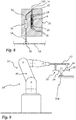
- Fig. 8 shows a schematic representation of the coating applicator used.
- Fig. 9 and 10 show a processing station and the coating process with the simultaneous use of two applicators.
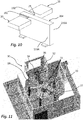
- Fig. 11 shows a coating system with a plurality of coating stations and further stations.
- FIG. 1 shows a motor vehicle battery 200.
- This comprises a plurality of battery cells 202, each of which has a prismatic housing.
- the battery cells 202 are flush with one another with outer surfaces 210A of their respective housings 204.
- the outer surfaces 210A, 210B, 210C of the housing 204 are each provided with an insulating layer made of a cured coating material.
- This coating can either be done after the assembly of the battery cell and thus in the state of the Fig. 2 respectively. Alternatively, however, the coating can also take place before assembly, so that at this point in time the housing 204 is in the Fig. 3 is still empty.
- the housing 204 to be coated is usually made of aluminum or an aluminum alloy.
- the coating is carried out with a coating applicator which is designed for the targeted delivery of individual drops.
- the Figures 4 and 5 illustrate this procedure.
- the method provides that the battery cell 202 or at least its housing 204 is fixed by means of a workpiece holder 70 and holding elements 72 provided for gripping the pole elements 206.
- a coating applicator 20, which will be explained in more detail below, is then positioned in the immediate vicinity of the surface to be coated, in the case of the arrangement of the Fig. 4 that is, immediately in front of the outer surface 210A.
- the nozzle opening 24 (not shown) of the coating applicator 20 and the surface to be coated is preferably a few millimeters, in the present case about 5 mm.
- the discharge then takes place in that the coating applicator generates discrete individual droplets of less than 1 mm 3 volume at a high frequency, which are emitted in a defined direction towards the outer surface 210A and a coating point 104 of about 1 when they hit the surface up to 2 mm in diameter.
- the total volume of the coating material remains on the surface. If the operating parameters of the coating applicator are suitably selected, there is no spray mist.
- the coating applicator 20 is displaced with respect to the outer surface 210A, as illustrated by arrow 2 and explained in more detail below. During this movement, further discrete individual drops 102 continue to be released in the direction of the surface, the frequency, the drop size and the speed of the coating applicator 20 being coordinated with one another in such a way that the coating points 104 overlap and thus form a continuous coating line 106.
- a contiguous coating surface 108 is formed by further coating lines 106, which are applied in an overlapping manner with previous coating lines 106.
- FIG. 6 shows the housing 204 after the coating is complete.
- the quality of the coating in terms of uniformity of the layer thickness is highest if the discharge takes place on a horizontal surface, as is the case here with the outer surface 210C, it has been shown that also on vertically aligned surfaces, such as the outer surfaces in the present case 210A, 210B, a high quality can be achieved. However, this also depends on the arrangement of the tracks 3, 5 along which the coating applicator 20 is moved relative to the housing 204. In principle, it is advantageous if the individual coating lines are aligned parallel to the longest extension of the respective surface to be coated. In the case of the outer surface 210A, the coating lines are therefore aligned horizontally, while in the case of the outer surface 210B they are aligned vertically. In particular when applying horizontal coating lines 106 on vertically aligned surfaces, in this case the outer surfaces 210A, it has proven to be advantageous if the coating lines are placed one below the other from top to bottom, as illustrated by the web 3.
- Fig. 7 shows the structure of a coating station, a robot 38 with a robot arm 40 being used in the present case to guide the coating applicator 20 provided at the distal end of the robot arm 40.
- the coating applicator 20 is supplied with liquid coating material from a storage store 50 in which the coating material 100 is stored prior to discharge. Since the coating materials particularly suitable for the method according to the invention usually have a very high viscosity at 20 ° C., the storage tank 50 is provided with a heating device 54 in order to keep the coating material at a higher temperature, in particular at a temperature between 35 ° C. and 45 ° C. As an alternative or in addition, heating devices can also be provided in the channels leading to the coating applicator or in the coating applicator 20 itself. Since the coating materials particularly suitable for the invention also tend to sedimentation, that is to say to the deposition of constituents when the liquid coating material is at rest, the storage tank has 50 also has an agitator, by means of which the coating material 100 is permanently homogenized.
- the storage reservoir 50 is provided with an annular channel 56 which has a supply channel section 56A and a return channel section 56B.
- the coating material 100 from the storage tank is sucked into the supply channel section 56A by means of a pump 62 during the coating process, but also during short breaks in the coating process, for example when changing the workpiece.
- the pump 62 causes a delivery pressure of approximately 4 bar downstream.
- a three-way valve 60 is provided, by means of which it is controlled whether the coating material is conveyed through the return channel section 56B back into the storage reservoir 50 or through a supply channel 58 in the direction of the coating applicator 20.
- the uninterrupted conveyance of coating material 100 from the supply store 50 serves the purpose in particular of ensuring a constant quality of the coating material.
- the coating material 100 circulating in the circuit of the storage reservoir 50 and the ring channel 56 is subjected to shear stress in the ring channel 56, as a result of which its viscosity drops.
- the coating material 100 remains motionless when the coating applicator is deactivated. Depending on the type of coating material, this is usually not critical for a few minutes. However, if the coating material 100 remains too long in the supply channel 58, an increase in viscosity and / or sedimentation occurs, so that the coating material should no longer be used for the coating.
- the system therefore has a flushing device, which comprises a flushing pump 66, which can convey cleaning liquid from a flushing agent tank 64 into the supply channel 58 in order to remove the coating material remaining therein through the coating applicator 20 or a separate outflow opening from the supply channel 58, so that then fresh material can be fed from the annular channel 56 to the supply channel 58.
- a flushing device which comprises a flushing pump 66, which can convey cleaning liquid from a flushing agent tank 64 into the supply channel 58 in order to remove the coating material remaining therein through the coating applicator 20 or a separate outflow opening from the supply channel 58, so that then fresh material can be fed from the annular channel 56 to the supply channel 58.
- a plurality of coating applicators are used in a preferred configuration of the coating method which will be explained below. In such a case, it is considered preferable if these are connected to a common ring channel 56.
- Fig. 8 shows a schematic and sectioned representation of a coating applicator 20. It can be seen that the end 59 of the supply channel 58 runs within the coating applicator 20, a further heating device 30 being provided here to ensure a particularly uniform temperature during the subsequent discharge of the coating material , especially between 35 ° C and 45 ° C.
- the supply channel 58 opens into a nozzle chamber 22, to which a nozzle opening 24 is connected.
- the discharge of the coating material in the form of discrete individual droplets 102 is brought about by a plunger 26 which can be moved back and forth in the direction of arrow 6 by piezo stacks 28.
- the ram is usually operated at a frequency between 100 Hz and 1000 Hz.
- coating material 100 flows in from the supply channel 58, which is pressed outwards through the nozzle opening during the subsequent movement of the plunger 26 in the direction of the nozzle chamber 22 and forms a discrete single drop.
- the speed of the plunger is comparatively low during retracting movements, since otherwise there is a risk that ambient air is sucked through the nozzle opening 24 into the nozzle chamber 22, which disturbs the droplet formation during the subsequent discharge and / or leads to air inclusions in the single drop 102 and subsequently in the coating point 104. In principle, this can be counteracted by increasing the pressure in the supply channel 58. If, however, a pressure is used here which is clearly above 4 bar, there is a risk that the individual drop 102 will be torn during discharge. It is therefore preferred that the speed during the retracting movement is lower than during the rapid movement of the plunger 26, preferably lower by at least a factor of 2.
- the Figures 9 and 10 show a supplemented variant of the procedure.
- This is characterized in that a plurality of coating applicators 20, preferably exactly two coating applicators, are guided together, in the present case by a common robot arm 40.
- the two coating applicators 20 are attached to a common carrier 42 and with their Nozzle openings 24 aligned facing one another, so that they can coat two opposite sides of the housing 204 simultaneously. This enables shorter cycle times to be achieved.
- Fig. 10 the two coating applicators 20 can be seen during the simultaneous coating in operation. Because they are attached to the common carrier 42, they are moved together during the coating process, so that they simultaneously apply the respective coating points 104 and coating lines 106 to the outer surfaces 210A of the housing 204.
- Fig. 11 shows a coating system 90 which can be used in the industrial large-scale production of electric vehicles and by means of which housings 204 of battery cells 202 are coated in a multi-stage process.
- the coating system 90 has a central rotary table 98 which can be rotated about the vertical axis and has a total of five workpiece holders 70. Arranged around this rotary table 98 are two coating stations 10, essentially that of the Fig. 7 or 9 correspond. Furthermore, a drying station 300 and a measuring station 310 for measuring the layer thickness achieved are provided here.
- the rotatable rotary table 98 is part of a conveyor system 92 which also has a transport robot 96, which removes battery cells 202 or housing 204 from a conveyor line 94 and positions them on one of the workpiece holders 70 of the rotary table 98.
- the transport robot 96 can additionally be designed to determine its exact position after positioning the battery cell 202 or the housing 204 on the workpiece holder 70, so that the coating stations 10 in particular adapt their path parameters depending on the exact position of the battery cell 202 or the housing 204 can.
- a separate device can also be provided between the transport robot and the first coating station 10 for this purpose.
- precise position determination can also be dispensed with.
- the housing 204 positioned by the transport robot 96 on the workpiece holder 70 and fixed there by the holding elements 72 is moved to the first coating station by rotating the rotary table 98 clockwise and, after coating there, on to the second coating station.
- the two coating stations successively apply coatings to various outer surfaces 210A, 210B, 210C in the manner described.
- the number of coating stations can be adjusted depending on the type of housing.
- the drying station 300 has a height-adjustable protective hood, on the inside of which corresponding UV light sources, in particular UV LEDs, are provided.
- the housing 204 has been delivered, this is lowered by means of the rotary table 98 so that it surrounds the housing 204.
- the protective hood is raised again.
- the layer thickness achieved is then checked at the measuring station 310.
- This also has a hood for this purpose, on the inside of which at least one measuring device is provided for measuring the layer thickness, with a plurality of measuring devices for detecting the layer thickness at different measuring points preferably being provided.
- the measurement is preferably carried out inductively.
- the housing is moved back into the area of the transport robot 96 by means of the rotary table 98.
- the holding elements 72 of the workpiece holder 70 are released and the housing 204 or the battery cell 202 transported back to the conveyor line 94, while at the same time another housing 204 or another battery cell is removed from the conveyor line 94 and fed to the rotary table 98 for coating.
Landscapes
- Chemical & Material Sciences (AREA)
- Chemical Kinetics & Catalysis (AREA)
- Electrochemistry (AREA)
- General Chemical & Material Sciences (AREA)
- Engineering & Computer Science (AREA)
- Inorganic Chemistry (AREA)
- Robotics (AREA)
- Physics & Mathematics (AREA)
- Plasma & Fusion (AREA)
- Application Of Or Painting With Fluid Materials (AREA)
- Coating Apparatus (AREA)
Priority Applications (5)
| Application Number | Priority Date | Filing Date | Title |
|---|---|---|---|
| EP19156664.5A EP3696875B1 (fr) | 2019-02-12 | 2019-02-12 | Procédé d'application d'une couche d'isolation sur un élément de batterie d'un véhicule et une station de revêtement ainsi qu'installation de revêtement destinée à la mise en uvre dudit procédé |
| US17/430,101 US20220143645A1 (en) | 2019-02-12 | 2020-01-16 | Method for applying an insulation layer to a motor vehicle battery cell |
| KR1020217028892A KR20210134342A (ko) | 2019-02-12 | 2020-01-16 | 자동차 배터리 셀에 절연층을 도포하는 방법 |
| CN202080014015.7A CN113383455A (zh) | 2019-02-12 | 2020-01-16 | 用于在机动车电池单体上涂覆绝缘层的方法和涂层站以及用于执行该方法的涂层设备 |
| PCT/EP2020/051052 WO2020164848A1 (fr) | 2019-02-12 | 2020-01-16 | Procédé pour appliquer une couche d'isolation sur un élément de batterie de véhicule automobile |
Applications Claiming Priority (1)
| Application Number | Priority Date | Filing Date | Title |
|---|---|---|---|
| EP19156664.5A EP3696875B1 (fr) | 2019-02-12 | 2019-02-12 | Procédé d'application d'une couche d'isolation sur un élément de batterie d'un véhicule et une station de revêtement ainsi qu'installation de revêtement destinée à la mise en uvre dudit procédé |
Publications (2)
| Publication Number | Publication Date |
|---|---|
| EP3696875A1 true EP3696875A1 (fr) | 2020-08-19 |
| EP3696875B1 EP3696875B1 (fr) | 2020-12-23 |
Family
ID=65411817
Family Applications (1)
| Application Number | Title | Priority Date | Filing Date |
|---|---|---|---|
| EP19156664.5A Active EP3696875B1 (fr) | 2019-02-12 | 2019-02-12 | Procédé d'application d'une couche d'isolation sur un élément de batterie d'un véhicule et une station de revêtement ainsi qu'installation de revêtement destinée à la mise en uvre dudit procédé |
Country Status (5)
| Country | Link |
|---|---|
| US (1) | US20220143645A1 (fr) |
| EP (1) | EP3696875B1 (fr) |
| KR (1) | KR20210134342A (fr) |
| CN (1) | CN113383455A (fr) |
| WO (1) | WO2020164848A1 (fr) |
Cited By (3)
| Publication number | Priority date | Publication date | Assignee | Title |
|---|---|---|---|---|
| CN115555222A (zh) * | 2022-10-27 | 2023-01-03 | 欣旺达电动汽车电池有限公司 | 一种喷涂方法、装置及仿形绝缘涂层 |
| CN116532318A (zh) * | 2023-07-04 | 2023-08-04 | 江苏常丰精密科技有限公司 | 一种动力电池壳体底部堵孔机构 |
| EP4258429A1 (fr) * | 2022-04-05 | 2023-10-11 | Volvo Car Corporation | Unité de fixation destinée à maintenir une cellule de batterie prismatique |
Families Citing this family (1)
| Publication number | Priority date | Publication date | Assignee | Title |
|---|---|---|---|---|
| USD965474S1 (en) * | 2020-10-26 | 2022-10-04 | Hyundai Motor Company | Automobile |
Citations (6)
| Publication number | Priority date | Publication date | Assignee | Title |
|---|---|---|---|---|
| EP0837514A1 (fr) * | 1996-10-18 | 1998-04-22 | VARTA Batterie Aktiengesellschaft | Element galvanique directement imprimé |
| JP2010194399A (ja) * | 2009-02-23 | 2010-09-09 | Fuji Xerox Co Ltd | 液滴吐出ヘッド及び液滴吐出装置 |
| DE102013206283A1 (de) * | 2013-04-10 | 2014-10-16 | Elringklinger Ag | Verfahren zum Applizieren von Beschichtungsmaterial und Appliziervorrichtung |
| DE102015205481A1 (de) | 2015-03-26 | 2016-09-29 | Bayerische Motoren Werke Aktiengesellschaft | Verbesserte Akkumulatoranordnung für ein elektrisch angetriebenes Fahrzeug |
| US20160329534A1 (en) * | 2014-01-14 | 2016-11-10 | Zpower, Llc | Polymer coatings for metal surfaces |
| WO2018082989A1 (fr) | 2016-11-04 | 2018-05-11 | Fredy Doll Beteiligungs-GmbH | Module de batterie de véhicule à moteur, véhicule à moteur doté d'un moteur d'entraînement électrique et d'un module de batterie et procédé de réalisation d'un module de batterie de véhicule à moteur et d'un véhicule à moteur |
Family Cites Families (5)
| Publication number | Priority date | Publication date | Assignee | Title |
|---|---|---|---|---|
| US5750207A (en) * | 1995-02-17 | 1998-05-12 | Si Diamond Technology, Inc. | System and method for depositing coating of modulated composition |
| DE102011088739A1 (de) * | 2011-12-15 | 2013-06-20 | Robert Bosch Gmbh | Gehäuse für eine Batteriezelle mit einer Lackbeschichtung zur elektrischen Isolation, Batteriezelle, Batterie sowie Kraftfahrzeug |
| US9502737B2 (en) * | 2013-05-23 | 2016-11-22 | Ambri Inc. | Voltage-enhanced energy storage devices |
| EP3063825A4 (fr) * | 2013-11-01 | 2017-06-28 | Ambri Inc. | Gestion thermique de batteries à métal liquide |
| DE102017210744A1 (de) * | 2017-06-27 | 2018-12-27 | Bayerische Motoren Werke Aktiengesellschaft | Elektrochemische Batteriezelle für ein Batteriemodul und Verfahren zur Herstellung einer Batteriezelle sowie Batteriemodul |
-
2019
- 2019-02-12 EP EP19156664.5A patent/EP3696875B1/fr active Active
-
2020
- 2020-01-16 WO PCT/EP2020/051052 patent/WO2020164848A1/fr active Application Filing
- 2020-01-16 KR KR1020217028892A patent/KR20210134342A/ko not_active Application Discontinuation
- 2020-01-16 US US17/430,101 patent/US20220143645A1/en active Pending
- 2020-01-16 CN CN202080014015.7A patent/CN113383455A/zh active Pending
Patent Citations (6)
| Publication number | Priority date | Publication date | Assignee | Title |
|---|---|---|---|---|
| EP0837514A1 (fr) * | 1996-10-18 | 1998-04-22 | VARTA Batterie Aktiengesellschaft | Element galvanique directement imprimé |
| JP2010194399A (ja) * | 2009-02-23 | 2010-09-09 | Fuji Xerox Co Ltd | 液滴吐出ヘッド及び液滴吐出装置 |
| DE102013206283A1 (de) * | 2013-04-10 | 2014-10-16 | Elringklinger Ag | Verfahren zum Applizieren von Beschichtungsmaterial und Appliziervorrichtung |
| US20160329534A1 (en) * | 2014-01-14 | 2016-11-10 | Zpower, Llc | Polymer coatings for metal surfaces |
| DE102015205481A1 (de) | 2015-03-26 | 2016-09-29 | Bayerische Motoren Werke Aktiengesellschaft | Verbesserte Akkumulatoranordnung für ein elektrisch angetriebenes Fahrzeug |
| WO2018082989A1 (fr) | 2016-11-04 | 2018-05-11 | Fredy Doll Beteiligungs-GmbH | Module de batterie de véhicule à moteur, véhicule à moteur doté d'un moteur d'entraînement électrique et d'un module de batterie et procédé de réalisation d'un module de batterie de véhicule à moteur et d'un véhicule à moteur |
Non-Patent Citations (1)
| Title |
|---|
| BRIAN DERBY ED - BRIAN DERBY: "Inkjet Printing of Functional and Structural Materials: Fluid property Requirements, feature Stability, and Resolution", ANNU. REV. MATER. RES,, vol. 40, 9 March 2010 (2010-03-09), pages 395 - 414, XP002788902, DOI: 10.1146/ANNUREV-MATSCI-070909-104502 * |
Cited By (5)
| Publication number | Priority date | Publication date | Assignee | Title |
|---|---|---|---|---|
| EP4258429A1 (fr) * | 2022-04-05 | 2023-10-11 | Volvo Car Corporation | Unité de fixation destinée à maintenir une cellule de batterie prismatique |
| EP4258435A3 (fr) * | 2022-04-05 | 2024-01-24 | Volvo Car Corporation | Unité de fixation destinée à maintenir une cellule de batterie prismatique |
| CN115555222A (zh) * | 2022-10-27 | 2023-01-03 | 欣旺达电动汽车电池有限公司 | 一种喷涂方法、装置及仿形绝缘涂层 |
| CN116532318A (zh) * | 2023-07-04 | 2023-08-04 | 江苏常丰精密科技有限公司 | 一种动力电池壳体底部堵孔机构 |
| CN116532318B (zh) * | 2023-07-04 | 2023-08-29 | 江苏常丰精密科技有限公司 | 一种动力电池壳体底部堵孔机构 |
Also Published As
| Publication number | Publication date |
|---|---|
| US20220143645A1 (en) | 2022-05-12 |
| WO2020164848A1 (fr) | 2020-08-20 |
| CN113383455A (zh) | 2021-09-10 |
| KR20210134342A (ko) | 2021-11-09 |
| EP3696875B1 (fr) | 2020-12-23 |
Similar Documents
| Publication | Publication Date | Title |
|---|---|---|
| EP3696875B1 (fr) | Procédé d'application d'une couche d'isolation sur un élément de batterie d'un véhicule et une station de revêtement ainsi qu'installation de revêtement destinée à la mise en uvre dudit procédé | |
| EP3698881B1 (fr) | Procédé de revêtement et dispositif de revêtement correspondant | |
| EP2566627B1 (fr) | Dispositif de revêtement présentant des jets de produit de revêtement divisés en forme de gouttes | |
| EP2337688A1 (fr) | Dispositif de revêtement, et procédé de revêtement correspondant | |
| EP3088090B1 (fr) | Dispositif de laquage et procédé de laquage d'une surface extérieure d'un objet laqué | |
| DE102012017538A1 (de) | Verfahren zum Bebildern und/oder Lackieren der Oberfläche von Gegenständen | |
| DE102008061203A1 (de) | Verfahren zum Lackieren einer dreidimensionalen Oberfläche eines Bauteils | |
| DE102013205171A1 (de) | Spritzsystem, Spritzvorrichtung, Schnellwechseladapter und Wechselvorrichtung, Beschichtungsanlage sowie Verfahren zum Beschichten | |
| EP0919015B1 (fr) | Procede et dispositif pour l'application de photoresist sur des surfaces de substrat non planes | |
| EP3576884B1 (fr) | Dispsitif d'application pour le revêtement de piéces et dispositif de revêtement | |
| DE102018131380A1 (de) | Reinigungsgerät für ein Applikationsgerät | |
| DE102018006397A1 (de) | Verfahren zum Herstellen eines dreidimensionalen Formgegenstands mittels schichtweisem Materialauftrag | |
| DE102010010053B4 (de) | Zerstäuber und Verfahren zum Applizieren von Ein- und Mehr-Komponenten-Beschichtungsmitteln | |
| DE202019005563U1 (de) | Beschichtungsstation sowie Beschichtungsanlage zur Durchführung eines Verfahrens zur Aufbringung einer Isolationsschicht auf einer Kfz-Batteriezelle | |
| DE102010038332A1 (de) | Beschichtungsvorrichtung und ein Beschichtungsverfahren | |
| DE102018008808A1 (de) | Verfahren zum Herstellen eines dreidimensionalen Formgegenstands mittels schichtweisem Materialauftrag | |
| WO2013087186A1 (fr) | Installation de revêtement et procédé d'utilisation correspondant | |
| DE102017205741A1 (de) | Beschichtungseinrichtung, Verfahren zum Herstellen eines beschichteten Bauteils und Kraftfahrzeug | |
| DE102012006048A1 (de) | Vorrichtung und Verfahren zum Aufbringen eines aus wenigstens zwei Komponenten bestehenden, reaktiven Gemisches auf ein Trägermaterial | |
| DE102016013317B4 (de) | Verfahren zum Herstellen eines dreidimensionalen Formgegenstands und Vorrichtung zur Durchführung des Verfahrens | |
| DE102018006091A1 (de) | Kontinuierlicher 3D-Pulver-Sinterdruck | |
| DE102005008741B4 (de) | Verfahren und Vorrichtung zum selektiven Befüllen von regelmässig angeordneten wabenartigen Strukturen | |
| EP1889666B1 (fr) | Dispositif destiné à recouvrir, en particulier pur laquer, des objets, en particulier de véhicules automobiles | |
| DE102017119341B4 (de) | Verfahren und Vorrichtung zur Behandlung von Pressblechen in der Leiterplattenlamination | |
| DE102011051737A1 (de) | Verfahren und Vorrichtung zum partiellen Abtragen einer Beschichtung |
Legal Events
| Date | Code | Title | Description |
|---|---|---|---|
| REG | Reference to a national code |
Ref country code: DE Ref legal event code: R138 Ref document number: 202019005563 Country of ref document: DE Free format text: GERMAN DOCUMENT NUMBER IS 502019000556 |
|
| STAA | Information on the status of an ep patent application or granted ep patent |
Free format text: STATUS: EXAMINATION IS IN PROGRESS |
|
| PUAI | Public reference made under article 153(3) epc to a published international application that has entered the european phase |
Free format text: ORIGINAL CODE: 0009012 |
|
| 17P | Request for examination filed |
Effective date: 20191115 |
|
| AK | Designated contracting states |
Kind code of ref document: A1 Designated state(s): AL AT BE BG CH CY CZ DE DK EE ES FI FR GB GR HR HU IE IS IT LI LT LU LV MC MK MT NL NO PL PT RO RS SE SI SK SM TR |
|
| AX | Request for extension of the european patent |
Extension state: BA ME |
|
| REG | Reference to a national code |
Ref country code: DE Ref legal event code: R079 Ref document number: 502019000556 Country of ref document: DE Free format text: PREVIOUS MAIN CLASS: H01M0002100000 Ipc: H01M0002020000 |
|
| GRAP | Despatch of communication of intention to grant a patent |
Free format text: ORIGINAL CODE: EPIDOSNIGR1 |
|
| STAA | Information on the status of an ep patent application or granted ep patent |
Free format text: STATUS: GRANT OF PATENT IS INTENDED |
|
| RIC1 | Information provided on ipc code assigned before grant |
Ipc: B05B 13/04 20060101ALI20200930BHEP Ipc: H01M 2/02 20060101AFI20200930BHEP Ipc: B05D 3/06 20060101ALI20200930BHEP Ipc: B05B 9/04 20060101ALI20200930BHEP Ipc: B05B 15/555 20180101ALI20200930BHEP Ipc: B05B 12/16 20180101ALI20200930BHEP Ipc: B05C 11/10 20060101ALI20200930BHEP Ipc: B05D 1/26 20060101ALI20200930BHEP Ipc: B05B 13/02 20060101ALI20200930BHEP Ipc: H01M 2/10 20060101ALI20200930BHEP Ipc: B05B 1/08 20060101ALI20200930BHEP Ipc: B05C 5/02 20060101ALI20200930BHEP Ipc: B05C 9/04 20060101ALI20200930BHEP Ipc: B05B 9/00 20060101ALI20200930BHEP Ipc: B05B 1/30 20060101ALI20200930BHEP Ipc: B05C 15/00 20060101ALI20200930BHEP |
|
| INTG | Intention to grant announced |
Effective date: 20201016 |
|
| RIC1 | Information provided on ipc code assigned before grant |
Ipc: B05B 1/08 20060101ALI20201005BHEP Ipc: B05B 15/555 20180101ALI20201005BHEP Ipc: B05B 1/30 20060101ALI20201005BHEP Ipc: B05B 9/04 20060101ALI20201005BHEP Ipc: B05D 3/06 20060101ALN20201005BHEP Ipc: B05C 5/02 20060101ALI20201005BHEP Ipc: B05C 11/10 20060101ALN20201005BHEP Ipc: B05B 9/00 20060101ALI20201005BHEP Ipc: H01M 2/02 20060101AFI20201005BHEP Ipc: B05D 1/26 20060101ALI20201005BHEP Ipc: B05C 15/00 20060101ALN20201005BHEP Ipc: H01M 2/10 20060101ALI20201005BHEP Ipc: B05C 9/04 20060101ALI20201005BHEP |
|
| GRAS | Grant fee paid |
Free format text: ORIGINAL CODE: EPIDOSNIGR3 |
|
| GRAA | (expected) grant |
Free format text: ORIGINAL CODE: 0009210 |
|
| STAA | Information on the status of an ep patent application or granted ep patent |
Free format text: STATUS: THE PATENT HAS BEEN GRANTED |
|
| AK | Designated contracting states |
Kind code of ref document: B1 Designated state(s): AL AT BE BG CH CY CZ DE DK EE ES FI FR GB GR HR HU IE IS IT LI LT LU LV MC MK MT NL NO PL PT RO RS SE SI SK SM TR |
|
| REG | Reference to a national code |
Ref country code: GB Ref legal event code: FG4D Free format text: NOT ENGLISH |
|
| REG | Reference to a national code |
Ref country code: DE Ref legal event code: R096 Ref document number: 502019000556 Country of ref document: DE |
|
| REG | Reference to a national code |
Ref country code: AT Ref legal event code: REF Ref document number: 1348582 Country of ref document: AT Kind code of ref document: T Effective date: 20210115 |
|
| REG | Reference to a national code |
Ref country code: IE Ref legal event code: FG4D Free format text: LANGUAGE OF EP DOCUMENT: GERMAN |
|
| PG25 | Lapsed in a contracting state [announced via postgrant information from national office to epo] |
Ref country code: GR Free format text: LAPSE BECAUSE OF FAILURE TO SUBMIT A TRANSLATION OF THE DESCRIPTION OR TO PAY THE FEE WITHIN THE PRESCRIBED TIME-LIMIT Effective date: 20210324 Ref country code: NO Free format text: LAPSE BECAUSE OF FAILURE TO SUBMIT A TRANSLATION OF THE DESCRIPTION OR TO PAY THE FEE WITHIN THE PRESCRIBED TIME-LIMIT Effective date: 20210323 Ref country code: FI Free format text: LAPSE BECAUSE OF FAILURE TO SUBMIT A TRANSLATION OF THE DESCRIPTION OR TO PAY THE FEE WITHIN THE PRESCRIBED TIME-LIMIT Effective date: 20201223 Ref country code: RS Free format text: LAPSE BECAUSE OF FAILURE TO SUBMIT A TRANSLATION OF THE DESCRIPTION OR TO PAY THE FEE WITHIN THE PRESCRIBED TIME-LIMIT Effective date: 20201223 |
|
| REG | Reference to a national code |
Ref country code: NL Ref legal event code: MP Effective date: 20201223 |
|
| PG25 | Lapsed in a contracting state [announced via postgrant information from national office to epo] |
Ref country code: BG Free format text: LAPSE BECAUSE OF FAILURE TO SUBMIT A TRANSLATION OF THE DESCRIPTION OR TO PAY THE FEE WITHIN THE PRESCRIBED TIME-LIMIT Effective date: 20210323 Ref country code: SE Free format text: LAPSE BECAUSE OF FAILURE TO SUBMIT A TRANSLATION OF THE DESCRIPTION OR TO PAY THE FEE WITHIN THE PRESCRIBED TIME-LIMIT Effective date: 20201223 Ref country code: LV Free format text: LAPSE BECAUSE OF FAILURE TO SUBMIT A TRANSLATION OF THE DESCRIPTION OR TO PAY THE FEE WITHIN THE PRESCRIBED TIME-LIMIT Effective date: 20201223 |
|
| PG25 | Lapsed in a contracting state [announced via postgrant information from national office to epo] |
Ref country code: HR Free format text: LAPSE BECAUSE OF FAILURE TO SUBMIT A TRANSLATION OF THE DESCRIPTION OR TO PAY THE FEE WITHIN THE PRESCRIBED TIME-LIMIT Effective date: 20201223 Ref country code: NL Free format text: LAPSE BECAUSE OF FAILURE TO SUBMIT A TRANSLATION OF THE DESCRIPTION OR TO PAY THE FEE WITHIN THE PRESCRIBED TIME-LIMIT Effective date: 20201223 |
|
| REG | Reference to a national code |
Ref country code: LT Ref legal event code: MG9D |
|
| PG25 | Lapsed in a contracting state [announced via postgrant information from national office to epo] |
Ref country code: CZ Free format text: LAPSE BECAUSE OF FAILURE TO SUBMIT A TRANSLATION OF THE DESCRIPTION OR TO PAY THE FEE WITHIN THE PRESCRIBED TIME-LIMIT Effective date: 20201223 Ref country code: SK Free format text: LAPSE BECAUSE OF FAILURE TO SUBMIT A TRANSLATION OF THE DESCRIPTION OR TO PAY THE FEE WITHIN THE PRESCRIBED TIME-LIMIT Effective date: 20201223 Ref country code: SM Free format text: LAPSE BECAUSE OF FAILURE TO SUBMIT A TRANSLATION OF THE DESCRIPTION OR TO PAY THE FEE WITHIN THE PRESCRIBED TIME-LIMIT Effective date: 20201223 Ref country code: EE Free format text: LAPSE BECAUSE OF FAILURE TO SUBMIT A TRANSLATION OF THE DESCRIPTION OR TO PAY THE FEE WITHIN THE PRESCRIBED TIME-LIMIT Effective date: 20201223 Ref country code: LT Free format text: LAPSE BECAUSE OF FAILURE TO SUBMIT A TRANSLATION OF THE DESCRIPTION OR TO PAY THE FEE WITHIN THE PRESCRIBED TIME-LIMIT Effective date: 20201223 Ref country code: RO Free format text: LAPSE BECAUSE OF FAILURE TO SUBMIT A TRANSLATION OF THE DESCRIPTION OR TO PAY THE FEE WITHIN THE PRESCRIBED TIME-LIMIT Effective date: 20201223 Ref country code: PT Free format text: LAPSE BECAUSE OF FAILURE TO SUBMIT A TRANSLATION OF THE DESCRIPTION OR TO PAY THE FEE WITHIN THE PRESCRIBED TIME-LIMIT Effective date: 20210423 |
|
| PG25 | Lapsed in a contracting state [announced via postgrant information from national office to epo] |
Ref country code: PL Free format text: LAPSE BECAUSE OF FAILURE TO SUBMIT A TRANSLATION OF THE DESCRIPTION OR TO PAY THE FEE WITHIN THE PRESCRIBED TIME-LIMIT Effective date: 20201223 |
|
| REG | Reference to a national code |
Ref country code: DE Ref legal event code: R097 Ref document number: 502019000556 Country of ref document: DE |
|
| PG25 | Lapsed in a contracting state [announced via postgrant information from national office to epo] |
Ref country code: MC Free format text: LAPSE BECAUSE OF FAILURE TO SUBMIT A TRANSLATION OF THE DESCRIPTION OR TO PAY THE FEE WITHIN THE PRESCRIBED TIME-LIMIT Effective date: 20201223 Ref country code: IS Free format text: LAPSE BECAUSE OF FAILURE TO SUBMIT A TRANSLATION OF THE DESCRIPTION OR TO PAY THE FEE WITHIN THE PRESCRIBED TIME-LIMIT Effective date: 20210423 |
|
| REG | Reference to a national code |
Ref country code: BE Ref legal event code: MM Effective date: 20210228 |
|
| PG25 | Lapsed in a contracting state [announced via postgrant information from national office to epo] |
Ref country code: LU Free format text: LAPSE BECAUSE OF NON-PAYMENT OF DUE FEES Effective date: 20210212 Ref country code: IT Free format text: LAPSE BECAUSE OF FAILURE TO SUBMIT A TRANSLATION OF THE DESCRIPTION OR TO PAY THE FEE WITHIN THE PRESCRIBED TIME-LIMIT Effective date: 20201223 Ref country code: AL Free format text: LAPSE BECAUSE OF FAILURE TO SUBMIT A TRANSLATION OF THE DESCRIPTION OR TO PAY THE FEE WITHIN THE PRESCRIBED TIME-LIMIT Effective date: 20201223 |
|
| PLBE | No opposition filed within time limit |
Free format text: ORIGINAL CODE: 0009261 |
|
| STAA | Information on the status of an ep patent application or granted ep patent |
Free format text: STATUS: NO OPPOSITION FILED WITHIN TIME LIMIT |
|
| PG25 | Lapsed in a contracting state [announced via postgrant information from national office to epo] |
Ref country code: DK Free format text: LAPSE BECAUSE OF FAILURE TO SUBMIT A TRANSLATION OF THE DESCRIPTION OR TO PAY THE FEE WITHIN THE PRESCRIBED TIME-LIMIT Effective date: 20201223 |
|
| 26N | No opposition filed |
Effective date: 20210924 |
|
| PG25 | Lapsed in a contracting state [announced via postgrant information from national office to epo] |
Ref country code: IE Free format text: LAPSE BECAUSE OF NON-PAYMENT OF DUE FEES Effective date: 20210212 Ref country code: ES Free format text: LAPSE BECAUSE OF FAILURE TO SUBMIT A TRANSLATION OF THE DESCRIPTION OR TO PAY THE FEE WITHIN THE PRESCRIBED TIME-LIMIT Effective date: 20201223 |
|
| REG | Reference to a national code |
Ref country code: DE Ref legal event code: R082 Ref document number: 502019000556 Country of ref document: DE Representative=s name: WITTE, WELLER & PARTNER PATENTANWAELTE MBB, DE |
|
| PG25 | Lapsed in a contracting state [announced via postgrant information from national office to epo] |
Ref country code: IS Free format text: LAPSE BECAUSE OF FAILURE TO SUBMIT A TRANSLATION OF THE DESCRIPTION OR TO PAY THE FEE WITHIN THE PRESCRIBED TIME-LIMIT Effective date: 20210423 |
|
| PG25 | Lapsed in a contracting state [announced via postgrant information from national office to epo] |
Ref country code: BE Free format text: LAPSE BECAUSE OF NON-PAYMENT OF DUE FEES Effective date: 20210228 |
|
| REG | Reference to a national code |
Ref country code: CH Ref legal event code: PL |
|
| PG25 | Lapsed in a contracting state [announced via postgrant information from national office to epo] |
Ref country code: LI Free format text: LAPSE BECAUSE OF NON-PAYMENT OF DUE FEES Effective date: 20220228 Ref country code: CH Free format text: LAPSE BECAUSE OF NON-PAYMENT OF DUE FEES Effective date: 20220228 |
|
| PGFP | Annual fee paid to national office [announced via postgrant information from national office to epo] |
Ref country code: FR Payment date: 20230217 Year of fee payment: 5 |
|
| P01 | Opt-out of the competence of the unified patent court (upc) registered |
Effective date: 20230510 |
|
| PG25 | Lapsed in a contracting state [announced via postgrant information from national office to epo] |
Ref country code: CY Free format text: LAPSE BECAUSE OF FAILURE TO SUBMIT A TRANSLATION OF THE DESCRIPTION OR TO PAY THE FEE WITHIN THE PRESCRIBED TIME-LIMIT Effective date: 20201223 |
|
| PG25 | Lapsed in a contracting state [announced via postgrant information from national office to epo] |
Ref country code: SI Free format text: LAPSE BECAUSE OF FAILURE TO SUBMIT A TRANSLATION OF THE DESCRIPTION OR TO PAY THE FEE WITHIN THE PRESCRIBED TIME-LIMIT Effective date: 20201223 Ref country code: HU Free format text: LAPSE BECAUSE OF FAILURE TO SUBMIT A TRANSLATION OF THE DESCRIPTION OR TO PAY THE FEE WITHIN THE PRESCRIBED TIME-LIMIT; INVALID AB INITIO Effective date: 20190212 |
|
| GBPC | Gb: european patent ceased through non-payment of renewal fee |
Effective date: 20230212 |
|
| PG25 | Lapsed in a contracting state [announced via postgrant information from national office to epo] |
Ref country code: GB Free format text: LAPSE BECAUSE OF NON-PAYMENT OF DUE FEES Effective date: 20230212 |
|
| PG25 | Lapsed in a contracting state [announced via postgrant information from national office to epo] |
Ref country code: GB Free format text: LAPSE BECAUSE OF NON-PAYMENT OF DUE FEES Effective date: 20230212 |
|
| PG25 | Lapsed in a contracting state [announced via postgrant information from national office to epo] |
Ref country code: MK Free format text: LAPSE BECAUSE OF FAILURE TO SUBMIT A TRANSLATION OF THE DESCRIPTION OR TO PAY THE FEE WITHIN THE PRESCRIBED TIME-LIMIT Effective date: 20201223 |
|
| PGFP | Annual fee paid to national office [announced via postgrant information from national office to epo] |
Ref country code: DE Payment date: 20240221 Year of fee payment: 6 |