EP3696614A1 - Fixing device and image forming apparatus incorporating same - Google Patents
Fixing device and image forming apparatus incorporating same Download PDFInfo
- Publication number
- EP3696614A1 EP3696614A1 EP20150103.8A EP20150103A EP3696614A1 EP 3696614 A1 EP3696614 A1 EP 3696614A1 EP 20150103 A EP20150103 A EP 20150103A EP 3696614 A1 EP3696614 A1 EP 3696614A1
- Authority
- EP
- European Patent Office
- Prior art keywords
- fixing
- fixing device
- nip plate
- longitudinal direction
- heat
- Prior art date
- Legal status (The legal status is an assumption and is not a legal conclusion. Google has not performed a legal analysis and makes no representation as to the accuracy of the status listed.)
- Granted
Links
Images







Classifications
-
- G—PHYSICS
- G03—PHOTOGRAPHY; CINEMATOGRAPHY; ANALOGOUS TECHNIQUES USING WAVES OTHER THAN OPTICAL WAVES; ELECTROGRAPHY; HOLOGRAPHY
- G03G—ELECTROGRAPHY; ELECTROPHOTOGRAPHY; MAGNETOGRAPHY
- G03G15/00—Apparatus for electrographic processes using a charge pattern
- G03G15/20—Apparatus for electrographic processes using a charge pattern for fixing, e.g. by using heat
- G03G15/2003—Apparatus for electrographic processes using a charge pattern for fixing, e.g. by using heat using heat
- G03G15/2014—Apparatus for electrographic processes using a charge pattern for fixing, e.g. by using heat using heat using contact heat
- G03G15/2039—Apparatus for electrographic processes using a charge pattern for fixing, e.g. by using heat using heat using contact heat with means for controlling the fixing temperature
- G03G15/2042—Apparatus for electrographic processes using a charge pattern for fixing, e.g. by using heat using heat using contact heat with means for controlling the fixing temperature specially for the axial heat partition
-
- G—PHYSICS
- G03—PHOTOGRAPHY; CINEMATOGRAPHY; ANALOGOUS TECHNIQUES USING WAVES OTHER THAN OPTICAL WAVES; ELECTROGRAPHY; HOLOGRAPHY
- G03G—ELECTROGRAPHY; ELECTROPHOTOGRAPHY; MAGNETOGRAPHY
- G03G15/00—Apparatus for electrographic processes using a charge pattern
- G03G15/20—Apparatus for electrographic processes using a charge pattern for fixing, e.g. by using heat
- G03G15/2003—Apparatus for electrographic processes using a charge pattern for fixing, e.g. by using heat using heat
- G03G15/2014—Apparatus for electrographic processes using a charge pattern for fixing, e.g. by using heat using heat using contact heat
- G03G15/2053—Structural details of heat elements, e.g. structure of roller or belt, eddy current, induction heating
-
- G—PHYSICS
- G03—PHOTOGRAPHY; CINEMATOGRAPHY; ANALOGOUS TECHNIQUES USING WAVES OTHER THAN OPTICAL WAVES; ELECTROGRAPHY; HOLOGRAPHY
- G03G—ELECTROGRAPHY; ELECTROPHOTOGRAPHY; MAGNETOGRAPHY
- G03G2215/00—Apparatus for electrophotographic processes
- G03G2215/20—Details of the fixing device or porcess
- G03G2215/2003—Structural features of the fixing device
- G03G2215/2016—Heating belt
- G03G2215/2035—Heating belt the fixing nip having a stationary belt support member opposing a pressure member
Definitions
- Embodiments of the present disclosure generally relate to a fixing device and an image forming apparatus incorporating the fixing device.
- Electrophotographic image forming apparatuses use various types of fixing devices.
- a halogen heater heats a thin fixing belt having a low thermal capacity.
- JP-2013-114057-A discloses such a fixing device.
- This type of fixing device includes a fixing belt, a nip plate inside a loop of the fixing belt, and a pressure roller outside the fixing belt, and the fixing belt is sandwiched between the nip plate and the pressure roller.
- the halogen heater heats the nip plate, and the nip plate heats the fixing belt.
- the nip plate is supported by a stay having a channel-shaped cross section.
- the sheet conveyance area of the fixing belt When the image forming apparatus starts printing, the sheet conveyance area of the fixing belt must be sufficiently heated to a temperature necessary for fixing. When a job interval is long, the image forming apparatus enters a sleep mode. Since the heater does not work in the sleep mode, the temperature of the sheet conveyance area decreases. When printing starts immediately after the image forming apparatus returns from the sleep mode, the temperature of the sheet conveyance area often rises from a low temperature.
- Raising the temperature of the sheet conveyance area of the fixing belt from the low temperature takes some time.
- raising the temperature at end portions of the sheet conveyance area takes much time because heat escapes to a non-sheet conveyance area.
- a recovery time from the sleep mode is prolonged.
- the nip plate is extended upstream in the rotation direction of the fixing belt, and the halogen heater heats the extended portion of the nip plate with radiant heat to shorten the recovery time from the sleep mode.
- the side plate of the stay upstream in the rotation direction of the fixing belt is shortened in a vertical direction to support the extended portion of the nip plate.
- raising the temperature at end portions of the sheet conveyance area in a short time is difficult.
- An object of the present disclosure is raising the temperature at end portions of the sheet conveyance area in a short time without reducing the strength of the stay.
- the fixing device includes a rotatable endless fixing member, a heat generator disposed in a longitudinal direction of the fixing member inside a loop of the fixing member, a nip plate disposed in the longitudinal direction of the fixing member in slidable contact with an inner peripheral surface of the fixing member, a support disposed around the heat generator and configured to support the heat generator, a pressing member disposed opposite the nip plate to form a fixing nip between the fixing member and the pressing member, a heating portion, a reflector disposed inside the support and configured to reflect heat generated by the heat generator toward the nip plate, and an extended reflector.
- the heating portion is positioned at an upstream end in a sheet conveyance direction in the fixing nip and provided in at least one end portion of the nip plate in a longitudinal direction of the nip plate.
- the extended reflector extends upstream in the sheet conveyance direction to face the heating portion and is formed in at least one end portion of the reflector in a longitudinal direction of the reflector.
- the temperature at end portions of the sheet conveyance area can be raised in a short time without reducing the strength of the stay.
- the image forming apparatus can be a copier, a facsimile machine, a printer, a plotter, and a multifunction peripheral having at least two of copying, printing, facsimile transmission, plotting, and scanning capabilities; or an inkjet recording apparatus.
- a “recording medium” is described as a “sheet” in the following embodiment, the “recording medium” is not limited to the sheet.
- Examples of the “recording medium” include not only the sheet but also an overhead projector (OHP) transparency, a fabric, a metallic sheet, a plastic film, and a prepreg sheet including carbon fibers previously impregnated with resin.
- OHP overhead projector
- Examples of the "recording medium” include all mediums to which developer or ink can adhere, and so-called recording paper and recording sheets.
- Examples of the "sheet” include thick paper, a postcard, an envelope, thin paper, coated paper (e.g., coat paper and art paper), and tracing paper, in addition to plain paper.
- image formation indicates an action for providing (i.e., printing) not only an image having a meaning, such as texts and figures on a recording medium, but also an image having no meaning, such as patterns on a recording medium.
- FIG. 1 is an explanatory diagram to describe the laser printer as the present embodiment of the image forming apparatus 100 including the fixing device 300 according to the embodiment of the present disclosure.
- the image forming apparatus 100 includes an image bearer 2 such as a photoconductor drum and a photoconductor cleaner 3.
- the image forming apparatus 100 further includes a charging device 4 as a charger that uniformly charges the surface of the image bearer, a developing device 5 as a developing unit that renders visible an electrostatic latent image on the image bearer, a transfer device TM disposed under the image bearer 2, a discharger, and the like.
- An exposure device 7 is disposed above the image bearer 2.
- the exposure device 7 performs writing and scanning based on image data, namely, irradiates the image bearer 2 with laser light Lb emitted by a laser diode based on image data and reflected by a mirror 7a.
- a sheet feeder 50 including a tray loaded with sheets P is disposed below the image forming apparatus 100.
- the sheet feeder 50 is configured as a recording-medium supply device and can house a sheaf of many recording media sheets P.
- the sheet feeder 50 is configured as one unit together with a sheet feeding roller 60 as a conveyor for the sheets P.
- a registration roller pair 250 Downstream from the sheet feeding roller 60, a registration roller pair 250 as a separation and conveyance means is disposed.
- the registration roller pair 250 temporarily stops the sheet P fed from the sheet feeder 50. Temporarily stopping the sheet P causes slack on the leading-edge side of the sheet P and corrects a skew of the sheet P.
- the registration roller pair 250 sends the sheet P that contacts the registration roller pair 250 and has the slack on the leading-edge side of the sheet P toward a transfer nip of the transfer device TM at a timing to suitably transfer a toner image on the image bearer 2 onto the sheet P.
- a bias applied at the transfer nip N electrostatically transfers the toner image formed on the image bearer 2 onto the sent sheet P at a desired transfer position.
- the fixing device 300 is disposed downstream from the transfer nip N.
- the fixing device 300 includes a fixing belt 310 as a fixing member containing a halogen heater as a heat generator described below and a pressure roller 320 as a pressing member that rotates while pressing against the fixing belt 310 with a predetermined pressure.
- the sheet feeding roller 60 rotates in response to a sheet feeding signal from a controller of the image forming apparatus 100.
- the sheet feeding roller 60 separates the uppermost sheet from a sheaf of sheets P loaded in the sheet feeder 50 and sends the uppermost sheet out to a sheet feeding path.
- the sheet feeding roller 60 sends the sheet P
- the sheet P forms slack and temporarily stops.
- the slack corrects skew of the sheet P.
- the registration roller pair 250 rotates in synchronization with an optimum timing to transfer a toner image on the image bearer 2 onto the sheet P.
- the charging device 4 uniformly charges the surface of the image bearer 2 to high potential.
- the exposure device 7 irradiates the surface of the image bearer 2 with the laser light Lb based on the image data and reflected by the mirror 7a.
- the surface of the image bearer 2 irradiated with the laser light Lb has an electrostatic latent image due to a drop in the potential of the irradiated portion.
- the developing device 5 includes a developer bearer bearing a developer including toner and transfers unused black toner supplied from the toner bottle to the surface portion of the image bearer 2 having the electrostatic latent image, through the developer bearer.
- the image bearer 2 to which the toner has been transferred forms (develops) a black toner image on the surface of the image bearer 2.
- the transfer device TM transfers the toner image formed on the image bearer 2 onto the sheet P.
- a cleaning blade 3a in the photoconductor cleaner 3 removes the residual toner adhering to the surface of the image bearer 2 after a transfer process.
- the removed residual toner is collected to a waste toner container.
- the sheet P bearing the toner image is conveyed to the fixing device 300.
- the sheet P conveyed to the fixing device 300 is sandwiched by the fixing belt 310 and the pressure roller 320. Then, heating and pressing fixes the unfixed toner image onto the sheet P.
- the sheet P fixed the toner image is sent out from the fixing device 300.
- the fixing device 300 includes a thin fixing belt 310 having low thermal capacity and a pressure roller 320.
- the fixing belt 310 includes, for example, a tubular base made of polyimide (PI), the tubular base having an outer diameter of 25 mm and a thickness of from 40 to 120 ⁇ m.
- PI polyimide
- the fixing belt 310 further includes a release layer serving as an outermost surface layer.
- the release layer is made of fluororesin, such as tetrafluoroethylene-perfluoroalkylvinylether copolymer (PFA) and polytetrafluoroethylene (PTFE), and has a thickness of from 5 ⁇ m to 50 ⁇ m to enhance durability of the fixing belt 310 and facilitate separation of the sheet P from the fixing belt 310.
- An elastic layer made of rubber having a thickness of from 50 to 500 ⁇ m may be provided between the base and the release layer.
- the tubular base of the fixing belt 310 is not limited to polyimide, and thus may be made of heat-resistant resin, such as polyetheretherketone (PEEK), or a metal, such as nickel (Ni) or stainless steel (SUS).
- PEEK polyetheretherketone
- Ni nickel
- SUS stainless steel
- the inner circumferential surface of the fixing belt 310 may be coated with polyimide or polytetrafluoroethylene (PTFE) as a slide layer.
- the pressure roller 320 having, for example, an outer diameter of 25 mm, includes a solid iron cored bar 321, an elastic layer 322 on the surface of the cored bar 321, and a release layer 323 formed on the outside of the elastic layer 322.
- the elastic layer 322 is made of silicone rubber and has, for example, a thickness of 3.5 mm.
- the release layer 323 is formed by a fluororesin layer having, for example, a thickness of approximately 40 ⁇ m on the surface of the elastic layer 322 to improve releasability.
- a biasing member presses the pressure roller 320 against the fixing belt 310.
- a stay 330 and a nip plate 380 as a first heating portion are arranged axially inside the fixing belt 310.
- the stay 330 is configured by a channeled metallic member having a U-shaped cross section, and both side plates of the fixing device 300 support both end portions of the stay 330.
- the stay 330 reliably receives the pressing force of the pressure roller 320 to form the fixing nip SN stably.
- the nip plate 380 transfers heat in an axial direction that is the width direction of the fixing belt 310 to uniformize temperature of the fixing belt 310 in the width direction.
- the nip plate 380 is made of a member having high thermal conductivity such as copper, aluminum or silver to smoothly transfer the heat in the width direction. In consideration of cost, processing, and the like, the nip plate 380 is preferably made of copper.
- Both ends of the nip plate 380 in a short-side direction are supported by the downward opening ends of the stay 330.
- extension parts 380a as a second heating portion positioned at an upstream end of the fixing nip in a sheet conveyance direction.
- the extension parts 380a extend in a predetermined length along the inner peripheral surface of the fixing belt 310 and has a substantially arc shape toward the upstream side in the rotation direction.
- the extension parts 380a are formed at least at both end portions in the longitudinal direction of the nip plate 380 to raise temperature at both end portions of the fixing belt 310 as described below.
- the extension parts 380a guides the fixing belt 310 entering the fixing nip SN and preheats the fixing belt 310.
- the "longitudinal direction" of the nip plate 380 is the same direction as the axial direction of halogen heaters 361 and 362.
- the extension part 380a may be formed over the entire length of the nip plate 380 in the longitudinal direction of the nip plate 380.
- the central portion (intermediate portion) of the nip plate 380 in the longitudinal direction corresponds to the sheet conveyance area, and heat is difficult to escape. Therefore, since the temperature necessary for fixing can be easily secured in the central portion of the nip plate 380, forming the extension parts 380a at both end portions of the nip plate 380 in the longitudinal direction as illustrated in FIG. 4B is sufficient to maintain the temperature necessary for fixing.
- both end portions in the longitudinal direction mean portions outside the maximum sheet conveyance area.
- the nip plate 380 is bent substantially perpendicularly upward along the outside surface of a downstream side wall 330a of the stay 330 to form a lubricant regulating part 380b.
- the lubricant regulating part 380b prevents lubricant adhering to the inner peripheral surface of the fixing belt 310 from entering the upper surface, painted in black, of the nip plate 380.
- the lubricant regulating part 380b can prevent the heating efficiency from decreasing.
- the stay 330 is a channel member having a U-shaped cross section that opens downward.
- the downward opening ends of the stay 330 support the nip plate 380.
- the pressure roller 320 presses the nip plate 380 via the fixing belt 310 to form the fixing nip SN between the nip plate 380 and the fixing belt 310.
- the stay 330 has a downstream side wall 330a, a ceiling wall 330b, and an upstream side wall 330c.
- the ceiling wall 330b connects the upper end of the downstream side wall 330a and the upper end of the upstream side wall 330c.
- the nip plate 380 is fixed to the lower end of the downstream side wall 330a and the lower end of the upstream side wall 330c. Therefore, the stay 330 forms a closed space, that is, the space in which the upper, lower, left and right sides are closed, inside the stay 330.
- Halogen heaters 361 and 362 are arranged axially in the closed space inside the stay 330. Both side plates of the fixing device 300 support both ends of the halogen heaters 361 and 362.
- One halogen heater 361 has a heat generation portion h1 in a center part in the axial direction as illustrated in FIG. 3 , and radiant heat from the heat generation portion h1 heats the center part of the fixing belt 310 in the width direction.
- the other halogen heater 362 as a second heat generator is disposed adjacent to the upstream side of the one halogen heater 361.
- the halogen heater 362 has a heat generation portion h2 in both end parts in the axial direction as illustrated in FIG. 3 , and radiant heat from the heat generation portion h2 heats both end parts of the fixing belt 310 in the width direction.
- halogen heater 361 When a small size sheet P such as a postcard or a A4 size sheet whose shorter side is set parallel to the width direction of the fixing belt passes through the fixing device, only the halogen heater 361 generates heat. When a large size sheet P such as a A3 size sheet passes through the fixing device, both the halogen heater 361 and the halogen heater 362 generate heat. Widths of heating areas of the halogen heaters 361 and 362 are arranged based on a width L of the A3 size sheet.
- the reflector 370 is disposed inside the stay 330.
- the cross-section of the reflector 370 is a part of ellipse.
- the heat generation portion h1 of the halogen heater 361 is positioned at the focal position of the ellipse.
- the reflector 370 is configured so that the reflector 370 reflects the radiant heat emitted by the heat generation portion h1 of the halogen heater 361 to the side and upward toward the upper face of the nip plate 380.
- the stay 330 has inclined portions 330d inclined toward the upstream side in the rotation direction of the fixing belt 310 as illustrated in FIG. 4A .
- the width of the inclined portion 330d in the longitudinal direction may be set to the same as the width of the extension part 380a described above in the longitudinal direction.
- a cutting part 330e divides the stay 330 into the inclined portions 330d at both end portions in the longitudinal direction and the upstream side wall 330c at the center portion in the longitudinal direction.
- the ratio of the width of the upstream side wall 330c to the overall length of the stay 330 in the longitudinal direction is quite large. Therefore, the strength of the stay 330 against the pressure applied by the pressure roller 320 can be sufficiently ensured, and the fixing device 300 can be easily reduced in size.
- the cutting part 330e may be closed with a wall to prevent heat escape.
- the reflector 370 has extended reflectors 370b at both end portions in the longitudinal direction.
- a cutting part 370c divides the reflector 370 into the extended reflectors 370b at both end portions in the longitudinal direction and a central reflector 370a at the center portion in the longitudinal direction.
- the cutting part 370c may also be closed with a wall to prevent heat escape.
- the extended reflector 370b is formed to have the same width as the inclined portion 330d of the stay 330 described above and extends along the inner surface of the inclined portion 330d.
- the tip of the extended reflector 370b may be fixed to the tip of the inclined portion 330d as necessary.
- the extended reflector 370b expands a radiation region of the nip plate 380 which the halogen heater 362 irradiates with the radiant heat. That is, the heat generation portions h2 at both end portions of the halogen heater 362 in the axial direction directly irradiate the upper surface of the nip plate 380 with the radiant heat. Additionally, the extended reflector 370b reflects the radiant heat emitted from the heat generation portion h2 to the upper side and the upstream side in the rotation direction of the fixing belt 310 toward the extension part 380a to irradiate the extension part 380a with the radiant heat.
- FIGS. 2A to 2D when the sheet P is conveyed in a direction indicated by a horizontal arrow and passes through the fixing nip SN, the sheet P is heated between the fixing belt 310 and the pressure roller 320 so that the toner image is fixed to the sheet P. At this time, the radiant heat from the halogen heaters 361 and 362 heats the fixing belt 310 through the nip plate 380.
- FIGS. 2A and 2B are slightly different in the arrangement of the halogen heater 362.
- the temperature of the fixing belt at an end portion corresponding to one of two ends of the sheet having the sheet width L tends to be low, which results in a long recovery time from a sleep mode to avoid fixing failure caused by the low temperature.
- the halogen heater 362 heats the extension parts 380a provided at both ends of the nip plate 380.
- the extension parts 380a preheat the fixing belt 310 before entering the fixing nip SN.
- This preliminary heating gives an effect of raising the temperature of the fixing belt at both end portions as illustrated by the upward arrow in FIG. 3 and shortens the recovery time from the sleep mode, that is, the time required to reach the temperature necessary for fixing in the sheet conveyance area.
- the halogen heater 361 described above has the heat generation portion h1 in the center part in the axial direction as illustrated in FIG. 3 , but the halogen heater 363 may be used as the first heat generator that has the heat generation portion h3 wholly generating heat in the axial direction as illustrated in FIG. 6 .
- Such a configuration enables a watt density at both end portions of the halogen heater 362 and 363 facing the extension parts 380a to be greater than a watt density at a center portion of the halogen heaters 362 and 363.
- the watt density is a heater power per unit surface area, that is, a value of a heater power [W] divided by a heater surface area [cm 2 ].
- Increasing winding density of the heater increases the watt density. Setting the watt density at both end portions of the halogen heater 362 and 363 in the longitudinal direction to be greater than the watt density at the center portion of the halogen heaters 362 and 363 can ensure the effect of raising the temperature of the fixing belt at both end portions, accelerate a speed of rising the temperature of the fixing belt at both end portions, and shorten the recovery time from the sleep mode.
- the fixing device 300 may use only one halogen heater 363 that has the heat generation portion h3 wholly generating heat in the axial direction. That is, as described above, preheating both end portions of the fixing belt 310 by the extension parts 380a can give an effect of raising the temperature of the fixing belt at both end portions, which prevents the temperature of the fixing belt at both end portions from lowering, and shorten the recovery time from the sleep mode even when only one halogen heater 363 is used.
- first variation to fifth variation are described in which the fixing device 300 uses different types of halogen heaters, or the halogen heaters are arranged at different positions.
- the fixing device 300 uses the one halogen heater 363 as the first heat generator having the heat generation portion h3 wholly generating heat in the axial direction.
- the extension part 380a as the second heating portion is disposed at both end portion in the longitudinal direction of the nip plate 380 as the first heating portion and extends upstream in the rotation direction of the fixing belt 310. Facing the extension part 380a, both end portions of the reflector 370 in the longitudinal direction opens toward upstream in the rotation direction of the fixing belt 310 to form the extended reflectors 370b.
- the above-described configuration enables the halogen heater 363 to heat both end portions of the fixing belt 310 from upstream in the rotation direction of the fixing belt 310 and accelerate the speed of rising the temperature of the fixing belt at both end portions.
- the fixing device 300 includes, in addition to the halogen heater 363 in FIGS. 8A and 8B , an end heater to heat the end portions, that is, the halogen heater 362 as the second heater.
- the halogen heater 362 to heat the end portions has the heat generation portion h2 in both end parts in the axial direction and is disposed adjacent to the immediately upstream side of the halogen heater 361 to heat an entire width of the fixing belt 310.
- the added halogen heater 362 to heat the end portions can effectively heat the extension parts 380a as the second heating portion of the nip plate 380 and further accelerate the temperature increase at the end portions of the fixing belt 310.
- the fixing device 300 according to the second variation illustrated in FIGS. 8C and 8D includes the halogen heater 363 to heat the entire width of the fixing belt 310 and the halogen heater 362 to heat the end portions of the fixing belt 310
- the fixing device 300 according to the third variation illustrated in FIGS. 8E and 8F uses the halogen heater 361 having the heat generation portion h1 in the center part in the axial direction instead of the halogen heater 363 to heat the entire width of the fixing belt 310.
- the fixing device 300 according to the third variation has a configuration having two heaters, that is, the halogen heater 361 to heat the center portion of the fixing belt 310 and the halogen heater 362 to heat the end portion of the fixing belt 310.
- the extension part 380a as the second heating portion of the nip plate 380 also extends upstream in the rotation direction of the fixing belt 310, and, facing the extension part 380a, both end portions of the reflector 370 in the longitudinal direction opens toward upstream in the rotation direction of the fixing belt 310 to form the extended reflectors 370b.
- the above-described configuration enables the halogen heater 362 to heat both end portions of the fixing belt 310 from upstream in the rotation direction of the fixing belt 310 and accelerate the speed of rising the temperature of the fixing belt at both end portions.
- the halogen heater 362 that is disposed in the fixing device 300 according to the second variation in FIGS. 8C and 8D to heat the end portions of the fixing belt 310 is disposed between a center of the reflector 370 in the sheet conveyance direction and the extended reflectors 370b.
- the halogen heater 362 that is disposed upstream in the sheet conveyance direction as described above and heats the end portions of the nip plate 380 can effectively heat the extension parts 380a as the second heating portion of the nip plate 380 and accelerate the temperature increase at the end portions of the fixing belt 310 because the halogen heater 362 heats both end portions of the fixing belt 310 from further upstream side.
- the fixing device 300 according to the fifth variation in FIGS. 8I and 8J uses the halogen heater 361 having the heat generation portion h1 in the center part of the halogen heater 361 in the axial direction instead of the halogen heater 363 used in the fourth variation in FIGS. 8G and 8H to heat the entire width of the fixing belt 310.
- the halogen heater 362 since the halogen heater 362 is disposed upstream in the sheet conveyance direction and heats the end portions of the nip plate 380, the halogen heater 362 can effectively heat the extension parts 380a as the second heating portion of the nip plate 380 and accelerate the temperature increase at the end portions of the fixing belt 310 because the halogen heater 362 heats both end portions of the fixing belt 310 from further upstream side.
- the inclined portion 330d of the stay 330 may be omitted. That is, as the sixth variation in FIG. 9A , cutout portions 330f are formed at both end portions of the upstream side wall 330c of the stay 330 in the longitudinal direction, and the extended reflectors 370b are projected outward under the cutout portions 330f as illustrated in FIG. 9B .
- the present disclosure has been described above on the basis of the embodiment and the variations, but the present disclosure is not limited to the embodiment and variations. Needless to say, various alterations can be made in the scope of the technical idea described in the scope of the claims.
- the described fixing device has one or two halogen heaters 361 and 362 (or 362 and 363), but, of course, three or more halogen heaters may be used.
Landscapes
- Physics & Mathematics (AREA)
- General Physics & Mathematics (AREA)
- Fixing For Electrophotography (AREA)
Abstract
Description
- Embodiments of the present disclosure generally relate to a fixing device and an image forming apparatus incorporating the fixing device.
- Electrophotographic image forming apparatuses use various types of fixing devices. In one type of fixing devices, a halogen heater heats a thin fixing belt having a low thermal capacity. For example,
JP-2013-114057-A - When the image forming apparatus starts printing, the sheet conveyance area of the fixing belt must be sufficiently heated to a temperature necessary for fixing. When a job interval is long, the image forming apparatus enters a sleep mode. Since the heater does not work in the sleep mode, the temperature of the sheet conveyance area decreases. When printing starts immediately after the image forming apparatus returns from the sleep mode, the temperature of the sheet conveyance area often rises from a low temperature.
- Raising the temperature of the sheet conveyance area of the fixing belt from the low temperature takes some time. In particular, raising the temperature at end portions of the sheet conveyance area takes much time because heat escapes to a non-sheet conveyance area. As a result, a recovery time from the sleep mode is prolonged. In the fixing device disclosed in
JP-2013-114057-A - However, in the fixing device disclosed in
JP-2013-114057-A - An object of the present disclosure is raising the temperature at end portions of the sheet conveyance area in a short time without reducing the strength of the stay.
- It is a general object of the present disclosure to provide an improved and useful fixing device in which the above-mentioned problems are eliminated. In order to achieve the above-mentioned object, there is provided a fixing device according to claim 1. Advantageous embodiments are defined by the dependent claims.
- Advantageously, the fixing device includes a rotatable endless fixing member, a heat generator disposed in a longitudinal direction of the fixing member inside a loop of the fixing member, a nip plate disposed in the longitudinal direction of the fixing member in slidable contact with an inner peripheral surface of the fixing member, a support disposed around the heat generator and configured to support the heat generator, a pressing member disposed opposite the nip plate to form a fixing nip between the fixing member and the pressing member, a heating portion, a reflector disposed inside the support and configured to reflect heat generated by the heat generator toward the nip plate, and an extended reflector. The heating portion is positioned at an upstream end in a sheet conveyance direction in the fixing nip and provided in at least one end portion of the nip plate in a longitudinal direction of the nip plate. The extended reflector extends upstream in the sheet conveyance direction to face the heating portion and is formed in at least one end portion of the reflector in a longitudinal direction of the reflector.
- According to the present disclosure, the temperature at end portions of the sheet conveyance area can be raised in a short time without reducing the strength of the stay.
- The aforementioned and other aspects, features, and advantages of the present disclosure would be better understood by reference to the following detailed description when considered in connection with the accompanying drawings, wherein:
-
FIG. 1 is an explanatory diagram to describe an image forming apparatus according to the embodiment of the present disclosure; -
FIG. 2A is a cross-sectional view of a center portion of a fixing device according to the embodiment of the present disclosure; -
FIG. 2B is a cross-sectional view of an end portion of the fixing device according to the embodiment of the present disclosure; -
FIG. 2C is a cross-sectional view of the center portion of the fixing device in which the arrangement of the halogen heater is different from that of the fixing device inFIG. 2A ; -
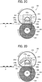
FIG. 2D is a cross-sectional view of the end portion of the fixing device in which the arrangement of the halogen heater is different from that of the fixing device inFIG. 2B ; -
FIG. 3 is an explanatory diagram illustrating temperature rising in the end portion of a fixing belt when two halogen heaters are used; -
FIG. 4A is a perspective view illustrating a stay of the fixing device; -
FIG. 4B is a perspective view illustrating a nip plate of the fixing device; -
FIG. 5 is a perspective view of a reflector of the fixing device; -
FIG. 6 is an explanatory diagram illustrating temperature rising in the end portion of the fixing belt when two halogen heaters that are different from the heaters inFIG. 3 are used; -
FIG. 7 is an explanatory diagram illustrating temperature rising in the end portion of the fixing belt when one halogen heater is used; -
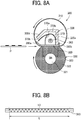
FIG. 8A is a cross-sectional view of the end portion of the fixing device according to a first variation; -
FIG. 8B is a schematic diagram illustrating the halogen heater of the fixing device according to the first variation; -
FIG. 8C is a cross-sectional view of the end portion of the fixing device according to a second variation; -
FIG. 8D is a schematic diagram illustrating the halogen heater of the fixing device according to the second variation; -
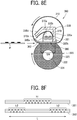
FIG. 8E is a cross-sectional view of the end portion of the fixing device according to a third variation; -
FIG. 8F is a schematic diagram illustrating the halogen heater of the fixing device according to the third variation; -
FIG. 8G is a cross-sectional view of the end portion of the fixing device according to a fourth variation; -
FIG. 8H is a schematic diagram illustrating the halogen heater of the fixing device according to the fourth variation; -
FIG. 8I is a cross-sectional view of the end portion of the fixing device according to a fifth variation; -
FIG. 8J is a schematic diagram illustrating the halogen heater of the fixing device according to the fifth variation; -
FIG. 9A is a perspective view illustrating a stay of the fixing device according to a sixth variation; and -
FIG. 9B is a cross-sectional view of the end portion of the fixing device according to the sixth variation. - The accompanying drawings are intended to depict embodiments of the present disclosure and should not be interpreted to limit the scope thereof. The accompanying drawings are not to be considered as drawn to scale unless explicitly noted.
- In describing embodiments illustrated in the drawings, specific terminology is employed for the sake of clarity. However, the disclosure of this specification is not intended to be limited to the specific terminology so selected and it is to be understood that each specific element includes all technical equivalents that have a similar function, operate in a similar manner, and achieve a similar result.
- Although the embodiments are described with technical limitations with reference to the attached drawings, such description is not intended to limit the scope of the disclosure and all of the components or elements described in the embodiments of this disclosure are not necessarily indispensable.
- Referring now to the drawings, embodiments of the present disclosure are described below. In the drawings illustrating the following embodiments, the same reference codes are allocated to elements (members or components) having the same function or shape and redundant descriptions thereof are omitted below.
- With reference to drawings, a description is given of a fixing device according to an embodiment of the present disclosure and an image forming apparatus such as a laser printer using the fixing device. The laser printer according to the present embodiment is just one embodiment, and thus the image forming apparatus is not limited to the laser printer. That is, the image forming apparatus can be a copier, a facsimile machine, a printer, a plotter, and a multifunction peripheral having at least two of copying, printing, facsimile transmission, plotting, and scanning capabilities; or an inkjet recording apparatus.
- It is to be understood that an identical or similar reference character is given to identical or corresponding parts throughout the drawings, and redundant descriptions are omitted or simplified below. The dimensions, material, shape, and relative position in a description for each constituent component are examples. Unless otherwise specifically described, the scope of the present disclosure is not limited to those.
- Although a "recording medium" is described as a "sheet" in the following embodiment, the "recording medium" is not limited to the sheet. Examples of the "recording medium" include not only the sheet but also an overhead projector (OHP) transparency, a fabric, a metallic sheet, a plastic film, and a prepreg sheet including carbon fibers previously impregnated with resin.
- Examples of the "recording medium" include all mediums to which developer or ink can adhere, and so-called recording paper and recording sheets. Examples of the "sheet" include thick paper, a postcard, an envelope, thin paper, coated paper (e.g., coat paper and art paper), and tracing paper, in addition to plain paper.
- The term "image formation" indicates an action for providing (i.e., printing) not only an image having a meaning, such as texts and figures on a recording medium, but also an image having no meaning, such as patterns on a recording medium.
- A configuration of the image forming apparatus according to the present embodiment is described below.
-
FIG. 1 is an explanatory diagram to describe the laser printer as the present embodiment of theimage forming apparatus 100 including thefixing device 300 according to the embodiment of the present disclosure. Theimage forming apparatus 100 includes animage bearer 2 such as a photoconductor drum and aphotoconductor cleaner 3. Theimage forming apparatus 100 further includes acharging device 4 as a charger that uniformly charges the surface of the image bearer, a developingdevice 5 as a developing unit that renders visible an electrostatic latent image on the image bearer, a transfer device TM disposed under theimage bearer 2, a discharger, and the like. - An
exposure device 7 is disposed above theimage bearer 2. Theexposure device 7 performs writing and scanning based on image data, namely, irradiates theimage bearer 2 with laser light Lb emitted by a laser diode based on image data and reflected by amirror 7a. - A
sheet feeder 50 including a tray loaded with sheets P is disposed below theimage forming apparatus 100. Thesheet feeder 50 is configured as a recording-medium supply device and can house a sheaf of many recording media sheets P. Thesheet feeder 50 is configured as one unit together with asheet feeding roller 60 as a conveyor for the sheets P. - Downstream from the
sheet feeding roller 60, aregistration roller pair 250 as a separation and conveyance means is disposed. Theregistration roller pair 250 temporarily stops the sheet P fed from thesheet feeder 50. Temporarily stopping the sheet P causes slack on the leading-edge side of the sheet P and corrects a skew of the sheet P. - The
registration roller pair 250 sends the sheet P that contacts theregistration roller pair 250 and has the slack on the leading-edge side of the sheet P toward a transfer nip of the transfer device TM at a timing to suitably transfer a toner image on theimage bearer 2 onto the sheet P. A bias applied at the transfer nip N electrostatically transfers the toner image formed on theimage bearer 2 onto the sent sheet P at a desired transfer position. - The fixing
device 300 is disposed downstream from the transfer nip N. The fixingdevice 300 includes a fixingbelt 310 as a fixing member containing a halogen heater as a heat generator described below and apressure roller 320 as a pressing member that rotates while pressing against the fixingbelt 310 with a predetermined pressure. - Next, operation of the
image forming apparatus 100 according to the present embodiment is described below. - The
sheet feeding roller 60 rotates in response to a sheet feeding signal from a controller of theimage forming apparatus 100. Thesheet feeding roller 60 separates the uppermost sheet from a sheaf of sheets P loaded in thesheet feeder 50 and sends the uppermost sheet out to a sheet feeding path. - After the
sheet feeding roller 60 sends the sheet P, when the leading edge of the sheet P reaches a nip of theregistration roller pair 250, the sheet P forms slack and temporarily stops. The slack corrects skew of the sheet P. Theregistration roller pair 250 rotates in synchronization with an optimum timing to transfer a toner image on theimage bearer 2 onto the sheet P. - The charging
device 4 uniformly charges the surface of theimage bearer 2 to high potential. Theexposure device 7 irradiates the surface of theimage bearer 2 with the laser light Lb based on the image data and reflected by themirror 7a. - The surface of the
image bearer 2 irradiated with the laser light Lb has an electrostatic latent image due to a drop in the potential of the irradiated portion. The developingdevice 5 includes a developer bearer bearing a developer including toner and transfers unused black toner supplied from the toner bottle to the surface portion of theimage bearer 2 having the electrostatic latent image, through the developer bearer. - The
image bearer 2 to which the toner has been transferred forms (develops) a black toner image on the surface of theimage bearer 2. The transfer device TM transfers the toner image formed on theimage bearer 2 onto the sheet P. - A
cleaning blade 3a in thephotoconductor cleaner 3 removes the residual toner adhering to the surface of theimage bearer 2 after a transfer process. The removed residual toner is collected to a waste toner container. - The sheet P bearing the toner image is conveyed to the
fixing device 300. The sheet P conveyed to thefixing device 300 is sandwiched by the fixingbelt 310 and thepressure roller 320. Then, heating and pressing fixes the unfixed toner image onto the sheet P. The sheet P fixed the toner image is sent out from the fixingdevice 300. - Next, a description is given of the fixing
device 300 according to the present embodiment of the present disclosure. - As illustrated in
FIGS. 2A to 2D , the fixingdevice 300 includes athin fixing belt 310 having low thermal capacity and apressure roller 320. The fixingbelt 310 includes, for example, a tubular base made of polyimide (PI), the tubular base having an outer diameter of 25 mm and a thickness of from 40 to 120 µm. - The fixing
belt 310 further includes a release layer serving as an outermost surface layer. The release layer is made of fluororesin, such as tetrafluoroethylene-perfluoroalkylvinylether copolymer (PFA) and polytetrafluoroethylene (PTFE), and has a thickness of from 5 µm to 50 µm to enhance durability of the fixingbelt 310 and facilitate separation of the sheet P from the fixingbelt 310. An elastic layer made of rubber having a thickness of from 50 to 500 µm may be provided between the base and the release layer. - The tubular base of the fixing
belt 310 is not limited to polyimide, and thus may be made of heat-resistant resin, such as polyetheretherketone (PEEK), or a metal, such as nickel (Ni) or stainless steel (SUS). The inner circumferential surface of the fixingbelt 310 may be coated with polyimide or polytetrafluoroethylene (PTFE) as a slide layer. - The
pressure roller 320 having, for example, an outer diameter of 25 mm, includes a solid iron coredbar 321, anelastic layer 322 on the surface of the coredbar 321, and arelease layer 323 formed on the outside of theelastic layer 322. Theelastic layer 322 is made of silicone rubber and has, for example, a thickness of 3.5 mm. - Preferably, the
release layer 323 is formed by a fluororesin layer having, for example, a thickness of approximately 40 µm on the surface of theelastic layer 322 to improve releasability. A biasing member presses thepressure roller 320 against the fixingbelt 310. - A
stay 330 and a nipplate 380 as a first heating portion are arranged axially inside the fixingbelt 310. Thestay 330 is configured by a channeled metallic member having a U-shaped cross section, and both side plates of the fixingdevice 300 support both end portions of thestay 330. Thestay 330 reliably receives the pressing force of thepressure roller 320 to form the fixing nip SN stably. - The nip
plate 380 transfers heat in an axial direction that is the width direction of the fixingbelt 310 to uniformize temperature of the fixingbelt 310 in the width direction. The nipplate 380 is made of a member having high thermal conductivity such as copper, aluminum or silver to smoothly transfer the heat in the width direction. In consideration of cost, processing, and the like, thenip plate 380 is preferably made of copper. - Both ends of the
nip plate 380 in a short-side direction are supported by the downward opening ends of thestay 330. As illustrated inFIG. 4B , at the upstream end of thenip plate 380 in the rotation direction of the fixingbelt 310, there areextension parts 380a as a second heating portion positioned at an upstream end of the fixing nip in a sheet conveyance direction. Theextension parts 380a extend in a predetermined length along the inner peripheral surface of the fixingbelt 310 and has a substantially arc shape toward the upstream side in the rotation direction. Theextension parts 380a are formed at least at both end portions in the longitudinal direction of thenip plate 380 to raise temperature at both end portions of the fixingbelt 310 as described below. Theextension parts 380a guides the fixingbelt 310 entering the fixing nip SN and preheats the fixingbelt 310. In the present embodiment, the "longitudinal direction" of thenip plate 380 is the same direction as the axial direction ofhalogen heaters - The
extension part 380a may be formed over the entire length of thenip plate 380 in the longitudinal direction of thenip plate 380. However, the central portion (intermediate portion) of thenip plate 380 in the longitudinal direction corresponds to the sheet conveyance area, and heat is difficult to escape. Therefore, since the temperature necessary for fixing can be easily secured in the central portion of thenip plate 380, forming theextension parts 380a at both end portions of thenip plate 380 in the longitudinal direction as illustrated inFIG. 4B is sufficient to maintain the temperature necessary for fixing. Here, both end portions in the longitudinal direction mean portions outside the maximum sheet conveyance area. - At the downstream end of the
nip plate 380 in the rotation direction of the fixingbelt 310, thenip plate 380 is bent substantially perpendicularly upward along the outside surface of adownstream side wall 330a of thestay 330 to form alubricant regulating part 380b. Thelubricant regulating part 380b prevents lubricant adhering to the inner peripheral surface of the fixingbelt 310 from entering the upper surface, painted in black, of thenip plate 380. - When the lubricant enters the upper surface of the
nip plate 380, the heating efficiency of thenip plate 380 decreases. Thelubricant regulating part 380b can prevent the heating efficiency from decreasing. - As illustrated in
FIGS. 2A to 2D , thestay 330 is a channel member having a U-shaped cross section that opens downward. The downward opening ends of thestay 330 support thenip plate 380. Thepressure roller 320 presses thenip plate 380 via the fixingbelt 310 to form the fixing nip SN between thenip plate 380 and the fixingbelt 310. - The
stay 330 has adownstream side wall 330a, aceiling wall 330b, and anupstream side wall 330c. Theceiling wall 330b connects the upper end of thedownstream side wall 330a and the upper end of theupstream side wall 330c. - The nip
plate 380 is fixed to the lower end of thedownstream side wall 330a and the lower end of theupstream side wall 330c. Therefore, thestay 330 forms a closed space, that is, the space in which the upper, lower, left and right sides are closed, inside thestay 330. - Next, halogen heaters in the present embodiment are described.
-
Halogen heaters stay 330. Both side plates of the fixingdevice 300 support both ends of thehalogen heaters - One
halogen heater 361 has a heat generation portion h1 in a center part in the axial direction as illustrated inFIG. 3 , and radiant heat from the heat generation portion h1 heats the center part of the fixingbelt 310 in the width direction. Theother halogen heater 362 as a second heat generator is disposed adjacent to the upstream side of the onehalogen heater 361. Thehalogen heater 362 has a heat generation portion h2 in both end parts in the axial direction as illustrated inFIG. 3 , and radiant heat from the heat generation portion h2 heats both end parts of the fixingbelt 310 in the width direction. - When a small size sheet P such as a postcard or a A4 size sheet whose shorter side is set parallel to the width direction of the fixing belt passes through the fixing device, only the
halogen heater 361 generates heat. When a large size sheet P such as a A3 size sheet passes through the fixing device, both thehalogen heater 361 and thehalogen heater 362 generate heat. Widths of heating areas of thehalogen heaters - Next, a reflector in the present embodiment is described.
- The
reflector 370 is disposed inside thestay 330. The cross-section of thereflector 370 is a part of ellipse. The heat generation portion h1 of thehalogen heater 361 is positioned at the focal position of the ellipse. Thereflector 370 is configured so that thereflector 370 reflects the radiant heat emitted by the heat generation portion h1 of thehalogen heater 361 to the side and upward toward the upper face of thenip plate 380. - Both end portions of the
stay 330 in the longitudinal direction of thestay 330 and both end portions of thereflector 370 in the longitudinal direction of thereflector 370 open toward the upstream side in the rotation direction of the fixingbelt 310 as illustrated inFIGS. 2B and2D . At the both end portions in the longitudinal direction, thestay 330 has inclinedportions 330d inclined toward the upstream side in the rotation direction of the fixingbelt 310 as illustrated inFIG. 4A . The width of theinclined portion 330d in the longitudinal direction may be set to the same as the width of theextension part 380a described above in the longitudinal direction. - A cutting
part 330e divides thestay 330 into theinclined portions 330d at both end portions in the longitudinal direction and theupstream side wall 330c at the center portion in the longitudinal direction. However, the ratio of the width of theupstream side wall 330c to the overall length of thestay 330 in the longitudinal direction is quite large. Therefore, the strength of thestay 330 against the pressure applied by thepressure roller 320 can be sufficiently ensured, and the fixingdevice 300 can be easily reduced in size. The cuttingpart 330e may be closed with a wall to prevent heat escape. - The
reflector 370 has extendedreflectors 370b at both end portions in the longitudinal direction. A cuttingpart 370c divides thereflector 370 into theextended reflectors 370b at both end portions in the longitudinal direction and acentral reflector 370a at the center portion in the longitudinal direction. The cuttingpart 370c may also be closed with a wall to prevent heat escape. - The
extended reflector 370b is formed to have the same width as theinclined portion 330d of thestay 330 described above and extends along the inner surface of theinclined portion 330d. The tip of theextended reflector 370b may be fixed to the tip of theinclined portion 330d as necessary. - The
extended reflector 370b expands a radiation region of thenip plate 380 which thehalogen heater 362 irradiates with the radiant heat. That is, the heat generation portions h2 at both end portions of thehalogen heater 362 in the axial direction directly irradiate the upper surface of thenip plate 380 with the radiant heat. Additionally, theextended reflector 370b reflects the radiant heat emitted from the heat generation portion h2 to the upper side and the upstream side in the rotation direction of the fixingbelt 310 toward theextension part 380a to irradiate theextension part 380a with the radiant heat. - Next, a fixing operation is described.
- In
FIGS. 2A to 2D , when the sheet P is conveyed in a direction indicated by a horizontal arrow and passes through the fixing nip SN, the sheet P is heated between the fixingbelt 310 and thepressure roller 320 so that the toner image is fixed to the sheet P. At this time, the radiant heat from thehalogen heaters belt 310 through thenip plate 380.FIGS. 2A and 2B are slightly different in the arrangement of thehalogen heater 362. - As illustrated by a broken line in
FIG. 3 , in conventional fixing devices, the temperature of the fixing belt at an end portion corresponding to one of two ends of the sheet having the sheet width L tends to be low, which results in a long recovery time from a sleep mode to avoid fixing failure caused by the low temperature. In the embodiment of the present disclosure, as described above, thehalogen heater 362 heats theextension parts 380a provided at both ends of thenip plate 380. - Accordingly, the
extension parts 380a preheat the fixingbelt 310 before entering the fixing nip SN. This preliminary heating gives an effect of raising the temperature of the fixing belt at both end portions as illustrated by the upward arrow inFIG. 3 and shortens the recovery time from the sleep mode, that is, the time required to reach the temperature necessary for fixing in the sheet conveyance area. - The
halogen heater 361 described above has the heat generation portion h1 in the center part in the axial direction as illustrated inFIG. 3 , but thehalogen heater 363 may be used as the first heat generator that has the heat generation portion h3 wholly generating heat in the axial direction as illustrated inFIG. 6 . Such a configuration enables a watt density at both end portions of thehalogen heater extension parts 380a to be greater than a watt density at a center portion of thehalogen heaters - The watt density is a heater power per unit surface area, that is, a value of a heater power [W] divided by a heater surface area [cm2]. Increasing winding density of the heater increases the watt density. Setting the watt density at both end portions of the
halogen heater halogen heaters - As illustrated in
FIG. 7 , the fixingdevice 300 may use only onehalogen heater 363 that has the heat generation portion h3 wholly generating heat in the axial direction. That is, as described above, preheating both end portions of the fixingbelt 310 by theextension parts 380a can give an effect of raising the temperature of the fixing belt at both end portions, which prevents the temperature of the fixing belt at both end portions from lowering, and shorten the recovery time from the sleep mode even when only onehalogen heater 363 is used. - With reference to
FIGS. 8A to 8J , from first variation to fifth variation are described in which thefixing device 300 uses different types of halogen heaters, or the halogen heaters are arranged at different positions. - With reference to
FIGS. 8A and 8B , the first variation is described. - The fixing
device 300 according to the first variation uses the onehalogen heater 363 as the first heat generator having the heat generation portion h3 wholly generating heat in the axial direction. Theextension part 380a as the second heating portion is disposed at both end portion in the longitudinal direction of thenip plate 380 as the first heating portion and extends upstream in the rotation direction of the fixingbelt 310. Facing theextension part 380a, both end portions of thereflector 370 in the longitudinal direction opens toward upstream in the rotation direction of the fixingbelt 310 to form theextended reflectors 370b. The above-described configuration enables thehalogen heater 363 to heat both end portions of the fixingbelt 310 from upstream in the rotation direction of the fixingbelt 310 and accelerate the speed of rising the temperature of the fixing belt at both end portions. - With reference to
FIGS. 8C and 8D , a second variation is described. - The fixing
device 300 according to the second variation includes, in addition to thehalogen heater 363 inFIGS. 8A and 8B , an end heater to heat the end portions, that is, thehalogen heater 362 as the second heater. Thehalogen heater 362 to heat the end portions has the heat generation portion h2 in both end parts in the axial direction and is disposed adjacent to the immediately upstream side of thehalogen heater 361 to heat an entire width of the fixingbelt 310. The addedhalogen heater 362 to heat the end portions can effectively heat theextension parts 380a as the second heating portion of thenip plate 380 and further accelerate the temperature increase at the end portions of the fixingbelt 310. - A third variation is described below.
- Although the
fixing device 300 according to the second variation illustrated inFIGS. 8C and 8D includes thehalogen heater 363 to heat the entire width of the fixingbelt 310 and thehalogen heater 362 to heat the end portions of the fixingbelt 310, the fixingdevice 300 according to the third variation illustrated inFIGS. 8E and 8F uses thehalogen heater 361 having the heat generation portion h1 in the center part in the axial direction instead of thehalogen heater 363 to heat the entire width of the fixingbelt 310. In other words, the fixingdevice 300 according to the third variation has a configuration having two heaters, that is, thehalogen heater 361 to heat the center portion of the fixingbelt 310 and thehalogen heater 362 to heat the end portion of the fixingbelt 310. - In this configuration, the
extension part 380a as the second heating portion of thenip plate 380 also extends upstream in the rotation direction of the fixingbelt 310, and, facing theextension part 380a, both end portions of thereflector 370 in the longitudinal direction opens toward upstream in the rotation direction of the fixingbelt 310 to form theextended reflectors 370b. The above-described configuration enables thehalogen heater 362 to heat both end portions of the fixingbelt 310 from upstream in the rotation direction of the fixingbelt 310 and accelerate the speed of rising the temperature of the fixing belt at both end portions. - Next, a fourth variation is described below.
- In the
fixing device 300 according to the fourth variation inFIGS. 8G and 8H , thehalogen heater 362 that is disposed in thefixing device 300 according to the second variation inFIGS. 8C and 8D to heat the end portions of the fixingbelt 310 is disposed between a center of thereflector 370 in the sheet conveyance direction and theextended reflectors 370b. Thehalogen heater 362 that is disposed upstream in the sheet conveyance direction as described above and heats the end portions of thenip plate 380 can effectively heat theextension parts 380a as the second heating portion of thenip plate 380 and accelerate the temperature increase at the end portions of the fixingbelt 310 because thehalogen heater 362 heats both end portions of the fixingbelt 310 from further upstream side. - Next, a fifth variation is described below.
- The fixing
device 300 according to the fifth variation inFIGS. 8I and 8J uses thehalogen heater 361 having the heat generation portion h1 in the center part of thehalogen heater 361 in the axial direction instead of thehalogen heater 363 used in the fourth variation inFIGS. 8G and 8H to heat the entire width of the fixingbelt 310. In such a configuration, since thehalogen heater 362 is disposed upstream in the sheet conveyance direction and heats the end portions of thenip plate 380, thehalogen heater 362 can effectively heat theextension parts 380a as the second heating portion of thenip plate 380 and accelerate the temperature increase at the end portions of the fixingbelt 310 because thehalogen heater 362 heats both end portions of the fixingbelt 310 from further upstream side. - Next, a sixth variation is described below.
- In the first to fifth variations described above, the
inclined portion 330d of thestay 330 may be omitted. That is, as the sixth variation inFIG. 9A ,cutout portions 330f are formed at both end portions of theupstream side wall 330c of thestay 330 in the longitudinal direction, and theextended reflectors 370b are projected outward under thecutout portions 330f as illustrated inFIG. 9B . - The present disclosure has been described above on the basis of the embodiment and the variations, but the present disclosure is not limited to the embodiment and variations. Needless to say, various alterations can be made in the scope of the technical idea described in the scope of the claims. For example, in the above-described embodiment and variations, the described fixing device has one or two
halogen heaters 361 and 362 (or 362 and 363), but, of course, three or more halogen heaters may be used. - Numerous additional modifications and variations are possible in light of the above teachings. It is therefore to be understood that, within the scope of the above teachings, the present disclosure may be practiced otherwise than as specifically described herein. With some embodiments having thus been described, it will be obvious that the same may be varied in many ways. Such variations are not to be regarded as a departure from the scope of the present disclosure and appended claims, and all such modifications are intended to be included within the scope of the present disclosure and appended claims.
Claims (6)
- A fixing device (300) comprising:a rotatable endless fixing member (310);a heat generator (361, 362) disposed in a longitudinal direction of the fixing member (310) inside a loop of the fixing member (310);a nip plate (380) disposed in the longitudinal direction of the fixing member (310) in slidable contact with an inner peripheral surface of the fixing member (310);a support (330) disposed around the heat generator (361, 362) and configured to support the heat generator (361, 362);a pressing member (320) disposed opposite the nip plate (380) to form a fixing nip between the fixing member (310) and the pressing member (320);a heating portion (380a) positioned at an upstream end in a sheet conveyance direction in the fixing nip and provided in at least one end portion of the nip plate (380) in a longitudinal direction of the nip plate (380);a reflector (370) disposed inside the support (330) and configured to reflect heat generated by the heat generator (361, 362) toward the nip plate (380); andan extended reflector (370b) extending upstream in the sheet conveyance direction to face the heating portion (380a), the extended reflector (370b) being disposed in at least one end portion of the reflector (370) in a longitudinal direction of the reflector (370).
- The fixing device (300) according to claim 1,
wherein the support (330) has an inclined portion (330d) that is a side wall of the support (330) upstream in the sheet conveyance direction,
wherein the inclined portion (330d) is inclined upstream in the sheet conveyance direction and disposed in at least one end portion of the side wall in a longitudinal direction of the support (330), and
wherein the extended reflector (370b) is disposed inside the inclined portion (330d). - The fixing device (300) according to claim 1,
wherein the support (330) has a cutout portion (330f) disposed in a side wall of the support (330) upstream in the sheet conveyance direction and disposed in at least one end portion of the side wall in a longitudinal direction of the support (330), and
wherein the extended reflector (370b) projects outward through the cutout portion (330f). - The fixing device (300) according to any one of claims 1 to 3, wherein a watt density of at least one end portion of the heat generator (361, 362) in a longitudinal direction of the heat generator (361, 362) facing the heating portion (380a) of the nip plate (380) is greater than a watt density of a center portion of the heat generator (361, 362) in the longitudinal direction of the heat generator (361, 362).
- The fixing device (300) according to claim 3, wherein the heat generator (361, 362) includes:a first heat generator (363) configured to wholly heat the nip plate (380) in a longitudinal direction of the nip plate (380); anda second heat generator (362) configured to heat the heating portion (380a).
- An image forming apparatus (100) comprising:a developing device (5) configured to form an image on a recording medium; andthe fixing device (300) according to any one of claims 1 to 5 configured to fix the image onto the recording medium.
Applications Claiming Priority (3)
| Application Number | Priority Date | Filing Date | Title |
|---|---|---|---|
| JP2019016345 | 2019-01-31 | ||
| JP2019063174 | 2019-03-28 | ||
| JP2019202169A JP7338412B2 (en) | 2019-01-31 | 2019-11-07 | Fixing device and image forming device |
Publications (2)
| Publication Number | Publication Date |
|---|---|
| EP3696614A1 true EP3696614A1 (en) | 2020-08-19 |
| EP3696614B1 EP3696614B1 (en) | 2022-08-10 |
Family
ID=69104325
Family Applications (1)
| Application Number | Title | Priority Date | Filing Date |
|---|---|---|---|
| EP20150103.8A Active EP3696614B1 (en) | 2019-01-31 | 2020-01-02 | Fixing device and image forming apparatus incorporating same |
Country Status (1)
| Country | Link |
|---|---|
| EP (1) | EP3696614B1 (en) |
Cited By (1)
| Publication number | Priority date | Publication date | Assignee | Title |
|---|---|---|---|---|
| EP4009111A1 (en) * | 2020-12-01 | 2022-06-08 | Ricoh Company, Ltd. | Fixing device and image forming apparatus |
Citations (4)
| Publication number | Priority date | Publication date | Assignee | Title |
|---|---|---|---|---|
| JP2013114057A (en) | 2011-11-29 | 2013-06-10 | Brother Ind Ltd | Fixing device |
| US20130279955A1 (en) * | 2012-03-27 | 2013-10-24 | Brother Kogyo Kabushiki Kaisha | Fixing Device |
| US20140294419A1 (en) * | 2013-03-28 | 2014-10-02 | Brother Kogyo Kabushiki Kaisha | Image Forming Apparatus and Heat Fixing Device Provided in the Same |
| US20170017182A1 (en) * | 2015-07-15 | 2017-01-19 | Kazuya Saito | Fixing device and image forming apparatus |
-
2020
- 2020-01-02 EP EP20150103.8A patent/EP3696614B1/en active Active
Patent Citations (4)
| Publication number | Priority date | Publication date | Assignee | Title |
|---|---|---|---|---|
| JP2013114057A (en) | 2011-11-29 | 2013-06-10 | Brother Ind Ltd | Fixing device |
| US20130279955A1 (en) * | 2012-03-27 | 2013-10-24 | Brother Kogyo Kabushiki Kaisha | Fixing Device |
| US20140294419A1 (en) * | 2013-03-28 | 2014-10-02 | Brother Kogyo Kabushiki Kaisha | Image Forming Apparatus and Heat Fixing Device Provided in the Same |
| US20170017182A1 (en) * | 2015-07-15 | 2017-01-19 | Kazuya Saito | Fixing device and image forming apparatus |
Cited By (2)
| Publication number | Priority date | Publication date | Assignee | Title |
|---|---|---|---|---|
| EP4009111A1 (en) * | 2020-12-01 | 2022-06-08 | Ricoh Company, Ltd. | Fixing device and image forming apparatus |
| US11662678B2 (en) | 2020-12-01 | 2023-05-30 | Ricoh Company, Ltd. | Fixing device with controlled heating and image forming apparatus |
Also Published As
| Publication number | Publication date |
|---|---|
| EP3696614B1 (en) | 2022-08-10 |
Similar Documents
| Publication | Publication Date | Title |
|---|---|---|
| US10678172B2 (en) | Heating device, fixing device, and image forming apparatus | |
| US9454114B2 (en) | Fixing device and image forming apparatus including same | |
| US9164445B2 (en) | Fixing device and image forming apparatus | |
| US20200379384A1 (en) | Heating device, fixing device, and image forming apparatus | |
| JP5375540B2 (en) | Fixing apparatus and image forming apparatus | |
| JP2014178607A (en) | Fixing device and image forming apparatus | |
| JP7338412B2 (en) | Fixing device and image forming device | |
| US9477191B2 (en) | Fixing device with back-up member and nip forming member including a projecting portion projecting toward the back-up member | |
| JPH103231A (en) | Roll fixing device of uniform nip speed | |
| US20200192259A1 (en) | Fixing apparatus | |
| US11442407B2 (en) | Cooling device, fixing device, and image forming apparatus | |
| EP3709095A1 (en) | Heating device, fixing device, and image forming apparatus | |
| US11703783B2 (en) | Fixing device and image forming apparatus | |
| EP3696614B1 (en) | Fixing device and image forming apparatus incorporating same | |
| US20190258196A1 (en) | Fixing device and image forming apparatus | |
| EP3757679B1 (en) | Heating device, fixing device, and image forming apparatus | |
| JP6032541B2 (en) | Fixing apparatus and image forming apparatus | |
| EP3699690A1 (en) | Heating device, fixing device, and image forming apparatus | |
| JP6213890B2 (en) | Fixing apparatus and image forming apparatus | |
| EP3690550A1 (en) | Fixing device and image forming apparatus incorporating same | |
| JP6826774B2 (en) | Fixing device and image forming device | |
| JP7274118B2 (en) | NIP FORMING MEMBER, FIXING DEVICE AND IMAGE FORMING APPARATUS | |
| JP6673033B2 (en) | Fixing device and image forming device | |
| US11899386B2 (en) | Fixing device with multiple heaters, image forming apparatus, and image forming method | |
| CN115729079B (en) | Image heating device and imaging equipment |
Legal Events
| Date | Code | Title | Description |
|---|---|---|---|
| PUAI | Public reference made under article 153(3) epc to a published international application that has entered the european phase |
Free format text: ORIGINAL CODE: 0009012 |
|
| STAA | Information on the status of an ep patent application or granted ep patent |
Free format text: STATUS: REQUEST FOR EXAMINATION WAS MADE |
|
| 17P | Request for examination filed |
Effective date: 20200102 |
|
| AK | Designated contracting states |
Kind code of ref document: A1 Designated state(s): AL AT BE BG CH CY CZ DE DK EE ES FI FR GB GR HR HU IE IS IT LI LT LU LV MC MK MT NL NO PL PT RO RS SE SI SK SM TR |
|
| AX | Request for extension of the european patent |
Extension state: BA ME |
|
| GRAP | Despatch of communication of intention to grant a patent |
Free format text: ORIGINAL CODE: EPIDOSNIGR1 |
|
| STAA | Information on the status of an ep patent application or granted ep patent |
Free format text: STATUS: GRANT OF PATENT IS INTENDED |
|
| GRAS | Grant fee paid |
Free format text: ORIGINAL CODE: EPIDOSNIGR3 |
|
| INTG | Intention to grant announced |
Effective date: 20220608 |
|
| GRAA | (expected) grant |
Free format text: ORIGINAL CODE: 0009210 |
|
| STAA | Information on the status of an ep patent application or granted ep patent |
Free format text: STATUS: THE PATENT HAS BEEN GRANTED |
|
| AK | Designated contracting states |
Kind code of ref document: B1 Designated state(s): AL AT BE BG CH CY CZ DE DK EE ES FI FR GB GR HR HU IE IS IT LI LT LU LV MC MK MT NL NO PL PT RO RS SE SI SK SM TR |
|
| REG | Reference to a national code |
Ref country code: AT Ref legal event code: REF Ref document number: 1511001 Country of ref document: AT Kind code of ref document: T Effective date: 20220815 Ref country code: CH Ref legal event code: EP |
|
| REG | Reference to a national code |
Ref country code: IE Ref legal event code: FG4D |
|
| REG | Reference to a national code |
Ref country code: DE Ref legal event code: R096 Ref document number: 602020004374 Country of ref document: DE |
|
| REG | Reference to a national code |
Ref country code: NL Ref legal event code: FP |
|
| REG | Reference to a national code |
Ref country code: LT Ref legal event code: MG9D |
|
| PG25 | Lapsed in a contracting state [announced via postgrant information from national office to epo] |
Ref country code: SE Free format text: LAPSE BECAUSE OF FAILURE TO SUBMIT A TRANSLATION OF THE DESCRIPTION OR TO PAY THE FEE WITHIN THE PRESCRIBED TIME-LIMIT Effective date: 20220810 Ref country code: RS Free format text: LAPSE BECAUSE OF FAILURE TO SUBMIT A TRANSLATION OF THE DESCRIPTION OR TO PAY THE FEE WITHIN THE PRESCRIBED TIME-LIMIT Effective date: 20220810 Ref country code: PT Free format text: LAPSE BECAUSE OF FAILURE TO SUBMIT A TRANSLATION OF THE DESCRIPTION OR TO PAY THE FEE WITHIN THE PRESCRIBED TIME-LIMIT Effective date: 20221212 Ref country code: NO Free format text: LAPSE BECAUSE OF FAILURE TO SUBMIT A TRANSLATION OF THE DESCRIPTION OR TO PAY THE FEE WITHIN THE PRESCRIBED TIME-LIMIT Effective date: 20221110 Ref country code: LV Free format text: LAPSE BECAUSE OF FAILURE TO SUBMIT A TRANSLATION OF THE DESCRIPTION OR TO PAY THE FEE WITHIN THE PRESCRIBED TIME-LIMIT Effective date: 20220810 Ref country code: LT Free format text: LAPSE BECAUSE OF FAILURE TO SUBMIT A TRANSLATION OF THE DESCRIPTION OR TO PAY THE FEE WITHIN THE PRESCRIBED TIME-LIMIT Effective date: 20220810 Ref country code: FI Free format text: LAPSE BECAUSE OF FAILURE TO SUBMIT A TRANSLATION OF THE DESCRIPTION OR TO PAY THE FEE WITHIN THE PRESCRIBED TIME-LIMIT Effective date: 20220810 |
|
| REG | Reference to a national code |
Ref country code: AT Ref legal event code: MK05 Ref document number: 1511001 Country of ref document: AT Kind code of ref document: T Effective date: 20220810 |
|
| PG25 | Lapsed in a contracting state [announced via postgrant information from national office to epo] |
Ref country code: PL Free format text: LAPSE BECAUSE OF FAILURE TO SUBMIT A TRANSLATION OF THE DESCRIPTION OR TO PAY THE FEE WITHIN THE PRESCRIBED TIME-LIMIT Effective date: 20220810 Ref country code: IS Free format text: LAPSE BECAUSE OF FAILURE TO SUBMIT A TRANSLATION OF THE DESCRIPTION OR TO PAY THE FEE WITHIN THE PRESCRIBED TIME-LIMIT Effective date: 20221210 Ref country code: HR Free format text: LAPSE BECAUSE OF FAILURE TO SUBMIT A TRANSLATION OF THE DESCRIPTION OR TO PAY THE FEE WITHIN THE PRESCRIBED TIME-LIMIT Effective date: 20220810 Ref country code: GR Free format text: LAPSE BECAUSE OF FAILURE TO SUBMIT A TRANSLATION OF THE DESCRIPTION OR TO PAY THE FEE WITHIN THE PRESCRIBED TIME-LIMIT Effective date: 20221111 |
|
| PG25 | Lapsed in a contracting state [announced via postgrant information from national office to epo] |
Ref country code: SM Free format text: LAPSE BECAUSE OF FAILURE TO SUBMIT A TRANSLATION OF THE DESCRIPTION OR TO PAY THE FEE WITHIN THE PRESCRIBED TIME-LIMIT Effective date: 20220810 Ref country code: RO Free format text: LAPSE BECAUSE OF FAILURE TO SUBMIT A TRANSLATION OF THE DESCRIPTION OR TO PAY THE FEE WITHIN THE PRESCRIBED TIME-LIMIT Effective date: 20220810 Ref country code: ES Free format text: LAPSE BECAUSE OF FAILURE TO SUBMIT A TRANSLATION OF THE DESCRIPTION OR TO PAY THE FEE WITHIN THE PRESCRIBED TIME-LIMIT Effective date: 20220810 Ref country code: DK Free format text: LAPSE BECAUSE OF FAILURE TO SUBMIT A TRANSLATION OF THE DESCRIPTION OR TO PAY THE FEE WITHIN THE PRESCRIBED TIME-LIMIT Effective date: 20220810 Ref country code: CZ Free format text: LAPSE BECAUSE OF FAILURE TO SUBMIT A TRANSLATION OF THE DESCRIPTION OR TO PAY THE FEE WITHIN THE PRESCRIBED TIME-LIMIT Effective date: 20220810 Ref country code: AT Free format text: LAPSE BECAUSE OF FAILURE TO SUBMIT A TRANSLATION OF THE DESCRIPTION OR TO PAY THE FEE WITHIN THE PRESCRIBED TIME-LIMIT Effective date: 20220810 |
|
| REG | Reference to a national code |
Ref country code: DE Ref legal event code: R097 Ref document number: 602020004374 Country of ref document: DE |
|
| PG25 | Lapsed in a contracting state [announced via postgrant information from national office to epo] |
Ref country code: SK Free format text: LAPSE BECAUSE OF FAILURE TO SUBMIT A TRANSLATION OF THE DESCRIPTION OR TO PAY THE FEE WITHIN THE PRESCRIBED TIME-LIMIT Effective date: 20220810 Ref country code: EE Free format text: LAPSE BECAUSE OF FAILURE TO SUBMIT A TRANSLATION OF THE DESCRIPTION OR TO PAY THE FEE WITHIN THE PRESCRIBED TIME-LIMIT Effective date: 20220810 |
|
| PLBE | No opposition filed within time limit |
Free format text: ORIGINAL CODE: 0009261 |
|
| STAA | Information on the status of an ep patent application or granted ep patent |
Free format text: STATUS: NO OPPOSITION FILED WITHIN TIME LIMIT |
|
| PG25 | Lapsed in a contracting state [announced via postgrant information from national office to epo] |
Ref country code: AL Free format text: LAPSE BECAUSE OF FAILURE TO SUBMIT A TRANSLATION OF THE DESCRIPTION OR TO PAY THE FEE WITHIN THE PRESCRIBED TIME-LIMIT Effective date: 20220810 |
|
| 26N | No opposition filed |
Effective date: 20230511 |
|
| P01 | Opt-out of the competence of the unified patent court (upc) registered |
Effective date: 20230714 |
|
| PG25 | Lapsed in a contracting state [announced via postgrant information from national office to epo] |
Ref country code: SI Free format text: LAPSE BECAUSE OF FAILURE TO SUBMIT A TRANSLATION OF THE DESCRIPTION OR TO PAY THE FEE WITHIN THE PRESCRIBED TIME-LIMIT Effective date: 20220810 |
|
| REG | Reference to a national code |
Ref country code: CH Ref legal event code: PL |
|
| PG25 | Lapsed in a contracting state [announced via postgrant information from national office to epo] |
Ref country code: LU Free format text: LAPSE BECAUSE OF NON-PAYMENT OF DUE FEES Effective date: 20230102 |
|
| REG | Reference to a national code |
Ref country code: BE Ref legal event code: MM Effective date: 20230131 |
|
| PG25 | Lapsed in a contracting state [announced via postgrant information from national office to epo] |
Ref country code: LI Free format text: LAPSE BECAUSE OF NON-PAYMENT OF DUE FEES Effective date: 20230131 Ref country code: CH Free format text: LAPSE BECAUSE OF NON-PAYMENT OF DUE FEES Effective date: 20230131 |
|
| PG25 | Lapsed in a contracting state [announced via postgrant information from national office to epo] |
Ref country code: BE Free format text: LAPSE BECAUSE OF NON-PAYMENT OF DUE FEES Effective date: 20230131 |
|
| PG25 | Lapsed in a contracting state [announced via postgrant information from national office to epo] |
Ref country code: IE Free format text: LAPSE BECAUSE OF NON-PAYMENT OF DUE FEES Effective date: 20230102 |
|
| PG25 | Lapsed in a contracting state [announced via postgrant information from national office to epo] |
Ref country code: IT Free format text: LAPSE BECAUSE OF FAILURE TO SUBMIT A TRANSLATION OF THE DESCRIPTION OR TO PAY THE FEE WITHIN THE PRESCRIBED TIME-LIMIT Effective date: 20220810 |
|
| PG25 | Lapsed in a contracting state [announced via postgrant information from national office to epo] |
Ref country code: MC Free format text: LAPSE BECAUSE OF FAILURE TO SUBMIT A TRANSLATION OF THE DESCRIPTION OR TO PAY THE FEE WITHIN THE PRESCRIBED TIME-LIMIT Effective date: 20220810 |
|
| PG25 | Lapsed in a contracting state [announced via postgrant information from national office to epo] |
Ref country code: MC Free format text: LAPSE BECAUSE OF FAILURE TO SUBMIT A TRANSLATION OF THE DESCRIPTION OR TO PAY THE FEE WITHIN THE PRESCRIBED TIME-LIMIT Effective date: 20220810 |
|
| PG25 | Lapsed in a contracting state [announced via postgrant information from national office to epo] |
Ref country code: BG Free format text: LAPSE BECAUSE OF FAILURE TO SUBMIT A TRANSLATION OF THE DESCRIPTION OR TO PAY THE FEE WITHIN THE PRESCRIBED TIME-LIMIT Effective date: 20220810 |
|
| PG25 | Lapsed in a contracting state [announced via postgrant information from national office to epo] |
Ref country code: BG Free format text: LAPSE BECAUSE OF FAILURE TO SUBMIT A TRANSLATION OF THE DESCRIPTION OR TO PAY THE FEE WITHIN THE PRESCRIBED TIME-LIMIT Effective date: 20220810 |
|
| PGFP | Annual fee paid to national office [announced via postgrant information from national office to epo] |
Ref country code: NL Payment date: 20250121 Year of fee payment: 6 |
|
| PGFP | Annual fee paid to national office [announced via postgrant information from national office to epo] |
Ref country code: DE Payment date: 20250121 Year of fee payment: 6 |
|
| PGFP | Annual fee paid to national office [announced via postgrant information from national office to epo] |
Ref country code: FR Payment date: 20250127 Year of fee payment: 6 |
|
| PGFP | Annual fee paid to national office [announced via postgrant information from national office to epo] |
Ref country code: GB Payment date: 20250128 Year of fee payment: 6 |
|
| PG25 | Lapsed in a contracting state [announced via postgrant information from national office to epo] |
Ref country code: CY Free format text: LAPSE BECAUSE OF FAILURE TO SUBMIT A TRANSLATION OF THE DESCRIPTION OR TO PAY THE FEE WITHIN THE PRESCRIBED TIME-LIMIT; INVALID AB INITIO Effective date: 20200102 |
|
| PG25 | Lapsed in a contracting state [announced via postgrant information from national office to epo] |
Ref country code: HU Free format text: LAPSE BECAUSE OF FAILURE TO SUBMIT A TRANSLATION OF THE DESCRIPTION OR TO PAY THE FEE WITHIN THE PRESCRIBED TIME-LIMIT; INVALID AB INITIO Effective date: 20200102 |
|
| PG25 | Lapsed in a contracting state [announced via postgrant information from national office to epo] |
Ref country code: TR Free format text: LAPSE BECAUSE OF FAILURE TO SUBMIT A TRANSLATION OF THE DESCRIPTION OR TO PAY THE FEE WITHIN THE PRESCRIBED TIME-LIMIT Effective date: 20220810 |