EP3696596B1 - Vehicle display device - Google Patents
Vehicle display device Download PDFInfo
- Publication number
- EP3696596B1 EP3696596B1 EP20156907.6A EP20156907A EP3696596B1 EP 3696596 B1 EP3696596 B1 EP 3696596B1 EP 20156907 A EP20156907 A EP 20156907A EP 3696596 B1 EP3696596 B1 EP 3696596B1
- Authority
- EP
- European Patent Office
- Prior art keywords
- region
- shape
- image
- image display
- opening
- Prior art date
- Legal status (The legal status is an assumption and is not a legal conclusion. Google has not performed a legal analysis and makes no representation as to the accuracy of the status listed.)
- Active
Links
Images

Classifications
-
- G—PHYSICS
- G02—OPTICS
- G02B—OPTICAL ELEMENTS, SYSTEMS OR APPARATUS
- G02B27/00—Optical systems or apparatus not provided for by any of the groups G02B1/00 - G02B26/00, G02B30/00
- G02B27/01—Head-up displays
- G02B27/0101—Head-up displays characterised by optical features
-
- G—PHYSICS
- G02—OPTICS
- G02B—OPTICAL ELEMENTS, SYSTEMS OR APPARATUS
- G02B27/00—Optical systems or apparatus not provided for by any of the groups G02B1/00 - G02B26/00, G02B30/00
- G02B27/01—Head-up displays
-
- B—PERFORMING OPERATIONS; TRANSPORTING
- B60—VEHICLES IN GENERAL
- B60K—ARRANGEMENT OR MOUNTING OF PROPULSION UNITS OR OF TRANSMISSIONS IN VEHICLES; ARRANGEMENT OR MOUNTING OF PLURAL DIVERSE PRIME-MOVERS IN VEHICLES; AUXILIARY DRIVES FOR VEHICLES; INSTRUMENTATION OR DASHBOARDS FOR VEHICLES; ARRANGEMENTS IN CONNECTION WITH COOLING, AIR INTAKE, GAS EXHAUST OR FUEL SUPPLY OF PROPULSION UNITS IN VEHICLES
- B60K35/00—Instruments specially adapted for vehicles; Arrangement of instruments in or on vehicles
- B60K35/20—Output arrangements, i.e. from vehicle to user, associated with vehicle functions or specially adapted therefor
- B60K35/21—Output arrangements, i.e. from vehicle to user, associated with vehicle functions or specially adapted therefor using visual output, e.g. blinking lights or matrix displays
- B60K35/22—Display screens
-
- B—PERFORMING OPERATIONS; TRANSPORTING
- B60—VEHICLES IN GENERAL
- B60K—ARRANGEMENT OR MOUNTING OF PROPULSION UNITS OR OF TRANSMISSIONS IN VEHICLES; ARRANGEMENT OR MOUNTING OF PLURAL DIVERSE PRIME-MOVERS IN VEHICLES; AUXILIARY DRIVES FOR VEHICLES; INSTRUMENTATION OR DASHBOARDS FOR VEHICLES; ARRANGEMENTS IN CONNECTION WITH COOLING, AIR INTAKE, GAS EXHAUST OR FUEL SUPPLY OF PROPULSION UNITS IN VEHICLES
- B60K35/00—Instruments specially adapted for vehicles; Arrangement of instruments in or on vehicles
- B60K35/60—Instruments characterised by their location or relative disposition in or on vehicles
-
- B—PERFORMING OPERATIONS; TRANSPORTING
- B60—VEHICLES IN GENERAL
- B60R—VEHICLES, VEHICLE FITTINGS, OR VEHICLE PARTS, NOT OTHERWISE PROVIDED FOR
- B60R1/00—Optical viewing arrangements; Real-time viewing arrangements for drivers or passengers using optical image capturing systems, e.g. cameras or video systems specially adapted for use in or on vehicles
-
- B—PERFORMING OPERATIONS; TRANSPORTING
- B60—VEHICLES IN GENERAL
- B60K—ARRANGEMENT OR MOUNTING OF PROPULSION UNITS OR OF TRANSMISSIONS IN VEHICLES; ARRANGEMENT OR MOUNTING OF PLURAL DIVERSE PRIME-MOVERS IN VEHICLES; AUXILIARY DRIVES FOR VEHICLES; INSTRUMENTATION OR DASHBOARDS FOR VEHICLES; ARRANGEMENTS IN CONNECTION WITH COOLING, AIR INTAKE, GAS EXHAUST OR FUEL SUPPLY OF PROPULSION UNITS IN VEHICLES
- B60K35/00—Instruments specially adapted for vehicles; Arrangement of instruments in or on vehicles
- B60K35/65—Instruments specially adapted for specific vehicle types or users, e.g. for left- or right-hand drive
-
- B—PERFORMING OPERATIONS; TRANSPORTING
- B60—VEHICLES IN GENERAL
- B60K—ARRANGEMENT OR MOUNTING OF PROPULSION UNITS OR OF TRANSMISSIONS IN VEHICLES; ARRANGEMENT OR MOUNTING OF PLURAL DIVERSE PRIME-MOVERS IN VEHICLES; AUXILIARY DRIVES FOR VEHICLES; INSTRUMENTATION OR DASHBOARDS FOR VEHICLES; ARRANGEMENTS IN CONNECTION WITH COOLING, AIR INTAKE, GAS EXHAUST OR FUEL SUPPLY OF PROPULSION UNITS IN VEHICLES
- B60K35/00—Instruments specially adapted for vehicles; Arrangement of instruments in or on vehicles
- B60K35/80—Arrangements for controlling instruments
- B60K35/81—Arrangements for controlling instruments for controlling displays
-
- G—PHYSICS
- G02—OPTICS
- G02B—OPTICAL ELEMENTS, SYSTEMS OR APPARATUS
- G02B27/00—Optical systems or apparatus not provided for by any of the groups G02B1/00 - G02B26/00, G02B30/00
- G02B27/01—Head-up displays
- G02B27/0101—Head-up displays characterised by optical features
- G02B2027/011—Head-up displays characterised by optical features comprising device for correcting geometrical aberrations, distortion
-
- G—PHYSICS
- G02—OPTICS
- G02B—OPTICAL ELEMENTS, SYSTEMS OR APPARATUS
- G02B27/00—Optical systems or apparatus not provided for by any of the groups G02B1/00 - G02B26/00, G02B30/00
- G02B27/01—Head-up displays
- G02B27/0101—Head-up displays characterised by optical features
- G02B2027/0118—Head-up displays characterised by optical features comprising devices for improving the contrast of the display / brillance control visibility
- G02B2027/012—Head-up displays characterised by optical features comprising devices for improving the contrast of the display / brillance control visibility comprising devices for attenuating parasitic image effects
Definitions
- the present invention relates to a vehicle display device.
- Japanese Patent Application Laid-open No. 2003-107391 discloses a technique of a head-up display device including a display unit emitting display light, a reflection member reflecting the display light to a windshield, drive means for changing an angle of the reflection member, angle detection means for detecting the angle of the reflection member, and control means for deforming an image of the display unit in accordance with the angle of the reflection member such that distortion of a virtual image caused by the windshield is reduced.
- the vehicle occupant When an image is projected by emitting light to the image display unit, such as a liquid crystal display, from the back surface side thereof, light leakage in which the light of the light source leaks to the front surface side occurs outside the region displaying the image.
- the vehicle occupant may feel the leakage light troublesome. For example, when the shape of the leakage light is distorted, the vehicle occupant may feel the leakage light troublesome.
- Document JP 2018 075983 A describes a head-up display device, having a function of inhibiting displaying a display area in a distorted way.
- a light-shielding printing layer that covers the periphery of an image display area of a display unit and comprises an opening is provided between the unit and a reflecting mirror.
- An object of the present invention is to provide a vehicle display device suppressing the vehicle occupant's troublesome feeling for leakage light.
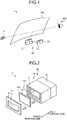
- FIG. 1 is a perspective view illustrating a schematic structure of a vehicle display device according to an embodiment
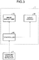
- FIG. 2 is a perspective view of a display device and a light source according to the embodiment
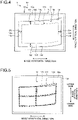
- FIG. 3 is a block diagram of the vehicle display device according to the embodiment
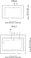
- FIG. 4 is a front view of the display device according to the embodiment
- FIG. 5 is a front view illustrating an example of a plurality of regions according to the embodiment
- FIG. 6 is a diagram illustrating an image visually recognized by a vehicle occupant in the embodiment
- FIG. 7 is a front view of a display device according to a comparative example
- FIG. 1 is a perspective view illustrating a schematic structure of a vehicle display device according to an embodiment
- FIG. 2 is a perspective view of a display device and a light source according to the embodiment
- FIG. 3 is a block diagram of the vehicle display device according to the embodiment
- FIG. 4 is a front view of the display device according to the embodiment
- FIG. 5 is a front view
- FIG. 8 is a diagram illustrating an image visually recognized by the vehicle occupant in the comparative example
- FIG. 9 is a diagram for explaining a method for determining the shape of an opening
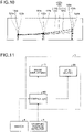
- FIG. 10 is a diagram for explaining a method for determining a comprehensive region.
- a vehicle display device 1 includes a projection device 30.
- the projection device 30 includes a display device 10, a light source 20, and a mirror 2.
- the display device 10 includes a housing 11, an image display unit 12, and a cover 13.
- the housing 11 and the cover 13 are light-shielding members, and formed of, for example, metal.
- the housing 11 is a tubular member having a rectangular sectional shape.
- the image display unit 12 generates and displays an image.
- the image display unit 12 is, for example, a liquid crystal display device, such as a thin film transistorliquid crystal display (TFT-LCD).
- TFT-LCD thin film transistorliquid crystal display
- the image display unit 12 has light transmittance, and projects an image with light from the light source 20.
- the shape of the image display unit 12 in plan view is, for example, a rectangular shape.
- the image display unit 12 includes a display possible region 12a.
- the display possible region 12a is a region capable of displaying an image in the image display unit 12.
- the shape of the display possible region 12a is, for example, a rectangular shape.
- the display possible region 12a is, for example, approximately the whole surface of the image display unit 12.
- the image display unit 12 is capable of displaying a desired image in a desired region of the display possible region 12a.
- the image display unit 12 is disposed in one opening portion 11a in the housing 11.
- the side on which the image display unit 12 is disposed in the axial direction of the housing 11 is referred to as a "front surface side", and the side opposite to the front surface side is referred to as a "back surface side”.
- the cover 13 covers the image display unit 12 from the front surface side, to close the opening portion 11a.
- the light source 20 emits light to the image display unit 12 from the back surface side.
- the light source 20 of the present embodiment is connected, on the back surface side, with the housing 11 of the display device 10.
- the light source 20 includes a housing 21 and a plurality of light-emitting members arranged inside the housing 21.
- the light-emitting members are light-emitting elements, such as light emitting diodes (LED).
- the light-emitting members are arranged along, for example, the image vertical direction and the image horizontal direction.
- the light-emitting members emit light to the image display unit 12 from the back surface side. With the light emitted from the light-emitting members, the image displayed on the image display unit 12 is projected toward the front surface side.
- the light source 20 may be configured to emit light to the image display unit 12 from the front surface side.
- the light source 20 is disposed inside the housing 11 such that light can be emitted to the image display unit 12 from the front surface side.
- the light source 20 may emit light to the image display unit 12 from both of the front surface side and the back surface side.
- the vehicle display device 1 includes a controller 60.
- the controller 60 controls the image display unit 12 and the light source 20.
- the controller 60 sets an image display region 12b in the image display unit 12.
- the image display region 12b is a region of part of the display possible region 12a.
- the image display region 12b according to the present embodiment is surrounded with a first side 12c, a second side 12d, a third side 12e, and a fourth side 12f.
- the first side 12c and the second side 12d are sides extending along the image horizontal direction.
- the third side 12e and the fourth side 12f are sides extending along the image vertical direction.
- the vehicle display device 1 stores therein a plurality of predetermined regions as candidates for the image display region 12b.
- FIG. 5 illustrates an example of the regions.
- FIG. 5 illustrates a first region 121, a second region 122, and a third region 123.
- the first region 121, the second region 122, and the third region 123 correspond to different viewpoint positions in the vehicle vertical direction.
- the first region 121 is determined such that the shape of the image viewed from a vehicle occupant 200 has a desired shape when the viewpoint position is a first height position.
- the shape of the first region 121 is determined such that, for example, when the display light is emitted from the whole region of the first region 121, the shape of the image formed with the display light has a rectangular shape as viewed from the first height position.
- the second region 122 is determined such that the shape of the image viewed from the vehicle occupant 200 has a desired shape when the viewpoint position is a second height position.
- the third region 123 is determined such that the shape of the image viewed from the vehicle occupant 200 has a desired shape when the viewpoint position is a third height position.
- each of the regions 121, 122, and 123 is designed on the basis of, for example, the surface shape of a windshield WS.
- the shape of the windshield WS according to the present embodiment is a curved shape.
- the shape of each of the regions is determined, on the basis of a surface shape of the portion on which the image is reflected in the windshield WS, to correct distortion of the image generated with the surface shape.
- the shape of each of the regions 121, 122, and 123 is a distorted shape with respect to the desired shape such that the shape of the image visually recognized by the vehicle occupant 200 is a desired shape.
- the second height position may be, for example, an intermediate position between the supposed highest viewpoint position and the supposed lowest viewpoint position.
- the first height position may be one of the supposed highest viewpoint position and the supposed lowest viewpoint position.
- the third height position may be the other of the supposed highest viewpoint position and the supposed lowest viewpoint position.
- the controller 60 sets one of the regions 121, 122, and 123 as the image display region 12b.
- the vehicle display device 1 includes a viewpoint position detector 5.
- the viewpoint position detector 5 detects the viewpoint position of the vehicle occupant 200.
- the vehicle occupant 200 serving as a detection target is typically a driver.
- the viewpoint position detector 5 includes, for example, a camera imaging the face of the vehicle occupant 200 from the front.
- the viewpoint position detector 5 detects the viewpoint position and/or the visual line direction of the vehicle occupant 200 on the basis of image data acquired by imaging the face of the vehicle occupant 200.
- the viewpoint position detector 5 transmits information of the detected viewpoint position to the controller 60.
- the controller 60 sets one of the regions 121, 122, and 123 as the image display region 12b on the basis of the acquired viewpoint position. For example, when the detected viewpoint position is closest to the first height position among the first height position, the second height position, and the third height position, the first region 121 is set as the image display region 12b.
- the controller 60 controls the image display unit 12 to display the image in the set image display region 12b. In this case, the controller 60 controls the image display unit 12 to prevent pixels positioned outside the image display region 12b from transmitting light of the light source 20.
- the cover 13 includes an opening 14.
- the opening 14 is provided in a position in the cover 13 opposed to the image display unit 12.
- the shape of the opening 14 is a shape similar to the shape of the image display region 12b. More specifically, as illustrated in FIG. 4 , the image display region 12b according to the present embodiment is curved toward the upper side in the image vertical direction as the position approaches the fourth side 12f along the image horizontal direction.
- the shape of the opening 14 is a curved shape corresponding to the curved shape of the image display region 12b.
- the opening 14 is curved toward the upper side in the image vertical direction as the position approaches a fourth side 14f along the image horizontal direction.
- the opening 14 is separated from the outer edge of the image display region 12b and surrounds the image display region 12b.
- the outer edge of the image display region 12b is formed of the first side 12c, the second side 12d, the third side 12e, and the fourth side 12f.
- the opening 14 includes a first side 14c, a second side 14d, a third side 14e, and the fourth side 14f.
- the first side 14c, the second side 14d, the third side 14e, and the fourth side 14f correspond to the first side 12c, the second side 12d, the third side 12e, and the fourth side 12f, respectively.
- the shape of the first side 14c of the opening 14 is similar to the shape of the first side 12c of the image display region 12b.
- the first side 14c is separated from the first side 12c in the image vertical direction.
- the shapes of the second side 14d, the third side 14e, and the fourth side 14f are similar to the shapes of the second side 12d, the third side 12e, and the fourth side 12f, respectively.
- the second side 14d is separated from the second side 12d in the image vertical direction.
- the third side 14e and the fourth side 14f are separated from the third side 12e and the fourth side 12f, respectively, in the image horizontal direction.
- the vehicle display device 1 according to the present embodiment has a structure in which the shape of the opening 14 is similar to the shape of the image display region 12b as described above, and tends not to provide the vehicle occupant 200 with troublesomeness or discomfort, as explained hereinafter.
- FIG. 6 illustrates an image 40 that can be caused to be visually recognized by the vehicle occupant 200 with the vehicle display device 1 according to the present embodiment.
- FIG. 7 illustrates a display device 100 according to a comparative example.
- FIG. 8 illustrates an image 50 corresponding to the display device 100 according to the comparative example.
- the shape of the opening 14 is a rectangular shape.
- the display light projected with the vehicle display device 1 is visually recognized as the image 40 by the vehicle occupant 200.
- the shape of the image 40 is a rectangular or a substantially rectangular shape.
- Leakage light 41 exists around the image 40.
- the leakage light 41 is light leaking from a portion outside the image display region 12b.
- light of the light source 20 slightly leaks to the front surface side, even in a portion in which no image is displayed. With the leaking light, the leakage light 41 is faintly viewed around the image 40.
- the background is dark, such as at night, the leakage light 41 tends to be conspicuous.
- the shape of the outer edge of the leakage light 41 depends on the shape of the opening 14.
- the shape of the opening 14 is similar to the shape of the image display region 12b.
- the shape of the outer edge of the image 40 is similar to the shape of the outer edge of the leakage light 41. This structure suppresses a troublesome feeling or sense of discomfort of the vehicle occupant 200 with respect to the leakage light 41.
- the shape of the opening 14 is dissimilar to the shape of the image display region 12b, as illustrated in FIG. 7 .
- the shape of the image display region 12b is a curved shape
- the shape of the opening 14 is a rectangular shape.
- the shape of leakage light 51 is a distorted shape with respect to the shape of the image 50 visually recognized by the vehicle occupant 200. Due to distortion of the shape of the leakage light 51 and/or a non-uniform width of the leakage light 51, the vehicle occupant 200 feels the leakage light 51 troublesome or uncomfortable.
- the vehicle display device 1 according to the present embodiment enables suppression of troublesomeness caused by the leakage light 41.
- the vehicle display device 1 according to the present embodiment has the structure in which the opening 14 is separated from the outer edge of the image display region 12b, and improves visibility of images. For example, due to assembling tolerance, position displacement of the image display unit 12 from the opening 14 may occur in the image vertical direction and/or the image horizontal direction. When such position displacement occurs, the vehicle display device 1 according to the present embodiment prevents the cover 13 from covering of the image display region 12b. In addition, even when the viewpoint position of the vehicle occupant 200 changes along the vehicle vertical direction and/or the vehicle width direction, the cover 13 is prevented from covering the image display region 12b. With this structure, the vehicle display device 1 according to the present embodiment enables improvement in visibility of images.
- FIG. 9 is a diagram for explaining a method for determining the shape of the opening 14.
- the shape of the opening 14 is determined on the basis of a comprehensive region 124 illustrated in FIG. 9 .
- the comprehensive region 124 is a region taking in the first region 121, the second region 122, and the third region 123.
- the shape of the opening 14 is similar to the shape of the comprehensive region 124.
- the comprehensive region 124 includes a first side 124c, a second side 124d, a third side 124e, and a fourth side 124f.
- the four sides 124c, 124d, 124e, and 124f are side corresponding to the four sides 12c, 12d, 12e, and 12f, respectively, of the image display region 12b.
- the first side 124c is determined on the basis of the first side 121c of the first region 121, the first side 122c of the second region 122, and the first side 123c of the third region 123.
- the first side 121c of the first region 121 includes two endpoints 121g and 121h and a middle point 121k.
- the first side 122c of the second region 122 includes two endpoints 122g and 122h and a middle point 122k.
- the first side 123c of the third region 123 includes two endpoints 123g and 123h and a middle point 123k.
- a first point to determine the first side 124c of the comprehensive region 124 is selected from the three endpoints 121g, 122g, and 123g.
- the endpoint 122g located on the uppermost side in the image vertical direction, that is, on the outermost side in the image display unit 12 is selected among the three endpoints 121g, 122g, and 123g.
- the endpoint 121h located on the uppermost side in the image vertical direction, that is, on the outermost side of the image display unit 12 is selected among the three endpoints 121h, 122h, and 123h.
- the middle point 121k located on the uppermost side in the image vertical direction, that is, on the outermost side in the image display unit 12 is selected among the three middle points 121k, 122k, and 123k.
- the first side 124c is determined with the selected first point 122g, the second point 121h, and the third point 121k.
- an arc extending through the three points 122g, 121h, and 121k is set as the first side 124c.
- the set first side 124c is substantially equal to a line connecting outermost points of the three first sides 121c, 122c, and 123c.
- the other three sides 124d, 124e, and 124f surrounding the comprehensive region 124 are determined.
- the comprehensive region 124 according to the present embodiment is a region surrounded with four arcs.
- the comprehensive region 124 determined as described above substantially contains the first region 121, the second region 122, and the third region 123.
- the four sides 124c, 124d, 124e, and 124f of the comprehensive region 124 are lines connecting outermost points of the first region 121, the second region 122, and the third region 123.
- the shape of the opening 14 is a shape similar to the shape of the comprehensive region 124.
- the shape of the opening 14 is, for example, a shape acquired by uniformly expanding the comprehensive region 124 in the image vertical direction and the image horizontal direction.
- the opening 14 is determined such that, for example, an interval G1 between the first side 124c of the comprehensive region 124 and the first side 14c of the opening 14 is uniform or substantially uniform.
- An interval G2 between the second side 124d of the comprehensive region 124 and the second side 14d of the opening 14 may be set uniform or substantially uniform.
- An interval G3 between the third side 124e of the comprehensive region 124 and the third side 14e of the opening 14 may be set uniform or substantially uniform.
- An interval G4 between the fourth side 124f of the comprehensive region 124 and the fourth side 14f of the opening 14 may be set uniform or substantially uniform.
- the four intervals G1, G2, G3, and G4 may be set to the same value.
- the width of the leakage light 41 is equal to or larger than a certain width, even when any of the first region 121, the second region 122, and the third region 123 is set as the image display region 12b. For this reason, when the image display region 12b is switched, the vehicle occupant 200 hardly perceives change in shape of the leakage light 41. This structure suppresses troublesomeness and/or discomfort of the vehicle occupant 200 for the leakage light 41.
- the shape of the opening 14 is similar to the shape of the outer edge of the comprehensive region 124, the shape of the opening 14 can be regarded as similar to each of the shape of the first region 121, the shape of the second region 122, and the shape of the third region 123.
- the first side 14c and the second side 14d of the opening 14 are curved in the same direction.
- the curved shapes of the first side 14c and the second side 14d are similar to, substantially similar to, or analogous to the curved shapes of the corresponding sides of the three regions 121, 122, and 123. Accordingly, even when any of the three regions 121, 122, and 123 is set as the image display region 12b, the vehicle occupant 200 hardly feels the leakage light 41 troublesome.
- the vehicle display device 1 includes the projection device 30 including the image display unit 12, the light source 20, and the cover 13.
- the image display unit 12 has light transmittance and displays an image.
- the light source 20 emits light to the image display unit 12 from the back surface side or the front surface side.
- the cover 13 has a light shielding property and the opening 14, and is disposed on a front surface of the image display unit 12.
- the projection device 30 projects an image onto the windshield WS.
- the windshield WS serves as an example of the reflection unit disposed in front of the vehicle occupant 200 in the vehicle.
- the shape of the opening 14 is a shape similar to the shape of the image display region 12b in the image display unit 12.
- the opening 14 is separated from the outer edge of the image display region 12b and surrounds the image display region 12b.
- the vehicle display device 1 according to the present embodiment can suppress a troublesome feeling for the leakage light 41 around the image display region 12b, because the shape of the image display region 12b is similar to the shape of the opening.
- the shape of the image display region 12b according to the present embodiment is a curved shape with respect to the desired shape such that the shape of the image visually recognized by the vehicle occupant 200 is the desired shape.
- the sides 14c, 14d, 14e, and 14f of the opening 14 are curved in the same manner as the corresponding sides 12c, 12d, 12e, and 12f of the image display region 12b. Accordingly, the shape of the image visually recognized by the vehicle occupant 200 is set to the desired shape, and the outer edge shape of the image is set similar to the outer edge shape of the leakage light.
- the vehicle display device 1 according to the present embodiment can suppress a troublesome feeling of the vehicle occupant 200 for the leakage light.
- the vehicle display device 1 further includes the controller 60 controlling the projection device 30 and setting the image display region 12b to one of a plurality of predetermined regions 121, 122, and 123.
- the shape of the opening 14 is similar to the shape of the comprehensive region 124 including the regions 121, 122, and 123. With the shape of the opening 14 similar to the shape of the comprehensive region 124, a troublesome feeling of the vehicle occupant 200 for the leakage light can be suppressed.
- the controller 60 sets the image display region 12b to a region corresponding to the viewpoint position of the vehicle occupant 200 in the regions 121, 122, and 123.
- the shape of the image visually recognized by the vehicle occupant 200 can be set to an optimum shape.
- FIG. 11 is a block diagram of the vehicle display device according to the first modification of the embodiment
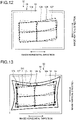
- FIG. 12 is a diagram illustrating a plurality of regions according to the first modification of the embodiment
- FIG. 13 is a diagram illustrating the comprehensive region according to the first modification of the embodiment.
- the first modification of the embodiment is different from the embodiment described above in that, for example, a plurality of regions are set to regulate the inclination of the image.
- the vehicle display device 1 includes a switch 6.
- the switch 6 is a switch on which an operation input is performed by the vehicle occupant 200. A signal indicating an operation input to the switch 6 is transmitted to the controller 60.
- the switch 6 may be a physical switch mechanism or a touch switch displayed on a touch panel or the like.
- the switch 6 is a switch to regulate the inclination of the image displayed with the vehicle display device 1.
- the vehicle display device 1 rotates the image clockwise or counterclockwise in response to the operation input to the switch 6.
- a fourth region 125, a fifth region 126, and a sixth region 127 are set as candidates for the image display region 12b.
- the fifth region 126 may be the same region as the second region 122 of the embodiment described above.
- the fourth region 125 and the sixth region 127 are regions acquired by rotating the fifth region 126.
- the fourth region 125 is a region acquired by rotating the fifth region 126 by a predetermined angle counterclockwise in FIG. 12 .
- the sixth region 127 is a region acquired by rotating the fifth region 126 by a predetermined angle clockwise in FIG. 12 .
- the fourth region 125, the fifth region 126, and the sixth region 127 have a substantially common center position.
- the shapes of the fourth region 125, the fifth region 126, and the sixth region 127 are substantially the same. Accordingly, the fourth region 125, the fifth region 126, and the sixth region 127 are regions having substantially the same shape and mutually different inclination angles with respect to the horizontal direction of the image display unit 12.
- the controller 60 sets any of the fourth region 125, the fifth region 126, and the sixth region 127 as the image display region 12b, in response to an operation input to the switch 6.
- the image display region 12b is switched from one of the three regions 125, 126, and 127 to another region thereof, the image visually recognized by the vehicle occupant 200 rotates clockwise or counterclockwise. In other words, the inclination of the image with respect to the vehicle width direction is changed by switching the image display region 12b from one of the three regions 125, 126, and 127 to another region thereof.
- a comprehensive region 128 according to the first modification of the embodiment is a region including the fourth region 125, the fifth region 126, and the sixth region 127.
- a method for determining the comprehensive region 128 is substantially the same as the method for determining the comprehensive region 124 according to the embodiment described above. Specifically, external borderlines in the comprehensive region 128 are determined to connect outermost points of the three regions 125, 126, and 127.
- the shape of the opening 14 is similar to the shape of the comprehensive region 128. The opening 14 is separated from the outer edge of the comprehensive region 128 and surrounds the comprehensive region 128. An interval G6 between the opening 14 and the outer edge of the comprehensive region 128 is, for example, fixed.
- the vehicle display device 1 enables suppression of a troublesome feeling of the vehicle occupant 200 for the leakage light, while achieving the function of regulating the inclination of the image.
- the fourth region 125, the fifth region 126, and the sixth region 127 illustrated above enable regulation of the inclination of the image clockwise and counterclockwise by one grade, but the number of grades of regulation is not limited thereto.
- five or more regions may be set to enable regulation of the inclination of the image clockwise and counterclockwise by two or more grades.
- the shapes of the fourth region 125, the fifth region 126, and the sixth region 127 are not necessarily the same.
- the shapes of the fourth region 125, the fifth region 126, and the sixth region 127 may be mutually different.
- the vehicle display device 1 may be configured to achieve both setting of the image display region 12b in accordance with the viewpoint position and setting of the image display region 12b to regulate the inclination of the image.
- regions to regulate the inclination of the image may be provided for each of the first region 121, the second region 122, and the third region 123.
- a plurality of regions having the same shape as that of the first region 121 and inclination angles different from that of the first region 121 may be prepared for the first region 121.
- a plurality of regions having the same shape and different inclination angles may be prepared for each of the second region 122 and the third region 123.
- the comprehensive region is determined to include all the regions.
- the vehicle display device 1 may include a mechanism to change the angle of the mirror 2.
- the mechanism to change the angle of the mirror 2 includes a motor.
- the vehicle display device 1 may change the angle of the mirror 2 by an operation by the vehicle occupant 200, or change the angle of the mirror 2 in accordance with a detection result of the viewpoint position detector 5.
- the controller 60 may change the image display region 12b in accordance with the angle of the mirror 2. For example, in the embodiment described above, the controller 60 sets one of the first region 121, the second region 122, and the third region 123 as the image display region 12b, in accordance with the angle of the mirror 2.
- the method for determining the shape of the opening 14 is not limited to the method illustrated in the embodiment and the like.
- the shape of the opening 14 may be a shape similar to an intermediate line, instead of the shape similar to the shape of the comprehensive region 124 or 128.
- an intermediate line is determined on the basis of a line surrounding the three regions 121, 122, and 123.
- the intermediate line is set to a line connecting intermediate points between the outermost line and the innermost line in the lines surrounding the three regions 121, 122, and 123.
- the shape of the opening 14 may be set to a shape similar to the shape of the image display region 12b in the case where the viewpoint position is in an intermediate position in the vehicle vertical direction. For example, in the embodiment described above, suppose that the second height position is an intermediate position between the supposed highest viewpoint position and the supposed lowest viewpoint position in the viewpoint positions. In this case, the shape of the opening 14 may be set to a shape similar to the shape of the second region 122.
- the shape of the opening 14 may be set to a shape similar to the shape of the image display region 12b in the case where the viewpoint position is a standard position in the vehicle vertical direction. For example, in the embodiment described above, suppose that a standard height position in the vehicle vertical direction is the second height position. In this case, the shape of the opening 14 may be set to a shape similar to the shape of the second region 122.
- the shape of the opening 14 may be determined on the basis of the image display region 12b of one type. Specifically, when the image display region 12b has only one shape, the shape of the opening 14 may be set to a shape similar to the shape of the image display region 12b.
- the regions 121, 122, and 123 do not necessarily correspond to the viewpoint positions.
- the vehicle display device 1 may be configured such that the vehicle occupant 200 can select the shape of the image display region 12b as desired from the regions 121, 122, and 123.
- the image display region 12b is switched to any region in the regions 121, 122, and 123.
- the vehicle occupant 200 selects a region with which the appearance of the image becomes optimum for the vehicle occupant 200 from the regions 121, 122, and 123.
- the regions 121, 122, and 123 may be set to have mutually different correction degrees to correct the distortion of the image.
- the first region 121 may have the highest correction degree to correct distortion
- the third region 123 may have the lowest correction degree to correct distortion.
- the shape of the image 40 (see FIG. 6 ) visually recognized by the vehicle occupant 200 is not limited to a rectangular shape.
- the shape of the image display region visually recognized by the vehicle occupant 200 may be a shape other than a rectangular shape.
- the shape of the image 40 may be a shape acquired by combining a plurality of rectangles, or a polygonal shape other than a rectangular shape.
- the method for determining the comprehensive region is not limited to the method illustrated in the embodiment.
- the shape of the comprehensive region is properly determined to reduce or remove the occupant's troublesomeness for the leakage light 41.
- the number of regions is not limited to three illustrated above.
- the number of regions may be two or four or more.
- the reflection unit serving as the target onto which the image is projected is not limited to the windshield WS.
- the reflection unit may be a combiner or the like disposed in front of the vehicle occupant.
- the reflection unit may be a half mirror or the like provided in a meter device disposed in front of the vehicle occupant.
- the vehicle display device includes a projection device including a light-transmitting image display unit displaying an image, a light source emitting light to the image display unit from a back surface side or a front surface side, and a light-shielding cover disposed on a front surface of the image display unit and including an opening.
- the projection device projects an image onto a reflection unit disposed in front of a vehicle occupant in a vehicle.
- a shape of the opening is a shape similar to a shape of an image display region in the image display unit, and the opening is separated from an outer edge of the image display region and surrounds the image display region.
- the vehicle display device according to the present embodiment has the structure in which the shape of the opening is similar to the shape of the image display region, and produces the effect of suppressing the vehicle occupant's troublesome feeling for leakage light.
Landscapes
- Engineering & Computer Science (AREA)
- Mechanical Engineering (AREA)
- Physics & Mathematics (AREA)
- Chemical & Material Sciences (AREA)
- Combustion & Propulsion (AREA)
- Transportation (AREA)
- General Physics & Mathematics (AREA)
- Optics & Photonics (AREA)
- Multimedia (AREA)
- Instrument Panels (AREA)
- Fittings On The Vehicle Exterior For Carrying Loads, And Devices For Holding Or Mounting Articles (AREA)
Description
- The present invention relates to a vehicle display device.
- In related art, in vehicle display devices, there is a technique of suppressing distortion of an image.
Japanese Patent Application Laid-open No. 2003-107391 - When an image is projected by emitting light to the image display unit, such as a liquid crystal display, from the back surface side thereof, light leakage in which the light of the light source leaks to the front surface side occurs outside the region displaying the image. The vehicle occupant may feel the leakage light troublesome. For example, when the shape of the leakage light is distorted, the vehicle occupant may feel the leakage light troublesome.
- Document
JP 2018 075983 A - An object of the present invention is to provide a vehicle display device suppressing the vehicle occupant's troublesome feeling for leakage light.
- This is achieved by the features of the independent claims.
- The above and other objects, features, advantages and technical and industrial significance of this invention will be better understood by reading the following detailed description of presently preferred embodiments of the invention, when considered in connection with the accompanying drawings.
-
-
FIG. 1 is a perspective view illustrating a schematic structure of a vehicle display device according to an embodiment; -
FIG. 2 is a perspective view of a display device and a light source according to the embodiment; -
FIG. 3 is a block diagram of the vehicle display device according to the embodiment; -
FIG. 4 is a front view of the display device according to the embodiment; -
FIG. 5 is a front view illustrating an example of a plurality of regions according to the embodiment; -
FIG. 6 is a diagram illustrating an image visually recognized by a vehicle occupant in the embodiment; -
FIG. 7 is a front view of a display device according to a comparative example; -
FIG. 8 is a diagram illustrating an image visually recognized by the vehicle occupant in the comparative example; -
FIG. 9 is a diagram for explaining a method for determining the shape of an opening; -
FIG. 10 is a diagram for explaining a method for determining a comprehensive region; -
FIG. 11 is a block diagram of the vehicle display device according to a first modification of the embodiment; -
FIG. 12 is a diagram illustrating a plurality of regions according to the first modification of the embodiment; and -
FIG. 13 is a diagram illustrating a comprehensive region according to the first modification of the embodiment. - The following is a detailed explanation of a vehicle display device according to an embodiment of the present invention with reference to drawings. The present invention is not limited to the embodiment but is defined by the appended claims.
- An embodiment will now be described with reference to
FIG. 1 to FIG. 10 . The present embodiment relates to a vehicle display device.FIG. 1 is a perspective view illustrating a schematic structure of a vehicle display device according to an embodiment,FIG. 2 is a perspective view of a display device and a light source according to the embodiment,FIG. 3 is a block diagram of the vehicle display device according to the embodiment,FIG. 4 is a front view of the display device according to the embodiment,FIG. 5 is a front view illustrating an example of a plurality of regions according to the embodiment,FIG. 6 is a diagram illustrating an image visually recognized by a vehicle occupant in the embodiment,FIG. 7 is a front view of a display device according to a comparative example,FIG. 8 is a diagram illustrating an image visually recognized by the vehicle occupant in the comparative example,FIG. 9 is a diagram for explaining a method for determining the shape of an opening, andFIG. 10 is a diagram for explaining a method for determining a comprehensive region. - As illustrated in
FIG. 1 , avehicle display device 1 according to the present embodiment includes aprojection device 30. Theprojection device 30 includes adisplay device 10, alight source 20, and amirror 2. As illustrated inFIG. 2 , thedisplay device 10 includes ahousing 11, animage display unit 12, and acover 13. Thehousing 11 and thecover 13 are light-shielding members, and formed of, for example, metal. Thehousing 11 is a tubular member having a rectangular sectional shape. - The
image display unit 12 generates and displays an image. Theimage display unit 12 is, for example, a liquid crystal display device, such as a thin film transistorliquid crystal display (TFT-LCD). Theimage display unit 12 has light transmittance, and projects an image with light from thelight source 20. The shape of theimage display unit 12 in plan view is, for example, a rectangular shape. Theimage display unit 12 includes a displaypossible region 12a. The displaypossible region 12a is a region capable of displaying an image in theimage display unit 12. The shape of the displaypossible region 12a is, for example, a rectangular shape. The displaypossible region 12a is, for example, approximately the whole surface of theimage display unit 12. Theimage display unit 12 is capable of displaying a desired image in a desired region of the displaypossible region 12a. - As illustrated in
FIG. 2 , theimage display unit 12 is disposed in one openingportion 11a in thehousing 11. In the following explanation, the side on which theimage display unit 12 is disposed in the axial direction of thehousing 11 is referred to as a "front surface side", and the side opposite to the front surface side is referred to as a "back surface side". Thecover 13 covers theimage display unit 12 from the front surface side, to close theopening portion 11a. - The
light source 20 emits light to theimage display unit 12 from the back surface side. Thelight source 20 of the present embodiment is connected, on the back surface side, with thehousing 11 of thedisplay device 10. Thelight source 20 includes ahousing 21 and a plurality of light-emitting members arranged inside thehousing 21. The light-emitting members are light-emitting elements, such as light emitting diodes (LED). The light-emitting members are arranged along, for example, the image vertical direction and the image horizontal direction. The light-emitting members emit light to theimage display unit 12 from the back surface side. With the light emitted from the light-emitting members, the image displayed on theimage display unit 12 is projected toward the front surface side. Thelight source 20 may be configured to emit light to theimage display unit 12 from the front surface side. In this case, for example, thelight source 20 is disposed inside thehousing 11 such that light can be emitted to theimage display unit 12 from the front surface side. Thelight source 20 may emit light to theimage display unit 12 from both of the front surface side and the back surface side. - As illustrated in
FIG. 3 , thevehicle display device 1 includes a controller 60. The controller 60 controls theimage display unit 12 and thelight source 20. The controller 60 sets animage display region 12b in theimage display unit 12. As illustrated inFIG. 4 , theimage display region 12b is a region of part of the displaypossible region 12a. Theimage display region 12b according to the present embodiment is surrounded with afirst side 12c, asecond side 12d, a third side 12e, and afourth side 12f. Thefirst side 12c and thesecond side 12d are sides extending along the image horizontal direction. The third side 12e and thefourth side 12f are sides extending along the image vertical direction. - The
vehicle display device 1 according to the present embodiment stores therein a plurality of predetermined regions as candidates for theimage display region 12b.FIG. 5 illustrates an example of the regions.FIG. 5 illustrates afirst region 121, asecond region 122, and athird region 123. Thefirst region 121, thesecond region 122, and thethird region 123 correspond to different viewpoint positions in the vehicle vertical direction. - The
first region 121 is determined such that the shape of the image viewed from avehicle occupant 200 has a desired shape when the viewpoint position is a first height position. The shape of thefirst region 121 is determined such that, for example, when the display light is emitted from the whole region of thefirst region 121, the shape of the image formed with the display light has a rectangular shape as viewed from the first height position. Thesecond region 122 is determined such that the shape of the image viewed from thevehicle occupant 200 has a desired shape when the viewpoint position is a second height position. In the same manner, thethird region 123 is determined such that the shape of the image viewed from thevehicle occupant 200 has a desired shape when the viewpoint position is a third height position. - The shape of each of the
regions regions vehicle occupant 200 is a desired shape. - The second height position may be, for example, an intermediate position between the supposed highest viewpoint position and the supposed lowest viewpoint position. The first height position may be one of the supposed highest viewpoint position and the supposed lowest viewpoint position. The third height position may be the other of the supposed highest viewpoint position and the supposed lowest viewpoint position.
- The controller 60 sets one of the
regions image display region 12b. As illustrated inFIG. 3 , thevehicle display device 1 according to the present embodiment includes aviewpoint position detector 5. Theviewpoint position detector 5 detects the viewpoint position of thevehicle occupant 200. Thevehicle occupant 200 serving as a detection target is typically a driver. Theviewpoint position detector 5 includes, for example, a camera imaging the face of thevehicle occupant 200 from the front. Theviewpoint position detector 5 detects the viewpoint position and/or the visual line direction of thevehicle occupant 200 on the basis of image data acquired by imaging the face of thevehicle occupant 200. Theviewpoint position detector 5 transmits information of the detected viewpoint position to the controller 60. - The controller 60 sets one of the
regions image display region 12b on the basis of the acquired viewpoint position. For example, when the detected viewpoint position is closest to the first height position among the first height position, the second height position, and the third height position, thefirst region 121 is set as theimage display region 12b. The controller 60 controls theimage display unit 12 to display the image in the setimage display region 12b. In this case, the controller 60 controls theimage display unit 12 to prevent pixels positioned outside theimage display region 12b from transmitting light of thelight source 20. - As illustrated in
FIG. 2 andFIG. 4 , thecover 13 according to the present embodiment includes anopening 14. Theopening 14 is provided in a position in thecover 13 opposed to theimage display unit 12. The shape of theopening 14 is a shape similar to the shape of theimage display region 12b. More specifically, as illustrated inFIG. 4 , theimage display region 12b according to the present embodiment is curved toward the upper side in the image vertical direction as the position approaches thefourth side 12f along the image horizontal direction. The shape of theopening 14 is a curved shape corresponding to the curved shape of theimage display region 12b. Theopening 14 is curved toward the upper side in the image vertical direction as the position approaches afourth side 14f along the image horizontal direction. - The
opening 14 is separated from the outer edge of theimage display region 12b and surrounds theimage display region 12b. The outer edge of theimage display region 12b is formed of thefirst side 12c, thesecond side 12d, the third side 12e, and thefourth side 12f. Theopening 14 includes afirst side 14c, asecond side 14d, athird side 14e, and thefourth side 14f. Thefirst side 14c, thesecond side 14d, thethird side 14e, and thefourth side 14f correspond to thefirst side 12c, thesecond side 12d, the third side 12e, and thefourth side 12f, respectively. - As illustrated in
FIG. 4 , when theprojection device 30 is viewed from the front surface side, the shape of thefirst side 14c of theopening 14 is similar to the shape of thefirst side 12c of theimage display region 12b. In addition, thefirst side 14c is separated from thefirst side 12c in the image vertical direction. - In the same manner, the shapes of the
second side 14d, thethird side 14e, and thefourth side 14f are similar to the shapes of thesecond side 12d, the third side 12e, and thefourth side 12f, respectively. In addition, thesecond side 14d is separated from thesecond side 12d in the image vertical direction. Thethird side 14e and thefourth side 14f are separated from the third side 12e and thefourth side 12f, respectively, in the image horizontal direction. - The
vehicle display device 1 according to the present embodiment has a structure in which the shape of theopening 14 is similar to the shape of theimage display region 12b as described above, and tends not to provide thevehicle occupant 200 with troublesomeness or discomfort, as explained hereinafter.FIG. 6 illustrates animage 40 that can be caused to be visually recognized by thevehicle occupant 200 with thevehicle display device 1 according to the present embodiment.FIG. 7 illustrates adisplay device 100 according to a comparative example.FIG. 8 illustrates animage 50 corresponding to thedisplay device 100 according to the comparative example. As illustrated inFIG. 7 , in thedisplay device 100 according to the comparative example, the shape of theopening 14 is a rectangular shape. - As illustrated in
FIG. 6 , the display light projected with thevehicle display device 1 according to the present embodiment is visually recognized as theimage 40 by thevehicle occupant 200. When the whole region of theimage display region 12b projects the display light, the shape of theimage 40 is a rectangular or a substantially rectangular shape.Leakage light 41 exists around theimage 40. Theleakage light 41 is light leaking from a portion outside theimage display region 12b. In theimage display unit 12, light of thelight source 20 slightly leaks to the front surface side, even in a portion in which no image is displayed. With the leaking light, theleakage light 41 is faintly viewed around theimage 40. When the background is dark, such as at night, theleakage light 41 tends to be conspicuous. - The shape of the outer edge of the
leakage light 41 depends on the shape of theopening 14. In the present embodiment, the shape of theopening 14 is similar to the shape of theimage display region 12b. For this reason, as illustrated inFIG. 6 , the shape of the outer edge of theimage 40 is similar to the shape of the outer edge of theleakage light 41. This structure suppresses a troublesome feeling or sense of discomfort of thevehicle occupant 200 with respect to theleakage light 41. - By contrast, in the
display device 100 according to the comparative example, the shape of theopening 14 is dissimilar to the shape of theimage display region 12b, as illustrated inFIG. 7 . Specifically, while the shape of theimage display region 12b is a curved shape, the shape of theopening 14 is a rectangular shape. As a result, as illustrated inFIG. 8 , the shape ofleakage light 51 is a distorted shape with respect to the shape of theimage 50 visually recognized by thevehicle occupant 200. Due to distortion of the shape of theleakage light 51 and/or a non-uniform width of theleakage light 51, thevehicle occupant 200 feels theleakage light 51 troublesome or uncomfortable. - As described above, the
vehicle display device 1 according to the present embodiment enables suppression of troublesomeness caused by theleakage light 41. In addition, thevehicle display device 1 according to the present embodiment has the structure in which theopening 14 is separated from the outer edge of theimage display region 12b, and improves visibility of images. For example, due to assembling tolerance, position displacement of theimage display unit 12 from theopening 14 may occur in the image vertical direction and/or the image horizontal direction. When such position displacement occurs, thevehicle display device 1 according to the present embodiment prevents thecover 13 from covering of theimage display region 12b. In addition, even when the viewpoint position of thevehicle occupant 200 changes along the vehicle vertical direction and/or the vehicle width direction, thecover 13 is prevented from covering theimage display region 12b. With this structure, thevehicle display device 1 according to the present embodiment enables improvement in visibility of images. - The following is an explanation of an example of a method for determining the shape of the
opening 14.FIG. 9 is a diagram for explaining a method for determining the shape of theopening 14. In the present embodiment, the shape of theopening 14 is determined on the basis of acomprehensive region 124 illustrated inFIG. 9 . Thecomprehensive region 124 is a region taking in thefirst region 121, thesecond region 122, and thethird region 123. The shape of theopening 14 is similar to the shape of thecomprehensive region 124. Thecomprehensive region 124 includes afirst side 124c, asecond side 124d, athird side 124e, and afourth side 124f. The foursides sides image display region 12b. - The following is an explanation of a method for determining the
first side 124c of thecomprehensive region 124, with reference toFIG. 10 . Thefirst side 124c is determined on the basis of the first side 121c of thefirst region 121, thefirst side 122c of thesecond region 122, and the first side 123c of thethird region 123. The first side 121c of thefirst region 121 includes twoendpoints 121g and 121h and a middle point 121k. Thefirst side 122c of thesecond region 122 includes twoendpoints middle point 122k. The first side 123c of thethird region 123 includes twoendpoints - In the present embodiment, a first point to determine the
first side 124c of thecomprehensive region 124 is selected from the threeendpoints endpoint 122g located on the uppermost side in the image vertical direction, that is, on the outermost side in theimage display unit 12 is selected among the threeendpoints first side 124c, the endpoint 121h located on the uppermost side in the image vertical direction, that is, on the outermost side of theimage display unit 12 is selected among the threeendpoints first side 124c, the middle point 121k located on the uppermost side in the image vertical direction, that is, on the outermost side in theimage display unit 12 is selected among the threemiddle points 121k, 122k, and 123k. - The
first side 124c is determined with the selectedfirst point 122g, the second point 121h, and the third point 121k. In the present embodiment, an arc extending through the threepoints 122g, 121h, and 121k is set as thefirst side 124c. The setfirst side 124c is substantially equal to a line connecting outermost points of the threefirst sides 121c, 122c, and 123c. By a similar method, the other threesides comprehensive region 124 are determined. Specifically, thecomprehensive region 124 according to the present embodiment is a region surrounded with four arcs. Thecomprehensive region 124 determined as described above substantially contains thefirst region 121, thesecond region 122, and thethird region 123. In addition, the foursides comprehensive region 124 are lines connecting outermost points of thefirst region 121, thesecond region 122, and thethird region 123. - The shape of the
opening 14 is a shape similar to the shape of thecomprehensive region 124. The shape of theopening 14 is, for example, a shape acquired by uniformly expanding thecomprehensive region 124 in the image vertical direction and the image horizontal direction. Theopening 14 is determined such that, for example, an interval G1 between thefirst side 124c of thecomprehensive region 124 and thefirst side 14c of theopening 14 is uniform or substantially uniform. An interval G2 between thesecond side 124d of thecomprehensive region 124 and thesecond side 14d of theopening 14 may be set uniform or substantially uniform. An interval G3 between thethird side 124e of thecomprehensive region 124 and thethird side 14e of theopening 14 may be set uniform or substantially uniform. An interval G4 between thefourth side 124f of thecomprehensive region 124 and thefourth side 14f of theopening 14 may be set uniform or substantially uniform. The four intervals G1, G2, G3, and G4 may be set to the same value. - With the shape of the
opening 14 similar to the shape of the outer edge of thecomprehensive region 124, the width of theleakage light 41 is equal to or larger than a certain width, even when any of thefirst region 121, thesecond region 122, and thethird region 123 is set as theimage display region 12b. For this reason, when theimage display region 12b is switched, thevehicle occupant 200 hardly perceives change in shape of theleakage light 41. This structure suppresses troublesomeness and/or discomfort of thevehicle occupant 200 for theleakage light 41. - In addition, because the shape of the
opening 14 is similar to the shape of the outer edge of thecomprehensive region 124, the shape of theopening 14 can be regarded as similar to each of the shape of thefirst region 121, the shape of thesecond region 122, and the shape of thethird region 123. For example, as illustrated inFIG. 9 , thefirst side 14c and thesecond side 14d of theopening 14 are curved in the same direction. The curved shapes of thefirst side 14c and thesecond side 14d are similar to, substantially similar to, or analogous to the curved shapes of the corresponding sides of the threeregions regions image display region 12b, thevehicle occupant 200 hardly feels theleakage light 41 troublesome. - As described above, the
vehicle display device 1 according to the present embodiment includes theprojection device 30 including theimage display unit 12, thelight source 20, and thecover 13. Theimage display unit 12 has light transmittance and displays an image. Thelight source 20 emits light to theimage display unit 12 from the back surface side or the front surface side. Thecover 13 has a light shielding property and theopening 14, and is disposed on a front surface of theimage display unit 12. Theprojection device 30 projects an image onto the windshield WS. The windshield WS serves as an example of the reflection unit disposed in front of thevehicle occupant 200 in the vehicle. - When the
projection device 30 is viewed from the front surface side, the shape of theopening 14 is a shape similar to the shape of theimage display region 12b in theimage display unit 12. In addition, when theprojection device 30 is viewed from the front surface side, theopening 14 is separated from the outer edge of theimage display region 12b and surrounds theimage display region 12b. Thevehicle display device 1 according to the present embodiment can suppress a troublesome feeling for theleakage light 41 around theimage display region 12b, because the shape of theimage display region 12b is similar to the shape of the opening. - The shape of the
image display region 12b according to the present embodiment is a curved shape with respect to the desired shape such that the shape of the image visually recognized by thevehicle occupant 200 is the desired shape. Thesides opening 14 are curved in the same manner as the correspondingsides image display region 12b. Accordingly, the shape of the image visually recognized by thevehicle occupant 200 is set to the desired shape, and the outer edge shape of the image is set similar to the outer edge shape of the leakage light. As a result, thevehicle display device 1 according to the present embodiment can suppress a troublesome feeling of thevehicle occupant 200 for the leakage light. - The
vehicle display device 1 according to the present embodiment further includes the controller 60 controlling theprojection device 30 and setting theimage display region 12b to one of a plurality ofpredetermined regions opening 14 is similar to the shape of thecomprehensive region 124 including theregions opening 14 similar to the shape of thecomprehensive region 124, a troublesome feeling of thevehicle occupant 200 for the leakage light can be suppressed. - The controller 60 according to the present embodiment sets the
image display region 12b to a region corresponding to the viewpoint position of thevehicle occupant 200 in theregions image display region 12b in accordance with the viewpoint position, the shape of the image visually recognized by thevehicle occupant 200 can be set to an optimum shape. - A first modification of the embodiment will now be described.
FIG. 11 is a block diagram of the vehicle display device according to the first modification of the embodiment,FIG. 12 is a diagram illustrating a plurality of regions according to the first modification of the embodiment, andFIG. 13 is a diagram illustrating the comprehensive region according to the first modification of the embodiment. The first modification of the embodiment is different from the embodiment described above in that, for example, a plurality of regions are set to regulate the inclination of the image. - As illustrated in
FIG. 11 , thevehicle display device 1 according to the first modification of the embodiment includes aswitch 6. Theswitch 6 is a switch on which an operation input is performed by thevehicle occupant 200. A signal indicating an operation input to theswitch 6 is transmitted to the controller 60. Theswitch 6 may be a physical switch mechanism or a touch switch displayed on a touch panel or the like. Theswitch 6 is a switch to regulate the inclination of the image displayed with thevehicle display device 1. Thevehicle display device 1 rotates the image clockwise or counterclockwise in response to the operation input to theswitch 6. - As illustrated in
FIG. 12 , afourth region 125, afifth region 126, and asixth region 127 are set as candidates for theimage display region 12b. Thefifth region 126 may be the same region as thesecond region 122 of the embodiment described above. Thefourth region 125 and thesixth region 127 are regions acquired by rotating thefifth region 126. For example, thefourth region 125 is a region acquired by rotating thefifth region 126 by a predetermined angle counterclockwise inFIG. 12 . Thesixth region 127 is a region acquired by rotating thefifth region 126 by a predetermined angle clockwise inFIG. 12 . Thefourth region 125, thefifth region 126, and thesixth region 127 have a substantially common center position. In the present embodiment, the shapes of thefourth region 125, thefifth region 126, and thesixth region 127 are substantially the same. Accordingly, thefourth region 125, thefifth region 126, and thesixth region 127 are regions having substantially the same shape and mutually different inclination angles with respect to the horizontal direction of theimage display unit 12. - The controller 60 sets any of the
fourth region 125, thefifth region 126, and thesixth region 127 as theimage display region 12b, in response to an operation input to theswitch 6. When theimage display region 12b is switched from one of the threeregions vehicle occupant 200 rotates clockwise or counterclockwise. In other words, the inclination of the image with respect to the vehicle width direction is changed by switching theimage display region 12b from one of the threeregions - As illustrated in
FIG. 13 , acomprehensive region 128 according to the first modification of the embodiment is a region including thefourth region 125, thefifth region 126, and thesixth region 127. A method for determining thecomprehensive region 128 is substantially the same as the method for determining thecomprehensive region 124 according to the embodiment described above. Specifically, external borderlines in thecomprehensive region 128 are determined to connect outermost points of the threeregions opening 14 is similar to the shape of thecomprehensive region 128. Theopening 14 is separated from the outer edge of thecomprehensive region 128 and surrounds thecomprehensive region 128. An interval G6 between theopening 14 and the outer edge of thecomprehensive region 128 is, for example, fixed. - The
vehicle display device 1 according to the first modification of the embodiment enables suppression of a troublesome feeling of thevehicle occupant 200 for the leakage light, while achieving the function of regulating the inclination of the image. - With the
fourth region 125, thefifth region 126, and thesixth region 127 illustrated above enable regulation of the inclination of the image clockwise and counterclockwise by one grade, but the number of grades of regulation is not limited thereto. For example, five or more regions may be set to enable regulation of the inclination of the image clockwise and counterclockwise by two or more grades. - The shapes of the
fourth region 125, thefifth region 126, and thesixth region 127 are not necessarily the same. For example, the shapes of thefourth region 125, thefifth region 126, and thesixth region 127 may be mutually different. - The
vehicle display device 1 may be configured to achieve both setting of theimage display region 12b in accordance with the viewpoint position and setting of theimage display region 12b to regulate the inclination of the image. For example, regions to regulate the inclination of the image may be provided for each of thefirst region 121, thesecond region 122, and thethird region 123. For example, a plurality of regions having the same shape as that of thefirst region 121 and inclination angles different from that of thefirst region 121 may be prepared for thefirst region 121. In the same manner, a plurality of regions having the same shape and different inclination angles may be prepared for each of thesecond region 122 and thethird region 123. In this case, it is preferable that the comprehensive region is determined to include all the regions. - A second modification of the embodiment will now be described. The
vehicle display device 1 may include a mechanism to change the angle of themirror 2. For example, the mechanism to change the angle of themirror 2 includes a motor. Thevehicle display device 1 may change the angle of themirror 2 by an operation by thevehicle occupant 200, or change the angle of themirror 2 in accordance with a detection result of theviewpoint position detector 5. - The controller 60 may change the
image display region 12b in accordance with the angle of themirror 2. For example, in the embodiment described above, the controller 60 sets one of thefirst region 121, thesecond region 122, and thethird region 123 as theimage display region 12b, in accordance with the angle of themirror 2. - The method for determining the shape of the
opening 14 is not limited to the method illustrated in the embodiment and the like. For example, the shape of theopening 14 may be a shape similar to an intermediate line, instead of the shape similar to the shape of thecomprehensive region regions regions regions - The shape of the
opening 14 may be set to a shape similar to the shape of theimage display region 12b in the case where the viewpoint position is in an intermediate position in the vehicle vertical direction. For example, in the embodiment described above, suppose that the second height position is an intermediate position between the supposed highest viewpoint position and the supposed lowest viewpoint position in the viewpoint positions. In this case, the shape of theopening 14 may be set to a shape similar to the shape of thesecond region 122. - The shape of the
opening 14 may be set to a shape similar to the shape of theimage display region 12b in the case where the viewpoint position is a standard position in the vehicle vertical direction. For example, in the embodiment described above, suppose that a standard height position in the vehicle vertical direction is the second height position. In this case, the shape of theopening 14 may be set to a shape similar to the shape of thesecond region 122. - In the
vehicle display device 1 having no mechanism to change theimage display region 12b, the shape of theopening 14 may be determined on the basis of theimage display region 12b of one type. Specifically, when theimage display region 12b has only one shape, the shape of theopening 14 may be set to a shape similar to the shape of theimage display region 12b. - A fourth embodiment of the embodiment will now be described. In the embodiment described above, the
regions vehicle display device 1 may be configured such that thevehicle occupant 200 can select the shape of theimage display region 12b as desired from theregions vehicle occupant 200, theimage display region 12b is switched to any region in theregions vehicle occupant 200 selects a region with which the appearance of the image becomes optimum for thevehicle occupant 200 from theregions - As described above, with the structure to enable the
vehicle occupant 200 to select theimage display region 12b, the visibility of the image is improved. Theregions first region 121 may have the highest correction degree to correct distortion, and thethird region 123 may have the lowest correction degree to correct distortion. - The shape of the image 40 (see
FIG. 6 ) visually recognized by thevehicle occupant 200 is not limited to a rectangular shape. In other words, the shape of the image display region visually recognized by thevehicle occupant 200 may be a shape other than a rectangular shape. For example, the shape of theimage 40 may be a shape acquired by combining a plurality of rectangles, or a polygonal shape other than a rectangular shape. - A sixth modification of the embodiment will now be described. The method for determining the comprehensive region is not limited to the method illustrated in the embodiment. The shape of the comprehensive region is properly determined to reduce or remove the occupant's troublesomeness for the
leakage light 41. - The number of regions is not limited to three illustrated above. For example, in the embodiment and/or the first modification of the embodiment described above, the number of regions may be two or four or more.
- The reflection unit serving as the target onto which the image is projected is not limited to the windshield WS. The reflection unit may be a combiner or the like disposed in front of the vehicle occupant. The reflection unit may be a half mirror or the like provided in a meter device disposed in front of the vehicle occupant.
- The details disclosed in the embodiment and the modifications described above may be carried out in proper combinations.
- The vehicle display device according to the present embodiment includes a projection device including a light-transmitting image display unit displaying an image, a light source emitting light to the image display unit from a back surface side or a front surface side, and a light-shielding cover disposed on a front surface of the image display unit and including an opening. The projection device projects an image onto a reflection unit disposed in front of a vehicle occupant in a vehicle. When the projection device is viewed from the front surface side, a shape of the opening is a shape similar to a shape of an image display region in the image display unit, and the opening is separated from an outer edge of the image display region and surrounds the image display region. The vehicle display device according to the present embodiment has the structure in which the shape of the opening is similar to the shape of the image display region, and produces the effect of suppressing the vehicle occupant's troublesome feeling for leakage light.
- Although the invention has been described with respect to specific embodiments for a complete and clear disclosure, the appended claims are not to be thus limited but are to be construed as embodying all modifications and alternative constructions that may occur to one skilled in the art that fairly fall within the basic teaching herein set forth.
Claims (3)
- A vehicle display device (1) comprising:a projection device (30) including a light-transmitting image display unit (12) displaying an image, a light source (20) emitting light to the image display unit (12) from a back surface side or a front surface side, and a light-shielding cover (13) disposed on a front surface of the image display unit (12) and including an opening (14), the projection device (30) projecting an image onto a reflection unit (WS) disposed in front of an occupant (200) in a vehicle,characterized in thatthe projection device (30) further including a controller (60) configured to control the projection device (30) and to set an image display region (12b), which is a part of a display possible region (12a) in the image display unit (12), to any one of a plurality of predetermined regions, andwhen the projection device (30) is viewed from the front surface side, a shape of the opening (14) is a shape acquired by uniformly expanding, in an image vertical direction and an image horizontal direction, a comprehensive region (124; 128) taking in the predetermined regions in the image display unit (12), and the opening (14) is separated from an outer edge of the comprehensive region (124; 128) so that it surrounds the comprehensive region (124; 128), andthe controller (60) is configured to set the image display region (12b) to a region corresponding to a viewpoint position of the occupant (200) in the regions.
- The vehicle display device (1) according to claim 1, whereinthe shape of the image display region (12b) is a curved shape with respect to a desired shape such that a shape of an image (40) visually recognized by the occupant (200) has the desired shape, andsides of the opening (14) are curved, so as to correspond to corresponding sides of the comprehensive region (124; 128).
- The vehicle display device (1) according to claim 1 or 2, wherein the predetermined regions include two or more regions (125, 126, 127) having substantially the same shape and mutually different inclination angles with respect to a horizontal direction of the image display unit (12).
Applications Claiming Priority (1)
| Application Number | Priority Date | Filing Date | Title |
|---|---|---|---|
| JP2019025234A JP6868047B2 (en) | 2019-02-15 | 2019-02-15 | Vehicle display device |
Publications (2)
| Publication Number | Publication Date |
|---|---|
| EP3696596A1 EP3696596A1 (en) | 2020-08-19 |
| EP3696596B1 true EP3696596B1 (en) | 2022-05-11 |
Family
ID=69581885
Family Applications (1)
| Application Number | Title | Priority Date | Filing Date |
|---|---|---|---|
| EP20156907.6A Active EP3696596B1 (en) | 2019-02-15 | 2020-02-12 | Vehicle display device |
Country Status (4)
| Country | Link |
|---|---|
| US (1) | US11320653B2 (en) |
| EP (1) | EP3696596B1 (en) |
| JP (1) | JP6868047B2 (en) |
| CN (1) | CN111580275B (en) |
Families Citing this family (1)
| Publication number | Priority date | Publication date | Assignee | Title |
|---|---|---|---|---|
| JP7481310B2 (en) * | 2021-10-29 | 2024-05-10 | 矢崎総業株式会社 | Vehicle display device |
Family Cites Families (9)
| Publication number | Priority date | Publication date | Assignee | Title |
|---|---|---|---|---|
| JP2003107391A (en) * | 2001-09-28 | 2003-04-09 | Nippon Seiki Co Ltd | Head-up display device |
| JP2004268638A (en) * | 2003-03-05 | 2004-09-30 | Calsonic Kansei Corp | Display device for vehicle |
| EP3404466B1 (en) | 2016-01-13 | 2021-11-03 | Toppan Printing Co., Ltd. | Head-up display apparatus |
| JP6900165B2 (en) * | 2016-10-04 | 2021-07-07 | 矢崎総業株式会社 | Vehicle display device |
| JP2018075983A (en) * | 2016-11-10 | 2018-05-17 | 日本精機株式会社 | Head-up display device |
| JP6776140B2 (en) * | 2017-01-31 | 2020-10-28 | 株式会社ジャパンディスプレイ | Lighting device |
| DE102017001513A1 (en) * | 2017-02-17 | 2018-08-23 | K. L. Kaschier- Und Laminier Gmbh | Lens hood of an image acquisition device |
| CN108508604A (en) * | 2018-03-02 | 2018-09-07 | 深圳市晓控通信科技有限公司 | A kind of VR glasses with light leakage function based on Internet of Things |
| CN108563079B (en) * | 2018-03-22 | 2021-07-09 | 厦门天马微电子有限公司 | Curved surface display panel and display device |
-
2019
- 2019-02-15 JP JP2019025234A patent/JP6868047B2/en active Active
-
2020
- 2020-02-12 EP EP20156907.6A patent/EP3696596B1/en active Active
- 2020-02-12 US US16/788,678 patent/US11320653B2/en active Active
- 2020-02-13 CN CN202010091049.8A patent/CN111580275B/en active Active
Also Published As
| Publication number | Publication date |
|---|---|
| EP3696596A1 (en) | 2020-08-19 |
| JP2020131829A (en) | 2020-08-31 |
| CN111580275B (en) | 2022-02-25 |
| US11320653B2 (en) | 2022-05-03 |
| JP6868047B2 (en) | 2021-05-12 |
| US20200264430A1 (en) | 2020-08-20 |
| CN111580275A (en) | 2020-08-25 |
Similar Documents
| Publication | Publication Date | Title |
|---|---|---|
| EP3128357B1 (en) | Display device | |
| US9753289B2 (en) | Head up display device | |
| US10859826B2 (en) | Head-up display device | |
| US8730128B2 (en) | Apparatus for displaying information in a motor vehicle | |
| US8305678B2 (en) | Dual view display system | |
| JP7005115B2 (en) | Display device for vehicles | |
| KR20180093583A (en) | Head up display apparatus having multi display field capable of individual control and display control method for head up dispaly apparatus | |
| JP6136884B2 (en) | Vehicle display device | |
| JP7375753B2 (en) | heads up display device | |
| JP6671942B2 (en) | Head-up display device | |
| EP2429207A2 (en) | Dual view display system | |
| JP2020056887A (en) | Display device, display control method, and program | |
| US20200124846A1 (en) | Display device | |
| US11009702B2 (en) | Display device, display control method, storage medium | |
| JP2003107391A (en) | Head-up display device | |
| EP3696596A1 (en) | Vehicle display device | |
| JPWO2020009217A1 (en) | Head-up display device | |
| JPH07144557A (en) | Vehicle display | |
| US10859820B2 (en) | Head-up display device | |
| US20190107725A1 (en) | Display device | |
| JP7282573B2 (en) | vehicle display | |
| JP7623330B2 (en) | Vehicle display device | |
| KR20170070306A (en) | Head up display | |
| WO2020022240A1 (en) | Vehicle display device, control method for vehicle display device, and control program for vehicle display device | |
| JP7740220B2 (en) | Virtual image display device |
Legal Events
| Date | Code | Title | Description |
|---|---|---|---|
| PUAI | Public reference made under article 153(3) epc to a published international application that has entered the european phase |
Free format text: ORIGINAL CODE: 0009012 |
|
| STAA | Information on the status of an ep patent application or granted ep patent |
Free format text: STATUS: REQUEST FOR EXAMINATION WAS MADE |
|
| 17P | Request for examination filed |
Effective date: 20200212 |
|
| AK | Designated contracting states |
Kind code of ref document: A1 Designated state(s): AL AT BE BG CH CY CZ DE DK EE ES FI FR GB GR HR HU IE IS IT LI LT LU LV MC MK MT NL NO PL PT RO RS SE SI SK SM TR |
|
| AX | Request for extension of the european patent |
Extension state: BA ME |
|
| RBV | Designated contracting states (corrected) |
Designated state(s): AL AT BE BG CH CY CZ DE DK EE ES FI FR GB GR HR HU IE IS IT LI LT LU LV MC MK MT NL NO PL PT RO RS SE SI SK SM TR |
|
| GRAP | Despatch of communication of intention to grant a patent |
Free format text: ORIGINAL CODE: EPIDOSNIGR1 |
|
| STAA | Information on the status of an ep patent application or granted ep patent |
Free format text: STATUS: GRANT OF PATENT IS INTENDED |
|
| INTG | Intention to grant announced |
Effective date: 20220214 |
|
| GRAS | Grant fee paid |
Free format text: ORIGINAL CODE: EPIDOSNIGR3 |
|
| GRAA | (expected) grant |
Free format text: ORIGINAL CODE: 0009210 |
|
| STAA | Information on the status of an ep patent application or granted ep patent |
Free format text: STATUS: THE PATENT HAS BEEN GRANTED |
|
| AK | Designated contracting states |
Kind code of ref document: B1 Designated state(s): AL AT BE BG CH CY CZ DE DK EE ES FI FR GB GR HR HU IE IS IT LI LT LU LV MC MK MT NL NO PL PT RO RS SE SI SK SM TR |
|
| REG | Reference to a national code |
Ref country code: GB Ref legal event code: FG4D |
|
| REG | Reference to a national code |
Ref country code: CH Ref legal event code: EP |
|
| REG | Reference to a national code |
Ref country code: AT Ref legal event code: REF Ref document number: 1491931 Country of ref document: AT Kind code of ref document: T Effective date: 20220515 |
|
| REG | Reference to a national code |
Ref country code: DE Ref legal event code: R096 Ref document number: 602020003075 Country of ref document: DE |
|
| REG | Reference to a national code |
Ref country code: IE Ref legal event code: FG4D |
|
| REG | Reference to a national code |
Ref country code: LT Ref legal event code: MG9D |
|
| REG | Reference to a national code |
Ref country code: NL Ref legal event code: MP Effective date: 20220511 |
|
| REG | Reference to a national code |
Ref country code: AT Ref legal event code: MK05 Ref document number: 1491931 Country of ref document: AT Kind code of ref document: T Effective date: 20220511 |
|
| PG25 | Lapsed in a contracting state [announced via postgrant information from national office to epo] |
Ref country code: SE Free format text: LAPSE BECAUSE OF FAILURE TO SUBMIT A TRANSLATION OF THE DESCRIPTION OR TO PAY THE FEE WITHIN THE PRESCRIBED TIME-LIMIT Effective date: 20220511 Ref country code: PT Free format text: LAPSE BECAUSE OF FAILURE TO SUBMIT A TRANSLATION OF THE DESCRIPTION OR TO PAY THE FEE WITHIN THE PRESCRIBED TIME-LIMIT Effective date: 20220912 Ref country code: NO Free format text: LAPSE BECAUSE OF FAILURE TO SUBMIT A TRANSLATION OF THE DESCRIPTION OR TO PAY THE FEE WITHIN THE PRESCRIBED TIME-LIMIT Effective date: 20220811 Ref country code: NL Free format text: LAPSE BECAUSE OF FAILURE TO SUBMIT A TRANSLATION OF THE DESCRIPTION OR TO PAY THE FEE WITHIN THE PRESCRIBED TIME-LIMIT Effective date: 20220511 Ref country code: LT Free format text: LAPSE BECAUSE OF FAILURE TO SUBMIT A TRANSLATION OF THE DESCRIPTION OR TO PAY THE FEE WITHIN THE PRESCRIBED TIME-LIMIT Effective date: 20220511 Ref country code: HR Free format text: LAPSE BECAUSE OF FAILURE TO SUBMIT A TRANSLATION OF THE DESCRIPTION OR TO PAY THE FEE WITHIN THE PRESCRIBED TIME-LIMIT Effective date: 20220511 Ref country code: GR Free format text: LAPSE BECAUSE OF FAILURE TO SUBMIT A TRANSLATION OF THE DESCRIPTION OR TO PAY THE FEE WITHIN THE PRESCRIBED TIME-LIMIT Effective date: 20220812 Ref country code: FI Free format text: LAPSE BECAUSE OF FAILURE TO SUBMIT A TRANSLATION OF THE DESCRIPTION OR TO PAY THE FEE WITHIN THE PRESCRIBED TIME-LIMIT Effective date: 20220511 Ref country code: ES Free format text: LAPSE BECAUSE OF FAILURE TO SUBMIT A TRANSLATION OF THE DESCRIPTION OR TO PAY THE FEE WITHIN THE PRESCRIBED TIME-LIMIT Effective date: 20220511 Ref country code: BG Free format text: LAPSE BECAUSE OF FAILURE TO SUBMIT A TRANSLATION OF THE DESCRIPTION OR TO PAY THE FEE WITHIN THE PRESCRIBED TIME-LIMIT Effective date: 20220811 Ref country code: AT Free format text: LAPSE BECAUSE OF FAILURE TO SUBMIT A TRANSLATION OF THE DESCRIPTION OR TO PAY THE FEE WITHIN THE PRESCRIBED TIME-LIMIT Effective date: 20220511 |
|
| PG25 | Lapsed in a contracting state [announced via postgrant information from national office to epo] |
Ref country code: RS Free format text: LAPSE BECAUSE OF FAILURE TO SUBMIT A TRANSLATION OF THE DESCRIPTION OR TO PAY THE FEE WITHIN THE PRESCRIBED TIME-LIMIT Effective date: 20220511 Ref country code: PL Free format text: LAPSE BECAUSE OF FAILURE TO SUBMIT A TRANSLATION OF THE DESCRIPTION OR TO PAY THE FEE WITHIN THE PRESCRIBED TIME-LIMIT Effective date: 20220511 Ref country code: LV Free format text: LAPSE BECAUSE OF FAILURE TO SUBMIT A TRANSLATION OF THE DESCRIPTION OR TO PAY THE FEE WITHIN THE PRESCRIBED TIME-LIMIT Effective date: 20220511 Ref country code: IS Free format text: LAPSE BECAUSE OF FAILURE TO SUBMIT A TRANSLATION OF THE DESCRIPTION OR TO PAY THE FEE WITHIN THE PRESCRIBED TIME-LIMIT Effective date: 20220911 |
|
| PG25 | Lapsed in a contracting state [announced via postgrant information from national office to epo] |
Ref country code: DK Free format text: LAPSE BECAUSE OF FAILURE TO SUBMIT A TRANSLATION OF THE DESCRIPTION OR TO PAY THE FEE WITHIN THE PRESCRIBED TIME-LIMIT Effective date: 20220511 Ref country code: CZ Free format text: LAPSE BECAUSE OF FAILURE TO SUBMIT A TRANSLATION OF THE DESCRIPTION OR TO PAY THE FEE WITHIN THE PRESCRIBED TIME-LIMIT Effective date: 20220511 Ref country code: SM Free format text: LAPSE BECAUSE OF FAILURE TO SUBMIT A TRANSLATION OF THE DESCRIPTION OR TO PAY THE FEE WITHIN THE PRESCRIBED TIME-LIMIT Effective date: 20220511 Ref country code: SK Free format text: LAPSE BECAUSE OF FAILURE TO SUBMIT A TRANSLATION OF THE DESCRIPTION OR TO PAY THE FEE WITHIN THE PRESCRIBED TIME-LIMIT Effective date: 20220511 Ref country code: RO Free format text: LAPSE BECAUSE OF FAILURE TO SUBMIT A TRANSLATION OF THE DESCRIPTION OR TO PAY THE FEE WITHIN THE PRESCRIBED TIME-LIMIT Effective date: 20220511 Ref country code: EE Free format text: LAPSE BECAUSE OF FAILURE TO SUBMIT A TRANSLATION OF THE DESCRIPTION OR TO PAY THE FEE WITHIN THE PRESCRIBED TIME-LIMIT Effective date: 20220511 |
|
| REG | Reference to a national code |
Ref country code: DE Ref legal event code: R097 Ref document number: 602020003075 Country of ref document: DE |
|
| PLBE | No opposition filed within time limit |
Free format text: ORIGINAL CODE: 0009261 |
|
| STAA | Information on the status of an ep patent application or granted ep patent |
Free format text: STATUS: NO OPPOSITION FILED WITHIN TIME LIMIT |
|
| PG25 | Lapsed in a contracting state [announced via postgrant information from national office to epo] |
Ref country code: AL Free format text: LAPSE BECAUSE OF FAILURE TO SUBMIT A TRANSLATION OF THE DESCRIPTION OR TO PAY THE FEE WITHIN THE PRESCRIBED TIME-LIMIT Effective date: 20220511 |
|
| 26N | No opposition filed |
Effective date: 20230214 |
|
| PG25 | Lapsed in a contracting state [announced via postgrant information from national office to epo] |
Ref country code: SI Free format text: LAPSE BECAUSE OF FAILURE TO SUBMIT A TRANSLATION OF THE DESCRIPTION OR TO PAY THE FEE WITHIN THE PRESCRIBED TIME-LIMIT Effective date: 20220511 |
|
| PG25 | Lapsed in a contracting state [announced via postgrant information from national office to epo] |
Ref country code: MC Free format text: LAPSE BECAUSE OF FAILURE TO SUBMIT A TRANSLATION OF THE DESCRIPTION OR TO PAY THE FEE WITHIN THE PRESCRIBED TIME-LIMIT Effective date: 20220511 |
|
| REG | Reference to a national code |
Ref country code: CH Ref legal event code: PL |
|
| REG | Reference to a national code |
Ref country code: BE Ref legal event code: MM Effective date: 20230228 |
|
| PG25 | Lapsed in a contracting state [announced via postgrant information from national office to epo] |
Ref country code: LU Free format text: LAPSE BECAUSE OF NON-PAYMENT OF DUE FEES Effective date: 20230212 Ref country code: LI Free format text: LAPSE BECAUSE OF NON-PAYMENT OF DUE FEES Effective date: 20230228 Ref country code: CH Free format text: LAPSE BECAUSE OF NON-PAYMENT OF DUE FEES Effective date: 20230228 |
|
| REG | Reference to a national code |
Ref country code: IE Ref legal event code: MM4A |
|
| PG25 | Lapsed in a contracting state [announced via postgrant information from national office to epo] |
Ref country code: IT Free format text: LAPSE BECAUSE OF FAILURE TO SUBMIT A TRANSLATION OF THE DESCRIPTION OR TO PAY THE FEE WITHIN THE PRESCRIBED TIME-LIMIT Effective date: 20220511 Ref country code: IE Free format text: LAPSE BECAUSE OF NON-PAYMENT OF DUE FEES Effective date: 20230212 Ref country code: FR Free format text: LAPSE BECAUSE OF NON-PAYMENT OF DUE FEES Effective date: 20230228 |
|
| PG25 | Lapsed in a contracting state [announced via postgrant information from national office to epo] |
Ref country code: BE Free format text: LAPSE BECAUSE OF NON-PAYMENT OF DUE FEES Effective date: 20230228 |
|
| GBPC | Gb: european patent ceased through non-payment of renewal fee |
Effective date: 20240212 |
|
| PG25 | Lapsed in a contracting state [announced via postgrant information from national office to epo] |
Ref country code: BG Free format text: LAPSE BECAUSE OF FAILURE TO SUBMIT A TRANSLATION OF THE DESCRIPTION OR TO PAY THE FEE WITHIN THE PRESCRIBED TIME-LIMIT Effective date: 20220511 |
|
| PG25 | Lapsed in a contracting state [announced via postgrant information from national office to epo] |
Ref country code: BG Free format text: LAPSE BECAUSE OF FAILURE TO SUBMIT A TRANSLATION OF THE DESCRIPTION OR TO PAY THE FEE WITHIN THE PRESCRIBED TIME-LIMIT Effective date: 20220511 |
|
| PG25 | Lapsed in a contracting state [announced via postgrant information from national office to epo] |
Ref country code: GB Free format text: LAPSE BECAUSE OF NON-PAYMENT OF DUE FEES Effective date: 20240212 |
|
| PG25 | Lapsed in a contracting state [announced via postgrant information from national office to epo] |
Ref country code: GB Free format text: LAPSE BECAUSE OF NON-PAYMENT OF DUE FEES Effective date: 20240212 |
|
| PG25 | Lapsed in a contracting state [announced via postgrant information from national office to epo] |
Ref country code: CY Free format text: LAPSE BECAUSE OF FAILURE TO SUBMIT A TRANSLATION OF THE DESCRIPTION OR TO PAY THE FEE WITHIN THE PRESCRIBED TIME-LIMIT; INVALID AB INITIO Effective date: 20200212 |
|
| PG25 | Lapsed in a contracting state [announced via postgrant information from national office to epo] |
Ref country code: HU Free format text: LAPSE BECAUSE OF FAILURE TO SUBMIT A TRANSLATION OF THE DESCRIPTION OR TO PAY THE FEE WITHIN THE PRESCRIBED TIME-LIMIT; INVALID AB INITIO Effective date: 20200212 |
|
| PG25 | Lapsed in a contracting state [announced via postgrant information from national office to epo] |
Ref country code: TR Free format text: LAPSE BECAUSE OF FAILURE TO SUBMIT A TRANSLATION OF THE DESCRIPTION OR TO PAY THE FEE WITHIN THE PRESCRIBED TIME-LIMIT Effective date: 20220511 |
|
| PGFP | Annual fee paid to national office [announced via postgrant information from national office to epo] |
Ref country code: DE Payment date: 20251230 Year of fee payment: 7 |