EP3696421A1 - Air compression device - Google Patents
Air compression device Download PDFInfo
- Publication number
- EP3696421A1 EP3696421A1 EP20156897.9A EP20156897A EP3696421A1 EP 3696421 A1 EP3696421 A1 EP 3696421A1 EP 20156897 A EP20156897 A EP 20156897A EP 3696421 A1 EP3696421 A1 EP 3696421A1
- Authority
- EP
- European Patent Office
- Prior art keywords
- air
- cooler
- compressor
- compressed air
- fan
- Prior art date
- Legal status (The legal status is an assumption and is not a legal conclusion. Google has not performed a legal analysis and makes no representation as to the accuracy of the status listed.)
- Granted
Links
- 230000006835 compression Effects 0.000 title claims abstract description 42
- 238000007906 compression Methods 0.000 title claims abstract description 42
- 238000001816 cooling Methods 0.000 description 50
- 230000007246 mechanism Effects 0.000 description 13
- 239000000428 dust Substances 0.000 description 12
- 230000004048 modification Effects 0.000 description 11
- 238000012986 modification Methods 0.000 description 11
- 230000002093 peripheral effect Effects 0.000 description 9
- 230000000694 effects Effects 0.000 description 5
- 238000013461 design Methods 0.000 description 3
- 239000002184 metal Substances 0.000 description 3
- 238000011144 upstream manufacturing Methods 0.000 description 3
- 239000000853 adhesive Substances 0.000 description 2
- 230000001070 adhesive effect Effects 0.000 description 2
- 239000000470 constituent Substances 0.000 description 2
- 238000010586 diagram Methods 0.000 description 2
- 230000008646 thermal stress Effects 0.000 description 2
- 229910001369 Brass Inorganic materials 0.000 description 1
- 230000001133 acceleration Effects 0.000 description 1
- 238000007792 addition Methods 0.000 description 1
- 238000013459 approach Methods 0.000 description 1
- 230000004323 axial length Effects 0.000 description 1
- 239000010951 brass Substances 0.000 description 1
- 239000003990 capacitor Substances 0.000 description 1
- 230000008859 change Effects 0.000 description 1
- 230000008878 coupling Effects 0.000 description 1
- 238000010168 coupling process Methods 0.000 description 1
- 238000005859 coupling reaction Methods 0.000 description 1
- 230000007423 decrease Effects 0.000 description 1
- 238000007791 dehumidification Methods 0.000 description 1
- 238000012217 deletion Methods 0.000 description 1
- 230000037430 deletion Effects 0.000 description 1
- 239000002274 desiccant Substances 0.000 description 1
- 230000014509 gene expression Effects 0.000 description 1
- 238000009499 grossing Methods 0.000 description 1
- 239000012510 hollow fiber Substances 0.000 description 1
- 230000006872 improvement Effects 0.000 description 1
- 239000012528 membrane Substances 0.000 description 1
- 238000000034 method Methods 0.000 description 1
- 238000012545 processing Methods 0.000 description 1
- 239000004576 sand Substances 0.000 description 1
- 238000004904 shortening Methods 0.000 description 1
Images


Classifications
-
- F—MECHANICAL ENGINEERING; LIGHTING; HEATING; WEAPONS; BLASTING
- F04—POSITIVE - DISPLACEMENT MACHINES FOR LIQUIDS; PUMPS FOR LIQUIDS OR ELASTIC FLUIDS
- F04C—ROTARY-PISTON, OR OSCILLATING-PISTON, POSITIVE-DISPLACEMENT MACHINES FOR LIQUIDS; ROTARY-PISTON, OR OSCILLATING-PISTON, POSITIVE-DISPLACEMENT PUMPS
- F04C23/00—Combinations of two or more pumps, each being of rotary-piston or oscillating-piston type, specially adapted for elastic fluids; Pumping installations specially adapted for elastic fluids; Multi-stage pumps specially adapted for elastic fluids
- F04C23/02—Pumps characterised by combination with or adaptation to specific driving engines or motors
-
- F—MECHANICAL ENGINEERING; LIGHTING; HEATING; WEAPONS; BLASTING
- F01—MACHINES OR ENGINES IN GENERAL; ENGINE PLANTS IN GENERAL; STEAM ENGINES
- F01C—ROTARY-PISTON OR OSCILLATING-PISTON MACHINES OR ENGINES
- F01C21/00—Component parts, details or accessories not provided for in groups F01C1/00 - F01C20/00
- F01C21/10—Outer members for co-operation with rotary pistons; Casings
-
- F—MECHANICAL ENGINEERING; LIGHTING; HEATING; WEAPONS; BLASTING
- F04—POSITIVE - DISPLACEMENT MACHINES FOR LIQUIDS; PUMPS FOR LIQUIDS OR ELASTIC FLUIDS
- F04B—POSITIVE-DISPLACEMENT MACHINES FOR LIQUIDS; PUMPS
- F04B39/00—Component parts, details, or accessories, of pumps or pumping systems specially adapted for elastic fluids, not otherwise provided for in, or of interest apart from, groups F04B25/00 - F04B37/00
- F04B39/06—Cooling; Heating; Prevention of freezing
- F04B39/066—Cooling by ventilation
-
- F—MECHANICAL ENGINEERING; LIGHTING; HEATING; WEAPONS; BLASTING
- F04—POSITIVE - DISPLACEMENT MACHINES FOR LIQUIDS; PUMPS FOR LIQUIDS OR ELASTIC FLUIDS
- F04C—ROTARY-PISTON, OR OSCILLATING-PISTON, POSITIVE-DISPLACEMENT MACHINES FOR LIQUIDS; ROTARY-PISTON, OR OSCILLATING-PISTON, POSITIVE-DISPLACEMENT PUMPS
- F04C18/00—Rotary-piston pumps specially adapted for elastic fluids
- F04C18/02—Rotary-piston pumps specially adapted for elastic fluids of arcuate-engagement type, i.e. with circular translatory movement of co-operating members, each member having the same number of teeth or tooth-equivalents
- F04C18/0207—Rotary-piston pumps specially adapted for elastic fluids of arcuate-engagement type, i.e. with circular translatory movement of co-operating members, each member having the same number of teeth or tooth-equivalents both members having co-operating elements in spiral form
- F04C18/0215—Rotary-piston pumps specially adapted for elastic fluids of arcuate-engagement type, i.e. with circular translatory movement of co-operating members, each member having the same number of teeth or tooth-equivalents both members having co-operating elements in spiral form where only one member is moving
-
- F—MECHANICAL ENGINEERING; LIGHTING; HEATING; WEAPONS; BLASTING
- F04—POSITIVE - DISPLACEMENT MACHINES FOR LIQUIDS; PUMPS FOR LIQUIDS OR ELASTIC FLUIDS
- F04C—ROTARY-PISTON, OR OSCILLATING-PISTON, POSITIVE-DISPLACEMENT MACHINES FOR LIQUIDS; ROTARY-PISTON, OR OSCILLATING-PISTON, POSITIVE-DISPLACEMENT PUMPS
- F04C29/00—Component parts, details or accessories of pumps or pumping installations, not provided for in groups F04C18/00 - F04C28/00
- F04C29/04—Heating; Cooling; Heat insulation
-
- F—MECHANICAL ENGINEERING; LIGHTING; HEATING; WEAPONS; BLASTING
- F04—POSITIVE - DISPLACEMENT MACHINES FOR LIQUIDS; PUMPS FOR LIQUIDS OR ELASTIC FLUIDS
- F04D—NON-POSITIVE-DISPLACEMENT PUMPS
- F04D25/00—Pumping installations or systems
- F04D25/02—Units comprising pumps and their driving means
- F04D25/08—Units comprising pumps and their driving means the working fluid being air, e.g. for ventilation
-
- F—MECHANICAL ENGINEERING; LIGHTING; HEATING; WEAPONS; BLASTING
- F04—POSITIVE - DISPLACEMENT MACHINES FOR LIQUIDS; PUMPS FOR LIQUIDS OR ELASTIC FLUIDS
- F04D—NON-POSITIVE-DISPLACEMENT PUMPS
- F04D29/00—Details, component parts, or accessories
- F04D29/26—Rotors specially for elastic fluids
-
- F—MECHANICAL ENGINEERING; LIGHTING; HEATING; WEAPONS; BLASTING
- F04—POSITIVE - DISPLACEMENT MACHINES FOR LIQUIDS; PUMPS FOR LIQUIDS OR ELASTIC FLUIDS
- F04D—NON-POSITIVE-DISPLACEMENT PUMPS
- F04D29/00—Details, component parts, or accessories
- F04D29/66—Combating cavitation, whirls, noise, vibration or the like; Balancing
- F04D29/661—Combating cavitation, whirls, noise, vibration or the like; Balancing especially adapted for elastic fluid pumps
- F04D29/662—Balancing of rotors
-
- F—MECHANICAL ENGINEERING; LIGHTING; HEATING; WEAPONS; BLASTING
- F04—POSITIVE - DISPLACEMENT MACHINES FOR LIQUIDS; PUMPS FOR LIQUIDS OR ELASTIC FLUIDS
- F04C—ROTARY-PISTON, OR OSCILLATING-PISTON, POSITIVE-DISPLACEMENT MACHINES FOR LIQUIDS; ROTARY-PISTON, OR OSCILLATING-PISTON, POSITIVE-DISPLACEMENT PUMPS
- F04C18/00—Rotary-piston pumps specially adapted for elastic fluids
- F04C18/02—Rotary-piston pumps specially adapted for elastic fluids of arcuate-engagement type, i.e. with circular translatory movement of co-operating members, each member having the same number of teeth or tooth-equivalents
Definitions
- the present invention relates to an air compression device.
- JP 2016-075159 A describes a package type compressor including a compressor body driven by an electric motor.
- This compressor includes the compressor body that compresses air, a motor that drives the compressor body, an inverter that controls the rotational speed of the motor, and a cooling fan for cooling the compressor body.
- An aftercooler for cooling the air compressed by the scroll compressor body is arranged on the back surface of the compressor.
- the present inventors have obtained the following recognition about the air compression device.
- the air compressed in the compressor body has a high temperature of 200°C or higher, and is preferably cooled to about room temperature when used.
- the aftercooler is cooled by the cooling air from the cooling fan after cooling the scroll compressor body. That is, the cooling air from the cooling fan is used both for cooling the compressor body and for cooling the aftercooler.
- the temperature of the cooling air after cooling becomes high, and the aftercooler is not sufficiently cooled.
- the aftercooler is sufficiently cooled, the cooling of the compressor body becomes insufficient.
- the present invention has been made in view of these problems, and an object of the present invention is to provide an air compression device capable of efficiently cooling air compressed by a compressor while suppressing an increase in size.
- an air compression device includes: a compressor that generates compressed air; a motor that drives the compressor; a fan that is driven by the motor to generate an air flow; and a first cooler that cools the compressed air and a second cooler that cools the compressed air cooled by the first cooler by the air flow.
- the first cooler cools the compressed air by an air flow that has cooled the second cooler.
- the air compression device can be provided which can cool efficiently the air compressed by the compressor while suppressing an increase in size.
- FIG. 1 is a system diagram schematically illustrating a configuration of the air compression device 100.
- Fig. 2 is a schematic view illustrating a state in which the air compression device 100 is installed in the railway vehicle 90.
- a part of a bearing holder 38 and a multiblade fan 16 is fractured, and a blower fan 28 is shown smaller than an actual ratio.
- the air compression device 100 of the present embodiment includes a compressor 10, a compressor driving part 14, a multiblade fan 16, a cooler 22, a dehumidifier 24, an air introduction unit 26, a blower fan 28, an air suction part 32, a compressed air delivery part 34, an inverter control device 40, and a housing case 36.
- the air compression device 100 compresses the air sucked from the air suction part 32 with the compressor 10, cools the air with the cooler 22, dehumidifies the air with the dehumidifier 24, delivers the air out from the compressed air delivery part 34, and supplies the air to the vehicle 90.
- the compressor 10 generates compressed air.
- the compressor driving part 14 includes a motor 12 that drives the compressor 10.
- the inverter control device 40 drives the motor 12 of the compressor driving part 14.
- the multiblade fan 16 is driven by the motor 12 to generate an air flow used for cooling by the cooler 22.
- the multiblade fan 16 may be referred to as a sirocco fan.
- the air introduction unit 26 introduces the compressed air into the motor 12.
- the blower fan 28 generates an air flow that cools the compressor 10.
- the direction along the central axis La of the rotary shaft 10a of the compressor 10 is referred to as "axial direction", and the circumferential direction and the radial direction of the circle centered on the central axis La are respectively “circumferential direction” and "radial direction”.
- one side (a right side in the drawing) in the axial direction is referred to as an input side
- the other side (a left side in the drawing) is referred to as a non-input side.
- the motor 12 is provided on the input side of the compressor 10
- the compressor 10 is provided on the non-input side of the motor 12.
- the air suction part 32 is installed in the housing case 36 and functions as a mechanism for sucking air (outside air) compressed by the compressor 10.
- the air suction part 32 is formed so as to communicate with the compressor 10 through the suction pipe 32b.
- the air suction part 32 is provided with a suction filter 32a that suppresses the passage of dust such as sand dust when the suction air passes.
- the suction filter 32a may be a filter using a mesh.
- the compressed air delivery part 34 functions as a mechanism that delivers the compressed air Ar10d cooled by the cooler 22 described later and dehumidified by the dehumidifier 24.
- the compressed air delivery part 34 supplies the generated compressed air Ar10d to the compressed air reservoir 92 installed outside the housing case 36.
- the compressed air delivery part 34 may include a valve mechanism 34d provided in a path that allows the dehumidifier 24 and the compressed air reservoir 92 to communicate with each other.
- the valve mechanism 34d may be a check valve that allows the compressed air Ar10d to pass to the compressed air reservoir 92 side and prevent backflow from the compressed air reservoir 92 when the dehumidifier 24 side is equal to or higher than a predetermined pressure.
- Fig. 3 is a side sectional view schematically illustrating the periphery of the compressor driving part 14 and the multiblade fan 16.
- Fig. 4 is a perspective view schematically illustrating the cooler 22.
- Fig. 5 is a schematic view for explaining the flow of air in the cooler 22.
- the cooler 22 cools the compressed air supplied from the compressor 10 at a high temperature (for example, 200°C to 250°C) to a temperature slightly higher than the room temperature (for example, 40°C to 50°C) and supplies the compressed air to the dehumidifier 24.
- a high temperature for example, 200°C to 250°C
- the room temperature for example, 40°C to 50°C
- the cooler 22 of the present embodiment includes a first cooler 18 and a second cooler 20 that sequentially cool the compressed air generated by the compressor 10.
- the first cooler 18 is a front-stage cooler provided in the front stage of the second cooler 20, and the second cooler 20 is a rear-stage cooler provided in the rear stage of the first cooler 18.
- the second cooler 20 may be referred to as an aftercooler, and the first cooler 18 may be referred to as a precooler.
- the second cooler 20 secondarily cools the compressed air cooled by the first cooler 18 by the air flow Ar16a generated by the multiblade fan 16.
- the first cooler 18 primarily cools the compressed air from the compressor 10 by the air flow Ar16b used for cooling by the second cooler 20.
- the first cooler 18 and the second cooler 20 may be arranged anywhere as long as a desired cooling effect is obtained.
- the first cooler 18 and the second cooler 20 of the present embodiment are arranged above the center of the air compression device 100 in the vertical direction.
- the first cooler 18 and the second cooler 20 may be arranged in a direction orthogonal to the rotation axis of the multiblade fan 16.
- the first cooler 18 and the second cooler 20 are arranged above the multiblade fan 16 and between the multiblade fan and the floor of the railway vehicle 90.
- the first cooler 18 and the second cooler 20 may be spaced apart from each other, in the present embodiment, the first cooler 18 may be arranged on the opposite side of the second cooler 20 from the multiblade fan 16.
- the first cooler 18 is laminated and integrally arranged above the second cooler 20.
- the connecting hose having heat resistance between them can be shortened or omitted.
- the air flow may flow around the first and second coolers 18 and 20 in a direction orthogonal to the rotation axis of the multiblade fan 16. In this example, the air flow from the multiblade fan 16 flows from the bottom to the top through the first and second coolers 18 and 20 that are integrally arranged.
- the first cooler 18 and the second cooler 20 have bent pipes 18p and 20p and pipe housing parts 18c and 20c for housing the pipes, respectively.
- the bent pipes 18p and 20p meander so that they have a plurality of bent portions, and compressed air flows from one end of the pipe toward the other end.
- the pipe housing parts 18c and 20c have vertically thin rectangular tube-shaped outer walls, and function as a wind tunnel for allowing a cooling air to flow vertically.
- Wire mesh portions 18m and 20m for supporting the bent pipes 18p and 20p are fixed to the lower portions of the pipe housing parts 18c and 20c.
- the upper surface of the pipe housing part 20c is opened, and the wire mesh portion 20n is fixed to the upper surface of the pipe housing part 18c.
- the pipe housing parts 18c and 20c have a configuration in which the air flow easily passes vertically.
- the first introduction part 18b provided at one end of the bent pipe 18p protrudes outside from the side wall of the pipe housing part 18c of the first cooler 18.
- the first introduction part 18b communicates with the discharge port 10e of the compressor 10.
- a first lead-out part 18e provided at the other end of the bent pipe 18p protrudes outside from the side wall of the pipe housing part 18c of the first cooler 18.
- the first lead-out part 18e communicates with a second introduction part 20b.
- the second introduction part 20b provided at one end of the bent pipe 20p protrudes outside from the bottom of the pipe housing part 20c of the second cooler 20.
- the second introduction part 20b communicates with the first lead-out part 18e by a heat-resistant connecting hose.
- a second lead-out part 20e provided at the other end of the bent pipe 20p protrudes outside from the side wall of the pipe housing part 20c of the second cooler 20.
- the second lead-out part 20e communicates with the dehumidifier 24.
- the pipe housing part 18c is arranged on the upper side of the pipe housing part 20c.
- the air flow Ar16a delivered from the multiblade fan 16 is supplied to the lower surface of the pipe housing part 20c through the duct 16d.
- the air flow Ar16a flows through the gap of the wire mesh portion 20m and the gap of the bent pipe 20p, and is discharged from the upper surface of the pipe housing part 20c. As the air flow Ar16a passes through the outer peripheral surface of the bent pipe 20p, the compressed air of the bent pipe 20p is cooled.
- the air flow Ar16b discharged from the pipe housing part 20c is supplied to the lower surface of the pipe housing part 18c.
- the air flow Ar16b flows through the gap of the wire mesh portion 18m, the gap of the bent pipe 18p, and the gap of the wire mesh portion 20n, and is discharged from the upper surface of the pipe housing part 18c.
- the compressed air Ar20c of the bent pipe 18p is cooled by the air flow Ar16b passing through the outer peripheral surface of the bent pipe 18p.
- the air discharged from the pipe housing part 18c is diffused into the atmosphere.
- the air flow Ar16a delivered from the multiblade fan 16 is supplied to the second cooler 20 first and is used for secondary cooling of the compressed air after the primary cooling.
- the air flow Ar16b discharged from the second cooler 20 is supplied to the first cooler 18 and is used for primary cooling of the compressed air.
- the temperature difference between the compressed air and the cooling air in the secondary cooling becomes large, so that the cooling efficiency can be increased.
- Fig. 6 is an enlarged side sectional view illustrating the periphery of the labyrinth portion 12f of the compressor driving part 14.
- the compressor driving part 14 mainly includes a motor 12 that rotationally drives the compressor 10 and a balance weight 15.
- the motor 12 includes an output shaft 12a, a rotor 12k, a stator 12s, a casing 12c, and a labyrinth portion 12f.
- the output shaft 12a of the motor 12 is provided integrally with the rotary shaft 10a of the compressor 10.
- the rotor 12k includes a magnet 12m having a plurality of magnetic poles in the circumferential direction and is fixed to the outer periphery of the output shaft 12a.
- the rotor 12k is fixed to an input side of a rotor fixing part 15d of the balance weight 15 described later by a fastener such as a bolt (not illustrated).
- An adhesive may be used in combination for these fixations.
- the stator 12s includes a stator core 12j that surrounds the rotor 12k via a magnetic gap and a coil 12g that is wound around the stator core 12j.
- the outer periphery of the stator 12s is fixed to the inner peripheral surface of the casing 12c.
- the casing 12c includes a cylindrical portion 12d and a bottom portion 12e, and functions as an outer shell that surrounds the rotor 12k and the stator 12s.
- the casing 12c has a bottomed cylindrical shape in which the non-input side is opened and the bottom portion 12e is provided on the input side.
- the bottom portion 12e is provided with an introduction port 12h for taking in air from the air introduction unit 26.
- the labyrinth portion 12f is provided so as to cover the non-input side of the cylindrical portion 12d, and has a disc shape in this example.
- the labyrinth portion 12f includes a rotating body portion 12n fixed to the output shaft 12a and a stationary body portion 12p fixed to the cylindrical portion 12d.
- the stationary body portion 12p is a donut-shaped disc member in which a stationary body side labyrinth forming part 12q is provided on the outer periphery of the non-input side end surface.
- the stationary body side labyrinth forming part 12q includes a stationary body side concave portion 12t and a stationary body side convex portion 12u.
- the labyrinth convex portion 15h described later enters the stationary body side concave portion 12t.
- the stationary body side convex portion 12u enters a labyrinth concave portion 15g described later.
- the stationary body side convex portion 12u is an annular wall provided on the inner peripheral side of the stationary body side concave portion 12t.
- the rotating body portion 12n also serves as the balance weight 15 described later.
- a labyrinth 12r is provided between the rotating body portion 12n and the stationary body portion 12p.
- the labyrinth 12r is a maze that combines bended spaces.
- the labyrinth portion 12f includes the labyrinth 12r to reduce the intrusion of dust into the motor 12.
- the compressed air Ar10e introduced from the introduction port 12h flows outward from the labyrinth 12r, the dust in the labyrinth 12r is easily discharged to the outside by this air flow.
- the motor 12 generates a field magnetic field in the magnetic gap when a drive current is provided to the coil 12g of the stator 12s from an inverter control device 40 (drive circuit) described later.
- the motor 12 generates a rotational driving force on the rotor 12k and the output shaft 12a due to the field magnetic field and the magnet 12m of the rotor 12k.
- the rotational driving force of the output shaft 12a drives the multiblade fan 16 and the compressor 10 through the rotary shaft 10a.
- the bearing that supports the rotary shaft 10a is provided in the bearing holder 38 outside the compressor driving part 14, and is not provided in the compressor driving part 14.
- Fig. 7 is a perspective view illustrating the periphery of the multiblade fan 16. This drawing illustrates the balance weight 15 integrated with the rotor 12k and the multiblade fan 16.
- the multiblade fan 16 is arranged between the compressor 10 and the motor 12 in the axial direction.
- the multiblade fan 16 functions as a fan that rotates integrally with the rotor 12k of the motor 12.
- the multiblade fan 16 functions as a blower that collects and sends the air flow generated from the central portion toward the outer periphery in a delivery duct 16d.
- the multiblade fan 16 includes a disc portion 16b and a plurality of blades 16c.
- the disc portion 16b is a donut-shaped disc member of which the inner peripheral side is fixed to the rotary shaft 10a via a balance weight 15.
- the disc portion 16b is fixed to a fan fixing part 15c provided on the non-input side end surface of the balance weight 15 with a fastener such as a bolt (not illustrated).
- An adhesive may be used in combination for these fixations.
- the plurality of blades 16c extend from the disc portion 16b to the non-input side in the vicinity of the outer periphery of the disc portion 16b.
- the plurality of blades 16c are arranged at predetermined angles in the circumferential direction.
- the plurality of blades 16c function as an air flow generation part that generates an air flow toward the outer periphery by rotating.
- the casing 16e is a cylindrical member that surrounds the disc portion 16b and the plurality of blades 16c.
- the disc portion 16b is arranged on the non-input side end surface of the motor 12 with the axial gap 16g interposed therebetween.
- the width W16 of the axial gap 16g may be narrower than the thickness H16 of the disc portion 16b.
- the blade 16c overlaps a second bearing 13e in the axial direction.
- the delivery duct 16d is a cylindrical member extending from the casing 16e to the cooler 22.
- a lower portion 16h of the delivery duct 16d is a substantially rectangular tube-shaped portion extending upward from the upper portion of the casing 16e.
- An upper portion 16j of the delivery duct 16d is a portion that communicates with the lower portion of the cooler 22 from the upper portion of the lower portion 16h.
- the upper portion 16j has a substantially quadrangular pyramid shape with a wide upper side.
- the multiblade fan 16 may overlap with at least a part of a bearing 38j that supports the rotary shaft 10a of the compressor 10 in the axial direction. In this case, the axial length of the air compression device 100 can be shortened compared to the case where the multiblade fan 16 does not overlap the bearing 38j.
- the balance weight 15 will be described with reference to Figs. 8 and 9 .
- Fig. 8 is a front view illustrating the periphery of the balance weight 15.
- Fig. 9 is a rear view illustrating the periphery of the balance weight 15.
- the balance weight 15 also functions as an intermediate member arranged between the rotor 12k and the multiblade fan 16.
- the balance weight 15 is a disc-shaped member made of metal such as brass, and also serves as the rotating body portion 12n of the labyrinth portion 12f as described above.
- the balance weight 15 includes balance adjusting units 15a and 15b, a fan fixing part 15c, a rotor fixing part 15d, a shaft fastening part 15f, and a labyrinth forming part 15e.
- the fan fixing part 15c is an annular portion in which the multiblade fan 16 is fixed on the non-input side end surface.
- the rotor fixing part 15d is an annular portion to which the rotor 12k is fixed on the input side end surface, and in this example, has a cylindrical outer shape protruding from the outer periphery to the input side.
- the shaft fastening part 15f is a through hole into which the output shaft 12a is inserted and fixed.
- the labyrinth forming part 15e is a portion where the labyrinth concave portion 15g and the labyrinth convex portion 15h are provided in the outer periphery of the input side end surface.
- the labyrinth concave portion 15g is an annular concave portion formed on the non-input side in the labyrinth forming part 15e.
- the stationary body side convex portion 12u enters the labyrinth concave portion 15g through a gap.
- the labyrinth convex portion 15h is a portion that enters the stationary body side concave portion 12t through a gap.
- the labyrinth convex portion 15h in this example is an annular wall provided so as to surround the outer peripheral side of the labyrinth concave portion 15g.
- the balance adjusting units 15a and 15b are portions that are subjected to processing for reducing the total unbalance amount of the balance weight 15, the rotor 12k, and the multiblade fan 16. That is, in a state where the multiblade fan 16 and the rotor 12k are fixed and integrated with the balance weight 15, the balance adjusting units 15a and 15b are subjected to balance adjustment for reducing the total unbalance amount.
- the balance adjusting units 15a and 15b may be provided only on one end surface of the balance weight 15. However, in the present embodiment, the balance adjusting units 15a and 15b are provided on both end surfaces.
- the balance adjusting units 15a and 15b include a fan side adjusting part 15a provided on the radially inner side from the fan fixing part 15c and a rotor side adjusting part 15b provided on the radially outer side from the rotor fixing part 15d.
- the balance adjusting unit 15a may be provided on the radially inner side from the air flow generation part of the multiblade fan 16.
- the balance adjusting unit 15a is provided on the radially inner side from the plurality of blades 16c.
- the balance adjusting units 15a and 15b in this example are flat annular portions in the radial intermediate region of the balance weight 15.
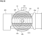
- Figs. 2 and 10 to 12 These drawings illustrate the compressor 10 and the blower fan 28 as viewed from the arrow F in Fig. 2 .
- Fig. 10 is a front view schematically illustrating the compressor 10 and the blower fan 28.
- Fig. 11 illustrates a state where a fixed scroll portion 10j is removed.
- Fig. 12 illustrates a back space 10g with an orbiting scroll portion 10h removed.
- the compressor 10 of the present embodiment is a scroll type air compressor which includes a rotary shaft 10a, a body portion 10b, a suction port 10c, a discharge port 10e, an air cooling fin 10f, an orbiting scroll portion 10h, a fixed scroll portion 10j, and a back space 10g.
- the suction port 10c communicates with the air suction part 32, and compresses the air Ar32 sucked into the pump space 10d from the air suction part 32 through the suction pipe 32b.
- the valve mechanism 32d is provided between the air suction part 32 and the suction port 10c of the compressor 10. The valve mechanism 32d opens when the compressor 10 is operated and the compressor 10 side becomes negative pressure.
- the discharge port 10e communicates with the cooler 22, and the compressed air is discharged from the discharge port 10e to the cooler 22.
- the body portion 10b is a circumferential outer peripheral wall that defines the pump space 10d.
- the body portion 10b surrounds a fixed scroll 10m and an orbiting scroll 10n in the pump space 10d.
- the fixed scroll portion 10j includes a fixed disc portion 10k provided with a plurality of air cooling fins 10f on the outside and a fixed scroll 10m fixed inside the fixed disc portion 10k.
- the discharge port 10e is provided at the center of the fixed disc portion 10k.
- the orbiting scroll portion 10h includes an orbiting disc portion 10p and an orbiting scroll 10n fixed to the orbiting disc portion 10p.
- the rotary shaft 10a extending to the input side is fixed at the center of the orbiting disc portion 10p.
- the back space 10g is provided on the input side of the orbiting disc portion 10p, that is, on the back side of the orbiting scroll portion 10h. Cooling air is introduced from the blower fan 28 into the back space 10g, and the orbiting disc portion 10p and the rotary shaft 10a are forcibly cooled by air.
- the blower fan 28 will be described later.
- the orbiting scroll 10n and the fixed scroll 10m are spiral bodies having the same shape.
- the compressor 10 compresses air when the volume of the compression space is changed by orbiting the orbiting scroll 10n integrally with the rotary shaft 10a with respect to the fixed scroll 10m.
- the compressor 10 sucks air from the outer periphery and performs compression toward the center.
- the compressor 10 may be an oil-free type.
- the blower fan 28 will be described with reference to Figs. 2 and 10 to 12 .
- the blower fan 28 is a blower mechanism that delivers cooling air (hereinafter referred to as a cooling air Ar28) to the compressor 10.
- the blower fan 28 supplies the cooling air Ar28 to the back space 10g on the back side of the orbiting scroll portion 10h to mainly cool the orbiting scroll portion 10h.
- the blower fan 28 of the present embodiment is an electric axial flow blower having a propeller 28b. As illustrated in Fig. 12 , the blower fan 28 is arranged on the side of the compressor 10 so that the rotation axis L28 of the propeller 28b is orthogonal to the rotary shaft 10a of the compressor 10. An outside air filter 28a formed of a wire mesh or the like is provided on the upstream side of the blower fan 28. A blower duct 28g for guiding the cooling air Ar28 to the central portion of the orbiting scroll portion 10h is provided on the downstream side of the blower fan 28.
- the blower duct 28g has a substantially quadrangular frustum shape of which the cross-sectional area decreases toward the compressor 10.
- the cooling air Ar28 is throttled along the inner surface of the blower duct 28g and cools the central portion of the orbiting scroll portion 10h intensively. Since the temperature of the central portion of the orbiting scroll portion 10h is the highest, the cooling effect can be enhanced by intensively cooling the center portion.
- An exhaust duct 28h is provided on the downstream side of the back space 10g. In this example, the upstream side of the exhaust duct 28h faces the blower duct 28g, and the downstream side is directed downward.
- the dehumidifier 24 is provided in a path that allows the cooler 22 and the compressed air delivery part 34 to communicate with each other.
- the dehumidifier 24 is a hollow fiber membrane type dehumidifier that dehumidifies the cooled compressed air Ar10c.
- the dehumidifier 24 may include a filter element that includes a desiccant.
- final dehumidification is performed on the compressed air Ar10d delivered from the compressed air delivery part 34.
- the compressed air Ar10d is delivered to the compressed air reservoir 92 via the compressed air delivery part 34.
- the air introduction unit 26 introduces the compressed air Ar10d dehumidified by the dehumidifier 24 into the casing 12c of the motor 12.
- the air introduction unit 26 delivers the compressed air Ar10d to the introduction port 12h provided in the bottom portion 12e.
- the air introduction unit 26 is provided with a valve mechanism 26d on a path for guiding the compressed air Ar10d from the dehumidifier 24 to the casing 12c.
- the valve mechanism 26d may be a check valve that allows the compressed air Ar10d to pass to the casing 12c side and block backflow from the casing 12c to the dehumidifier 24 when the dehumidifier 24 side is equal to or higher than a predetermined pressure.
- the bearing holder 38 will be described with reference to Figs. 2 and 3 .
- the bearing holder 38 is a portion that is provided on the input side of the compressor 10 and supports bearings 38h and 38j that rotatably support the rotary shaft 10a.
- the bearing holder 38 has a hollow cylindrical portion 38a and a plurality of fins 38f extending radially outward from the cylindrical portion 38a.
- the fin 38f has a triangular shape of which radially outer end extends radially outward as it approaches the compressor 10 in the axial direction. In this example, four fins 38f are provided at 90° intervals in the circumferential direction on the outer periphery of the cylindrical portion 38a.
- the bearing holder 38 also has a function of radiating heat generated in the compressor 10 to suppress an excessive temperature rise of the bearings 38h and 38j.
- the bearings 38h and 38j include a first bearing 38h arranged near the compressor 10 and a second bearing 38j arranged near the motor 12.
- the first and second bearings 38h and 38j rotatably support the rotary shaft 10a.
- the first and second bearings 38h and 38j are held in the hollow portion of the cylindrical portion 38a while being separated in the axial direction.
- a part of the bearing holder 38 enters the inner peripheral portion of the multiblade fan 16 in the axial direction. Further, at least a part of the bearing 38j that supports the rotary shaft 10a of the compressor 10 overlaps the multiblade fan 16 in the axial direction. In this case, the axial space can be used more effectively than the case of no overlap.
- the inverter control device 40 will be described with reference to Figs. 1 and 2 .
- the inverter control device 40 functions as an inverter power supply device for driving and controlling the motor 12.
- the inverter control device 40 is protected from dust or rainwater by being stored in the storage box 42.
- the storage box 42 may be made of metal.
- the inverter control device 40 includes electronic components (all not illustrated) such as a switching power module and a smoothing capacitor for supplying a drive current to the coil 12g.
- the storage box 42 is provided on the path of the suction air Ar32 between the air suction part 32 and the suction port 10c of the compressor 10.
- the storage box 42 is provided between the air suction part 32 and the valve mechanism 32d. That is, part or all of the suction air Ar32 passes through the storage box 42 and is delivered to the compressor 10 side.
- the suction air Ar32 passes through the storage box 42, the inside of the box is forcibly ventilated, and the electronic components of the inverter control device 40 are air-cooled. In this case, the rise of the inner temperature of the storage box 42 is suppressed, and the lifetime of the electronic component is extended.
- the housing case 36 houses the compressor 10, the compressor driving part 14, the multiblade fan 16, the cooler 22, the dehumidifier 24, the air introduction unit 26, the blower fan 28, the air suction part 32, the compressed air delivery part 34, and the storage box 42 of the inverter control device 40.
- the outline of one aspect of the present invention is as follows.
- the air compression device 100 includes: the compressor 10 that generates compressed air; the motor 12 that drives the compressor 10; the multiblade fan 16 that is driven by the motor 12 to generate an air flow; and the first cooler 18 that cools the compressed air and the second cooler 20 that cools the compressed air cooled by the first cooler 18 by the air flow.
- the first cooler 18 cools the compressed air by an air flow that has cooled the second cooler 20.
- the second cooler 20 can be reduced in size and weight. Further, by providing the first cooler 18, the input air temperature of the second cooler 20 is lowered, so that the thermal stress of the second cooler 20 is relieved.
- the first cooler 18 can effectively use the exhaust air after cooling the second cooler 20.
- the temperature difference between the cooling target air and the cooling air in the first cooler 18 is small, the thermal stress in the second cooler 20 is relieved. Further, since the temperature difference between the cooling target air and the cooling air in the second cooler 20 is large, the efficiency of heat exchange can be improved.
- the multiblade fan 16 may be arranged between the motor 12 and the compressor 10. In this case, when the multiblade fan 16 is provided on the side opposite to the compressor 10, it is necessary to provide protrusions on both the front and rear sides of the motor 12 shaft. Since the protrusions are reduced, it is possible to reduce the intrusion of dust into the motor 12 from the gaps of the protrusions.
- the first and second coolers 18 and 20 may be arranged in a direction orthogonal to the rotation axis of the multiblade fan 16. In this case, the flow path of the air flow from the multiblade fan 16 to the first and second coolers 18 and 20 is shortened, and the efficiency of the multiblade fan 16 is improved. The air flow path can be simplified.
- the first cooler 18 may be integrally arranged on the opposite side of the second cooler 20 from the multiblade fan 16. In this case, by arranging the first cooler 18 and the second cooler 20 integrally, a heat-resistant connecting hose that connects the two can be shortened or omitted.
- the air flow described above may flow around the first and second coolers 18 and 20 arranged integrally in a direction orthogonal to the rotation axis of the fan. In this case, the flow path of the air flow is shortened, the flow resistance is reduced, and the efficiency of the multiblade fan 16 is improved.
- the air flow path can be simplified.
- the air compression device 100 is an air compression device for a railway vehicle mounted under the floor of the railway vehicle 90, and the multiblade fan 16 may deliver an air flow in a direction orthogonal to the traveling direction of the railway vehicle 90.
- compressed air can be used in the vehicle 90.
- the air flow is delivered in the orthogonal direction, the flow velocity fluctuation of the air flow due to the acceleration/deceleration of the vehicle 90 can be reduced.
- it is possible to reduce dust flying from the traveling direction and entering the first and second coolers 18 and 20. The above is the description of the first embodiment.
- a second embodiment of the present invention is also an air compression device.
- the air compression device 100 includes: a front-stage cooler and a rear-stage cooler that sequentially cools compressed air generated by the compressor 10.
- the front-stage cooler includes a cooler that cools the compressed air by an air flow that has cooled the rear-stage cooler.
- the front-stage cooler may be the first cooler 18, and the rear-stage cooler may be the second cooler 20.
- the cooled compressed air may be cooled by the air flow generated by the multiblade fan 16.
- FIG. 13 is a front view illustrating the periphery of the compressor 10 and corresponds to Fig. 10 .
- the compressor 10 since the outer periphery has a negative pressure, it is easy to suck dust due to a pressure difference between the outside and the inside.
- the compressor 10 is provided with a face seal (not illustrated) that seals the outer peripheral surface.
- the face seal has a gap called a joint portion, and dust enters through this gap.
- the supercharger 210 is provided at the suction port 10c of the compressor 10.
- the supercharger 210 is not particularly limited as long as the supercharger can increase the internal pressure of the compressor 10.
- the supercharger 210 of this modification has an impeller 210b that is rotated by a motor 210m.
- the supercharger 210 pressurizes the upstream air, makes the downstream air equal to or higher than the atmospheric pressure, and supplies the air to the suction port 10c of the compressor 10.
- the supercharger 210 is provided in the path between the valve mechanism 32d and the suction port 10c.
- the coolers 18 and 20 are heat exchangers that bring the cooling air into contact with the pipe through which the cooling target air flows.
- the cooler may be based on another principle.
- the cooler may be structured to contact the cooling air with cooling fins provided on the pipe, may be structured to contact the cooling air with two metal plates sandwiching the cooling target air, or may be structured to use a double pipe.
- the output shaft 12a of the motor 12 is integrated with the rotary shaft 10a of the compressor 10, but the invention is not limited to this.
- the output shaft of the motor may be separated from the rotary shaft of the compressor and connected by a coupling or the like.
- the motor 12 which does not include a bearing and in which the stator and the rotor are built in the compressor.
- the invention is not limited to this.
- the motor may be a non-built-in structure in which a bearing, a rotor, and a stator are integrated in a motor case.
- the motor 12 is a surface magnet type DC brushless motor, but the invention is not limited to this.
- the motor may be any motor as long as the motor can drive the compressor.
- the motor may be another type of motor such as a magnet-embedded motor, an AC motor, a brushed motor, or a geared motor.
- the compressor 10 is a scroll type, but the invention is not limited to this.
- the compressor may be any compressor as long as the compressor can generate compressed air.
- the compressor may be another type of air compressor such as a screw type or a reciprocating type.
- the rotating body portion 12n of the labyrinth portion 12f also serves as the balance weight 15.
- the invention is not limited to this.
- the rotating body portion of the labyrinth portion may be provided separately from the balance weight.
- valve mechanism 26d is a check valve, but the invention is not limited to this.
- the valve mechanism 26d may be a secondary pressure adjusting valve (pressure reducing valve) capable of adjusting the pressure on the secondary side.
Abstract
Description
- The present invention relates to an air compression device.
- An air compression device is known which generates compressed air. For example,
JP 2016-075159 A - The present inventors have obtained the following recognition about the air compression device.
- The air compressed in the compressor body has a high temperature of 200°C or higher, and is preferably cooled to about room temperature when used. In the air compressor described in
JP 2016-075159 A - In order to sufficiently cool the compressor body and the aftercooler, it is conceivable to increase the size of the cooling fan. However, this case is contrary to the demand for downsizing of the air compression device on which the cooling fan is mounted. In other words, there is a tradeoff between sufficiently cooling the aftercooler and downsizing the device.
- From these, the present inventors have recognized that there is room for improvement in the viewpoint of efficiently cooling the compressed air in the air compression device.
- The present invention has been made in view of these problems, and an object of the present invention is to provide an air compression device capable of efficiently cooling air compressed by a compressor while suppressing an increase in size.
- In order to solve the above-described problems, an air compression device according to one aspect of the present invention includes: a compressor that generates compressed air; a motor that drives the compressor; a fan that is driven by the motor to generate an air flow; and a first cooler that cools the compressed air and a second cooler that cools the compressed air cooled by the first cooler by the air flow. The first cooler cools the compressed air by an air flow that has cooled the second cooler.
- In addition, the above arbitrary combinations or ones obtained by mutually replacing the constituent elements and expressions of the present invention between a method, a device, a program, a temporary or non-temporary storage medium recording the program, a system, and the like are effective as an embodiment of the present invention.
- According to this invention, the air compression device can be provided which can cool efficiently the air compressed by the compressor while suppressing an increase in size.
-
Fig. 1 is a system diagram schematically illustrating a configuration of an air compression device according to a first embodiment of the present invention; -
Fig. 2 is a schematic view illustrating a state where the air compression device ofFig. 1 is installed in a railway vehicle; -
Fig. 3 is a side sectional view schematically illustrating a periphery of a compressor driving part and a multiblade fan of the air compression device ofFig. 1 ; -
Fig. 4 is a perspective view schematically illustrating a cooler of the air compression device ofFig. 1 ; -
Fig. 5 is a schematic view for explaining the flow of air in the cooler ofFig. 4 ; -
Fig. 6 is an enlarged side sectional view illustrating a periphery of a labyrinth portion of the compressor driving part ofFig. 3 ; -
Fig. 7 is a perspective view illustrating a periphery of the multiblade fan of the air compression device ofFig. 1 ; -
Fig. 8 is a front view illustrating a periphery of a balance weight of the compressor driving part ofFig. 3 ; -
Fig. 9 is a rear view illustrating the periphery of the balance weight of the compressor driving part inFig. 3 ; -
Fig. 10 is a front view schematically illustrating a compressor and a blower fan of the air compression device ofFig. 1 ; -
Fig. 11 is another front view schematically illustrating the compressor and the blower fan of the air compression device ofFig. 1 ; -
Fig. 12 is a view schematically illustrating a flow of air from the blower fan ofFig. 10 ; and -
Fig. 13 is a front view schematically illustrating a periphery of a compressor of an air compression device according to a first modification. - Hereinafter, a preferred embodiment of the invention will be described with reference to the accompanying drawings. In an embodiment and it's modification, the same or equivalent components and members are denoted by the same reference numerals, and repeated description is appropriately omitted. In addition, the dimensions of the members in each drawing are appropriately enlarged or reduced for easy understanding. In addition, in the drawings, some of the members that are not important for describing the embodiment are omitted.
- In addition, terms including ordinal numbers such as first and second are used to describe various components. However, this term is used only for the purpose of distinguishing one component from other components, and the components are not limited by the term.
- With reference to the drawings, a configuration of an
air compression device 100 according to a first embodiment of the present invention will be described. As an example, theair compression device 100 is provided under a floor of a railway vehicle and can be used as an air compression device for a railway vehicle which supplies compressed air to the vehicle.Fig. 1 is a system diagram schematically illustrating a configuration of theair compression device 100.Fig. 2 is a schematic view illustrating a state in which theair compression device 100 is installed in therailway vehicle 90. In this drawing, for easy understanding, a part of abearing holder 38 and amultiblade fan 16 is fractured, and ablower fan 28 is shown smaller than an actual ratio. - The
air compression device 100 of the present embodiment includes acompressor 10, acompressor driving part 14, amultiblade fan 16, acooler 22, adehumidifier 24, anair introduction unit 26, ablower fan 28, anair suction part 32, a compressedair delivery part 34, aninverter control device 40, and ahousing case 36. Theair compression device 100 compresses the air sucked from theair suction part 32 with thecompressor 10, cools the air with thecooler 22, dehumidifies the air with thedehumidifier 24, delivers the air out from the compressedair delivery part 34, and supplies the air to thevehicle 90. - The
compressor 10 generates compressed air. Thecompressor driving part 14 includes amotor 12 that drives thecompressor 10. Theinverter control device 40 drives themotor 12 of thecompressor driving part 14. Themultiblade fan 16 is driven by themotor 12 to generate an air flow used for cooling by thecooler 22. Themultiblade fan 16 may be referred to as a sirocco fan. Theair introduction unit 26 introduces the compressed air into themotor 12. Theblower fan 28 generates an air flow that cools thecompressor 10. - Hereinafter, the direction along the central axis La of the
rotary shaft 10a of thecompressor 10 is referred to as "axial direction", and the circumferential direction and the radial direction of the circle centered on the central axis La are respectively "circumferential direction" and "radial direction". Hereinafter, for convenience, one side (a right side in the drawing) in the axial direction is referred to as an input side, and the other side (a left side in the drawing) is referred to as a non-input side. In this example, themotor 12 is provided on the input side of thecompressor 10, and thecompressor 10 is provided on the non-input side of themotor 12. - The
air suction part 32 is installed in thehousing case 36 and functions as a mechanism for sucking air (outside air) compressed by thecompressor 10. Theair suction part 32 is formed so as to communicate with thecompressor 10 through thesuction pipe 32b. Theair suction part 32 is provided with asuction filter 32a that suppresses the passage of dust such as sand dust when the suction air passes. Thesuction filter 32a may be a filter using a mesh. - The compressed
air delivery part 34 functions as a mechanism that delivers the compressed air Ar10d cooled by thecooler 22 described later and dehumidified by thedehumidifier 24. The compressedair delivery part 34 supplies the generated compressed air Ar10d to thecompressed air reservoir 92 installed outside thehousing case 36. The compressedair delivery part 34 may include avalve mechanism 34d provided in a path that allows thedehumidifier 24 and thecompressed air reservoir 92 to communicate with each other. Thevalve mechanism 34d may be a check valve that allows the compressed air Ar10d to pass to thecompressed air reservoir 92 side and prevent backflow from thecompressed air reservoir 92 when thedehumidifier 24 side is equal to or higher than a predetermined pressure. - The cooler 22 will be described with reference to
Figs. 2 to 5 .Fig. 3 is a side sectional view schematically illustrating the periphery of thecompressor driving part 14 and themultiblade fan 16.Fig. 4 is a perspective view schematically illustrating the cooler 22.Fig. 5 is a schematic view for explaining the flow of air in the cooler 22. The cooler 22 cools the compressed air supplied from thecompressor 10 at a high temperature (for example, 200°C to 250°C) to a temperature slightly higher than the room temperature (for example, 40°C to 50°C) and supplies the compressed air to thedehumidifier 24. - The cooler 22 of the present embodiment includes a
first cooler 18 and asecond cooler 20 that sequentially cool the compressed air generated by thecompressor 10. Thefirst cooler 18 is a front-stage cooler provided in the front stage of thesecond cooler 20, and thesecond cooler 20 is a rear-stage cooler provided in the rear stage of thefirst cooler 18. Thesecond cooler 20 may be referred to as an aftercooler, and thefirst cooler 18 may be referred to as a precooler. Thesecond cooler 20 secondarily cools the compressed air cooled by thefirst cooler 18 by the air flow Ar16a generated by themultiblade fan 16. Thefirst cooler 18 primarily cools the compressed air from thecompressor 10 by the air flow Ar16b used for cooling by thesecond cooler 20. - The
first cooler 18 and thesecond cooler 20 may be arranged anywhere as long as a desired cooling effect is obtained. Thefirst cooler 18 and thesecond cooler 20 of the present embodiment are arranged above the center of theair compression device 100 in the vertical direction. Thefirst cooler 18 and thesecond cooler 20 may be arranged in a direction orthogonal to the rotation axis of themultiblade fan 16. In particular, thefirst cooler 18 and thesecond cooler 20 are arranged above themultiblade fan 16 and between the multiblade fan and the floor of therailway vehicle 90. By shortening the path of the air flow Ar16a delivered from themultiblade fan 16, an extra piping space can be saved. Further, the longitudinal length of theair compression device 100 can be shortened compared to the case of being arranged in the longitudinal direction of themultiblade fan 16. - Although the
first cooler 18 and thesecond cooler 20 may be spaced apart from each other, in the present embodiment, thefirst cooler 18 may be arranged on the opposite side of the second cooler 20 from themultiblade fan 16. In this example, thefirst cooler 18 is laminated and integrally arranged above thesecond cooler 20. By integrally arranging the coolers, the connecting hose having heat resistance between them can be shortened or omitted. The air flow may flow around the first andsecond coolers multiblade fan 16. In this example, the air flow from themultiblade fan 16 flows from the bottom to the top through the first andsecond coolers - Detailed configurations of the
first cooler 18 and thesecond cooler 20 will be described. Thefirst cooler 18 and thesecond cooler 20 have bentpipes pipe housing parts bent pipes pipe housing parts -
Wire mesh portions bent pipes pipe housing parts pipe housing part 20c is opened, and the wire mesh portion 20n is fixed to the upper surface of thepipe housing part 18c. As described above, thepipe housing parts - The
first introduction part 18b provided at one end of thebent pipe 18p protrudes outside from the side wall of thepipe housing part 18c of thefirst cooler 18. Thefirst introduction part 18b communicates with thedischarge port 10e of thecompressor 10. A first lead-outpart 18e provided at the other end of thebent pipe 18p protrudes outside from the side wall of thepipe housing part 18c of thefirst cooler 18. The first lead-outpart 18e communicates with asecond introduction part 20b. - The
second introduction part 20b provided at one end of thebent pipe 20p protrudes outside from the bottom of thepipe housing part 20c of thesecond cooler 20. Thesecond introduction part 20b communicates with the first lead-outpart 18e by a heat-resistant connecting hose. A second lead-outpart 20e provided at the other end of thebent pipe 20p protrudes outside from the side wall of thepipe housing part 20c of thesecond cooler 20. The second lead-outpart 20e communicates with thedehumidifier 24. - The
pipe housing part 18c is arranged on the upper side of thepipe housing part 20c. The air flow Ar16a delivered from themultiblade fan 16 is supplied to the lower surface of thepipe housing part 20c through theduct 16d. The air flow Ar16a flows through the gap of thewire mesh portion 20m and the gap of thebent pipe 20p, and is discharged from the upper surface of thepipe housing part 20c. As the air flow Ar16a passes through the outer peripheral surface of thebent pipe 20p, the compressed air of thebent pipe 20p is cooled. - The air flow Ar16b discharged from the
pipe housing part 20c is supplied to the lower surface of thepipe housing part 18c. The air flow Ar16b flows through the gap of thewire mesh portion 18m, the gap of thebent pipe 18p, and the gap of the wire mesh portion 20n, and is discharged from the upper surface of thepipe housing part 18c. The compressed air Ar20c of thebent pipe 18p is cooled by the air flow Ar16b passing through the outer peripheral surface of thebent pipe 18p. The air discharged from thepipe housing part 18c is diffused into the atmosphere. - As described above, the air flow Ar16a delivered from the
multiblade fan 16 is supplied to thesecond cooler 20 first and is used for secondary cooling of the compressed air after the primary cooling. The air flow Ar16b discharged from thesecond cooler 20 is supplied to thefirst cooler 18 and is used for primary cooling of the compressed air. Compared to the case where the air flow Ar16a is used for the primary cooling first, the temperature difference between the compressed air and the cooling air in the secondary cooling becomes large, so that the cooling efficiency can be increased. - The
compressor driving part 14 will be described with reference toFigs. 2 ,3 , and6. Fig. 6 is an enlarged side sectional view illustrating the periphery of thelabyrinth portion 12f of thecompressor driving part 14. Thecompressor driving part 14 mainly includes amotor 12 that rotationally drives thecompressor 10 and abalance weight 15. - The
motor 12 will be described. Themotor 12 includes anoutput shaft 12a, arotor 12k, astator 12s, acasing 12c, and alabyrinth portion 12f. In the present embodiment, theoutput shaft 12a of themotor 12 is provided integrally with therotary shaft 10a of thecompressor 10. Therotor 12k includes amagnet 12m having a plurality of magnetic poles in the circumferential direction and is fixed to the outer periphery of theoutput shaft 12a. Therotor 12k is fixed to an input side of arotor fixing part 15d of thebalance weight 15 described later by a fastener such as a bolt (not illustrated). An adhesive may be used in combination for these fixations. - The
stator 12s includes astator core 12j that surrounds therotor 12k via a magnetic gap and acoil 12g that is wound around thestator core 12j. The outer periphery of thestator 12s is fixed to the inner peripheral surface of thecasing 12c. Thecasing 12c includes acylindrical portion 12d and abottom portion 12e, and functions as an outer shell that surrounds therotor 12k and thestator 12s. In this example, thecasing 12c has a bottomed cylindrical shape in which the non-input side is opened and thebottom portion 12e is provided on the input side. Thebottom portion 12e is provided with anintroduction port 12h for taking in air from theair introduction unit 26. - The
labyrinth portion 12f is provided so as to cover the non-input side of thecylindrical portion 12d, and has a disc shape in this example. Thelabyrinth portion 12f includes arotating body portion 12n fixed to theoutput shaft 12a and astationary body portion 12p fixed to thecylindrical portion 12d. Thestationary body portion 12p is a donut-shaped disc member in which a stationary body sidelabyrinth forming part 12q is provided on the outer periphery of the non-input side end surface. The stationary body sidelabyrinth forming part 12q includes a stationary body sideconcave portion 12t and a stationary body sideconvex portion 12u. The labyrinthconvex portion 15h described later enters the stationary body sideconcave portion 12t. The stationary body sideconvex portion 12u enters a labyrinthconcave portion 15g described later. The stationary body sideconvex portion 12u is an annular wall provided on the inner peripheral side of the stationary body sideconcave portion 12t. Therotating body portion 12n also serves as thebalance weight 15 described later. Alabyrinth 12r is provided between therotating body portion 12n and thestationary body portion 12p. In this example, thelabyrinth 12r is a maze that combines bended spaces. Thelabyrinth portion 12f includes thelabyrinth 12r to reduce the intrusion of dust into themotor 12. - Further, since the compressed air Ar10e introduced from the
introduction port 12h flows outward from thelabyrinth 12r, the dust in thelabyrinth 12r is easily discharged to the outside by this air flow. - The
motor 12 generates a field magnetic field in the magnetic gap when a drive current is provided to thecoil 12g of thestator 12s from an inverter control device 40 (drive circuit) described later. Themotor 12 generates a rotational driving force on therotor 12k and theoutput shaft 12a due to the field magnetic field and themagnet 12m of therotor 12k. The rotational driving force of theoutput shaft 12a drives themultiblade fan 16 and thecompressor 10 through therotary shaft 10a. The bearing that supports therotary shaft 10a is provided in thebearing holder 38 outside thecompressor driving part 14, and is not provided in thecompressor driving part 14. - The
multiblade fan 16 will be described with reference toFig. 3 ,6 , and7. Fig. 7 is a perspective view illustrating the periphery of themultiblade fan 16. This drawing illustrates thebalance weight 15 integrated with therotor 12k and themultiblade fan 16. Themultiblade fan 16 is arranged between thecompressor 10 and themotor 12 in the axial direction. Themultiblade fan 16 functions as a fan that rotates integrally with therotor 12k of themotor 12. In particular, themultiblade fan 16 functions as a blower that collects and sends the air flow generated from the central portion toward the outer periphery in adelivery duct 16d. Themultiblade fan 16 includes adisc portion 16b and a plurality ofblades 16c. - The
disc portion 16b is a donut-shaped disc member of which the inner peripheral side is fixed to therotary shaft 10a via abalance weight 15. In particular, thedisc portion 16b is fixed to afan fixing part 15c provided on the non-input side end surface of thebalance weight 15 with a fastener such as a bolt (not illustrated). An adhesive may be used in combination for these fixations. The plurality ofblades 16c extend from thedisc portion 16b to the non-input side in the vicinity of the outer periphery of thedisc portion 16b. The plurality ofblades 16c are arranged at predetermined angles in the circumferential direction. The plurality ofblades 16c function as an air flow generation part that generates an air flow toward the outer periphery by rotating. Thecasing 16e is a cylindrical member that surrounds thedisc portion 16b and the plurality ofblades 16c. - As illustrated in
Fig. 6 , thedisc portion 16b is arranged on the non-input side end surface of themotor 12 with theaxial gap 16g interposed therebetween. The width W16 of theaxial gap 16g may be narrower than the thickness H16 of thedisc portion 16b. As illustrated inFig. 3 , in the axial direction, theblade 16c overlaps a second bearing 13e in the axial direction. - The
delivery duct 16d is a cylindrical member extending from thecasing 16e to the cooler 22. Alower portion 16h of thedelivery duct 16d is a substantially rectangular tube-shaped portion extending upward from the upper portion of thecasing 16e. Anupper portion 16j of thedelivery duct 16d is a portion that communicates with the lower portion of the cooler 22 from the upper portion of thelower portion 16h. Theupper portion 16j has a substantially quadrangular pyramid shape with a wide upper side. - The
multiblade fan 16 may overlap with at least a part of abearing 38j that supports therotary shaft 10a of thecompressor 10 in the axial direction. In this case, the axial length of theair compression device 100 can be shortened compared to the case where themultiblade fan 16 does not overlap thebearing 38j. - The
balance weight 15 will be described with reference toFigs. 8 and9 .Fig. 8 is a front view illustrating the periphery of thebalance weight 15.Fig. 9 is a rear view illustrating the periphery of thebalance weight 15. Thebalance weight 15 also functions as an intermediate member arranged between therotor 12k and themultiblade fan 16. Thebalance weight 15 is a disc-shaped member made of metal such as brass, and also serves as therotating body portion 12n of thelabyrinth portion 12f as described above. Thebalance weight 15 includesbalance adjusting units fan fixing part 15c, arotor fixing part 15d, ashaft fastening part 15f, and alabyrinth forming part 15e. - The
fan fixing part 15c is an annular portion in which themultiblade fan 16 is fixed on the non-input side end surface. Therotor fixing part 15d is an annular portion to which therotor 12k is fixed on the input side end surface, and in this example, has a cylindrical outer shape protruding from the outer periphery to the input side. Theshaft fastening part 15f is a through hole into which theoutput shaft 12a is inserted and fixed. - The
labyrinth forming part 15e is a portion where the labyrinthconcave portion 15g and the labyrinthconvex portion 15h are provided in the outer periphery of the input side end surface. The labyrinthconcave portion 15g is an annular concave portion formed on the non-input side in thelabyrinth forming part 15e. The stationary body sideconvex portion 12u enters the labyrinthconcave portion 15g through a gap. The labyrinthconvex portion 15h is a portion that enters the stationary body sideconcave portion 12t through a gap. The labyrinthconvex portion 15h in this example is an annular wall provided so as to surround the outer peripheral side of the labyrinthconcave portion 15g. - The
balance adjusting units balance weight 15, therotor 12k, and themultiblade fan 16. That is, in a state where themultiblade fan 16 and therotor 12k are fixed and integrated with thebalance weight 15, thebalance adjusting units - The
balance adjusting units balance weight 15. However, in the present embodiment, thebalance adjusting units balance adjusting units side adjusting part 15a provided on the radially inner side from thefan fixing part 15c and a rotorside adjusting part 15b provided on the radially outer side from therotor fixing part 15d. In particular, thebalance adjusting unit 15a may be provided on the radially inner side from the air flow generation part of themultiblade fan 16. In this example, thebalance adjusting unit 15a is provided on the radially inner side from the plurality ofblades 16c. As illustrated inFigs. 8 and9 , thebalance adjusting units balance weight 15. - The
compressor 10 will be described with reference toFigs. 2 and10 to 12 . These drawings illustrate thecompressor 10 and theblower fan 28 as viewed from the arrow F inFig. 2 .Fig. 10 is a front view schematically illustrating thecompressor 10 and theblower fan 28.Fig. 11 illustrates a state where a fixedscroll portion 10j is removed.Fig. 12 illustrates aback space 10g with anorbiting scroll portion 10h removed. Thecompressor 10 of the present embodiment is a scroll type air compressor which includes arotary shaft 10a, abody portion 10b, asuction port 10c, adischarge port 10e, anair cooling fin 10f, anorbiting scroll portion 10h, a fixedscroll portion 10j, and aback space 10g. - In the
compressor 10, thesuction port 10c communicates with theair suction part 32, and compresses the air Ar32 sucked into thepump space 10d from theair suction part 32 through thesuction pipe 32b. Thevalve mechanism 32d is provided between theair suction part 32 and thesuction port 10c of thecompressor 10. Thevalve mechanism 32d opens when thecompressor 10 is operated and thecompressor 10 side becomes negative pressure. Thedischarge port 10e communicates with the cooler 22, and the compressed air is discharged from thedischarge port 10e to the cooler 22. - The
body portion 10b is a circumferential outer peripheral wall that defines thepump space 10d. Thebody portion 10b surrounds afixed scroll 10m and anorbiting scroll 10n in thepump space 10d. The fixedscroll portion 10j includes a fixeddisc portion 10k provided with a plurality ofair cooling fins 10f on the outside and afixed scroll 10m fixed inside the fixeddisc portion 10k. Thedischarge port 10e is provided at the center of the fixeddisc portion 10k. Theorbiting scroll portion 10h includes anorbiting disc portion 10p and anorbiting scroll 10n fixed to theorbiting disc portion 10p. Therotary shaft 10a extending to the input side is fixed at the center of theorbiting disc portion 10p. Theback space 10g is provided on the input side of theorbiting disc portion 10p, that is, on the back side of theorbiting scroll portion 10h. Cooling air is introduced from theblower fan 28 into theback space 10g, and theorbiting disc portion 10p and therotary shaft 10a are forcibly cooled by air. Theblower fan 28 will be described later. - The
orbiting scroll 10n and the fixedscroll 10m are spiral bodies having the same shape. Thecompressor 10 compresses air when the volume of the compression space is changed by orbiting theorbiting scroll 10n integrally with therotary shaft 10a with respect to the fixedscroll 10m. Thecompressor 10 sucks air from the outer periphery and performs compression toward the center. Thecompressor 10 may be an oil-free type. - The
blower fan 28 will be described with reference toFigs. 2 and10 to 12 . Theblower fan 28 is a blower mechanism that delivers cooling air (hereinafter referred to as a cooling air Ar28) to thecompressor 10. Theblower fan 28 supplies the cooling air Ar28 to theback space 10g on the back side of theorbiting scroll portion 10h to mainly cool theorbiting scroll portion 10h. - The
blower fan 28 of the present embodiment is an electric axial flow blower having apropeller 28b. As illustrated inFig. 12 , theblower fan 28 is arranged on the side of thecompressor 10 so that the rotation axis L28 of thepropeller 28b is orthogonal to therotary shaft 10a of thecompressor 10. Anoutside air filter 28a formed of a wire mesh or the like is provided on the upstream side of theblower fan 28. Ablower duct 28g for guiding the cooling air Ar28 to the central portion of theorbiting scroll portion 10h is provided on the downstream side of theblower fan 28. - The
blower duct 28g has a substantially quadrangular frustum shape of which the cross-sectional area decreases toward thecompressor 10. The cooling air Ar28 is throttled along the inner surface of theblower duct 28g and cools the central portion of theorbiting scroll portion 10h intensively. Since the temperature of the central portion of theorbiting scroll portion 10h is the highest, the cooling effect can be enhanced by intensively cooling the center portion. Anexhaust duct 28h is provided on the downstream side of theback space 10g. In this example, the upstream side of theexhaust duct 28h faces theblower duct 28g, and the downstream side is directed downward. - The
dehumidifier 24 is provided in a path that allows the cooler 22 and the compressedair delivery part 34 to communicate with each other. Thedehumidifier 24 is a hollow fiber membrane type dehumidifier that dehumidifies the cooled compressed air Ar10c. Thedehumidifier 24 may include a filter element that includes a desiccant. In thedehumidifier 24, final dehumidification is performed on the compressed air Ar10d delivered from the compressedair delivery part 34. The compressed air Ar10d is delivered to thecompressed air reservoir 92 via the compressedair delivery part 34. - The
air introduction unit 26 introduces the compressed air Ar10d dehumidified by thedehumidifier 24 into thecasing 12c of themotor 12. When the compressed air Ar10d is introduced to make the pressure inside thecasing 12c a positive pressure higher than the external pressure, it is possible to reduce the intrusion of dust. Theair introduction unit 26 delivers the compressed air Ar10d to theintroduction port 12h provided in thebottom portion 12e. Theair introduction unit 26 is provided with avalve mechanism 26d on a path for guiding the compressed air Ar10d from thedehumidifier 24 to thecasing 12c. Thevalve mechanism 26d may be a check valve that allows the compressed air Ar10d to pass to thecasing 12c side and block backflow from thecasing 12c to thedehumidifier 24 when thedehumidifier 24 side is equal to or higher than a predetermined pressure. - The bearing
holder 38 will be described with reference toFigs. 2 and3 . The bearingholder 38 is a portion that is provided on the input side of thecompressor 10 and supportsbearings rotary shaft 10a. The bearingholder 38 has a hollowcylindrical portion 38a and a plurality offins 38f extending radially outward from thecylindrical portion 38a. Thefin 38f has a triangular shape of which radially outer end extends radially outward as it approaches thecompressor 10 in the axial direction. In this example, fourfins 38f are provided at 90° intervals in the circumferential direction on the outer periphery of thecylindrical portion 38a. The bearingholder 38 also has a function of radiating heat generated in thecompressor 10 to suppress an excessive temperature rise of thebearings - The
bearings first bearing 38h arranged near thecompressor 10 and asecond bearing 38j arranged near themotor 12. The first andsecond bearings rotary shaft 10a. The first andsecond bearings cylindrical portion 38a while being separated in the axial direction. - A part of the bearing
holder 38 enters the inner peripheral portion of themultiblade fan 16 in the axial direction. Further, at least a part of thebearing 38j that supports therotary shaft 10a of thecompressor 10 overlaps themultiblade fan 16 in the axial direction. In this case, the axial space can be used more effectively than the case of no overlap. - The
inverter control device 40 will be described with reference toFigs. 1 and2 . Theinverter control device 40 functions as an inverter power supply device for driving and controlling themotor 12. Theinverter control device 40 is protected from dust or rainwater by being stored in thestorage box 42. Thestorage box 42 may be made of metal. Theinverter control device 40 includes electronic components (all not illustrated) such as a switching power module and a smoothing capacitor for supplying a drive current to thecoil 12g. - Since these electronic components self-heat during operation, the inner temperature of the
storage box 42 increases. When the inner temperature of the box becomes high, the lifetime of these electronic components is shortened, and may cause failure. In the present embodiment, thestorage box 42 is provided on the path of the suction air Ar32 between theair suction part 32 and thesuction port 10c of thecompressor 10. In this example, thestorage box 42 is provided between theair suction part 32 and thevalve mechanism 32d. That is, part or all of the suction air Ar32 passes through thestorage box 42 and is delivered to thecompressor 10 side. As the suction air Ar32 passes through thestorage box 42, the inside of the box is forcibly ventilated, and the electronic components of theinverter control device 40 are air-cooled. In this case, the rise of the inner temperature of thestorage box 42 is suppressed, and the lifetime of the electronic component is extended. - The
housing case 36 houses thecompressor 10, thecompressor driving part 14, themultiblade fan 16, the cooler 22, thedehumidifier 24, theair introduction unit 26, theblower fan 28, theair suction part 32, the compressedair delivery part 34, and thestorage box 42 of theinverter control device 40. - The outline of one aspect of the present invention is as follows. The
air compression device 100 according to one aspect of the present invention includes: thecompressor 10 that generates compressed air; themotor 12 that drives thecompressor 10; themultiblade fan 16 that is driven by themotor 12 to generate an air flow; and thefirst cooler 18 that cools the compressed air and thesecond cooler 20 that cools the compressed air cooled by thefirst cooler 18 by the air flow. Thefirst cooler 18 cools the compressed air by an air flow that has cooled thesecond cooler 20. - According to this aspect, by providing the
first cooler 18, thesecond cooler 20 can be reduced in size and weight. Further, by providing thefirst cooler 18, the input air temperature of thesecond cooler 20 is lowered, so that the thermal stress of thesecond cooler 20 is relieved. - Further, the
first cooler 18 can effectively use the exhaust air after cooling thesecond cooler 20. In addition, since the temperature difference between the cooling target air and the cooling air in thefirst cooler 18 is small, the thermal stress in thesecond cooler 20 is relieved. Further, since the temperature difference between the cooling target air and the cooling air in thesecond cooler 20 is large, the efficiency of heat exchange can be improved. - The
multiblade fan 16 may be arranged between themotor 12 and thecompressor 10. In this case, when themultiblade fan 16 is provided on the side opposite to thecompressor 10, it is necessary to provide protrusions on both the front and rear sides of themotor 12 shaft. Since the protrusions are reduced, it is possible to reduce the intrusion of dust into themotor 12 from the gaps of the protrusions. - The first and
second coolers multiblade fan 16. In this case, the flow path of the air flow from themultiblade fan 16 to the first andsecond coolers multiblade fan 16 is improved. The air flow path can be simplified. - The
first cooler 18 may be integrally arranged on the opposite side of the second cooler 20 from themultiblade fan 16. In this case, by arranging thefirst cooler 18 and thesecond cooler 20 integrally, a heat-resistant connecting hose that connects the two can be shortened or omitted. - The air flow described above may flow around the first and
second coolers multiblade fan 16 is improved. The air flow path can be simplified. - The
air compression device 100 is an air compression device for a railway vehicle mounted under the floor of therailway vehicle 90, and themultiblade fan 16 may deliver an air flow in a direction orthogonal to the traveling direction of therailway vehicle 90. In this case, compressed air can be used in thevehicle 90. Further, since the air flow is delivered in the orthogonal direction, the flow velocity fluctuation of the air flow due to the acceleration/deceleration of thevehicle 90 can be reduced. Further, when thevehicle 90 travels, it is possible to reduce dust flying from the traveling direction and entering the first andsecond coolers
The above is the description of the first embodiment. - A second embodiment of the present invention is also an air compression device. The
air compression device 100 includes: a front-stage cooler and a rear-stage cooler that sequentially cools compressed air generated by thecompressor 10. The front-stage cooler includes a cooler that cools the compressed air by an air flow that has cooled the rear-stage cooler. For example, the front-stage cooler may be thefirst cooler 18, and the rear-stage cooler may be thesecond cooler 20. The cooled compressed air may be cooled by the air flow generated by themultiblade fan 16. - According to the second embodiment, the same operations and effects as in the first embodiment are achieved.
- In the above, the example of embodiment of this invention was described in detail. Each of the above-described embodiments is merely a specific example for carrying out the present invention. The contents of the embodiments do not limit the technical scope of the present invention, and many design changes such as changes, additions, and deletions of constituent elements are possible without departing from the spirit of the invention defined in the claims. In the above-described embodiments, the contents that allow such a design change have been described with the notation of "of embodiment", "in the embodiment", or the like. However, design changes are not unacceptable for content without such notation.
- Hereinafter, modifications will be described. In the drawings and descriptions of the modifications, the same reference numerals are given to the same or equivalent components and members as those in the embodiment. The description overlapping with the embodiment will be omitted as appropriate, and the configuration different from the first embodiment will be mainly described.
- With reference to
Fig. 13 , anair compression device 200 according to a first modification will be described. This modification is different from the embodiment in that asupercharger 210 is provided at the suction port of thecompressor 10 and is the same in the other configuration. Thus, thesupercharger 210 will be described mainly.Fig. 13 is a front view illustrating the periphery of thecompressor 10 and corresponds toFig. 10 . - In the scroll compressor, since the outer periphery has a negative pressure, it is easy to suck dust due to a pressure difference between the outside and the inside. In order to reduce the intrusion of dust, the
compressor 10 is provided with a face seal (not illustrated) that seals the outer peripheral surface. However, the face seal has a gap called a joint portion, and dust enters through this gap. For this reason, in this modification, thesupercharger 210 is provided at thesuction port 10c of thecompressor 10. - The
supercharger 210 is not particularly limited as long as the supercharger can increase the internal pressure of thecompressor 10. Thesupercharger 210 of this modification has animpeller 210b that is rotated by amotor 210m. Thesupercharger 210 pressurizes the upstream air, makes the downstream air equal to or higher than the atmospheric pressure, and supplies the air to thesuction port 10c of thecompressor 10. Thesupercharger 210 is provided in the path between thevalve mechanism 32d and thesuction port 10c. By providing thesupercharger 210, it is possible to increase the internal pressure in the vicinity of thesuction port 10c of thecompressor 10, that is, the outer periphery of thecompressor 10, and to suppress the intrusion of dust due to negative pressure. - In the description of the embodiment, the
coolers - In the description of the embodiment, an example is described in which the
output shaft 12a of themotor 12 is integrated with therotary shaft 10a of thecompressor 10, but the invention is not limited to this. For example, the output shaft of the motor may be separated from the rotary shaft of the compressor and connected by a coupling or the like. - In the description of the embodiment, the
motor 12 is described which does not include a bearing and in which the stator and the rotor are built in the compressor. However, the invention is not limited to this. For example, the motor may be a non-built-in structure in which a bearing, a rotor, and a stator are integrated in a motor case. - In the description of the embodiment, an example is described in which the
motor 12 is a surface magnet type DC brushless motor, but the invention is not limited to this. The motor may be any motor as long as the motor can drive the compressor. For example, the motor may be another type of motor such as a magnet-embedded motor, an AC motor, a brushed motor, or a geared motor. - In the description of the embodiment, an example is described in which the
compressor 10 is a scroll type, but the invention is not limited to this. The compressor may be any compressor as long as the compressor can generate compressed air. For example, the compressor may be another type of air compressor such as a screw type or a reciprocating type. - In the description of the embodiment, an example is described in which the
rotating body portion 12n of thelabyrinth portion 12f also serves as thebalance weight 15. However, the invention is not limited to this. The rotating body portion of the labyrinth portion may be provided separately from the balance weight. - In the description of the embodiment, an example is described in which the
valve mechanism 26d is a check valve, but the invention is not limited to this. For example, thevalve mechanism 26d may be a secondary pressure adjusting valve (pressure reducing valve) capable of adjusting the pressure on the secondary side. - The above-described modification has the same operations and effects as those of the first embodiment.
- Any combination of the above-described embodiments and modifications is also useful as an embodiment of the present invention. The new embodiment made by the combination has the effects of the combined embodiment and modifications.
Claims (6)
- An air compression device (100) comprising:a compressor (10) that generates compressed air;a motor (12) that drives the compressor;a fan (16) that is driven by the motor to generate an air flow; anda first cooler (8) that cools the compressed air and a second cooler (20) that cools the compressed air cooled by the first cooler by the air flow, whereinthe first cooler cools the compressed air by an air flow that has cooled the second cooler.
- The air compression device according to claim 1, wherein
the fan is arranged between the motor and the compressor. - The air compression device according to claim 1 or 2, wherein
the first and second coolers are arranged in a direction orthogonal to a rotation axis of the fan. - The air compression device according to claim 3, wherein
the first cooler is integrally arranged on a side of the second cooler opposite to the fan. - The air compression device according to claim 4, wherein
the air flow flows around the first and second coolers arranged integrally in a direction orthogonal to the rotation axis of the fan. - An air compression device comprising:a front-stage cooler (18) and a rear-stage cooler (20) that sequentially cools compressed air generated by a compressor, whereinthe front-stage cooler includes a cooler that cools the compressed air by an air flow that has cooled the rear-stage cooler.
Applications Claiming Priority (1)
| Application Number | Priority Date | Filing Date | Title |
|---|---|---|---|
| JP2019023063A JP2020133405A (en) | 2019-02-12 | 2019-02-12 | Air compression apparatus |
Publications (2)
| Publication Number | Publication Date |
|---|---|
| EP3696421A1 true EP3696421A1 (en) | 2020-08-19 |
| EP3696421B1 EP3696421B1 (en) | 2023-05-10 |
Family
ID=69581875
Family Applications (1)
| Application Number | Title | Priority Date | Filing Date |
|---|---|---|---|
| EP20156897.9A Active EP3696421B1 (en) | 2019-02-12 | 2020-02-12 | Air compression device |
Country Status (3)
| Country | Link |
|---|---|
| EP (1) | EP3696421B1 (en) |
| JP (1) | JP2020133405A (en) |
| CN (1) | CN111550408A (en) |
Citations (5)
| Publication number | Priority date | Publication date | Assignee | Title |
|---|---|---|---|---|
| GB525964A (en) * | 1938-03-18 | 1940-09-09 | Demag Ag | Improvements relating to rotary compressors |
| US5447422A (en) * | 1991-11-08 | 1995-09-05 | Hitachi, Ltd. | Air-cooled oil-free rotary-type compressor |
| WO2002018789A1 (en) * | 2000-08-31 | 2002-03-07 | Atlas Copco Airpower, Naamloze Vennootschap | Method for regulating the temperature of the exiting compressed gas of a compressor and compressor used therewith |
| US20150329125A1 (en) * | 2014-05-15 | 2015-11-19 | Nabtesco Corporation | Air compressor unit for vehicle |
| JP2016075159A (en) | 2014-10-02 | 2016-05-12 | 株式会社日立産機システム | Package type compressor |
Family Cites Families (10)
| Publication number | Priority date | Publication date | Assignee | Title |
|---|---|---|---|---|
| JP2796342B2 (en) * | 1989-04-05 | 1998-09-10 | 株式会社日立製作所 | Dry compressed air supply device |
| JP3888095B2 (en) * | 2001-07-26 | 2007-02-28 | 株式会社日立製作所 | Gas turbine equipment |
| JP3773443B2 (en) * | 2001-12-17 | 2006-05-10 | 株式会社神戸製鋼所 | Packaged oil-cooled compressor |
| JP5385589B2 (en) * | 2008-10-30 | 2014-01-08 | シャープ株式会社 | Air conditioner outdoor unit |
| KR200446520Y1 (en) * | 2009-06-22 | 2009-11-05 | 강일중 | Air Compressing System |
| KR20110055840A (en) * | 2009-11-20 | 2011-05-26 | 삼성전자주식회사 | Air conditioner and outdoor unit thereof |
| CN201851363U (en) * | 2010-11-19 | 2011-06-01 | 南车资阳机车有限公司 | Large-ejection screw air compressor |
| JP6419456B2 (en) * | 2014-05-15 | 2018-11-07 | ナブテスコ株式会社 | Air compressor for vehicle |
| BE1022138B1 (en) * | 2014-05-16 | 2016-02-19 | Atlas Copco Airpower, Naamloze Vennootschap | COMPRESSOR DEVICE AND A COOLER THAT IS APPLIED THEREOF |
| JP6371139B2 (en) * | 2014-07-01 | 2018-08-08 | 株式会社神戸製鋼所 | Switching method |
-
2019
- 2019-02-12 JP JP2019023063A patent/JP2020133405A/en active Pending
-
2020
- 2020-02-12 EP EP20156897.9A patent/EP3696421B1/en active Active
- 2020-02-12 CN CN202010094185.2A patent/CN111550408A/en active Pending
Patent Citations (5)
| Publication number | Priority date | Publication date | Assignee | Title |
|---|---|---|---|---|
| GB525964A (en) * | 1938-03-18 | 1940-09-09 | Demag Ag | Improvements relating to rotary compressors |
| US5447422A (en) * | 1991-11-08 | 1995-09-05 | Hitachi, Ltd. | Air-cooled oil-free rotary-type compressor |
| WO2002018789A1 (en) * | 2000-08-31 | 2002-03-07 | Atlas Copco Airpower, Naamloze Vennootschap | Method for regulating the temperature of the exiting compressed gas of a compressor and compressor used therewith |
| US20150329125A1 (en) * | 2014-05-15 | 2015-11-19 | Nabtesco Corporation | Air compressor unit for vehicle |
| JP2016075159A (en) | 2014-10-02 | 2016-05-12 | 株式会社日立産機システム | Package type compressor |
Also Published As
| Publication number | Publication date |
|---|---|
| CN111550408A (en) | 2020-08-18 |
| JP2020133405A (en) | 2020-08-31 |
| EP3696421B1 (en) | 2023-05-10 |
Similar Documents
| Publication | Publication Date | Title |
|---|---|---|
| JP6382672B2 (en) | Package type compressor | |
| KR101777089B1 (en) | Air compressor unit for vehicle | |
| JP7113177B2 (en) | Temperature conditioning unit, temperature conditioning system and vehicle | |
| JP6931774B2 (en) | Temperature control system, vehicle | |
| KR102331134B1 (en) | Turbo blower with flow control cooling system | |
| JP3831736B2 (en) | Air refrigerant cooling system using an air refrigerant cooling device and an air refrigerant cooling device | |
| JP6678302B2 (en) | Temperature control unit, temperature control system, vehicle | |
| EP3696421A1 (en) | Air compression device | |
| JPH11336696A (en) | Electric blower | |
| JP2020070953A (en) | Cooling system | |
| JP2004274800A (en) | Cooling mechanism of electric motor | |
| CN109477486B (en) | Motor integrated type fluid machine | |
| EP3696415A1 (en) | Air compression device and dust prevention method for motor | |
| EP3696409A1 (en) | Air compression device | |
| EP3696411A1 (en) | Air compression device and method for manufacturing air compression device | |
| JP5389191B2 (en) | Blower and air conditioner equipped with this blower | |
| JP2009257110A (en) | Packaged air-cooled screw compressor | |
| JP2016044868A (en) | Outdoor equipment and air conditioner including the same | |
| JP7153834B2 (en) | Temperature conditioning unit | |
| JP2008136321A (en) | Rotary electric machine | |
| JP2018173050A (en) | Scroll fluid machine | |
| JP2007023958A (en) | Vane rotary type air pump | |
| KR100388554B1 (en) | Turbo compressor | |
| KR20010073551A (en) | Structure for cooling motor and shaft in turbo compressor | |
| CN115628219A (en) | Self-cooled high-speed centrifugal compressor |
Legal Events
| Date | Code | Title | Description |
|---|---|---|---|
| PUAI | Public reference made under article 153(3) epc to a published international application that has entered the european phase |
Free format text: ORIGINAL CODE: 0009012 |
|
| STAA | Information on the status of an ep patent application or granted ep patent |
Free format text: STATUS: REQUEST FOR EXAMINATION WAS MADE |
|
| 17P | Request for examination filed |
Effective date: 20200212 |
|
| AK | Designated contracting states |
Kind code of ref document: A1 Designated state(s): AL AT BE BG CH CY CZ DE DK EE ES FI FR GB GR HR HU IE IS IT LI LT LU LV MC MK MT NL NO PL PT RO RS SE SI SK SM TR |
|
| AX | Request for extension of the european patent |
Extension state: BA ME |
|
| RBV | Designated contracting states (corrected) |
Designated state(s): AL AT BE BG CH CY CZ DE DK EE ES FI FR GB GR HR HU IE IS IT LI LT LU LV MC MK MT NL NO PL PT RO RS SE SI SK SM TR |
|
| RIC1 | Information provided on ipc code assigned before grant |
Ipc: F04B 39/06 20060101ALI20220826BHEP Ipc: F04C 29/04 20060101AFI20220826BHEP |
|
| GRAP | Despatch of communication of intention to grant a patent |
Free format text: ORIGINAL CODE: EPIDOSNIGR1 |
|
| STAA | Information on the status of an ep patent application or granted ep patent |
Free format text: STATUS: GRANT OF PATENT IS INTENDED |
|
| INTG | Intention to grant announced |
Effective date: 20221130 |
|
| GRAS | Grant fee paid |
Free format text: ORIGINAL CODE: EPIDOSNIGR3 |
|
| GRAA | (expected) grant |
Free format text: ORIGINAL CODE: 0009210 |
|
| STAA | Information on the status of an ep patent application or granted ep patent |
Free format text: STATUS: THE PATENT HAS BEEN GRANTED |
|
| AK | Designated contracting states |
Kind code of ref document: B1 Designated state(s): AL AT BE BG CH CY CZ DE DK EE ES FI FR GB GR HR HU IE IS IT LI LT LU LV MC MK MT NL NO PL PT RO RS SE SI SK SM TR |
|
| REG | Reference to a national code |
Ref country code: GB Ref legal event code: FG4D |
|
| REG | Reference to a national code |
Ref country code: AT Ref legal event code: REF Ref document number: 1566918 Country of ref document: AT Kind code of ref document: T Effective date: 20230515 Ref country code: CH Ref legal event code: EP |
|
| REG | Reference to a national code |
Ref country code: DE Ref legal event code: R096 Ref document number: 602020010568 Country of ref document: DE |
|
| REG | Reference to a national code |
Ref country code: IE Ref legal event code: FG4D |
|
| P01 | Opt-out of the competence of the unified patent court (upc) registered |
Effective date: 20230413 |
|
| REG | Reference to a national code |
Ref country code: LT Ref legal event code: MG9D |
|
| REG | Reference to a national code |
Ref country code: NL Ref legal event code: MP Effective date: 20230510 |
|
| REG | Reference to a national code |
Ref country code: AT Ref legal event code: MK05 Ref document number: 1566918 Country of ref document: AT Kind code of ref document: T Effective date: 20230510 |
|
| PG25 | Lapsed in a contracting state [announced via postgrant information from national office to epo] |
Ref country code: SE Free format text: LAPSE BECAUSE OF FAILURE TO SUBMIT A TRANSLATION OF THE DESCRIPTION OR TO PAY THE FEE WITHIN THE PRESCRIBED TIME-LIMIT Effective date: 20230510 Ref country code: PT Free format text: LAPSE BECAUSE OF FAILURE TO SUBMIT A TRANSLATION OF THE DESCRIPTION OR TO PAY THE FEE WITHIN THE PRESCRIBED TIME-LIMIT Effective date: 20230911 Ref country code: NO Free format text: LAPSE BECAUSE OF FAILURE TO SUBMIT A TRANSLATION OF THE DESCRIPTION OR TO PAY THE FEE WITHIN THE PRESCRIBED TIME-LIMIT Effective date: 20230810 Ref country code: NL Free format text: LAPSE BECAUSE OF FAILURE TO SUBMIT A TRANSLATION OF THE DESCRIPTION OR TO PAY THE FEE WITHIN THE PRESCRIBED TIME-LIMIT Effective date: 20230510 Ref country code: ES Free format text: LAPSE BECAUSE OF FAILURE TO SUBMIT A TRANSLATION OF THE DESCRIPTION OR TO PAY THE FEE WITHIN THE PRESCRIBED TIME-LIMIT Effective date: 20230510 Ref country code: AT Free format text: LAPSE BECAUSE OF FAILURE TO SUBMIT A TRANSLATION OF THE DESCRIPTION OR TO PAY THE FEE WITHIN THE PRESCRIBED TIME-LIMIT Effective date: 20230510 |
|
| PG25 | Lapsed in a contracting state [announced via postgrant information from national office to epo] |
Ref country code: RS Free format text: LAPSE BECAUSE OF FAILURE TO SUBMIT A TRANSLATION OF THE DESCRIPTION OR TO PAY THE FEE WITHIN THE PRESCRIBED TIME-LIMIT Effective date: 20230510 Ref country code: PL Free format text: LAPSE BECAUSE OF FAILURE TO SUBMIT A TRANSLATION OF THE DESCRIPTION OR TO PAY THE FEE WITHIN THE PRESCRIBED TIME-LIMIT Effective date: 20230510 Ref country code: LV Free format text: LAPSE BECAUSE OF FAILURE TO SUBMIT A TRANSLATION OF THE DESCRIPTION OR TO PAY THE FEE WITHIN THE PRESCRIBED TIME-LIMIT Effective date: 20230510 Ref country code: LT Free format text: LAPSE BECAUSE OF FAILURE TO SUBMIT A TRANSLATION OF THE DESCRIPTION OR TO PAY THE FEE WITHIN THE PRESCRIBED TIME-LIMIT Effective date: 20230510 Ref country code: IS Free format text: LAPSE BECAUSE OF FAILURE TO SUBMIT A TRANSLATION OF THE DESCRIPTION OR TO PAY THE FEE WITHIN THE PRESCRIBED TIME-LIMIT Effective date: 20230910 Ref country code: HR Free format text: LAPSE BECAUSE OF FAILURE TO SUBMIT A TRANSLATION OF THE DESCRIPTION OR TO PAY THE FEE WITHIN THE PRESCRIBED TIME-LIMIT Effective date: 20230510 Ref country code: GR Free format text: LAPSE BECAUSE OF FAILURE TO SUBMIT A TRANSLATION OF THE DESCRIPTION OR TO PAY THE FEE WITHIN THE PRESCRIBED TIME-LIMIT Effective date: 20230811 |
|
| PG25 | Lapsed in a contracting state [announced via postgrant information from national office to epo] |
Ref country code: FI Free format text: LAPSE BECAUSE OF FAILURE TO SUBMIT A TRANSLATION OF THE DESCRIPTION OR TO PAY THE FEE WITHIN THE PRESCRIBED TIME-LIMIT Effective date: 20230510 |
|
| PG25 | Lapsed in a contracting state [announced via postgrant information from national office to epo] |
Ref country code: SK Free format text: LAPSE BECAUSE OF FAILURE TO SUBMIT A TRANSLATION OF THE DESCRIPTION OR TO PAY THE FEE WITHIN THE PRESCRIBED TIME-LIMIT Effective date: 20230510 |
|
| PG25 | Lapsed in a contracting state [announced via postgrant information from national office to epo] |
Ref country code: SM Free format text: LAPSE BECAUSE OF FAILURE TO SUBMIT A TRANSLATION OF THE DESCRIPTION OR TO PAY THE FEE WITHIN THE PRESCRIBED TIME-LIMIT Effective date: 20230510 Ref country code: SK Free format text: LAPSE BECAUSE OF FAILURE TO SUBMIT A TRANSLATION OF THE DESCRIPTION OR TO PAY THE FEE WITHIN THE PRESCRIBED TIME-LIMIT Effective date: 20230510 Ref country code: RO Free format text: LAPSE BECAUSE OF FAILURE TO SUBMIT A TRANSLATION OF THE DESCRIPTION OR TO PAY THE FEE WITHIN THE PRESCRIBED TIME-LIMIT Effective date: 20230510 Ref country code: EE Free format text: LAPSE BECAUSE OF FAILURE TO SUBMIT A TRANSLATION OF THE DESCRIPTION OR TO PAY THE FEE WITHIN THE PRESCRIBED TIME-LIMIT Effective date: 20230510 Ref country code: DK Free format text: LAPSE BECAUSE OF FAILURE TO SUBMIT A TRANSLATION OF THE DESCRIPTION OR TO PAY THE FEE WITHIN THE PRESCRIBED TIME-LIMIT Effective date: 20230510 Ref country code: CZ Free format text: LAPSE BECAUSE OF FAILURE TO SUBMIT A TRANSLATION OF THE DESCRIPTION OR TO PAY THE FEE WITHIN THE PRESCRIBED TIME-LIMIT Effective date: 20230510 |
|
| REG | Reference to a national code |
Ref country code: DE Ref legal event code: R097 Ref document number: 602020010568 Country of ref document: DE |
|
| PLBE | No opposition filed within time limit |
Free format text: ORIGINAL CODE: 0009261 |
|
| STAA | Information on the status of an ep patent application or granted ep patent |
Free format text: STATUS: NO OPPOSITION FILED WITHIN TIME LIMIT |
|
| 26N | No opposition filed |
Effective date: 20240213 |