EP3696378A1 - Turbine and brayton cycle including same - Google Patents
Turbine and brayton cycle including same Download PDFInfo
- Publication number
- EP3696378A1 EP3696378A1 EP19208791.4A EP19208791A EP3696378A1 EP 3696378 A1 EP3696378 A1 EP 3696378A1 EP 19208791 A EP19208791 A EP 19208791A EP 3696378 A1 EP3696378 A1 EP 3696378A1
- Authority
- EP
- European Patent Office
- Prior art keywords
- working medium
- blade
- turbine
- cooling
- heat
- Prior art date
- Legal status (The legal status is an assumption and is not a legal conclusion. Google has not performed a legal analysis and makes no representation as to the accuracy of the status listed.)
- Granted
Links
Images


Classifications
-
- F—MECHANICAL ENGINEERING; LIGHTING; HEATING; WEAPONS; BLASTING
- F01—MACHINES OR ENGINES IN GENERAL; ENGINE PLANTS IN GENERAL; STEAM ENGINES
- F01D—NON-POSITIVE DISPLACEMENT MACHINES OR ENGINES, e.g. STEAM TURBINES
- F01D5/00—Blades; Blade-carrying members; Heating, heat-insulating, cooling or antivibration means on the blades or the members
- F01D5/12—Blades
- F01D5/28—Selecting particular materials; Particular measures relating thereto; Measures against erosion or corrosion
- F01D5/288—Protective coatings for blades
-
- F—MECHANICAL ENGINEERING; LIGHTING; HEATING; WEAPONS; BLASTING
- F01—MACHINES OR ENGINES IN GENERAL; ENGINE PLANTS IN GENERAL; STEAM ENGINES
- F01D—NON-POSITIVE DISPLACEMENT MACHINES OR ENGINES, e.g. STEAM TURBINES
- F01D15/00—Adaptations of machines or engines for special use; Combinations of engines with devices driven thereby
- F01D15/10—Adaptations for driving, or combinations with, electric generators
-
- F—MECHANICAL ENGINEERING; LIGHTING; HEATING; WEAPONS; BLASTING
- F01—MACHINES OR ENGINES IN GENERAL; ENGINE PLANTS IN GENERAL; STEAM ENGINES
- F01D—NON-POSITIVE DISPLACEMENT MACHINES OR ENGINES, e.g. STEAM TURBINES
- F01D5/00—Blades; Blade-carrying members; Heating, heat-insulating, cooling or antivibration means on the blades or the members
- F01D5/12—Blades
- F01D5/14—Form or construction
- F01D5/18—Hollow blades, i.e. blades with cooling or heating channels or cavities; Heating, heat-insulating or cooling means on blades
- F01D5/186—Film cooling
-
- F—MECHANICAL ENGINEERING; LIGHTING; HEATING; WEAPONS; BLASTING
- F01—MACHINES OR ENGINES IN GENERAL; ENGINE PLANTS IN GENERAL; STEAM ENGINES
- F01D—NON-POSITIVE DISPLACEMENT MACHINES OR ENGINES, e.g. STEAM TURBINES
- F01D5/00—Blades; Blade-carrying members; Heating, heat-insulating, cooling or antivibration means on the blades or the members
- F01D5/12—Blades
- F01D5/28—Selecting particular materials; Particular measures relating thereto; Measures against erosion or corrosion
-
- F—MECHANICAL ENGINEERING; LIGHTING; HEATING; WEAPONS; BLASTING
- F01—MACHINES OR ENGINES IN GENERAL; ENGINE PLANTS IN GENERAL; STEAM ENGINES
- F01K—STEAM ENGINE PLANTS; STEAM ACCUMULATORS; ENGINE PLANTS NOT OTHERWISE PROVIDED FOR; ENGINES USING SPECIAL WORKING FLUIDS OR CYCLES
- F01K7/00—Steam engine plants characterised by the use of specific types of engine; Plants or engines characterised by their use of special steam systems, cycles or processes; Control means specially adapted for such systems, cycles or processes; Use of withdrawn or exhaust steam for feed-water heating
- F01K7/34—Steam engine plants characterised by the use of specific types of engine; Plants or engines characterised by their use of special steam systems, cycles or processes; Control means specially adapted for such systems, cycles or processes; Use of withdrawn or exhaust steam for feed-water heating the engines being of extraction or non-condensing type; Use of steam for feed-water heating
- F01K7/38—Steam engine plants characterised by the use of specific types of engine; Plants or engines characterised by their use of special steam systems, cycles or processes; Control means specially adapted for such systems, cycles or processes; Use of withdrawn or exhaust steam for feed-water heating the engines being of extraction or non-condensing type; Use of steam for feed-water heating the engines being of turbine type
-
- F—MECHANICAL ENGINEERING; LIGHTING; HEATING; WEAPONS; BLASTING
- F02—COMBUSTION ENGINES; HOT-GAS OR COMBUSTION-PRODUCT ENGINE PLANTS
- F02C—GAS-TURBINE PLANTS; AIR INTAKES FOR JET-PROPULSION PLANTS; CONTROLLING FUEL SUPPLY IN AIR-BREATHING JET-PROPULSION PLANTS
- F02C1/00—Gas-turbine plants characterised by the use of hot gases or unheated pressurised gases, as the working fluid
- F02C1/04—Gas-turbine plants characterised by the use of hot gases or unheated pressurised gases, as the working fluid the working fluid being heated indirectly
- F02C1/05—Gas-turbine plants characterised by the use of hot gases or unheated pressurised gases, as the working fluid the working fluid being heated indirectly characterised by the type or source of heat, e.g. using nuclear or solar energy
-
- F—MECHANICAL ENGINEERING; LIGHTING; HEATING; WEAPONS; BLASTING
- F03—MACHINES OR ENGINES FOR LIQUIDS; WIND, SPRING, OR WEIGHT MOTORS; PRODUCING MECHANICAL POWER OR A REACTIVE PROPULSIVE THRUST, NOT OTHERWISE PROVIDED FOR
- F03G—SPRING, WEIGHT, INERTIA OR LIKE MOTORS; MECHANICAL-POWER PRODUCING DEVICES OR MECHANISMS, NOT OTHERWISE PROVIDED FOR OR USING ENERGY SOURCES NOT OTHERWISE PROVIDED FOR
- F03G6/00—Devices for producing mechanical power from solar energy
- F03G6/06—Devices for producing mechanical power from solar energy with solar energy concentrating means
-
- F—MECHANICAL ENGINEERING; LIGHTING; HEATING; WEAPONS; BLASTING
- F01—MACHINES OR ENGINES IN GENERAL; ENGINE PLANTS IN GENERAL; STEAM ENGINES
- F01K—STEAM ENGINE PLANTS; STEAM ACCUMULATORS; ENGINE PLANTS NOT OTHERWISE PROVIDED FOR; ENGINES USING SPECIAL WORKING FLUIDS OR CYCLES
- F01K25/00—Plants or engines characterised by use of special working fluids, not otherwise provided for; Plants operating in closed cycles and not otherwise provided for
- F01K25/08—Plants or engines characterised by use of special working fluids, not otherwise provided for; Plants operating in closed cycles and not otherwise provided for using special vapours
- F01K25/10—Plants or engines characterised by use of special working fluids, not otherwise provided for; Plants operating in closed cycles and not otherwise provided for using special vapours the vapours being cold, e.g. ammonia, carbon dioxide, ether
- F01K25/103—Carbon dioxide
-
- F—MECHANICAL ENGINEERING; LIGHTING; HEATING; WEAPONS; BLASTING
- F03—MACHINES OR ENGINES FOR LIQUIDS; WIND, SPRING, OR WEIGHT MOTORS; PRODUCING MECHANICAL POWER OR A REACTIVE PROPULSIVE THRUST, NOT OTHERWISE PROVIDED FOR
- F03G—SPRING, WEIGHT, INERTIA OR LIKE MOTORS; MECHANICAL-POWER PRODUCING DEVICES OR MECHANISMS, NOT OTHERWISE PROVIDED FOR OR USING ENERGY SOURCES NOT OTHERWISE PROVIDED FOR
- F03G6/00—Devices for producing mechanical power from solar energy
- F03G6/06—Devices for producing mechanical power from solar energy with solar energy concentrating means
- F03G6/063—Tower concentrators
-
- F—MECHANICAL ENGINEERING; LIGHTING; HEATING; WEAPONS; BLASTING
- F03—MACHINES OR ENGINES FOR LIQUIDS; WIND, SPRING, OR WEIGHT MOTORS; PRODUCING MECHANICAL POWER OR A REACTIVE PROPULSIVE THRUST, NOT OTHERWISE PROVIDED FOR
- F03G—SPRING, WEIGHT, INERTIA OR LIKE MOTORS; MECHANICAL-POWER PRODUCING DEVICES OR MECHANISMS, NOT OTHERWISE PROVIDED FOR OR USING ENERGY SOURCES NOT OTHERWISE PROVIDED FOR
- F03G6/00—Devices for producing mechanical power from solar energy
- F03G6/06—Devices for producing mechanical power from solar energy with solar energy concentrating means
- F03G6/064—Devices for producing mechanical power from solar energy with solar energy concentrating means having a gas turbine cycle, i.e. compressor and gas turbine combination
-
- F—MECHANICAL ENGINEERING; LIGHTING; HEATING; WEAPONS; BLASTING
- F05—INDEXING SCHEMES RELATING TO ENGINES OR PUMPS IN VARIOUS SUBCLASSES OF CLASSES F01-F04
- F05D—INDEXING SCHEME FOR ASPECTS RELATING TO NON-POSITIVE-DISPLACEMENT MACHINES OR ENGINES, GAS-TURBINES OR JET-PROPULSION PLANTS
- F05D2260/00—Function
- F05D2260/20—Heat transfer, e.g. cooling
- F05D2260/202—Heat transfer, e.g. cooling by film cooling
-
- F—MECHANICAL ENGINEERING; LIGHTING; HEATING; WEAPONS; BLASTING
- F05—INDEXING SCHEMES RELATING TO ENGINES OR PUMPS IN VARIOUS SUBCLASSES OF CLASSES F01-F04
- F05D—INDEXING SCHEME FOR ASPECTS RELATING TO NON-POSITIVE-DISPLACEMENT MACHINES OR ENGINES, GAS-TURBINES OR JET-PROPULSION PLANTS
- F05D2260/00—Function
- F05D2260/20—Heat transfer, e.g. cooling
- F05D2260/221—Improvement of heat transfer
-
- F—MECHANICAL ENGINEERING; LIGHTING; HEATING; WEAPONS; BLASTING
- F05—INDEXING SCHEMES RELATING TO ENGINES OR PUMPS IN VARIOUS SUBCLASSES OF CLASSES F01-F04
- F05D—INDEXING SCHEME FOR ASPECTS RELATING TO NON-POSITIVE-DISPLACEMENT MACHINES OR ENGINES, GAS-TURBINES OR JET-PROPULSION PLANTS
- F05D2300/00—Materials; Properties thereof
- F05D2300/60—Properties or characteristics given to material by treatment or manufacturing
- F05D2300/611—Coating
-
- F—MECHANICAL ENGINEERING; LIGHTING; HEATING; WEAPONS; BLASTING
- F22—STEAM GENERATION
- F22B—METHODS OF STEAM GENERATION; STEAM BOILERS
- F22B1/00—Methods of steam generation characterised by form of heating method
- F22B1/006—Methods of steam generation characterised by form of heating method using solar heat
-
- Y—GENERAL TAGGING OF NEW TECHNOLOGICAL DEVELOPMENTS; GENERAL TAGGING OF CROSS-SECTIONAL TECHNOLOGIES SPANNING OVER SEVERAL SECTIONS OF THE IPC; TECHNICAL SUBJECTS COVERED BY FORMER USPC CROSS-REFERENCE ART COLLECTIONS [XRACs] AND DIGESTS
- Y02—TECHNOLOGIES OR APPLICATIONS FOR MITIGATION OR ADAPTATION AGAINST CLIMATE CHANGE
- Y02E—REDUCTION OF GREENHOUSE GAS [GHG] EMISSIONS, RELATED TO ENERGY GENERATION, TRANSMISSION OR DISTRIBUTION
- Y02E10/00—Energy generation through renewable energy sources
- Y02E10/40—Solar thermal energy, e.g. solar towers
- Y02E10/46—Conversion of thermal power into mechanical power, e.g. Rankine, Stirling or solar thermal engines
Definitions
- the present invention relates to the technical field of solar thermal power generation, especially a turbine and a Brayton cycle including the same.
- the Brayton cycle also known as the Joule cycle, is a thermodynamic cycle with gas as working medium consisting of four processes: isentropic compression, isobaric heat absorption, isentropic expansion, and isobaric cooling.
- the Brayton cycle with gas at supercritical state as the working medium, has significant advantages of efficiency.
- the compressor operating point is provided at a high-density area near a pseudo-critical temperature
- the heat exchanger operating point is provided at a low-density area after the pseudo-critical temperature by using abruptly changing phenomenon of supercritical working medium at the pseudo-critical region, in order to reduce the compression power consumption and reach higher efficiency when the cooling of the working medium is ensured.
- a turbine is a machine that converts the energy contained in a fluid medium into mechanical work and is an important component in the Brayton cycle.
- the most important component of the turbine is a rotating element (rotor or impeller) mounted on a shaft of the turbine, and the rotating element has blades evenly arranged along the circumference.
- the energy of the high-temperature working medium is converted into kinetic energy when flowing through the nozzle in the flow; the working medium impacts the blades when flowing through the rotating element, and drives the rotating element to rotate, thereby driving the rotation of the shaft, and converting the thermal energy of the working medium into mechanical energy.
- the shaft drives other machines directly or via a transmission mechanism to output mechanical work.
- the operating temperature of the Brayton cycle can reach above 1,350°C, and the temperature of the blade in the turbine can be cooled to below 950°C by the prior art.
- the system efficiency of the Brayton cycle is positively correlated with the hot end temperature of the cycle (that is, the inlet temperature of the working medium entering the turbine, and the working temperature of the turbine). Therefore, increasing the hot end temperature of the Brayton cycle is one of the main ways to improve system efficiency.
- the cycle parameters of supercritical carbon dioxide Brayton cycle at high temperatures are limited due to the extreme conditions such as structural strength and manufacturing of the system unit material. Therefore, the temperature of the existing designed supercritical carbon dioxide Brayton cycle is generally below 700°C.
- the Brayton cycle with the supercritical working medium as the circulating working medium has the potential to operate at temperatures above 1,000°C.
- the thermal cycle efficiency of supercritical carbon dioxide Brayton cycle will be greatly improved, and even may exceed 55%, which will be nearly 37.5% higher than the thermal efficiency (slightly more than 40%) of the most advanced large-sized steam power apparatus, and will be much higher than the most widely used steam Rankine cycle (the average thermal efficiency of the steam Rankine cycle is only 34%) at present.
- Turbine blade cooling is also one of the main challenges for the supercritical carbon dioxide Brayton cycle at high temperatures.
- the current cooling method has limited cooling capacity for turbine blades, and cannot further cool the turbine blades, which limits the heat transfer temperature difference between the working medium and the blades, so that the temperature of the working medium cannot be increased, that is, the hot end temperature of the Brayton cycle cannot be improved, thus the system efficiency of the Brayton cycle cannot be improved.
- the present invention provides a turbine based on the above technical problems.
- the turbine of the invention can enhance the cooling effect of the turbine blades, and can also increase the temperature of the circulating working medium and the hot end temperature of the Brayton cycle while ensuring the safe and efficient operation of the turbine, thereby improving the system efficiency of the Brayton cycle.
- a turbine including blades with a cooling working medium inlet and a cooling working medium jet orifice; the blade is provided as a cavity with hollow interior; the cooling working medium jet orifice is one or more which are provided on the blade surface; the cooling working medium jet can enter the blade for cooling through the cooling working medium inlet; the blade surface is provided with a spectral conversion coating; the cooling working medium jet entering the blade can also flow out through the cooling working medium jet orifice, and can form a cooling working medium jet diaphragm layer on the surface of the spectral conversion coating.
- the spectral conversion coating can convert the heat of the blade surface into the conversion characteristic band radiation which is the radiation energy adjacent to the cooling working medium characteristic band radiation of the cooling working medium.
- the temperature of the circulating working medium is higher than the temperature of the turbine blade; the circulating working medium transfers part of the heat to the blade through heat conduction and heat radiation. Meanwhile the heat transferred by the circulating working medium to the blade surface can be converted into conversion characteristic band radiation by the spectral conversion coating; the conversion characteristic band radiation is adjacent to the cooling working medium characteristic band radiation of the cooling working medium, and is strongly absorbed by the cooling working medium jet and carried away, thereby reducing the thermal radiation to the blade surface by the circulating working medium, and enhancing the cooling for the blade.
- the invention can enhance the cooling of the blade using characteristic spectral coating technology to ensure the safety of the blade, increase the temperature of the circulating working medium as much as possible within the range allowed by the blade material, increase the temperature of the circulating working medium, that is, the working temperature of the turbine, and increase the hot end temperature of the Brayton cycle, thereby correspondingly increasing the system efficiency of the Brayton cycle.
- the conversion characteristic band radiation refers to the radiation energy near the central wavelength of the characteristic absorption peak of the cooling working medium characteristic band radiation which is concentrated by the spectral line width of the characteristic absorption peak.
- the central wavelength of the characteristic absorption peak of the conversion characteristic band radiation is the same as the central wavelength of the characteristic absorption peak of the cooling working medium characteristic band radiation, and the spectral line width of the conversion characteristic band radiation is much smaller than that of the cooling working medium characteristic band radiation.
- the conversion characteristic band radiation which is converted by the spectral conversion coating is more concentrated within a narrower wavelength range near the characteristic absorption peak of the cooling working medium characteristic band radiation, and the cooling working medium jet diaphragm layer has the highest absorption efficiency for the conversion characteristic band radiation, which results in a better cooling effect of the spectral conversion coating on the blade.
- the temperature of the circulating working medium can be greatly improved, which further improves the system efficiency of the Brayton cycle.
- the conversion characteristic band radiation does not overlap with the circulating working medium characteristic band radiation of the circulating working medium flowing in the turbine.
- the conversion characteristic band radiation does not overlap with the circulating working medium characteristic band radiation, namely the cooling working medium characteristic band radiation does not overlap with the circulating working medium characteristic band radiation.
- the blade can utilize the spectral conversion coating and the cooling working medium jet diaphragm layer to shielding part of the heat released by the circulating working medium, and can convert the remainder of the heat released by the circulating working medium into conversion characteristic band radiation as much as possible, and then the radiation is absorbed and carried away by the cooling working medium jet diaphragm layer, thereby enhancing the cooling effect for the blade.
- an intermediate base layer with good thermal conductivity is provided between the spectral conversion coating and the blade, and the intermediate base layer can transfer heat on the blade to the spectral conversion coating.
- the intermediate base layer can better transfer the heat on the blade surface to the spectral conversion coating, as well as facilitate better attachment of the spectral conversion coating to the blade surface.
- the material of the spectral conversion coating is metal or semiconductor, and the spectral conversion coating is coated on the blade surface.
- the coating method can ensure the adaptability of the spectral conversion coating and the surface strength of the blade.
- the spectral conversion coating includes a gold base layer which is in contact with the blade surface, an absorption cavity and a distributed reflection layer sequentially distributed on the gold base layer, which can generate a harmonic resonance cavity with the distributed reflection layer, and the absorption cavity can absorb the above harmonic resonance and convert the absorbed heat into conversion characteristic band radiation.
- the gold base layer, the distributed reflection layer, and the absorption cavity are used together to obtain a sharp, intense conversion characteristic band radiation with small bandwidth and to improve the light absorption rate of the spectral conversion coating.
- the spectral conversion coating can convert the heat on the blade into the conversion characteristic band radiation to allow the heat to be absorbed and carried away by the cooling working medium jet, so as to increase the heat transfer temperature difference between the circulating working medium and the blade and increase the temperature of the circulating working medium, thereby improving the system efficiency of the Brayton cycle.
- the distributed reflection layer is composed of Ge and SiO 2 or Ge and ZnS.
- a Brayton cycle includes a heat source, a regenerator, a pre-cooler, a compressor, a generator, a circulating working medium circulating in the Brayton cycle, and a turbine according to any of the foregoing technical solutions.
- the turbine, the generator, and the compressor are connected by the same shaft; the heat source, the turbine, the hot side inlets and the hot side outlets of the regenerator, the pre-cooler, the compressor, and the cold side inlets and the cold side outlets of the regenerator are sequentially connected by pipes to form a cycle.
- the outlet of the heat source is connected to the inlet of the turbine; the outlet of the turbine is connected to the hot side inlet of the regenerator; the hot side outlet of the regenerator is connected to the inlet of the pre-cooler; the outlet of the pre-cooler is connected to the inlet of the compressor; the outlet of the compressor is connected to the cold side inlet of the regenerator; and the cold side outlets of the regenerator are connected to the inlet of the heat source, thus a circulating hot loop is formed.
- the circulating working medium absorbs heat from the heat source; the circulating working medium after the rise of temperature expands and works in the turbine; the turbine drives the generator to generate electricity through the shaft; the expanded circulating working medium flows through the regenerator to exchange heat; the circulating working medium enters the pre-cooler, the compressor and the regenerator in turn after the fall of temperature; the circulating working medium flows out of the cold side outlets of the regenerator and enters the heat source again to absorb the radiation energy; the power required by the work of the compressor is provided by the generator, thus a power generation cycle is completed.
- the turbine of the Brayton cycle uses a characteristic spectral coating and a jet cooling technology, so as to enhance the radiant cooling effect of the turbine, increase the heat transfer temperature difference between the blade and the circulating working medium, and increase the temperature of the circulating working medium and the hot end temperature of the Brayton cycle while ensuring the safe and efficient operation of the turbine, thereby improving the system efficiency of the Brayton cycle.
- the heat source includes a heat-collecting cavity; the inner surface of the heat-collecting cavity is provided with a spectral conversion coating which converts the radiation absorbed by the cavity of the heat-collecting cavity into the conversion characteristic band radiation which is strongly absorbed by the circulating working medium.
- the radiant heat exchange is enhanced by using the characteristic spectral coating on the surface of the heat-collecting cavity to prevent the excessively high temperature in the heat-collecting cavity from burning out the heat-collecting cavity, thereby ensuring the safe and efficient operation of the heat-collecting cavity.
- FIG. 1 The following reference numerals are used in FIG. 1 : a heat source 1, a turbine 2, a regenerator 3, a hot side inlet 31, a hot side outlet 32, a cold side inlet 33, a cold side outlet 34, a pre-cooler 4, a compressor 5, a generator 6, a shaft 7, a circulating working medium 8.
- FIG. 2 The following reference numerals are used in FIG. 2 : a turbine 2, a shaft 7, a circulating working medium 8, a blade 12, a rotating element 16.
- FIG. 3 The following reference numerals are used in FIG. 3 : a circulating working medium 8, a cooling working medium jet diaphragm layer 9, a spectral conversion coating 10, a gold base layer 10a, an absorption cavity 10b, a distributed reflection layer 10c, a intermediate base 11, a blade 12, a cooling working medium inlet 13, a cooling working medium jet orifice 14.
- the following reference numerals are used in FIG. 4 : the conversion characteristic band radiation A, the cooling working medium characteristic band radiation B, the circulating working medium characteristic band radiation C.
- FIG. 5 The following reference numerals are used in FIG. 5 : a circulating working medium 8, a blade 12, a cooling working medium inlet 13, a cooling working medium jet orifice 14, the conversion characteristic band radiation A, the cooling working medium characteristic band radiation B, the circulating working medium characteristic band radiation C.
- a cold sid a gold base layer 10a, an absorption cavity 10b, a distributed reflection layer 10c.
- FIG. 8 The following reference numerals are used in FIG. 8 : a distributed reflection layer 10c.
- FIG. 9 The following reference numerals are used in FIG. 9 : a heat-collecting cavity 1a, a circulating working medium 8, a spectral conversion coating 10, a intermediate base 11.
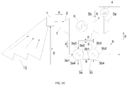
- FIG. 10 The following reference numerals are used in FIG. 10 : a heat source 1, a turbine 2, a high-temperature regenerator 3a, a low-temperature regenerator 3b, a hot side inlet 3as1, 3b1, a hot side outlet 3a2, 3b2, a cold side inlet 3a3, 3b3, a cold side outlet 3a4, 3b4, a pre-cooler 4, a main compressor 5a, a re-compressor 5b, a generator 6, a shaft 7, a circulating working medium 8.
- the Brayton cycle is a refrigeration cycle with gas as working medium and can be divided into simple Brayton cycle, recompression Brayton cycle, recompressed partially cooling Brayton cycle, and recompression reheats Brayton cycle or recompression intermediate cooling Brayton cycle.
- the heat source of the working medium can be provided by one or more of a tower solar concentrating system, a nuclear reactor, and a fossil fuel combustion system, and the heat absorption capacity of the working medium is flexible.
- the fossil fuel in the fossil fuel combustion system can be coal or natural gas.
- the first embodiment of the present invention provides a Brayton cycle which is a simple Brayton cycle.
- the heat source of the working medium is the tower solar concentrating system, and the heat source can provide a working medium at a temperature of more than 1,000°C, thus the entire Brayton cycle is at a high temperature.
- the Brayton cycle in the first embodiment includes the heat source 1, the turbine 2, the regenerator 3, the pre-cooler 4, the compressor 5, the generator 6, and the circulating working medium 8.
- the turbine 2, the generator 6 and the compressor 5 are connected by the same shaft 7; the heat source 1, the turbine 2, the regenerator 3, the pre-cooler 4, and the compressor 5 are sequentially connected by pipes; the circulating working medium 8 flows in the pipes.
- the outlet of the heat source 1 is connected to the inlet of the turbine 2; the outlet of the turbine 2 is connected to the hot side inlet 31 of the regenerator 3; the hot side outlet 32 of the regenerator 3 is connected to the inlet of the pre-cooler 4; the outlet of the pre-cooler 4 is connected to the inlet of the compressor 5; the outlet of the compressor 5 is connected to the cold side inlet 33 of the regenerator 3; the cold side outlet 34 of the regenerator 3 is connected to the inlet of the heat source 1, thus a circulating hot loop is formed.
- the circulating working medium 8 reaches a high temperature after heated by the heat source 1; the circulating working medium 8 enters the turbine 2 to expand and work; the circulating working medium 8 after the work sequentially passes through the regenerator 3 to recover heat, the pre-cooler 4 for cooling, the compressor 5 for compression, and enters the regenerator 3 again for heating, and finally enters the heat source 1 to be further heated to a high temperature. Therefore, the thermal cycle is completed.
- the circulating working medium 8 with high temperature after the expansion and working of the turbine 2 enters the regenerator 3 via the hot side inlet 31; the circulating working medium 8 with low temperature is compressed by the compressor 5 and enters the regenerator 2 via the cold side inlet 33.
- the circulating working medium 8 absorbs heat in the heat source 1; the circulating working medium 8 after the rise of temperature expands and works in the turbine 2; the turbine 2 drives the generator 6 to generate electricity through the shaft 7; the expanded circulating working medium 8 flows through the regenerator 3 to exchange heat; the circulating working medium 8 enters the pre-cooler 4, the compressor 5 and the regenerator 3 in turn after the fall of temperature; the circulating working medium 8 flows out of the cold side outlet 34 of the regenerator 3 and enters the heat source 1 again to absorb the radiation; the power required by the work of the compressor 5 is provided by the generator 6, thus a power generation cycle is completed.
- the circulating working medium 8 can be one of supercritical air, supercritical carbon dioxide, supercritical nitrogen, or supercritical Helium gas.
- the circulating working medium 8 is preferably supercritical carbon dioxide.
- the carbon dioxide is relatively low in critical pressure(7.38 MPa), and correspondingly low in the critical temperature (31°C), and has characteristics like relatively stable chemical properties, reliable safety performance, abundant reserves, low cost and availability. Therefore, carbon dioxide is considered to be one of the most promising energy transfer and conversion working media.
- the supercritical carbon dioxide has a high density and no phase change within a certain operating parameter range. Therefore, the power system equipment such as the compressor and the turbine with supercritical carbon dioxide as the circulating working medium has the advantages of small compressor power consumption, moderate working temperature for the turbine, compact structure, small volume, low manufacturing cost, and modular design.
- the turbine 2 is an important component of the Brayton cycle.
- the blades 12 of the turbine 2 are evenly arranged on the rotating element 16 which is mounted on the shaft 7 of the turbine 2.
- the energy possessed by the circulating working medium 8 is converted into kinetic energy as flowing through the nozzle.
- the circulating working medium 8 expands and impacts the blade 12, pushes the rotating element 16 to rotate, thereby driving the shaft 7 to rotate.
- the rotation of the shaft 7 directly drives the generator 6 to work and outputs mechanical work.
- the temperature of the circulating working medium 8 is also the inlet temperature of the turbine 2, and the rise of the temperature of the circulating working medium 8 can accelerate the rotation of the blade 12. With the increase of rotation speed of the shaft 7, the conversion efficiency of the generator 6 is improved, thus the system efficiency of the Brayton cycle is improved.
- the temperature of the circulating working medium 8 is higher than the temperature of the blade 12, and a heat transfer temperature difference exists therebetween.
- the high-temperature circulating working medium 8 transfers heat to the blade 12 mainly through heat conduction and heat radiation, so that the temperature of the blade 12 rises.
- the blade 12 needs to operate at high speed in the turbine 2, which leads to a possibility of fracture; the structural strength of the blade 12 at high-temperature state is weakened, and the fracture is more likely to occur.
- the blade 12 can be cooled by internal cooling, jet cooling, and thermal barrier coating cooling.
- the above cooling methods have limited cooling capacity for the turbine 2 which can be further cooled, so that the heat transfer temperature difference between the circulating working medium 8 and the blade 12 is limited, and the temperature of the circulating working medium 8 cannot be increased, that is, the hot end temperature of the Brayton cycle cannot be increased, and ultimately the system efficiency of the Brayton cycle cannot be further improved.
- the blade 12 of the turbine 2 in the present embodiment uses a characteristic spectral coating combined with a jet cooling technique in order to further cool the turbine 2 and increase the system efficiency of the Brayton cycle, so as to enhance the cooling effect for the blade 12.
- the blade 12 of the turbine 2 has a cooling working medium inlet 13 and a cooling working medium jet orifice 14.
- the blade 12 is provided as a cavity with hollow interior; the cooling working medium inlet 13 is preferably located in the blade 12; the cooling working medium jet orifice 14 is one or more and which are provided on the surface of the blade 12.
- the cooling working medium jet can enter the blade 12 for cooling through the cooling working medium inlet 13; the cooling working medium jet entering the blade 12 can also flow out through the cooling working medium jet orifice 14 and form a cooling working medium jet diaphragm layer 9 on the surface of the blade 12.
- the cooling working medium jet flows through the blade 12, performs a jet cooling, and then reaches the regenerator 3 together with the circulating working medium 8.
- the cooling working medium jet exchanges heat and is cooled in the regenerator 3; the condensed water in the liquefied form after cooling discharges from the liquid outlet of the regenerator 3, and is separated from the Brayton cycle.
- the cooling working medium jet enters the blade 12 from the cooling working medium inlet 13.
- One part of the cooling working medium jet is internally cooled, and the other part flows out through the cooling working medium jet orifice 14 and forms a cooling working medium jet diaphragm layer 9 on the surface of the blade 12.
- the convective heat transfer between the cooling working medium jet and the surface of the blade 12 achieves the cooling for the blade 12.
- a small jet channel (not shown) is also provided on the inner surface of the blade 12 in order to enhance the cooling effect for the blade 12.
- the cooling working medium jet flows from the jet channel into the interior of the blade 12, and is attached to the surface of the blade 12 to flow.
- the cooling working medium jet convectively exchanges heat with the surface of the blade 12, and carries away the heat of the blade 12.
- the surface of the blade 12 is provided with a spectral conversion coating 10 on the surface of which the above-described cooling working medium jet diaphragm layer 9 is formed by the cooling working medium.
- the spectral conversion coating 10 can convert the heat on the surface of the blade 12 into conversion characteristic band radiation A which is the radiation energy adjacent to the cooling working medium characteristic band radiation B of the cooling working medium.
- each substance has its characteristic absorption spectrum and several characteristic absorption peaks, each absorption peak has a certain spectral line width.
- the absorption efficiency is higher; when the characteristic absorption peaks of the substance partially overlap or do not overlap, the light wave absorption intensity and the absorption efficiency are lower.
- the central wavelength determines the center value of the wavelength distribution of the spectrum, and the spectral line width determines the concentration degree of the energy distribution of the spectrum.
- the spectral conversion coating 10 on the surface of the blade 12 converts the heat into conversion characteristic band radiation A which is adjacent to the cooling working medium characteristic band radiation B of the cooling working medium, thereby allowing the heat to be easily absorbed and carried away by the cooling working medium jet, reducing the heat radiation of the circulating working medium 8 to the surface of the blade 12, and enhancing the cooling for the blade 12.
- the invention can enhance the cooling for the blade 12 by using the characteristic spectral coating technology, ensure the safety of the blade 12, and increase the temperature of the circulating working medium 8 as much as possible within the range allowed by the material of the blade 12, thereby increasing the temperature of the circulating working medium 8 or the working temperature of the turbine 2, increasing the hot end temperature of the Brayton cycle, and improving the system efficiency of the Brayton cycle correspondingly.
- the use of the characteristic spectral coating cooling technology can effectively reduce the number of flow-paths of the cooling working medium jet on the surface of the blade 12, reduce the processing difficulty of the blade 12, and enhances the safety of the blade 12.
- the use of the characteristic spectral coating cooling technology can also reduce the consumption of the cooling working medium and save costs.
- the circulating working medium 8 is able to adopt a higher turbine inlet temperature due to the increase in the heat transfer temperature difference between the blades 12. The rise of the temperature of the circulating working medium 8 in the turbine 2 increases the working temperature of the circulating working medium 8 in the turbine 2, thereby improving the system efficiency of the Brayton cycle.
- the circulating working medium of the turbine in the mainstream Brayton cycle includes carbon dioxide and uses air as the cooling working medium.
- the component of the circulating working medium and the cooling working medium is similar and impure.
- the characteristic absorption peaks of the both have a certain range of overlap, which cannot effectively convert the heat of the blade transferred from the circulating working medium while shielding the heat transferred from the circulating working medium to the blade through radiation, that is, the characteristic spectral coating technology cannot be used to enhance cooling. Therefore, the Brayton cycle in the invention preferably uses water vapor as the cooling working medium, which is pure and the component is distinct from that of the circulating working medium.
- the characteristic absorption peaks of the circulating working medium and the cooling working medium do not overlap basically, which can shield the heat transferred to the blade by the circulating working medium through radiation while effectively converting the heat from the circulating working medium to the blade through heat conduction. That is, the characteristic spectral coating technology can be used to enhance the cooling.
- the main absorption peak of carbon dioxide is around 2.8 ⁇ m and 4.2 ⁇ m; the radiation absorption of the water vapor in the mid-far infrared (greater than 25 ⁇ m) band, 5 to 10 ⁇ m band, 2.5 to 2.8 ⁇ m band is relatively strong.
- the circulating working medium characteristic band radiation C of carbon dioxide is narrow and sharp, and the cooling working medium characteristic band radiation B of the water vapor is wider.
- the characteristic absorption peaks of the circulating working medium characteristic band radiation C and the cooling working medium characteristic band radiation B do not overlap basically.
- the cooling working medium characteristic band radiation B of the water vapor is wider; then the conversion characteristic band radiation A converted by the spectral conversion coating 10 has a wider range, which will help to reduce the design difficulty of the spectral conversion coating 10, and improve the applicability of the spectral conversion coating 10.
- the conversion characteristic band radiation A refers to the radiation energy near the central wavelength of the characteristic absorption peak of the cooling working medium characteristic band radiation B which is concentrated by the spectral line width of the characteristic absorption peak. As described above, the closer the central wavelength of the characteristic absorption peak of the conversion characteristic band radiation A is to the central wavelength of the characteristic absorption peak of the cooling working medium characteristic band radiation B, the easier the conversion characteristic band radiation A is absorbed by the cooling working medium jet diaphragm layer 9, and the better the cooling effect for the blade 12.
- the central wavelength of the characteristic absorption peak of the conversion characteristic band radiation A is the same as the central wavelength of the characteristic absorption peak of the cooling working medium characteristic band radiation B, and the spectral line width of the conversion characteristic band radiation A is much smaller than the spectral line width of the cooling working medium characteristic band radiation B.
- the conversion characteristic band radiation A which is converted by the spectral conversion coating 10, is more concentrated on a narrower wavelength range near the characteristic absorption peak of the cooling working medium characteristic band radiation B.
- the cooling working medium jet diaphragm layer 9 has the highest absorption efficiency for the conversion characteristic band radiation A, which results in a better cooling effect of the spectral conversion coating 10 for the blade 12.
- the temperature of the circulating working medium 8 can be greatly improved, which further improves the system efficiency of the Brayton cycle.
- the conversion characteristic band radiation A does not overlap the working medium characteristic band radiation C of the circulating working medium 8 which flows in the turbine 2.
- the conversion characteristic band radiation A does not overlap with the circulating working medium characteristic band radiation C and the cooling working medium characteristic band radiation B does not overlap with the working medium characteristic band radiation C.
- the blade 12 can utilize the spectral conversion coating 10 and the cooling working medium jet diaphragm layer 9 to shield part of the heat released by the circulating working medium 8.
- the heat transferred from the circulating working medium 8 to the blade 12 by heat conduction and heat radiation can be converted as much as possible into the conversion characteristic band radiation A, and then can be absorbed and carried away by the cooling working medium jet diaphragm layer 9, so as to prevent the circulating working medium 8 from transferring the heat to the blade 12 by radiation, reduce the temperature rise caused by the high-temperature circulating working medium 8 of the blade 12 and enhance the cooling effect for the blade 12.
- the cooling effect of the blade 12 after using the characteristic spectral coating and the jet cooling technology is now analyzed.
- the temperature of the blade 12 of the turbine 2 can reach about 1,100°C by utilizing the jet cooling technology, while the temperature of the cooling working medium jet is much lower than this temperature.
- the cooling working medium jet can be formed as an insulating layer between the high-temperature circulating working medium 8 and the blade 12; that is, a cooling working medium jet diaphragm layer 9 is formed. As shown in FIG.
- the radiation of the high-temperature circulating working medium 8 is reflected back to the circulating working medium 8, the heat conduction and heat radiation of the high-temperature circulating working medium 8 transfer part of the heat to the blade 12, the spectral conversion coating 10 will convert the above heat into the conversion characteristic band radiation A which is strongly absorbed by the cooling working medium, and the absorption efficiency is nearly 100%.
- the radiation intensity outwardly provided by the black body at 1,100°C is 20,149 W/m 2
- the band above 20 ⁇ m accounts for 1,168 W/m 2
- the ratio of radiation energy in the band 5 to 10 ⁇ m accounts for 32,417 W/m 2 .
- the black body radiation intensity is the energy conversion limitation of the spectral conversion coating 10; that is, the maximum value of the conversion characteristic band radiation A of the spectral conversion coating 10 at this temperature is the radiation energy value of the black body in this band. 5 to 10 ⁇ m is selected as the characteristic wavelength interval of the spectral conversion coating 10.
- the radiation amount of the external radiation between 5 to 10 ⁇ m is 5,089 W/m 2
- the radiation amount that can be transferred to the cooling working medium from the blade 12 at 1,100°C is 27,328 W/m 2
- the heat transfer coefficient between the cooling working medium jet diaphragm layer 9 and the spectral conversion coating 10 is about 500 W/m 2 , which means that it is also possible to increase the heat transfer temperature difference by about 50°C in the case of the blade 12 being isolated from radiation heat transfer.
- the heat transfer temperature difference of 50°C will bring about an improvement in the system efficiency of the Brayton cycle, and brings considerable benefits under the huge base number of power generation amount.
- an intermediate base layer 11 is provided between the spectral conversion coating 10 and the blade 12, and is made of a material with good thermal conductivity, generally a metal such as gold, silver, copper, aluminum or aluminum alloy and so on.
- the intermediate base layer 11 can transfer the heat on the blade 12 to the spectral conversion coating 10 which converts the above heat into the conversion characteristic band radiation A that can be easily absorbed by the cooling working medium and can be absorbed and carried away by the cooling working medium jet with lower temperature.
- the setting of the intermediate base layer 11 can not only transfer the heat on the surface of the blade 12 to the spectral conversion coating 10 better, but also improve the flatness of the surface of the blade 12.
- the spectral conversion coating 10 can be better attached to the surface of the blade 12 to ensure the adaptability of the spectral conversion coating 10.
- both the spectral conversion coating 10 and the intermediate base layer 11 are coated on the surface of the blade 12.
- the adaptability of the spectral conversion coating 10 and the surface strength of the blade 12 can be ensured by means of coating.
- the spectral conversion coating 10 is composed of nanoscale metal or semiconductor material with a certain structure.
- silver nano-rods of silver material can be adopted and arranged at certain spacing and angle, and stacked in multiple layers to form a spectral conversion coating 10 (that is, the light radiator).
- the black body radiation intensity is the energy conversion limitation of the spectral conversion coating 10, that is, the maximum value of the conversion characteristic band radiation A of the spectral conversion coating 10 at this temperature is the radiation energy value of the black body in this band.
- the spectral line width of the conversion characteristic band radiation A needs to be as small as possible and much smaller than the spectral line width of the cooling working medium characteristic band radiation B.
- the design of the spectral conversion coating 10 is based on a characteristic absorption peak of the cooling working medium, and the spectral line width of the conversion characteristic band radiation A mainly depends on the characteristic absorption spectrum of the cooling working medium as well as the material and the internal structure of the spectral conversion coating 10.
- the spectral conversion coating 10 sequentially includes a gold base layer 10a, an absorption cavity 10b, and a distributed reflection layer 10c, in which the gold base layer 10a is coated on the surface of the blade 12.
- the gold base layer 10a is provided on the surface of the intermediate base layer 11 due to the presence of the intermediate base layer 11.
- the gold base layer 10a can generate a harmonic resonance cavity with the distributed reflection layer 10c, and the absorption cavity 10b can absorb the above harmonic resonance and convert the absorbed heat into the radiation energy which is adjacent to the characteristic absorption peak of the cooling working medium.
- the gold base layer 10a when the spectral conversion coating 10 is working, the gold base layer 10a generate the harmonic resonance cavity with the distributed reflection layer 10c and effectively capture light in the absorption cavity 10b which absorbs the harmonic resonance and converts the absorbed heat.
- the gold base layer 10a and the distributed reflection layer 10c are utilized in combination with the absorption cavity 10b to obtain sharp, intense peak value of the absorption rate with small bandwidth, so as to improve the light absorptivity of the spectral conversion coating 10.
- the spectral conversion coating 10 can convert more heat on the blade 12 into the conversion characteristic band radiation A which is adjacent to the cooling working medium characteristic band radiation B, and the conversion characteristic band radiation A is absorbed and carried away by the cooling working medium jet, which increases the heat transfer temperature difference of the blade 12, improves the operating temperature of the turbine 2 in the Brayton cycle, thereby improving the system efficiency of the Brayton cycle.
- the distributed reflection layer 10c is a distributed Bragg reflector (DBR), and is composed of Ge and SiO 2 or Ge and ZnS; the absorption cavity 10b is composed of SiO 2 , and the gold base layer 10a is composed of gold.
- the absorption cavity 10b can be composed of a single layer or a multilayer structure, the length of which can affect the absorption peak value of the absorption spectrum and the absorption peak width of the spectral conversion coating 10.
- the number of layers n of the distributed reflection layer 10c also affects the absorption peak value and the corresponding absorption peak width.
- the length of the intermediate absorption cavity 10b is generally an integral multiple of the characteristic wavelength; the harmonic resonant of the distributed reflection layer 10c and the gold base layer 10a has the effect of selecting a wavelength.
- the waveband of the conversion characteristic band radiation A which is converted by the spectral conversion coating 10 can be changed by changing the number of layers n of the distributed reflection layer 10c and/or the length of the absorption cavity 10b.
- the spectral conversion coating 10 can be used in any component which requires enhanced cooling in the Brayton cycle, and is not limited to the turbine 2.
- the spectral conversion coating 10 is used in the heat-collecting cavity 1a of the heat source 1.
- the heat source 1 includes the heat-collecting cavity 1a.
- the inner surface of the heat-collecting cavity 1a is provided with a spectral conversion coating 10 which converts the radiation energy absorbed by the cavity of the heat-collecting cavity 1a into the conversion characteristic band radiation A which is strongly absorbed by the circulating working medium 8.
- the use of the characteristic spectral coating technology on the inner surface of the heat-collecting cavity 1a enhances the radiation heat exchange effect of the heat-collecting cavity 1a, prevents the temperature in the heat-collecting cavity 1a from being excessively high to burn out the heat-collecting cavity 1a, thereby ensuring the safe and efficient operation of the heat-collecting cavity 1, and improving the system efficiency of the Brayton cycle.
- the working temperature can be increased by about 50 °C using the spectral conversion coating 10 for the turbine 2 with an inlet temperature of about 1,400°C and the blade 12 temperature of about 1,100°C, and the system efficiency of the Brayton cycle can be improved by 1% to 2%.
- a second embodiment of the present invention further provides a Brayton cycle, and is a further improvement of the first embodiment.
- Those not specifically described include reference numerals and text descriptions, all of which are the same as in the first embodiment. Thus, detailed description thereof will be omitted.
- the main improvement of the second embodiment relative to the first embodiment is that the Brayton cycle is a recompression Brayton cycle which can consume a part of the compression work to greatly reduce the irreversible loss of the heat regenerative process, so that the cycle efficiency of the Brayton cycle is significantly improved.
- the heat source 1 is concentrated and heated by the solar energy condenser 15;
- the regenerator 3 is provided with two apparatuses which are a high-temperature regenerator 3a and a low-temperature regenerator 3brespectively;
- the compressor 5 is also provided with two apparatuses which are the main compressor 5a and re-compressor 5b respectively.
- the hot side inlet 3a1 and the hot side outlet 3a2 of the high-temperature regenerator 3a are connected to the outlet of the turbine 2 and the hot side inlet 3b1 of the low-temperature regenerator 3b respectively.
- the hot side outlet 3b2 of the low-temperature regenerator 3b is connected with the inlet of the pre-cooler 4 and the inlet of the re-compressor 5b respectively.
- the inlet and outlet of the main compressor 5a are connected to the outlet of the pre-cooler 4 and the cold side inlet 3a3 of the low-temperature regenerator 3b respectively.
- the cold side inlet 3a1 of the high-temperature regenerator 3a is connected to the outlet of the re-compressor 5b and the cold side outlet 3b4 of the low-temperature regenerator 3b respectively.
- the inlet and outlet of the heat source 1 are respectively connected to the cold side outlet 3a4 of the high-temperature regenerator 3a and the inlet of the turbine 2.
- the circulating working medium 8 reaches a high temperature after heated by the heat source 1 which is concentrated by the solar energy condenser 15, and enters the turbine 2 to expand and work.
- the blade 12 of the turbine 2 adopts the jet cooling and characteristic spectral coating technology to ensure the safe work of the blade 12, and the turbine 2 drives the generator 6 to generate electricity through the shaft 7.
- the circulating working medium 8 after the work recover heat by the high-temperature regenerator 3a and the low-temperature regenerator 3b.
- the high-temperature cooling working medium reaches the low-temperature regenerator 3b to be condensed and discharged out of the Brayton cycle from the low-temperature regenerator 3b liquid outlet.
- the circulating working medium 8 after the work sequentially flows through the high-temperature regenerator 3a and the low-temperature regenerator 3b to recover and shunt the heat.
- a stream of circulating working medium 8 is directly compressed into the high-temperature regenerator 3a by the re-compressor 5b; the other stream of circulating working medium 8 is cooled by the pre-cooler 4, and then compressed by the main compressor 5a and heated by the low-temperature regenerator 3b.
- the two streams of circulating working mediums 8 flowing out from the re-compressor 5b and the low-temperature regenerator 3b converge with each other; the circulating working medium 8 after the convergence sequentially enters the high-temperature regenerator 3a and the heat source 1 to be further heated to a high temperature, thus the thermal cycle is completed.
- Brayton cycle structure is relatively complicated and may include processes like reheating, heat regeneration, recompression, partial cooling, intermediate cooling, and so on, and the embodiments of the present invention only describe the basic structure.
Landscapes
- Engineering & Computer Science (AREA)
- Mechanical Engineering (AREA)
- General Engineering & Computer Science (AREA)
- Chemical & Material Sciences (AREA)
- Combustion & Propulsion (AREA)
- Sustainable Development (AREA)
- Sustainable Energy (AREA)
- Life Sciences & Earth Sciences (AREA)
- Materials Engineering (AREA)
- Physics & Mathematics (AREA)
- High Energy & Nuclear Physics (AREA)
- Chemical Kinetics & Catalysis (AREA)
- Turbine Rotor Nozzle Sealing (AREA)
Abstract
Description
- The present invention relates to the technical field of solar thermal power generation, especially a turbine and a Brayton cycle including the same.
- The Brayton cycle, also known as the Joule cycle, is a thermodynamic cycle with gas as working medium consisting of four processes: isentropic compression, isobaric heat absorption, isentropic expansion, and isobaric cooling. The Brayton cycle, with gas at supercritical state as the working medium, has significant advantages of efficiency. The compressor operating point is provided at a high-density area near a pseudo-critical temperature, and the heat exchanger operating point is provided at a low-density area after the pseudo-critical temperature by using abruptly changing phenomenon of supercritical working medium at the pseudo-critical region, in order to reduce the compression power consumption and reach higher efficiency when the cooling of the working medium is ensured.
- A turbine is a machine that converts the energy contained in a fluid medium into mechanical work and is an important component in the Brayton cycle. The most important component of the turbine is a rotating element (rotor or impeller) mounted on a shaft of the turbine, and the rotating element has blades evenly arranged along the circumference. In the Brayton cycle, the energy of the high-temperature working medium is converted into kinetic energy when flowing through the nozzle in the flow; the working medium impacts the blades when flowing through the rotating element, and drives the rotating element to rotate, thereby driving the rotation of the shaft, and converting the thermal energy of the working medium into mechanical energy. The shaft drives other machines directly or via a transmission mechanism to output mechanical work.
- Currently, the operating temperature of the Brayton cycle can reach above 1,350°C, and the temperature of the blade in the turbine can be cooled to below 950°C by the prior art. The system efficiency of the Brayton cycle is positively correlated with the hot end temperature of the cycle (that is, the inlet temperature of the working medium entering the turbine, and the working temperature of the turbine). Therefore, increasing the hot end temperature of the Brayton cycle is one of the main ways to improve system efficiency. The cycle parameters of supercritical carbon dioxide Brayton cycle at high temperatures are limited due to the extreme conditions such as structural strength and manufacturing of the system unit material. Therefore, the temperature of the existing designed supercritical carbon dioxide Brayton cycle is generally below 700°C. However, it can be found from the existing air Brayton cycle that the Brayton cycle with the supercritical working medium as the circulating working medium has the potential to operate at temperatures above 1,000°C. Under this temperature condition, the thermal cycle efficiency of supercritical carbon dioxide Brayton cycle will be greatly improved, and even may exceed 55%, which will be nearly 37.5% higher than the thermal efficiency (slightly more than 40%) of the most advanced large-sized steam power apparatus, and will be much higher than the most widely used steam Rankine cycle (the average thermal efficiency of the steam Rankine cycle is only 34%) at present.
- Turbine blade cooling is also one of the main challenges for the supercritical carbon dioxide Brayton cycle at high temperatures. The current cooling method has limited cooling capacity for turbine blades, and cannot further cool the turbine blades, which limits the heat transfer temperature difference between the working medium and the blades, so that the temperature of the working medium cannot be increased, that is, the hot end temperature of the Brayton cycle cannot be improved, thus the system efficiency of the Brayton cycle cannot be improved.
- The present invention provides a turbine based on the above technical problems. The turbine of the invention can enhance the cooling effect of the turbine blades, and can also increase the temperature of the circulating working medium and the hot end temperature of the Brayton cycle while ensuring the safe and efficient operation of the turbine, thereby improving the system efficiency of the Brayton cycle.
- Specifically, the present invention is described as follows:
A turbine, including blades with a cooling working medium inlet and a cooling working medium jet orifice; the blade is provided as a cavity with hollow interior; the cooling working medium jet orifice is one or more which are provided on the blade surface; the cooling working medium jet can enter the blade for cooling through the cooling working medium inlet; the blade surface is provided with a spectral conversion coating; the cooling working medium jet entering the blade can also flow out through the cooling working medium jet orifice, and can form a cooling working medium jet diaphragm layer on the surface of the spectral conversion coating. The spectral conversion coating can convert the heat of the blade surface into the conversion characteristic band radiation which is the radiation energy adjacent to the cooling working medium characteristic band radiation of the cooling working medium. - Compared with the prior art, the temperature of the circulating working medium is higher than the temperature of the turbine blade; the circulating working medium transfers part of the heat to the blade through heat conduction and heat radiation. Meanwhile the heat transferred by the circulating working medium to the blade surface can be converted into conversion characteristic band radiation by the spectral conversion coating; the conversion characteristic band radiation is adjacent to the cooling working medium characteristic band radiation of the cooling working medium, and is strongly absorbed by the cooling working medium jet and carried away, thereby reducing the thermal radiation to the blade surface by the circulating working medium, and enhancing the cooling for the blade. The invention can enhance the cooling of the blade using characteristic spectral coating technology to ensure the safety of the blade, increase the temperature of the circulating working medium as much as possible within the range allowed by the blade material, increase the temperature of the circulating working medium, that is, the working temperature of the turbine, and increase the hot end temperature of the Brayton cycle, thereby correspondingly increasing the system efficiency of the Brayton cycle.
- In addition, preferably, the conversion characteristic band radiation refers to the radiation energy near the central wavelength of the characteristic absorption peak of the cooling working medium characteristic band radiation which is concentrated by the spectral line width of the characteristic absorption peak.
- According to the preferred embodiment, the closer the central wavelength of the characteristic absorption peak of the conversion characteristic band radiation is to the central wavelength of the characteristic absorption peak of the cooling working medium characteristic band radiation, the easier the conversion characteristic band radiation is absorbed by the cooling working medium jet diaphragm layer, and the better the cooling effect for the blade.
- In addition, preferably, the central wavelength of the characteristic absorption peak of the conversion characteristic band radiation is the same as the central wavelength of the characteristic absorption peak of the cooling working medium characteristic band radiation, and the spectral line width of the conversion characteristic band radiation is much smaller than that of the cooling working medium characteristic band radiation.
- According to the preferred embodiment, the conversion characteristic band radiation which is converted by the spectral conversion coating is more concentrated within a narrower wavelength range near the characteristic absorption peak of the cooling working medium characteristic band radiation, and the cooling working medium jet diaphragm layer has the highest absorption efficiency for the conversion characteristic band radiation, which results in a better cooling effect of the spectral conversion coating on the blade. Correspondingly, the temperature of the circulating working medium can be greatly improved, which further improves the system efficiency of the Brayton cycle.
- In addition, preferably, the conversion characteristic band radiation does not overlap with the circulating working medium characteristic band radiation of the circulating working medium flowing in the turbine.
- According to the preferred embodiment, the conversion characteristic band radiation does not overlap with the circulating working medium characteristic band radiation, namely the cooling working medium characteristic band radiation does not overlap with the circulating working medium characteristic band radiation. The blade can utilize the spectral conversion coating and the cooling working medium jet diaphragm layer to shielding part of the heat released by the circulating working medium, and can convert the remainder of the heat released by the circulating working medium into conversion characteristic band radiation as much as possible, and then the radiation is absorbed and carried away by the cooling working medium jet diaphragm layer, thereby enhancing the cooling effect for the blade.
- In addition, preferably, an intermediate base layer with good thermal conductivity is provided between the spectral conversion coating and the blade, and the intermediate base layer can transfer heat on the blade to the spectral conversion coating.
- According to the preferred embodiment, the intermediate base layer can better transfer the heat on the blade surface to the spectral conversion coating, as well as facilitate better attachment of the spectral conversion coating to the blade surface.
- Further, preferably, the material of the spectral conversion coating is metal or semiconductor, and the spectral conversion coating is coated on the blade surface.
- According to the preferred embodiment, the coating method can ensure the adaptability of the spectral conversion coating and the surface strength of the blade.
- In addition, preferably, the spectral conversion coating includes a gold base layer which is in contact with the blade surface, an absorption cavity and a distributed reflection layer sequentially distributed on the gold base layer, which can generate a harmonic resonance cavity with the distributed reflection layer, and the absorption cavity can absorb the above harmonic resonance and convert the absorbed heat into conversion characteristic band radiation.
- According to the preferred embodiment, the gold base layer, the distributed reflection layer, and the absorption cavity are used together to obtain a sharp, intense conversion characteristic band radiation with small bandwidth and to improve the light absorption rate of the spectral conversion coating. The spectral conversion coating can convert the heat on the blade into the conversion characteristic band radiation to allow the heat to be absorbed and carried away by the cooling working medium jet, so as to increase the heat transfer temperature difference between the circulating working medium and the blade and increase the temperature of the circulating working medium, thereby improving the system efficiency of the Brayton cycle.
- Further, preferably, the distributed reflection layer is composed of Ge and SiO2 or Ge and ZnS.
- According to another aspect, a Brayton cycle is provided, where the Brayton cycle includes a heat source, a regenerator, a pre-cooler, a compressor, a generator, a circulating working medium circulating in the Brayton cycle, and a turbine according to any of the foregoing technical solutions. The turbine, the generator, and the compressor are connected by the same shaft; the heat source, the turbine, the hot side inlets and the hot side outlets of the regenerator, the pre-cooler, the compressor, and the cold side inlets and the cold side outlets of the regenerator are sequentially connected by pipes to form a cycle.
- The outlet of the heat source is connected to the inlet of the turbine; the outlet of the turbine is connected to the hot side inlet of the regenerator; the hot side outlet of the regenerator is connected to the inlet of the pre-cooler; the outlet of the pre-cooler is connected to the inlet of the compressor; the outlet of the compressor is connected to the cold side inlet of the regenerator; and the cold side outlets of the regenerator are connected to the inlet of the heat source, thus a circulating hot loop is formed.
- The circulating working medium absorbs heat from the heat source; the circulating working medium after the rise of temperature expands and works in the turbine; the turbine drives the generator to generate electricity through the shaft; the expanded circulating working medium flows through the regenerator to exchange heat; the circulating working medium enters the pre-cooler, the compressor and the regenerator in turn after the fall of temperature; the circulating working medium flows out of the cold side outlets of the regenerator and enters the heat source again to absorb the radiation energy; the power required by the work of the compressor is provided by the generator, thus a power generation cycle is completed.
- Compared with the prior art, the turbine of the Brayton cycle provided by the invention uses a characteristic spectral coating and a jet cooling technology, so as to enhance the radiant cooling effect of the turbine, increase the heat transfer temperature difference between the blade and the circulating working medium, and increase the temperature of the circulating working medium and the hot end temperature of the Brayton cycle while ensuring the safe and efficient operation of the turbine, thereby improving the system efficiency of the Brayton cycle.
- In addition, preferably, the heat source includes a heat-collecting cavity; the inner surface of the heat-collecting cavity is provided with a spectral conversion coating which converts the radiation absorbed by the cavity of the heat-collecting cavity into the conversion characteristic band radiation which is strongly absorbed by the circulating working medium.
- According to the preferred embodiment, the radiant heat exchange is enhanced by using the characteristic spectral coating on the surface of the heat-collecting cavity to prevent the excessively high temperature in the heat-collecting cavity from burning out the heat-collecting cavity, thereby ensuring the safe and efficient operation of the heat-collecting cavity.
-
-
FIG. 1 is a schematic view of a Brayton cycle according to a first embodiment of the present invention. -
FIG. 2 is a schematic view showing the simple structure inside the turbine of the present invention. -
FIG. 3 is a structural schematic view of the reinforced cooling of a blade in the first embodiment of the present invention. -
FIG. 4 is a schematic diagram showing the relationship between the conversion characteristic band radiation and the characteristic band radiation of water vapor and carbon dioxide in the present invention. -
FIG. 5 is a schematic diagram showing heat transfer between a circulating working medium and the blade in the first embodiment of the present invention. -
FIG. 6 is a structural schematic diagram of a spectral conversion coating in the first embodiment of the present invention. -
FIG. 7 is a schematic diagram showing the relationship between the number of layers of the distributed reflection layer and the radiation absorption rate of the circulating working medium. -
FIG. 8 is a schematic diagram showing the relationship between the number of layers of the distributed reflection layer and the characteristic absorption peak of the radiation. -
FIG. 9 is a structural schematic view of enhanced radiation heat exchange of a heat-collecting cavity in the first embodiment of the present invention. -
FIG. 10 is a schematic view of the Brayton cycle according to the second embodiment of the present invention. - The following reference numerals are used in
FIG. 1 :
aheat source 1, aturbine 2, aregenerator 3, ahot side inlet 31, ahot side outlet 32, acold side inlet 33, acold side outlet 34, a pre-cooler 4, acompressor 5, agenerator 6, ashaft 7, a circulating workingmedium 8. - The following reference numerals are used in
FIG. 2 :
aturbine 2, ashaft 7, a circulating workingmedium 8, ablade 12, a rotatingelement 16. - The following reference numerals are used in
FIG. 3 :
a circulating workingmedium 8, a cooling working mediumjet diaphragm layer 9, aspectral conversion coating 10, a gold base layer 10a, anabsorption cavity 10b, a distributedreflection layer 10c, aintermediate base 11, ablade 12, a cooling workingmedium inlet 13, a cooling workingmedium jet orifice 14. - The following reference numerals are used in
FIG. 4 :
the conversion characteristic band radiation A, the cooling working medium characteristic band radiation B, the circulating working medium characteristic band radiation C. - The following reference numerals are used in
FIG. 5 :
a circulating workingmedium 8, ablade 12, a cooling workingmedium inlet 13, a cooling workingmedium jet orifice 14, the conversion characteristic band radiation A, the cooling working medium characteristic band radiation B, the circulating working medium characteristic band radiation C. - The following reference numerals are used in
FIG. 6 :
a cold sid a gold base layer 10a, anabsorption cavity 10b, a distributedreflection layer 10c. - The following reference numerals are used in
FIG. 8 :
a distributedreflection layer 10c. - The following reference numerals are used in
FIG. 9 :
a heat-collectingcavity 1a, a circulating workingmedium 8, aspectral conversion coating 10, aintermediate base 11. - The following reference numerals are used in
FIG. 10 :
aheat source 1, aturbine 2, a high-temperature regenerator 3a, a low-temperature regenerator 3b, a hot side inlet 3as1, 3b1, a hot side outlet 3a2, 3b2, a cold side inlet 3a3, 3b3, a cold side outlet 3a4, 3b4, apre-cooler 4, amain compressor 5a, a re-compressor 5b, agenerator 6, ashaft 7, a circulating workingmedium 8. - The present invention will be further described in detail below in conjunction with the accompanying drawings. The structure of the turbine and the Brayton cycle including the same are schematically simplified in the drawings.
- In the description of the present invention, it will be understood that the orientation or positional relationship indicated by terms like "upper", "lower", "front", "back", "left", "right", "top", "bottom", "inside", "outside" are based on that shown in the drawings. The terms are merely for the convenience and simplicity of description rather than an indication or an implication that the apparatus or element must have a specific orientation and must be configured and operated in the specific orientation. Thus the terms should not be construed as a limit to the invention.
- The Brayton cycle is a refrigeration cycle with gas as working medium and can be divided into simple Brayton cycle, recompression Brayton cycle, recompressed partially cooling Brayton cycle, and recompression reheats Brayton cycle or recompression intermediate cooling Brayton cycle. In the Brayton cycle, the heat source of the working medium can be provided by one or more of a tower solar concentrating system, a nuclear reactor, and a fossil fuel combustion system, and the heat absorption capacity of the working medium is flexible. The fossil fuel in the fossil fuel combustion system can be coal or natural gas.
- The first embodiment of the present invention provides a Brayton cycle which is a simple Brayton cycle. The heat source of the working medium is the tower solar concentrating system, and the heat source can provide a working medium at a temperature of more than 1,000°C, thus the entire Brayton cycle is at a high temperature.
- Referring to
FIG. 1 , the Brayton cycle in the first embodiment includes theheat source 1, theturbine 2, theregenerator 3, thepre-cooler 4, thecompressor 5, thegenerator 6, and the circulating workingmedium 8. Theturbine 2, thegenerator 6 and thecompressor 5 are connected by thesame shaft 7; theheat source 1, theturbine 2, theregenerator 3, thepre-cooler 4, and thecompressor 5 are sequentially connected by pipes; the circulating workingmedium 8 flows in the pipes. - Specifically, the outlet of the
heat source 1 is connected to the inlet of theturbine 2; the outlet of theturbine 2 is connected to thehot side inlet 31 of theregenerator 3; thehot side outlet 32 of theregenerator 3 is connected to the inlet of thepre-cooler 4; the outlet of thepre-cooler 4 is connected to the inlet of thecompressor 5; the outlet of thecompressor 5 is connected to thecold side inlet 33 of theregenerator 3; thecold side outlet 34 of theregenerator 3 is connected to the inlet of theheat source 1, thus a circulating hot loop is formed. - During work, the circulating working
medium 8 reaches a high temperature after heated by theheat source 1; the circulating workingmedium 8 enters theturbine 2 to expand and work; the circulating workingmedium 8 after the work sequentially passes through theregenerator 3 to recover heat, the pre-cooler 4 for cooling, thecompressor 5 for compression, and enters theregenerator 3 again for heating, and finally enters theheat source 1 to be further heated to a high temperature. Therefore, the thermal cycle is completed. The circulating workingmedium 8 with high temperature after the expansion and working of theturbine 2 enters theregenerator 3 via thehot side inlet 31; the circulating workingmedium 8 with low temperature is compressed by thecompressor 5 and enters theregenerator 2 via thecold side inlet 33. The circulating workingmedium 8 with high-temperature and low-temperature exchanges heat in theregenerator 3. After heat exchange, the circulating workingmedium 8 flows out from thehot side outlet 32 and thecold side outlet 34 respectively. - For the power generation cycle, the circulating working
medium 8 absorbs heat in theheat source 1; the circulating workingmedium 8 after the rise of temperature expands and works in theturbine 2; theturbine 2 drives thegenerator 6 to generate electricity through theshaft 7; the expanded circulating workingmedium 8 flows through theregenerator 3 to exchange heat; the circulating workingmedium 8 enters thepre-cooler 4, thecompressor 5 and theregenerator 3 in turn after the fall of temperature; the circulating workingmedium 8 flows out of thecold side outlet 34 of theregenerator 3 and enters theheat source 1 again to absorb the radiation; the power required by the work of thecompressor 5 is provided by thegenerator 6, thus a power generation cycle is completed. - In the Brayton cycle, the circulating working
medium 8 can be one of supercritical air, supercritical carbon dioxide, supercritical nitrogen, or supercritical Helium gas. In the present embodiment, the circulating workingmedium 8 is preferably supercritical carbon dioxide. The carbon dioxide is relatively low in critical pressure(7.38 MPa), and correspondingly low in the critical temperature (31°C), and has characteristics like relatively stable chemical properties, reliable safety performance, abundant reserves, low cost and availability. Therefore, carbon dioxide is considered to be one of the most promising energy transfer and conversion working media. The supercritical carbon dioxide has a high density and no phase change within a certain operating parameter range. Therefore, the power system equipment such as the compressor and the turbine with supercritical carbon dioxide as the circulating working medium has the advantages of small compressor power consumption, moderate working temperature for the turbine, compact structure, small volume, low manufacturing cost, and modular design. - As mentioned, referring to
FIG. 2 , theturbine 2 is an important component of the Brayton cycle. Theblades 12 of theturbine 2 are evenly arranged on therotating element 16 which is mounted on theshaft 7 of theturbine 2. The energy possessed by the circulating workingmedium 8 is converted into kinetic energy as flowing through the nozzle. When flowing through therotating element 16, the circulating workingmedium 8 expands and impacts theblade 12, pushes therotating element 16 to rotate, thereby driving theshaft 7 to rotate. The rotation of theshaft 7 directly drives thegenerator 6 to work and outputs mechanical work. The temperature of the circulating workingmedium 8 is also the inlet temperature of theturbine 2, and the rise of the temperature of the circulating workingmedium 8 can accelerate the rotation of theblade 12. With the increase of rotation speed of theshaft 7, the conversion efficiency of thegenerator 6 is improved, thus the system efficiency of the Brayton cycle is improved. - In the Brayton cycle, the temperature of the circulating working
medium 8 is higher than the temperature of theblade 12, and a heat transfer temperature difference exists therebetween. The high-temperature circulating workingmedium 8 transfers heat to theblade 12 mainly through heat conduction and heat radiation, so that the temperature of theblade 12 rises. Theblade 12 needs to operate at high speed in theturbine 2, which leads to a possibility of fracture; the structural strength of theblade 12 at high-temperature state is weakened, and the fracture is more likely to occur. Considering the material characteristics of theblade 12, it is only possible to reduce the temperature of the circulating workingmedium 8 or to cool theturbine 2 so as to prevent the excessively high temperature from burning out theturbine 2. If the temperature of the circulating workingmedium 8 is lowered, the system efficiency of the Brayton cycle will be reduced. Therefore, by adopting the cooling method of cooling theturbine 2, both theturbine 2 and the temperature of the circulatingmedium 8 is ensured, thereby ensuring the system efficiency of the Brayton cycle. - For the Brayton cycle, the
blade 12 can be cooled by internal cooling, jet cooling, and thermal barrier coating cooling. However, the above cooling methods have limited cooling capacity for theturbine 2 which can be further cooled, so that the heat transfer temperature difference between the circulating workingmedium 8 and theblade 12 is limited, and the temperature of the circulating workingmedium 8 cannot be increased, that is, the hot end temperature of the Brayton cycle cannot be increased, and ultimately the system efficiency of the Brayton cycle cannot be further improved. Theblade 12 of theturbine 2 in the present embodiment uses a characteristic spectral coating combined with a jet cooling technique in order to further cool theturbine 2 and increase the system efficiency of the Brayton cycle, so as to enhance the cooling effect for theblade 12. - Specifically, referring to
FIG. 3 , theblade 12 of theturbine 2 has a cooling workingmedium inlet 13 and a cooling workingmedium jet orifice 14. Theblade 12 is provided as a cavity with hollow interior; the cooling workingmedium inlet 13 is preferably located in theblade 12; the cooling workingmedium jet orifice 14 is one or more and which are provided on the surface of theblade 12. The cooling working medium jet can enter theblade 12 for cooling through the cooling workingmedium inlet 13; the cooling working medium jet entering theblade 12 can also flow out through the cooling workingmedium jet orifice 14 and form a cooling working mediumjet diaphragm layer 9 on the surface of theblade 12. - The cooling working medium jet flows through the
blade 12, performs a jet cooling, and then reaches theregenerator 3 together with the circulating workingmedium 8. The cooling working medium jet exchanges heat and is cooled in theregenerator 3; the condensed water in the liquefied form after cooling discharges from the liquid outlet of theregenerator 3, and is separated from the Brayton cycle. - With jet cooling technology, the cooling working medium jet enters the
blade 12 from the cooling workingmedium inlet 13. One part of the cooling working medium jet is internally cooled, and the other part flows out through the cooling workingmedium jet orifice 14 and forms a cooling working mediumjet diaphragm layer 9 on the surface of theblade 12. The convective heat transfer between the cooling working medium jet and the surface of theblade 12 achieves the cooling for theblade 12. - In addition, a small jet channel (not shown) is also provided on the inner surface of the
blade 12 in order to enhance the cooling effect for theblade 12. The cooling working medium jet flows from the jet channel into the interior of theblade 12, and is attached to the surface of theblade 12 to flow. The cooling working medium jet convectively exchanges heat with the surface of theblade 12, and carries away the heat of theblade 12. - In particular, the surface of the
blade 12 is provided with aspectral conversion coating 10 on the surface of which the above-described cooling working mediumjet diaphragm layer 9 is formed by the cooling working medium. Thespectral conversion coating 10 can convert the heat on the surface of theblade 12 into conversion characteristic band radiation A which is the radiation energy adjacent to the cooling working medium characteristic band radiation B of the cooling working medium. - Each substance has its characteristic absorption spectrum and several characteristic absorption peaks, each absorption peak has a certain spectral line width. When the light wave absorption intensity in the vicinity of the characteristic absorption peak of the substance is greater, the absorption efficiency is higher; when the characteristic absorption peaks of the substance partially overlap or do not overlap, the light wave absorption intensity and the absorption efficiency are lower. The central wavelength determines the center value of the wavelength distribution of the spectrum, and the spectral line width determines the concentration degree of the energy distribution of the spectrum.
- When the high-temperature circulating working
medium 8 transfers heat to theblade 12 through heat conduction and heat radiation, thespectral conversion coating 10 on the surface of theblade 12 converts the heat into conversion characteristic band radiation A which is adjacent to the cooling working medium characteristic band radiation B of the cooling working medium, thereby allowing the heat to be easily absorbed and carried away by the cooling working medium jet, reducing the heat radiation of the circulating workingmedium 8 to the surface of theblade 12, and enhancing the cooling for theblade 12. The invention can enhance the cooling for theblade 12 by using the characteristic spectral coating technology, ensure the safety of theblade 12, and increase the temperature of the circulating workingmedium 8 as much as possible within the range allowed by the material of theblade 12, thereby increasing the temperature of the circulating workingmedium 8 or the working temperature of theturbine 2, increasing the hot end temperature of the Brayton cycle, and improving the system efficiency of the Brayton cycle correspondingly. - In addition, the use of the characteristic spectral coating cooling technology can effectively reduce the number of flow-paths of the cooling working medium jet on the surface of the
blade 12, reduce the processing difficulty of theblade 12, and enhances the safety of theblade 12. The use of the characteristic spectral coating cooling technology can also reduce the consumption of the cooling working medium and save costs. In particular, the circulating workingmedium 8 is able to adopt a higher turbine inlet temperature due to the increase in the heat transfer temperature difference between theblades 12. The rise of the temperature of the circulating workingmedium 8 in theturbine 2 increases the working temperature of the circulating workingmedium 8 in theturbine 2, thereby improving the system efficiency of the Brayton cycle. - Currently, the circulating working medium of the turbine in the mainstream Brayton cycle includes carbon dioxide and uses air as the cooling working medium. However, the component of the circulating working medium and the cooling working medium is similar and impure. The characteristic absorption peaks of the both have a certain range of overlap, which cannot effectively convert the heat of the blade transferred from the circulating working medium while shielding the heat transferred from the circulating working medium to the blade through radiation, that is, the characteristic spectral coating technology cannot be used to enhance cooling. Therefore, the Brayton cycle in the invention preferably uses water vapor as the cooling working medium, which is pure and the component is distinct from that of the circulating working medium. The characteristic absorption peaks of the circulating working medium and the cooling working medium do not overlap basically, which can shield the heat transferred to the blade by the circulating working medium through radiation while effectively converting the heat from the circulating working medium to the blade through heat conduction. That is, the characteristic spectral coating technology can be used to enhance the cooling.
- Differences exist in the bands of the characteristic absorption peaks of different substances. As shown in Table 1, the main absorption peak of carbon dioxide is around 2.8 µm and 4.2 µm; the radiation absorption of the water vapor in the mid-far infrared (greater than 25 µm) band, 5 to 10 µm band, 2.5 to 2.8 µm band is relatively strong.
Table 1 Difference of characteristic absorption peak between carbon dioxide and water vapor (greater than 2.5 µm) Band (cm-1) Absorption Intensity Level of Carbon Dioxide Absorption Intensity Level of Water Vapor 0-50 can be ignored 10-19 50-350 can be ignored 10-18 350-430 can be ignored 10-19 430-500 10-26 10-19 500-580 can be ignored 10-20 580-625 10-21 10-21 625-720 10-19 10-21 720-1000 10-23 10-23 1000-1100 10-23 10-21 1100-1800 can be ignored 10-19 1800-2000 10-23 10-19 2000-2120 can be ignored 10-24 2220-2300 10-21 10-24 2300-2380 10-18 10-24 2380-3000 10-25 10-23 3000-3500 10-25 10-21 3500-3800 10-20 10-19 3800-4000 can be ignored 10-19 - Referring to
FIG. 4 , the circulating working medium characteristic band radiation C of carbon dioxide is narrow and sharp, and the cooling working medium characteristic band radiation B of the water vapor is wider. The characteristic absorption peaks of the circulating working medium characteristic band radiation C and the cooling working medium characteristic band radiation B do not overlap basically. The cooling working medium characteristic band radiation B of the water vapor is wider; then the conversion characteristic band radiation A converted by thespectral conversion coating 10 has a wider range, which will help to reduce the design difficulty of thespectral conversion coating 10, and improve the applicability of thespectral conversion coating 10. - The conversion characteristic band radiation A refers to the radiation energy near the central wavelength of the characteristic absorption peak of the cooling working medium characteristic band radiation B which is concentrated by the spectral line width of the characteristic absorption peak. As described above, the closer the central wavelength of the characteristic absorption peak of the conversion characteristic band radiation A is to the central wavelength of the characteristic absorption peak of the cooling working medium characteristic band radiation B, the easier the conversion characteristic band radiation A is absorbed by the cooling working medium
jet diaphragm layer 9, and the better the cooling effect for theblade 12. - In particular, the central wavelength of the characteristic absorption peak of the conversion characteristic band radiation A is the same as the central wavelength of the characteristic absorption peak of the cooling working medium characteristic band radiation B, and the spectral line width of the conversion characteristic band radiation A is much smaller than the spectral line width of the cooling working medium characteristic band radiation B. The conversion characteristic band radiation A which is converted by the
spectral conversion coating 10, is more concentrated on a narrower wavelength range near the characteristic absorption peak of the cooling working medium characteristic band radiation B. The cooling working mediumjet diaphragm layer 9 has the highest absorption efficiency for the conversion characteristic band radiation A, which results in a better cooling effect of thespectral conversion coating 10 for theblade 12. Correspondingly, the temperature of the circulating workingmedium 8 can be greatly improved, which further improves the system efficiency of the Brayton cycle. - Further, referring to
FIG. 4 , the conversion characteristic band radiation A does not overlap the working medium characteristic band radiation C of the circulating workingmedium 8 which flows in theturbine 2. The conversion characteristic band radiation A does not overlap with the circulating working medium characteristic band radiation C and the cooling working medium characteristic band radiation B does not overlap with the working medium characteristic band radiation C. Referring toFIG. 5 , theblade 12 can utilize thespectral conversion coating 10 and the cooling working mediumjet diaphragm layer 9 to shield part of the heat released by the circulating workingmedium 8. The heat transferred from the circulating workingmedium 8 to theblade 12 by heat conduction and heat radiation can be converted as much as possible into the conversion characteristic band radiation A, and then can be absorbed and carried away by the cooling working mediumjet diaphragm layer 9, so as to prevent the circulating workingmedium 8 from transferring the heat to theblade 12 by radiation, reduce the temperature rise caused by the high-temperature circulating workingmedium 8 of theblade 12 and enhance the cooling effect for theblade 12. - The cooling effect of the
blade 12 after using the characteristic spectral coating and the jet cooling technology is now analyzed. For specific analysis, when the inlet temperature of the high-temperature turbine 2 is at 1,500°C, the temperature of theblade 12 of theturbine 2 can reach about 1,100°C by utilizing the jet cooling technology, while the temperature of the cooling working medium jet is much lower than this temperature. The cooling working medium jet can be formed as an insulating layer between the high-temperature circulating workingmedium 8 and theblade 12; that is, a cooling working mediumjet diaphragm layer 9 is formed. As shown inFIG. 5 , the radiation of the high-temperature circulating workingmedium 8 is reflected back to the circulating workingmedium 8, the heat conduction and heat radiation of the high-temperature circulating workingmedium 8 transfer part of the heat to theblade 12, thespectral conversion coating 10 will convert the above heat into the conversion characteristic band radiation A which is strongly absorbed by the cooling working medium, and the absorption efficiency is nearly 100%. It can be obtained that, according to the Planck law of radiation, the radiation intensity outwardly provided by the black body at 1,100°C is 20,149 W/m2, while the band above 20 µm accounts for 1,168 W/m2 and the ratio of radiation energy in theband 5 to 10 µm accounts for 32,417 W/m2. The black body radiation intensity is the energy conversion limitation of thespectral conversion coating 10; that is, the maximum value of the conversion characteristic band radiation A of thespectral conversion coating 10 at this temperature is the radiation energy value of the black body in this band. 5 to 10 µm is selected as the characteristic wavelength interval of thespectral conversion coating 10. When the temperature of the cooling working medium is 400°C, the radiation amount of the external radiation between 5 to 10 µm is 5,089 W/m2, then the radiation amount that can be transferred to the cooling working medium from theblade 12 at 1,100°C is 27,328 W/m2, and the heat transfer coefficient between the cooling working mediumjet diaphragm layer 9 and thespectral conversion coating 10 is about 500 W/m2, which means that it is also possible to increase the heat transfer temperature difference by about 50°C in the case of theblade 12 being isolated from radiation heat transfer. The heat transfer temperature difference of 50°C will bring about an improvement in the system efficiency of the Brayton cycle, and brings considerable benefits under the huge base number of power generation amount. - Referring to
FIG. 3 , anintermediate base layer 11 is provided between thespectral conversion coating 10 and theblade 12, and is made of a material with good thermal conductivity, generally a metal such as gold, silver, copper, aluminum or aluminum alloy and so on. Theintermediate base layer 11 can transfer the heat on theblade 12 to thespectral conversion coating 10 which converts the above heat into the conversion characteristic band radiation A that can be easily absorbed by the cooling working medium and can be absorbed and carried away by the cooling working medium jet with lower temperature. The setting of theintermediate base layer 11 can not only transfer the heat on the surface of theblade 12 to thespectral conversion coating 10 better, but also improve the flatness of the surface of theblade 12. Thespectral conversion coating 10 can be better attached to the surface of theblade 12 to ensure the adaptability of thespectral conversion coating 10. - In particular, both the
spectral conversion coating 10 and theintermediate base layer 11 are coated on the surface of theblade 12. The adaptability of thespectral conversion coating 10 and the surface strength of theblade 12 can be ensured by means of coating. - In particular, the
spectral conversion coating 10 is composed of nanoscale metal or semiconductor material with a certain structure. For example, silver nano-rods of silver material can be adopted and arranged at certain spacing and angle, and stacked in multiple layers to form a spectral conversion coating 10 (that is, the light radiator). When the radiation energy of thespectral conversion coating 10 is balanced with the heat exchange of theblade 12, the temperature can reach a stable value. The black body radiation intensity is the energy conversion limitation of thespectral conversion coating 10, that is, the maximum value of the conversion characteristic band radiation A of thespectral conversion coating 10 at this temperature is the radiation energy value of the black body in this band. - As previously mentioned, the spectral line width of the conversion characteristic band radiation A needs to be as small as possible and much smaller than the spectral line width of the cooling working medium characteristic band radiation B. However, the smaller the spectral line width of the conversion characteristic band radiation A is, the more difficult the
spectral conversion coating 10 is designed. In general, the design of thespectral conversion coating 10 is based on a characteristic absorption peak of the cooling working medium, and the spectral line width of the conversion characteristic band radiation A mainly depends on the characteristic absorption spectrum of the cooling working medium as well as the material and the internal structure of thespectral conversion coating 10. - Referring to
FIG. 6 , thespectral conversion coating 10 sequentially includes a gold base layer 10a, anabsorption cavity 10b, and a distributedreflection layer 10c, in which the gold base layer 10a is coated on the surface of theblade 12. The gold base layer 10a is provided on the surface of theintermediate base layer 11 due to the presence of theintermediate base layer 11. The gold base layer 10a can generate a harmonic resonance cavity with the distributedreflection layer 10c, and theabsorption cavity 10b can absorb the above harmonic resonance and convert the absorbed heat into the radiation energy which is adjacent to the characteristic absorption peak of the cooling working medium. Specifically, when thespectral conversion coating 10 is working, the gold base layer 10a generate the harmonic resonance cavity with the distributedreflection layer 10c and effectively capture light in theabsorption cavity 10b which absorbs the harmonic resonance and converts the absorbed heat. The gold base layer 10a and the distributedreflection layer 10c are utilized in combination with theabsorption cavity 10b to obtain sharp, intense peak value of the absorption rate with small bandwidth, so as to improve the light absorptivity of thespectral conversion coating 10. Thespectral conversion coating 10 can convert more heat on theblade 12 into the conversion characteristic band radiation A which is adjacent to the cooling working medium characteristic band radiation B, and the conversion characteristic band radiation A is absorbed and carried away by the cooling working medium jet, which increases the heat transfer temperature difference of theblade 12, improves the operating temperature of theturbine 2 in the Brayton cycle, thereby improving the system efficiency of the Brayton cycle. - Referring to
FIGS. 6 to 8 , the distributedreflection layer 10c is a distributed Bragg reflector (DBR), and is composed of Ge and SiO2 or Ge and ZnS; theabsorption cavity 10b is composed of SiO2, and the gold base layer 10a is composed of gold. Theabsorption cavity 10b can be composed of a single layer or a multilayer structure, the length of which can affect the absorption peak value of the absorption spectrum and the absorption peak width of thespectral conversion coating 10. The number of layers n of the distributedreflection layer 10c also affects the absorption peak value and the corresponding absorption peak width. When thespectral conversion coating 10 is working, the gold base layer 10a and the distributedreflection layer 10c generate a harmonic resonant cavity. The longer the length of theintermediate absorption cavity 10b is, the narrower the absorption peak is; the more the number of layers n of the distributedreflection layer 10c is, the narrower the absorption peak is, and the lower the absorptivity of the radiation energy by the absorption peak is. Therefore, the number of layers n of the distributedreflection layer 10c cannot be too large, and n is preferably 1 to 5. It is notable that the length of theabsorption cavity 10b is generally an integral multiple of the characteristic wavelength; the harmonic resonant of the distributedreflection layer 10c and the gold base layer 10a has the effect of selecting a wavelength. The waveband of the conversion characteristic band radiation A which is converted by thespectral conversion coating 10 can be changed by changing the number of layers n of the distributedreflection layer 10c and/or the length of theabsorption cavity 10b. - There is no doubt that the
spectral conversion coating 10 can be used in any component which requires enhanced cooling in the Brayton cycle, and is not limited to theturbine 2. For instance, thespectral conversion coating 10 is used in the heat-collectingcavity 1a of theheat source 1. Specifically, referring toFIG. 9 , theheat source 1 includes the heat-collectingcavity 1a. The inner surface of the heat-collectingcavity 1a is provided with aspectral conversion coating 10 which converts the radiation energy absorbed by the cavity of the heat-collectingcavity 1a into the conversion characteristic band radiation A which is strongly absorbed by the circulating workingmedium 8. The use of the characteristic spectral coating technology on the inner surface of the heat-collectingcavity 1a enhances the radiation heat exchange effect of the heat-collectingcavity 1a, prevents the temperature in the heat-collectingcavity 1a from being excessively high to burn out the heat-collectingcavity 1a, thereby ensuring the safe and efficient operation of the heat-collectingcavity 1, and improving the system efficiency of the Brayton cycle. - It has been experimentally verified that the working temperature can be increased by about 50 °C using the
spectral conversion coating 10 for theturbine 2 with an inlet temperature of about 1,400°C and theblade 12 temperature of about 1,100°C, and the system efficiency of the Brayton cycle can be improved by 1% to 2%. - A second embodiment of the present invention further provides a Brayton cycle, and is a further improvement of the first embodiment. Those not specifically described include reference numerals and text descriptions, all of which are the same as in the first embodiment. Thus, detailed description thereof will be omitted.
- Referring to
FIG. 10 , the main improvement of the second embodiment relative to the first embodiment is that the Brayton cycle is a recompression Brayton cycle which can consume a part of the compression work to greatly reduce the irreversible loss of the heat regenerative process, so that the cycle efficiency of the Brayton cycle is significantly improved. Besides, theheat source 1 is concentrated and heated by thesolar energy condenser 15; theregenerator 3 is provided with two apparatuses which are a high-temperature regenerator 3a and a low-temperature regenerator 3brespectively; thecompressor 5 is also provided with two apparatuses which are themain compressor 5a and re-compressor 5b respectively. - Specifically, the hot side inlet 3a1 and the hot side outlet 3a2 of the high-
temperature regenerator 3a are connected to the outlet of theturbine 2 and the hot side inlet 3b1 of the low-temperature regenerator 3b respectively. The hot side outlet 3b2 of the low-temperature regenerator 3b is connected with the inlet of thepre-cooler 4 and the inlet of the re-compressor 5b respectively. The inlet and outlet of themain compressor 5a are connected to the outlet of thepre-cooler 4 and the cold side inlet 3a3 of the low-temperature regenerator 3b respectively. The cold side inlet 3a1 of the high-temperature regenerator 3a is connected to the outlet of the re-compressor 5b and the cold side outlet 3b4 of the low-temperature regenerator 3b respectively. The inlet and outlet of theheat source 1 are respectively connected to the cold side outlet 3a4 of the high-temperature regenerator 3a and the inlet of theturbine 2. - During work, the circulating working
medium 8 reaches a high temperature after heated by theheat source 1 which is concentrated by thesolar energy condenser 15, and enters theturbine 2 to expand and work. Theblade 12 of theturbine 2 adopts the jet cooling and characteristic spectral coating technology to ensure the safe work of theblade 12, and theturbine 2 drives thegenerator 6 to generate electricity through theshaft 7. The circulating workingmedium 8 after the work recover heat by the high-temperature regenerator 3a and the low-temperature regenerator 3b. The high-temperature cooling working medium reaches the low-temperature regenerator 3b to be condensed and discharged out of the Brayton cycle from the low-temperature regenerator 3b liquid outlet. - The circulating working
medium 8 after the work sequentially flows through the high-temperature regenerator 3a and the low-temperature regenerator 3b to recover and shunt the heat. A stream of circulating workingmedium 8 is directly compressed into the high-temperature regenerator 3a by the re-compressor 5b; the other stream of circulating workingmedium 8 is cooled by thepre-cooler 4, and then compressed by themain compressor 5a and heated by the low-temperature regenerator 3b. The two streams of circulating workingmediums 8 flowing out from the re-compressor 5b and the low-temperature regenerator 3b converge with each other; the circulating workingmedium 8 after the convergence sequentially enters the high-temperature regenerator 3a and theheat source 1 to be further heated to a high temperature, thus the thermal cycle is completed. - Note that the actual Brayton cycle structure is relatively complicated and may include processes like reheating, heat regeneration, recompression, partial cooling, intermediate cooling, and so on, and the embodiments of the present invention only describe the basic structure.
- Those ordinary skilled in the art in this field will appreciate that, in the various embodiments described above, many technical details are proposed to provide the reader with a better understanding of the present application. However, the technical solutions claimed in the claims of the present application can be basically realized even without these technical details and various changes and modifications based on the above embodiments. Therefore, changes can be made for the above-described embodiments in the form and detail in practical use without departing from the spirit and scope of the invention.
Claims (10)
- A turbine, comprising blades, wherein a blade has a cooling working medium inlet and a cooling working medium jet orifice; the blade is provided as a cavity with hollow interior; the cooling working medium jet orifice is one or more and is provided on a blade surface; a cooling working medium jet can enter the blade for cooling through the cooling working medium inlet, characterized by wherein the blade surface is provided with a spectral conversion coating; the cooling working medium jet entering the blade can also flow out through the cooling working medium jet orifice and form a cooling working medium jet diaphragm layer on the surface of the spectral conversion coating;
wherein the spectral conversion coating can convert the heat of the blade surface into conversion characteristic band radiation which is radiation energy adjacent to cooling working medium characteristic band radiation of a cooling working medium. - The turbine according to claim 1, characterized in that the said conversion characteristic band radiation refers to the radiation energy near a central wavelength of a characteristic absorption peak of the cooling working medium characteristic band radiation which is concentrated by a spectral line width of the characteristic absorption peak.
- The turbine according to claim 1 or 2, characterized in that the said central wavelength of the characteristic absorption peak of the conversion characteristic band radiation is the same as the central wavelength of the characteristic absorption peak of the cooling working medium characteristic band radiation, and the spectral line width of the conversion characteristic band radiation is much smaller than the spectral line width of the cooling working medium characteristic band radiation.
- The turbine according to claim 3, characterized in that the said conversion characteristic band radiation does not overlap with circulating working medium characteristic band radiation of a circulating medium flowing in the turbine.
- The turbine according to any one of claims 1, 2 and 4, characterized in that an intermediate base layer with good thermal conductivity is provided between the spectral conversion coating and the blade, and the intermediate base layer can transfer the heat on the blade to the spectral conversion coating.
- The turbine according to any one of claims 1, 2 and 4, characterized in that the said material of the spectral conversion coating is a metal or a semiconductor, and the spectral conversion coating is coated on the blade surface.
- The turbine according to claim 6, characterized in that the said spectral conversion coating includes a gold base layer which is in contact with the blade surface and an absorption cavity and a distributed reflection layer which are sequentially distributed on the gold base layer, wherein the gold base layer can generate a harmonic resonance cavity with the distributed reflection layer, and the absorption cavity can absorb the above harmonic resonance and convert the absorbed heat into the conversion characteristic band radiation.
- The turbine according to claim 7, characterized in that the said distributed reflection layer is composed of Ge and SiO2 or Ge and ZnS.
- A Brayton cycle, comprising a heat source, a regenerator, a pre-cooler, a compressor, a generator, a circulating working medium circulating in the Brayton cycle, characterized by comprising the turbine according to any one of claims 1 to 8, wherein the turbine, the generator and the compressor are connected by a same shaft; the heat source, the turbine, hot side inlets and hot side outlets of the regenerator, the pre-cooler, the compressor, cold side inlets and cold side outlets of the regenerator are sequentially connected; the outlet of the heat source is connected to the inlet of the turbine; the outlet of the turbine is connected to the hot side inlet of the regenerator; the hot side outlet of the regenerator is connected to the inlet of the pre-cooler; the outlet of the pre-cooler is connected to the inlet of the compressor; the outlet of the compressor is connected to the cold side inlet of the regenerator; the cold side outlet of the regenerator is connected to the inlet of the heat source so as to form a circulating hot loop;
wherein the circulating working medium absorbs heat from the heat source; the circulating working medium after the rise of temperature expands and works in the turbine; the turbine drives the generator to generate electricity through the shaft; the expanded circulating medium flows through the regenerator to exchange heat; the circulating working medium enters the pre-cooler, the compressor and the regenerator in turn after the fall of temperature; the circulating working medium flows out of the cold side outlets of the regenerator and enters the heat source again to absorb radiation energy; power required by the work of the compressor is provided by the generator so as to complete a power generation cycle. - The Brayton cycle according to claim 9, characterized in that the said heat source includes a heat-collecting cavity; the inner surface of the heat-collecting cavity is provided with a spectral conversion coating; the spectral conversion coating converts the radiation energy absorbed by the cavity of the heat-collecting cavity into conversion characteristic band radiation, which is strongly absorbed by the circulating working medium.
Applications Claiming Priority (1)
| Application Number | Priority Date | Filing Date | Title |
|---|---|---|---|
| CN201910117442.7A CN111577396B (en) | 2019-02-15 | 2019-02-15 | Turbine and brayton cycle having the same |
Publications (2)
| Publication Number | Publication Date |
|---|---|
| EP3696378A1 true EP3696378A1 (en) | 2020-08-19 |
| EP3696378B1 EP3696378B1 (en) | 2023-03-29 |
Family
ID=68762352
Family Applications (1)
| Application Number | Title | Priority Date | Filing Date |
|---|---|---|---|
| EP19208791.4A Active EP3696378B1 (en) | 2019-02-15 | 2019-11-13 | Turbine and brayton cycle including same |
Country Status (4)
| Country | Link |
|---|---|
| US (1) | US11015463B2 (en) |
| EP (1) | EP3696378B1 (en) |
| JP (1) | JP6893225B2 (en) |
| CN (1) | CN111577396B (en) |
Cited By (1)
| Publication number | Priority date | Publication date | Assignee | Title |
|---|---|---|---|---|
| CN111878331A (en) * | 2020-09-02 | 2020-11-03 | 西安热工研究院有限公司 | A supercritical CO2 and air combined cycle solar power generation system and method |
Families Citing this family (4)
| Publication number | Priority date | Publication date | Assignee | Title |
|---|---|---|---|---|
| CN113589867B (en) * | 2021-03-26 | 2022-02-15 | 浙江大学 | Supercritical carbon dioxide state monitoring and control system based on infrared spectrum characteristic analysis |
| CN115638037B (en) * | 2021-07-19 | 2025-08-12 | 营嘉科技股份有限公司 | Heat-storage pressure-storage circulating power generation system and control method thereof |
| US11536164B1 (en) * | 2022-04-29 | 2022-12-27 | Hamilton Sundstrand Corporation | Closed-loop brayton cycle system with turbine blade cooling |
| US12352249B1 (en) * | 2023-06-29 | 2025-07-08 | Jon McWhirter | Hybrid thermodynamic cycle with isothermal heat addition via concentrated solar power array |
Citations (4)
| Publication number | Priority date | Publication date | Assignee | Title |
|---|---|---|---|---|
| US20150118441A1 (en) * | 2013-10-25 | 2015-04-30 | General Electric Company | Thermo-photo-shielding for high temperature thermal management |
| EP3059040A1 (en) * | 2015-02-20 | 2016-08-24 | General Electric Company | Component repair using confined laser drilling |
| CN105545619B (en) * | 2016-01-20 | 2018-08-07 | 西安热工研究院有限公司 | A kind of overcritical Bretton and organic Rankine combined cycle solar power system |
| CN108868930A (en) * | 2018-06-07 | 2018-11-23 | 江苏科技大学 | Overcritical/critical-cross carbon dioxide association circulating power generation system that afterheat of IC engine utilizes |
Family Cites Families (8)
| Publication number | Priority date | Publication date | Assignee | Title |
|---|---|---|---|---|
| DE102005015153B4 (en) * | 2005-03-31 | 2017-03-09 | General Electric Technology Gmbh | Method for repairing or renewing cooling holes of a coated component and coated component with cooling holes of a gas turbine |
| US20080087315A1 (en) * | 2006-10-13 | 2008-04-17 | Aspen Systems, Inc. | Thermoelectric Fan for Radiation-Based Heaters, and Methods Related Thereto |
| US9376589B2 (en) * | 2014-07-14 | 2016-06-28 | Enki Technology, Inc. | High gain durable anti-reflective coating with oblate voids |
| JP5968401B2 (en) * | 2014-11-12 | 2016-08-10 | 三菱重工業株式会社 | Temperature estimation method for high-temperature components, metastable square phase content measurement method, deterioration judgment method |
| US10253984B2 (en) * | 2015-04-28 | 2019-04-09 | United Technologies Corporation | Reflective coating for components |
| CN106089612B (en) * | 2016-08-08 | 2018-09-07 | 浙江大学 | A kind of rotating jet flow device, Stirling engine and the operation method of characteristic absorption spectrum |
| CN106050586B (en) * | 2016-08-08 | 2018-08-07 | 浙江大学 | The gas body heat absorption method for electric generation using solar energy and device of feature based absorption spectrum |
| CN209671007U (en) * | 2019-02-15 | 2019-11-22 | 浙江大学 | Turbine and Brayton cycle with the same |
-
2019
- 2019-02-15 CN CN201910117442.7A patent/CN111577396B/en active Active
- 2019-06-10 JP JP2019108087A patent/JP6893225B2/en active Active
- 2019-06-18 US US16/444,580 patent/US11015463B2/en not_active Expired - Fee Related
- 2019-11-13 EP EP19208791.4A patent/EP3696378B1/en active Active
Patent Citations (4)
| Publication number | Priority date | Publication date | Assignee | Title |
|---|---|---|---|---|
| US20150118441A1 (en) * | 2013-10-25 | 2015-04-30 | General Electric Company | Thermo-photo-shielding for high temperature thermal management |
| EP3059040A1 (en) * | 2015-02-20 | 2016-08-24 | General Electric Company | Component repair using confined laser drilling |
| CN105545619B (en) * | 2016-01-20 | 2018-08-07 | 西安热工研究院有限公司 | A kind of overcritical Bretton and organic Rankine combined cycle solar power system |
| CN108868930A (en) * | 2018-06-07 | 2018-11-23 | 江苏科技大学 | Overcritical/critical-cross carbon dioxide association circulating power generation system that afterheat of IC engine utilizes |
Non-Patent Citations (1)
| Title |
|---|
| CELANOVIC I ET AL: "Resonant-cavity enhanced thermal emission", PHYSICAL REVIEW. B, AMERICAN PHYSICAL SOCIETY, US, vol. 72, no. 7, 15 August 2005 (2005-08-15), pages 75127 - 1, XP002393606, ISSN: 1098-0121, DOI: 10.1103/PHYSREVB.72.075127 * |
Cited By (2)
| Publication number | Priority date | Publication date | Assignee | Title |
|---|---|---|---|---|
| CN111878331A (en) * | 2020-09-02 | 2020-11-03 | 西安热工研究院有限公司 | A supercritical CO2 and air combined cycle solar power generation system and method |
| CN111878331B (en) * | 2020-09-02 | 2024-04-26 | 西安热工研究院有限公司 | Supercritical carbon dioxide and air combined cycle solar power generation system and method |
Also Published As
| Publication number | Publication date |
|---|---|
| JP2020133617A (en) | 2020-08-31 |
| CN111577396A (en) | 2020-08-25 |
| EP3696378B1 (en) | 2023-03-29 |
| US20200263552A1 (en) | 2020-08-20 |
| CN111577396B (en) | 2024-06-07 |
| US11015463B2 (en) | 2021-05-25 |
| JP6893225B2 (en) | 2021-06-23 |
Similar Documents
| Publication | Publication Date | Title |
|---|---|---|
| EP3696378B1 (en) | Turbine and brayton cycle including same | |
| JP6280275B2 (en) | Solar thermal power generation method and apparatus by gas endotherm based on characteristic absorption spectrum | |
| US8613278B2 (en) | Solar thermal receiver for medium- and high-temperature applications | |
| CN104912758B (en) | It is a kind of to divide the organic Rankine cycle power generation system utilized based on photo-thermal photoelectricity | |
| US9027347B2 (en) | Solar collector, and an electrical energy generation plant including such solar collectors | |
| CN102852742A (en) | Tower type solar thermal power generation system for heat absorber of vacuum heat absorption pipes | |
| JP2010285965A (en) | Solar gas turbine power generator | |
| US4089174A (en) | Method and apparatus for converting radiant solar energy into mechanical energy | |
| WO2012022273A1 (en) | Solar power ammonia thermoelectric conversion system | |
| CN101275785A (en) | High temperature heat pipe central receiver for tower solar thermal power generation | |
| CN111852602B (en) | Transcritical carbon dioxide power generation system based on vortex tube | |
| CN111102142A (en) | A tower solar thermal power generation system based on supercritical fluid | |
| CN104197537A (en) | Positive displacement air thermal absorber with rotary heat absorption body | |
| CN105822513A (en) | Solar stepped heat collection and stepped power generation system and power generation method thereof | |
| CN111878331B (en) | Supercritical carbon dioxide and air combined cycle solar power generation system and method | |
| CN105736267A (en) | Complementary type supercritical carbon dioxide Braytom cycle power generation system and method | |
| CN209510411U (en) | Brayton cycle | |
| CN209671007U (en) | Turbine and Brayton cycle with the same | |
| CN111577419B (en) | Brayton cycle system | |
| CN111878330A (en) | double-Brayton combined cycle solar power generation system and method with heat storage function | |
| KR101603253B1 (en) | Condenser Waste-heat Recovery System | |
| CN208619182U (en) | A kind of supercritical carbon dioxide Rankine cycle system and combined cycle system | |
| JP4983157B2 (en) | Solar heat collector and solar heat utilization apparatus using the same | |
| JP2017101578A (en) | Composite turbine system and power generation method thereof | |
| JP7300600B1 (en) | power generation system |
Legal Events
| Date | Code | Title | Description |
|---|---|---|---|
| PUAI | Public reference made under article 153(3) epc to a published international application that has entered the european phase |
Free format text: ORIGINAL CODE: 0009012 |
|
| STAA | Information on the status of an ep patent application or granted ep patent |
Free format text: STATUS: REQUEST FOR EXAMINATION WAS MADE |
|
| 17P | Request for examination filed |
Effective date: 20191113 |
|
| AK | Designated contracting states |
Kind code of ref document: A1 Designated state(s): AL AT BE BG CH CY CZ DE DK EE ES FI FR GB GR HR HU IE IS IT LI LT LU LV MC MK MT NL NO PL PT RO RS SE SI SK SM TR |
|
| STAA | Information on the status of an ep patent application or granted ep patent |
Free format text: STATUS: EXAMINATION IS IN PROGRESS |
|
| 17Q | First examination report despatched |
Effective date: 20200910 |
|
| REG | Reference to a national code |
Ref country code: DE Ref legal event code: R079 Ref document number: 602019026845 Country of ref document: DE Free format text: PREVIOUS MAIN CLASS: F01D0005280000 Ipc: F01K0007380000 |
|
| RIC1 | Information provided on ipc code assigned before grant |
Ipc: F03G 6/06 20060101ALI20221115BHEP Ipc: F01K 25/10 20060101ALI20221115BHEP Ipc: F01D 5/28 20060101ALI20221115BHEP Ipc: F22B 1/00 20060101ALI20221115BHEP Ipc: F01K 7/38 20060101AFI20221115BHEP |
|
| GRAP | Despatch of communication of intention to grant a patent |
Free format text: ORIGINAL CODE: EPIDOSNIGR1 |
|
| STAA | Information on the status of an ep patent application or granted ep patent |
Free format text: STATUS: GRANT OF PATENT IS INTENDED |
|
| INTG | Intention to grant announced |
Effective date: 20230113 |
|
| GRAS | Grant fee paid |
Free format text: ORIGINAL CODE: EPIDOSNIGR3 |
|
| GRAA | (expected) grant |
Free format text: ORIGINAL CODE: 0009210 |
|
| STAA | Information on the status of an ep patent application or granted ep patent |
Free format text: STATUS: THE PATENT HAS BEEN GRANTED |
|
| AK | Designated contracting states |
Kind code of ref document: B1 Designated state(s): AL AT BE BG CH CY CZ DE DK EE ES FI FR GB GR HR HU IE IS IT LI LT LU LV MC MK MT NL NO PL PT RO RS SE SI SK SM TR |
|
| REG | Reference to a national code |
Ref country code: CH Ref legal event code: EP |
|
| REG | Reference to a national code |
Ref country code: DE Ref legal event code: R096 Ref document number: 602019026845 Country of ref document: DE |
|
| REG | Reference to a national code |
Ref country code: AT Ref legal event code: REF Ref document number: 1556801 Country of ref document: AT Kind code of ref document: T Effective date: 20230415 |
|
| REG | Reference to a national code |
Ref country code: IE Ref legal event code: FG4D |
|
| REG | Reference to a national code |
Ref country code: LT Ref legal event code: MG9D |
|
| PG25 | Lapsed in a contracting state [announced via postgrant information from national office to epo] |
Ref country code: RS Free format text: LAPSE BECAUSE OF FAILURE TO SUBMIT A TRANSLATION OF THE DESCRIPTION OR TO PAY THE FEE WITHIN THE PRESCRIBED TIME-LIMIT Effective date: 20230329 Ref country code: NO Free format text: LAPSE BECAUSE OF FAILURE TO SUBMIT A TRANSLATION OF THE DESCRIPTION OR TO PAY THE FEE WITHIN THE PRESCRIBED TIME-LIMIT Effective date: 20230629 Ref country code: LV Free format text: LAPSE BECAUSE OF FAILURE TO SUBMIT A TRANSLATION OF THE DESCRIPTION OR TO PAY THE FEE WITHIN THE PRESCRIBED TIME-LIMIT Effective date: 20230329 Ref country code: LT Free format text: LAPSE BECAUSE OF FAILURE TO SUBMIT A TRANSLATION OF THE DESCRIPTION OR TO PAY THE FEE WITHIN THE PRESCRIBED TIME-LIMIT Effective date: 20230329 Ref country code: HR Free format text: LAPSE BECAUSE OF FAILURE TO SUBMIT A TRANSLATION OF THE DESCRIPTION OR TO PAY THE FEE WITHIN THE PRESCRIBED TIME-LIMIT Effective date: 20230329 |
|
| REG | Reference to a national code |
Ref country code: NL Ref legal event code: MP Effective date: 20230329 |
|
| REG | Reference to a national code |
Ref country code: AT Ref legal event code: MK05 Ref document number: 1556801 Country of ref document: AT Kind code of ref document: T Effective date: 20230329 |
|
| PG25 | Lapsed in a contracting state [announced via postgrant information from national office to epo] |
Ref country code: SE Free format text: LAPSE BECAUSE OF FAILURE TO SUBMIT A TRANSLATION OF THE DESCRIPTION OR TO PAY THE FEE WITHIN THE PRESCRIBED TIME-LIMIT Effective date: 20230329 Ref country code: NL Free format text: LAPSE BECAUSE OF FAILURE TO SUBMIT A TRANSLATION OF THE DESCRIPTION OR TO PAY THE FEE WITHIN THE PRESCRIBED TIME-LIMIT Effective date: 20230329 Ref country code: GR Free format text: LAPSE BECAUSE OF FAILURE TO SUBMIT A TRANSLATION OF THE DESCRIPTION OR TO PAY THE FEE WITHIN THE PRESCRIBED TIME-LIMIT Effective date: 20230630 Ref country code: FI Free format text: LAPSE BECAUSE OF FAILURE TO SUBMIT A TRANSLATION OF THE DESCRIPTION OR TO PAY THE FEE WITHIN THE PRESCRIBED TIME-LIMIT Effective date: 20230329 |
|
| PG25 | Lapsed in a contracting state [announced via postgrant information from national office to epo] |
Ref country code: SM Free format text: LAPSE BECAUSE OF FAILURE TO SUBMIT A TRANSLATION OF THE DESCRIPTION OR TO PAY THE FEE WITHIN THE PRESCRIBED TIME-LIMIT Effective date: 20230329 Ref country code: RO Free format text: LAPSE BECAUSE OF FAILURE TO SUBMIT A TRANSLATION OF THE DESCRIPTION OR TO PAY THE FEE WITHIN THE PRESCRIBED TIME-LIMIT Effective date: 20230329 Ref country code: PT Free format text: LAPSE BECAUSE OF FAILURE TO SUBMIT A TRANSLATION OF THE DESCRIPTION OR TO PAY THE FEE WITHIN THE PRESCRIBED TIME-LIMIT Effective date: 20230731 Ref country code: ES Free format text: LAPSE BECAUSE OF FAILURE TO SUBMIT A TRANSLATION OF THE DESCRIPTION OR TO PAY THE FEE WITHIN THE PRESCRIBED TIME-LIMIT Effective date: 20230329 Ref country code: EE Free format text: LAPSE BECAUSE OF FAILURE TO SUBMIT A TRANSLATION OF THE DESCRIPTION OR TO PAY THE FEE WITHIN THE PRESCRIBED TIME-LIMIT Effective date: 20230329 Ref country code: AT Free format text: LAPSE BECAUSE OF FAILURE TO SUBMIT A TRANSLATION OF THE DESCRIPTION OR TO PAY THE FEE WITHIN THE PRESCRIBED TIME-LIMIT Effective date: 20230329 |
|
| PG25 | Lapsed in a contracting state [announced via postgrant information from national office to epo] |
Ref country code: SK Free format text: LAPSE BECAUSE OF FAILURE TO SUBMIT A TRANSLATION OF THE DESCRIPTION OR TO PAY THE FEE WITHIN THE PRESCRIBED TIME-LIMIT Effective date: 20230329 Ref country code: PL Free format text: LAPSE BECAUSE OF FAILURE TO SUBMIT A TRANSLATION OF THE DESCRIPTION OR TO PAY THE FEE WITHIN THE PRESCRIBED TIME-LIMIT Effective date: 20230329 Ref country code: IS Free format text: LAPSE BECAUSE OF FAILURE TO SUBMIT A TRANSLATION OF THE DESCRIPTION OR TO PAY THE FEE WITHIN THE PRESCRIBED TIME-LIMIT Effective date: 20230729 |
|
| REG | Reference to a national code |
Ref country code: DE Ref legal event code: R097 Ref document number: 602019026845 Country of ref document: DE |
|
| PG25 | Lapsed in a contracting state [announced via postgrant information from national office to epo] |
Ref country code: DK Free format text: LAPSE BECAUSE OF FAILURE TO SUBMIT A TRANSLATION OF THE DESCRIPTION OR TO PAY THE FEE WITHIN THE PRESCRIBED TIME-LIMIT Effective date: 20230329 Ref country code: CZ Free format text: LAPSE BECAUSE OF FAILURE TO SUBMIT A TRANSLATION OF THE DESCRIPTION OR TO PAY THE FEE WITHIN THE PRESCRIBED TIME-LIMIT Effective date: 20230329 |
|
| PLBE | No opposition filed within time limit |
Free format text: ORIGINAL CODE: 0009261 |
|
| STAA | Information on the status of an ep patent application or granted ep patent |
Free format text: STATUS: NO OPPOSITION FILED WITHIN TIME LIMIT |
|
| 26N | No opposition filed |
Effective date: 20240103 |
|
| PG25 | Lapsed in a contracting state [announced via postgrant information from national office to epo] |
Ref country code: SI Free format text: LAPSE BECAUSE OF FAILURE TO SUBMIT A TRANSLATION OF THE DESCRIPTION OR TO PAY THE FEE WITHIN THE PRESCRIBED TIME-LIMIT Effective date: 20230329 |
|
| PG25 | Lapsed in a contracting state [announced via postgrant information from national office to epo] |
Ref country code: SI Free format text: LAPSE BECAUSE OF FAILURE TO SUBMIT A TRANSLATION OF THE DESCRIPTION OR TO PAY THE FEE WITHIN THE PRESCRIBED TIME-LIMIT Effective date: 20230329 Ref country code: IT Free format text: LAPSE BECAUSE OF FAILURE TO SUBMIT A TRANSLATION OF THE DESCRIPTION OR TO PAY THE FEE WITHIN THE PRESCRIBED TIME-LIMIT Effective date: 20230329 |
|
| REG | Reference to a national code |
Ref country code: CH Ref legal event code: PL |
|
| PG25 | Lapsed in a contracting state [announced via postgrant information from national office to epo] |
Ref country code: MC Free format text: LAPSE BECAUSE OF FAILURE TO SUBMIT A TRANSLATION OF THE DESCRIPTION OR TO PAY THE FEE WITHIN THE PRESCRIBED TIME-LIMIT Effective date: 20230329 |
|
| PG25 | Lapsed in a contracting state [announced via postgrant information from national office to epo] |
Ref country code: LU Free format text: LAPSE BECAUSE OF NON-PAYMENT OF DUE FEES Effective date: 20231113 |
|
| PG25 | Lapsed in a contracting state [announced via postgrant information from national office to epo] |
Ref country code: CH Free format text: LAPSE BECAUSE OF NON-PAYMENT OF DUE FEES Effective date: 20231130 |
|
| PG25 | Lapsed in a contracting state [announced via postgrant information from national office to epo] |
Ref country code: MC Free format text: LAPSE BECAUSE OF FAILURE TO SUBMIT A TRANSLATION OF THE DESCRIPTION OR TO PAY THE FEE WITHIN THE PRESCRIBED TIME-LIMIT Effective date: 20230329 Ref country code: LU Free format text: LAPSE BECAUSE OF NON-PAYMENT OF DUE FEES Effective date: 20231113 Ref country code: CH Free format text: LAPSE BECAUSE OF NON-PAYMENT OF DUE FEES Effective date: 20231130 |
|
| REG | Reference to a national code |
Ref country code: BE Ref legal event code: MM Effective date: 20231130 |
|
| REG | Reference to a national code |
Ref country code: IE Ref legal event code: MM4A |
|
| PG25 | Lapsed in a contracting state [announced via postgrant information from national office to epo] |
Ref country code: IE Free format text: LAPSE BECAUSE OF NON-PAYMENT OF DUE FEES Effective date: 20231113 |
|
| PG25 | Lapsed in a contracting state [announced via postgrant information from national office to epo] |
Ref country code: BE Free format text: LAPSE BECAUSE OF NON-PAYMENT OF DUE FEES Effective date: 20231130 |
|
| PG25 | Lapsed in a contracting state [announced via postgrant information from national office to epo] |
Ref country code: IE Free format text: LAPSE BECAUSE OF NON-PAYMENT OF DUE FEES Effective date: 20231113 Ref country code: BE Free format text: LAPSE BECAUSE OF NON-PAYMENT OF DUE FEES Effective date: 20231130 |
|
| PG25 | Lapsed in a contracting state [announced via postgrant information from national office to epo] |
Ref country code: BG Free format text: LAPSE BECAUSE OF FAILURE TO SUBMIT A TRANSLATION OF THE DESCRIPTION OR TO PAY THE FEE WITHIN THE PRESCRIBED TIME-LIMIT Effective date: 20230329 |
|
| PG25 | Lapsed in a contracting state [announced via postgrant information from national office to epo] |
Ref country code: BG Free format text: LAPSE BECAUSE OF FAILURE TO SUBMIT A TRANSLATION OF THE DESCRIPTION OR TO PAY THE FEE WITHIN THE PRESCRIBED TIME-LIMIT Effective date: 20230329 |
|
| PGFP | Annual fee paid to national office [announced via postgrant information from national office to epo] |
Ref country code: DE Payment date: 20241128 Year of fee payment: 6 |
|
| PGFP | Annual fee paid to national office [announced via postgrant information from national office to epo] |
Ref country code: GB Payment date: 20241129 Year of fee payment: 6 |
|
| PGFP | Annual fee paid to national office [announced via postgrant information from national office to epo] |
Ref country code: FR Payment date: 20241128 Year of fee payment: 6 |
|
| PG25 | Lapsed in a contracting state [announced via postgrant information from national office to epo] |
Ref country code: CY Free format text: LAPSE BECAUSE OF FAILURE TO SUBMIT A TRANSLATION OF THE DESCRIPTION OR TO PAY THE FEE WITHIN THE PRESCRIBED TIME-LIMIT; INVALID AB INITIO Effective date: 20191113 |
|
| PG25 | Lapsed in a contracting state [announced via postgrant information from national office to epo] |
Ref country code: HU Free format text: LAPSE BECAUSE OF FAILURE TO SUBMIT A TRANSLATION OF THE DESCRIPTION OR TO PAY THE FEE WITHIN THE PRESCRIBED TIME-LIMIT; INVALID AB INITIO Effective date: 20191113 |
|
| PG25 | Lapsed in a contracting state [announced via postgrant information from national office to epo] |
Ref country code: TR Free format text: LAPSE BECAUSE OF FAILURE TO SUBMIT A TRANSLATION OF THE DESCRIPTION OR TO PAY THE FEE WITHIN THE PRESCRIBED TIME-LIMIT Effective date: 20230329 |