EP3696024B1 - Vehicle-mounted device - Google Patents
Vehicle-mounted device Download PDFInfo
- Publication number
- EP3696024B1 EP3696024B1 EP20155526.5A EP20155526A EP3696024B1 EP 3696024 B1 EP3696024 B1 EP 3696024B1 EP 20155526 A EP20155526 A EP 20155526A EP 3696024 B1 EP3696024 B1 EP 3696024B1
- Authority
- EP
- European Patent Office
- Prior art keywords
- main body
- base
- support
- vehicle
- rupture
- Prior art date
- Legal status (The legal status is an assumption and is not a legal conclusion. Google has not performed a legal analysis and makes no representation as to the accuracy of the status listed.)
- Active
Links
Images



Classifications
-
- B—PERFORMING OPERATIONS; TRANSPORTING
- B60—VEHICLES IN GENERAL
- B60R—VEHICLES, VEHICLE FITTINGS, OR VEHICLE PARTS, NOT OTHERWISE PROVIDED FOR
- B60R11/00—Arrangements for holding or mounting articles, not otherwise provided for
- B60R11/02—Arrangements for holding or mounting articles, not otherwise provided for for radio sets, television sets, telephones, or the like; Arrangement of controls thereof
- B60R11/0229—Arrangements for holding or mounting articles, not otherwise provided for for radio sets, television sets, telephones, or the like; Arrangement of controls thereof for displays, e.g. cathodic tubes
-
- B—PERFORMING OPERATIONS; TRANSPORTING
- B60—VEHICLES IN GENERAL
- B60R—VEHICLES, VEHICLE FITTINGS, OR VEHICLE PARTS, NOT OTHERWISE PROVIDED FOR
- B60R11/00—Arrangements for holding or mounting articles, not otherwise provided for
- B60R11/02—Arrangements for holding or mounting articles, not otherwise provided for for radio sets, television sets, telephones, or the like; Arrangement of controls thereof
- B60R11/0229—Arrangements for holding or mounting articles, not otherwise provided for for radio sets, television sets, telephones, or the like; Arrangement of controls thereof for displays, e.g. cathodic tubes
- B60R11/0235—Arrangements for holding or mounting articles, not otherwise provided for for radio sets, television sets, telephones, or the like; Arrangement of controls thereof for displays, e.g. cathodic tubes of flat type, e.g. LCD
-
- B—PERFORMING OPERATIONS; TRANSPORTING
- B60—VEHICLES IN GENERAL
- B60R—VEHICLES, VEHICLE FITTINGS, OR VEHICLE PARTS, NOT OTHERWISE PROVIDED FOR
- B60R11/00—Arrangements for holding or mounting articles, not otherwise provided for
- B60R11/02—Arrangements for holding or mounting articles, not otherwise provided for for radio sets, television sets, telephones, or the like; Arrangement of controls thereof
-
- B—PERFORMING OPERATIONS; TRANSPORTING
- B60—VEHICLES IN GENERAL
- B60R—VEHICLES, VEHICLE FITTINGS, OR VEHICLE PARTS, NOT OTHERWISE PROVIDED FOR
- B60R11/00—Arrangements for holding or mounting articles, not otherwise provided for
- B60R2011/0001—Arrangements for holding or mounting articles, not otherwise provided for characterised by position
- B60R2011/0003—Arrangements for holding or mounting articles, not otherwise provided for characterised by position inside the vehicle
-
- B—PERFORMING OPERATIONS; TRANSPORTING
- B60—VEHICLES IN GENERAL
- B60R—VEHICLES, VEHICLE FITTINGS, OR VEHICLE PARTS, NOT OTHERWISE PROVIDED FOR
- B60R11/00—Arrangements for holding or mounting articles, not otherwise provided for
- B60R2011/0001—Arrangements for holding or mounting articles, not otherwise provided for characterised by position
- B60R2011/0003—Arrangements for holding or mounting articles, not otherwise provided for characterised by position inside the vehicle
- B60R2011/0005—Dashboard
-
- B—PERFORMING OPERATIONS; TRANSPORTING
- B60—VEHICLES IN GENERAL
- B60R—VEHICLES, VEHICLE FITTINGS, OR VEHICLE PARTS, NOT OTHERWISE PROVIDED FOR
- B60R11/00—Arrangements for holding or mounting articles, not otherwise provided for
- B60R2011/0001—Arrangements for holding or mounting articles, not otherwise provided for characterised by position
- B60R2011/0003—Arrangements for holding or mounting articles, not otherwise provided for characterised by position inside the vehicle
- B60R2011/0012—Seats or parts thereof
- B60R2011/0015—Back-rests
-
- B—PERFORMING OPERATIONS; TRANSPORTING
- B60—VEHICLES IN GENERAL
- B60R—VEHICLES, VEHICLE FITTINGS, OR VEHICLE PARTS, NOT OTHERWISE PROVIDED FOR
- B60R11/00—Arrangements for holding or mounting articles, not otherwise provided for
- B60R2011/0001—Arrangements for holding or mounting articles, not otherwise provided for characterised by position
- B60R2011/0003—Arrangements for holding or mounting articles, not otherwise provided for characterised by position inside the vehicle
- B60R2011/0028—Ceiling, e.g. roof rails
-
- B—PERFORMING OPERATIONS; TRANSPORTING
- B60—VEHICLES IN GENERAL
- B60R—VEHICLES, VEHICLE FITTINGS, OR VEHICLE PARTS, NOT OTHERWISE PROVIDED FOR
- B60R11/00—Arrangements for holding or mounting articles, not otherwise provided for
- B60R2011/0042—Arrangements for holding or mounting articles, not otherwise provided for characterised by mounting means
- B60R2011/0049—Arrangements for holding or mounting articles, not otherwise provided for characterised by mounting means for non integrated articles
- B60R2011/0064—Connection with the article
- B60R2011/0066—Connection with the article using screws, bolts, rivets or the like
-
- B—PERFORMING OPERATIONS; TRANSPORTING
- B60—VEHICLES IN GENERAL
- B60R—VEHICLES, VEHICLE FITTINGS, OR VEHICLE PARTS, NOT OTHERWISE PROVIDED FOR
- B60R11/00—Arrangements for holding or mounting articles, not otherwise provided for
- B60R2011/0042—Arrangements for holding or mounting articles, not otherwise provided for characterised by mounting means
- B60R2011/008—Adjustable or movable supports
- B60R2011/0085—Adjustable or movable supports with adjustment by rotation in their operational position
Definitions
- the present invention relates to a vehicle-mounted device, such as a vehicle-mounted display device and, in particular, to a vehicle-mounted device that reduces an impact when an external force acts on the device main body and a portion thereof around the support portion of a support member breaks so that the device main body does not fall off from a fixed portion of the support member.
- JP2016-130037A describes an invention related to a vehicle-mounted display device equipped with a display panel.
- the vehicle-mounted display device has a support.
- the support includes a panel support portion that supports the display panel from the back side and a base portion that extends rearward from the lower side.
- the base portion is installed on a dashboard or an instrument panel in the vehicle interior.
- the support is formed by die-casting using a magnesium alloy, which is a metal material that is easily broken.
- the support has a curved portion between the panel support portion and the base portion.
- the curved portion includes a preferential rupture portion having a partially reduced thickness.
- a connecting metal plate having one end fixed to the panel support portion and the other end fixed to the base portion is provided.
- the connecting metal plate has a bent portion formed in an intermediate piece of the connecting metal plate.
- the vehicle-mounted display device if an excessive impact force is exerted on the panel support portion of the support or the display unit held by the support, the support is ruptured at the preferential rupture portion. Thus, the panel support portion separates from the base portion. At this time, the bent portion of the connecting metal plate connecting the panel support portion extends, so that the connecting plate is bent. In this manner, even when the preferential rupture portion ruptures, the panel support portion can be prevented from being separated from the base portion and falling off. Furthermore, since the panel support portion is restored such that it rises with the elastic restoring force of the connecting metal plate after the preferential rupture portion ruptures, exposure of a ruptured surface of the preferential rupture portion to the vehicle interior can be prevented.
- a preferential rupture portion is formed between a lower end of a panel support portion of a support and the base portion.
- the connecting metal plate is provided in a lower portion of the support. For this reason, after the support is ruptured at the preferential rupture portion, the panel support portion and the display panel supported by the panel support portion are supported only by the connecting metal plate from below. Because the panel support portion and the display panel have a considerably large mass, the strength of the connecting metal plate needs to be high. Accordingly, a large connecting metal plate is required to support the panel support portion and the display panel from below. Moreover, to provide a large connecting metal plate, the curved portion of the support member needs to be large, which leads to an increase in size of the device.
- JP 2016 130037 A shows a vehicle-mounted device comprising a device main body, a device base that is part of the device main body and a support member configured to support the device base on a vehicle side.
- JP2016-130037A requires the curved portion and the base portion at the lower end portion of the support body to greatly extends rearward. Accordingly, the depth of the device increases. Therefore, it is difficult to apply the structure to a structure including a support having a small depth, resulting in insufficient flexibility of design.
- a vehicle-mounted device capable of reducing an impact of an external object, such as the human body, on the device main body by rapturing part of a device base portion of the device main body.
- a vehicle-mounted device having relatively small structure for preventing the device main body from falling off from a support member.
- a vehicle-mounted device includes a device main body, a device base that is part of the device main body, and a support member configured to support the device base on a vehicle side.
- the device base has, formed therein, a support fixing portion to which the support member is fixed, a base main body portion other than the support fixing portion, and a preferential rupture portion between the support fixing portion and the base main body portion.
- the support fixing portion and the support member attached to the support fixing portion constitute a rupture fixed portion, and the base main body portion is separable from the rupture fixed portion if the preferential rupture portion ruptures.
- One of the rupture fixed portion and the base main body portion is provided with a hook member, and the hook member is provided with a hooking portion that is hooked to the other when the base main body portion separates from the rupture fixed portion.
- the device base is provided with a base wall, and the support fixing portion and the base main body portion are part of the base wall.
- the hooking portion of the hook member may be provided at least at two points that sandwich the support fixing portion.
- the hook member may be attached to the rupture fixed portion, and the hooking portion is hookable to an inner side portion of the base main body portion facing the inside of the device main body.
- the hook member is formed with a metal plate having elasticity, the metal plate has a folded-back portion, and a front end portion of the folded-back portion serves as the hooking portion.
- the device base has a hole portion formed therein between the support fixing portion and the base main body portion, and the hook member is elastically deformed and passes through the hole portion so that the hooking portion is hookable to the inner side portion of the base main body portion.
- the support member and the hook member are attached to the support fixing portion by using the same fixing screw.
- the hook member may be attached to the base main body portion, and the hooking portion is hookable to an outer side portion of the rupture fixed portion facing the outside of the device main body.
- the hooking portion is formed with a metal plate having elasticity.
- the preferential rupture portion of the device base ruptures. In this manner, the impact force exerted on, for example, the human body that hits the device main body can be reduced.
- the preferential rupture portion of the device base ruptures, the hooking portion of the hook member provided on one of the base main body portion of the device base and the rapture fixed portion formed by the support fixing portion having the support member attached thereto is hooked to the other. In this manner, the device main body is prevented from falling down from the support member.
- Falling down of the device main body may be prevented by the hooking portion of the hook member provided in one of the base main body portion and the rupture fixed portion. Accordingly, the depth of the hook member and a structure for attaching the hook member can be reduced. In addition, falling off of the device main body can be prevented by hooking the hooking portion of the hook member. As a result, unlike an existing vehicle-mounted device, the entire mass of the device main body need not be supported by a metal member. A relatively small hook member can support the device main body so as to prevent the device main body from falling off.
- Figs. 1 to 7 illustrate a vehicle-mounted device 1 according to a first embodiment of the present invention.
- the vehicle-mounted device 1 is a vehicle-mounted display device.
- a Z1 direction is the rearward direction opposite to the traveling direction of the vehicle
- the Z2 direction is a forward direction, which is the traveling direction of the vehicle.
- a Y1 direction is the upward direction
- a Y2 direction is the downward direction.
- an X1 direction is the left direction
- an X2 direction is the right direction.
- the vehicle-mounted device 1 includes a device main body 2 and a support member 20 for fixing the device main body 2 to a vehicle.
- the device main body 2 has a device base 10, which is part of the device main body 2.
- the device base 10 is made by die casting using a light metal material, such as zinc or a zinc alloy.
- the surface of the device base 10 facing rearward (the Z1 direction) is a concave surface, and an electronic circuit board and a display cell are accommodated in the device base 10.
- the display cell is a color liquid crystal display cell or an electroluminescence display cell.
- the display screen of the display cell is directed rearward (the Z1 direction), and the rear surface (the Z1 direction) of the display cell is covered by a translucent display cover panel 8.
- the front (the Z2 direction) of the device base 10 is covered by a front cover 4.
- the front cover 4 is made of a synthetic resin material or a light metal material.
- the base wall 11 is a wall portion facing frontward (the Z2 direction) and having the device base 10 attached thereto.
- the base wall 11 has at least one of a flat wall surface and a curved wall surface.
- the front cover 4 has an opening 5 formed therein. The opening 5 allows part of the base wall 11 to be exposed to the front (the Z2 direction).
- a pair of support members 20 are attached to the surface of the base wall 11 facing forward (the Z2 direction).
- the two support members 20 are located away from each other in the left-right direction (the X1-X2 direction).
- the support member 20 includes a first support member 21 and a second support member 22.
- the first support member 21 is screwed to the base wall 11 of the device base 10.
- a support shaft 23 is fixed to the second support member 22 so as to extend in the left-right direction (the X1-X2 direction).
- the support shaft 23 is fixed to the second support member 22 by a spline structure 24 so as to be rotatable together with the second support member 22.
- the first support member 21 has a rotation bearing portion 21a formed therein. The rotation bearing portion 21a is inserted into the support shaft 23 so as to be rotatable with rotational resistance.
- the second support members 22 are located inside of the opening 5 of the front cover 4 and protrude forward (the Z2 direction) from the front cover 4.
- the second support member 22 is fixed to a fixed bracket 29 by screwing.
- the fixed bracket 29 is fixed to the vehicle interior.
- the fixed bracket 29 is fixed to the rear surface of the backrest portion of the front seat in the vehicle interior.
- the fixed bracket 29 is fixed to the ceiling portion of the vehicle interior.
- the fixed bracket 29 is fixed to the dashboard or the internal structure portion of the instrument panel of the vehicle interior.
- a movable member that goes in and out of a case may be provided in any part of the vehicle interior, and the fixed bracket 29 may be part of the movable member.
- Figs. 4 and 5 illustrate the support member 20 located on the left side (an X1 side) of Fig. 3 and part of the base wall 11.
- the base wall 11 has a support fixing portion 12 formed thereon.
- the support fixing portion 12 has a female screw hole 12a formed therein.
- the female screw hole 12a is used to attach the first support member 21 to the support fixing portion 12.
- a region other than the left and right support fixing portions 12, that is, a region surrounding the support fixing portion 12 is a base main body portion 13.
- an upper hole portion 14 is formed at a boundary portion between the upper end portion of the support fixing portion 12 and the base main body portion 13 so as to penetrate in the front-rear direction.
- a lower hole portion 15 is formed at a boundary portion between the lower end portion of the support fixing portion 12 and the base main body portion 13 so as to penetrate in the front-rear direction.
- the base wall 11 has small concave portions 14a, 14a that continuously extend downward from the left and right ends of the upper hole portion 14.
- Preferential rupture portions 16, 16 are formed from the left and right small concave portions 14a, 14a to the lower hole portion 15.
- the preferential rupture portions 16, 16 are thin-walled portions that extend in the vertical direction (the Y1-Y2 direction), and these thin-walled portions are grooves formed on the inner surface of the base wall 11 at the rear (the Z1 direction) so as to extend in the vertical direction.
- a portion surrounded by the upper hole portion 14, the lower hole portion 15, and the left and right preferential rupture portions 16, 16 is the support fixing portion 12.
- the other region surrounding the support fixing portion 12 is the base main body portion 13.
- the preferential rupture portion 16 may be thin-walled portions or grooves intermittently formed in the vertical direction.
- the preferential rupture portion 16 may be a portion that has a thickness the same as the other portion and that has a plurality of long holes or round holes arranged at intervals in the vertical direction so as to penetrate in the front-rear direction.
- the first support member 21 has a pair of fixing holes 21b formed therethrough. Fixing screws 25 are inserted into the fixing holes 21b and are screwed into the female screw holes 12a of the support fixing portion 12. In this manner, the device base 10 is fixed to the support member 20.
- the support fixing portion 12 and the support member 20 fixed to the support fixing portion 12 constitute a rupture fixed portion 30. If the base wall 11 ruptures at the preferential rupture portion 16, the base main body portion 13 of the device base 10 is separated from the rupture fixed portion 30.
- the rupture fixed portion 30 has a hook member 35 attached thereto.
- the hook member 35 is formed by bending a metal plate having elasticity (a spring property).
- a metal plate having elasticity for example, a spring stainless steel plate is used as the metal plate.
- the hook member 35 has a fixed plate portion 36 and elastic pieces 37 located at either end of the fixed plate portion 36 in the vertical direction. Each of the elastic pieces 37 is bent rearward (the Z1 direction) from the fixed plate portion 36. In the top end of each of the elastic pieces 37, a hooking portion (a hooking piece) 39 is formed via a folded-back portion 38 so as to be directed forward (the Z2 direction).
- a hooking portion a hooking piece
- the folded-back portion 38 is bent into a U shape (or V shape), and the elastic piece 37 and the hooking portion 39 face each other and extend forward (the Z2 direction).
- the inner angle between the elastic piece 37 and the hooking portion 39 is an acute angle.
- the fixed plate portion 36 has a pair of through-holes 36a formed therein.
- the folded-back portion 38 of the hook member 35 is forcibly inserted rearward (the Z1 direction) into the upper hole portion 14 formed in the upper region of the support fixing portion 12 and the lower hole portion 15 formed in the lower region of the support fixing portion 12. Since the hook member 35 is formed with a metal plate having elasticity, the hooking portion 39 deforms so as to move closer to the elastic piece 37 inside each of the upper hole portion 14 and the lower hole portion 15. Thus, the hook member 35 is forcibly pushed rearward (in the Z1 direction). As illustrated in Fig.
- a front end portion 39a of the hooking portion 39 is directed to an inner side portion 13a of the base main body portion 13 of the device base 10 that faces the inner side of the device with a gap ⁇ therebetween.
- the front end portion 39a is in contact with the inner side portion 13a.
- the first support member 21 is placed in contact with the front surface of the fixed plate portion 36 of the hook member 35. Thereafter, the fixing screws 25 are inserted into the fixing holes 21b of the first support member 21 and the through-holes 36a formed in the fixed plate portions 36 and are screwed into the female screw holes 12a formed in the support fixing portion 12. If the fixing screws 25 are tightened, the hook member 35 is clamped between the support fixing portion 12 and the first support member 21 and, thus, the hook member 35 and the first support member 21 are fixed to the support fixing portion 12.
- the hook member 35 is mounted on the device base 10 without falling off by simply inserting the hook member 35 into the upper hole portion 14 and the lower hole portion 15. Thereafter, the hook member 35 and the first support member 21 are fixed to the support fixing portion 12 with the same fixing screws 25. Since the operation of attaching only the hook member 35 is not required, the number of parts and the number of assembly steps can be reduced.
- the vehicle-mounted device 1 having the support member 20 attached to the front surface of the device base 10 is installed in the vehicle interior by screwing the second support member 22 to the fixed bracket 29. Since in the support member 20, the first support member 21 is rotatably supported by the second support member 22 using the support shaft 23 that acts as a fulcrum, a user can change the direction in which the display screen faces by holding and rotating the device main body 2 by hand.
- a forward (Z2 direction) impact force acts on the device main body 2.
- the base wall 11 of the device base 10 stress concentrates on the preferential rupture portions 16 located on either side of the support fixing portion 12 illustrated in Fig. 6 .
- the base wall 11 ruptures at the preferential rupture portions 16 first. If the human body hits the device main body 2, an impact of the device main body 2 on, for example, the human body can be reduced since the device base 10 ruptures at the preferential rupture portions 16.
- the base main body portion 13 of the device base 10 is separated from the rupture fixed portion 30, and the device main body 2 is about to fall off from the rupture fixed portions 30.
- the front end portions 39a, 39a of the hooking portions 39, 39 provided on the hook member 35 are hooked to the inner side portions 13a of the base main body portion 13 of the device base 10.
- the support fixing portion 12 and the base main body portion 13 are provided in the base wall 11 facing forward (in the forward direction of the device main body 2). For this reason, if the device base 10 ruptures at the preferential rupture portions 16, a ruptured portion of the device base 10 does not protrude rearward (the Z1 direction) beyond the device main body 2, that is, towards a passenger. In this manner, the safety of the passenger can be ensured.
- the support fixing portion 12 and the preferential rupture portions 16 are provided in the base wall 11 of the device base 10, and the hook member 35 is in plane contact with the support fixing portion 12 and is fixed to the support fixing portion 12. Therefore, as illustrated in Fig. 5 , an increase in the dimension in the front-rear direction due to the hook member 35 that is attached is equal to only the plate thickness of the fixed plate portion 36 of the hook member 35, and the depth of the device can be reduced. In addition, as illustrated in Fig.
- the front end portion 39a of the hooking portion 39 faces the inner side portion 13a of the base main body portion 13 of the device base 10 with a small gap ⁇ therebetween or without a gap (the front end portion 39a is in contact with the inner side portion 13a).
- the device main body 2 is not considerably away from the rupture fixed portion 30 rearward (in the Z1 direction). Therefore, the device main body 2 does not hang down too long, and the possibility of the ruptured surface at the preferential rupture portion 16 protruding rearward beyond the device main body 2 is further reduced.
- the distance ⁇ be set to a value less than or equal to a thickness T of the base main body portion 13 at a portion which the front end portion 39a of the hooking portion 39 is in contact with.
- the pair of elastic pieces 37, 37 of the hook member 35 extend inward of the device base 10 at a position at which the support fixing portion 12 is clamped vertically. Accordingly, if the preferential rupture portions 16 rupture and, thus, the support fixing portion 12 separates from the base main body portion 13, the base main body portion 13 is supported by the upper and lower elastic pieces. Therefore, even when the rigidity of the hook member 35 is not excessively large, the device main body 2 can be sufficiently supported by the upper and lower hooking portions 39 so as not to be separated from the rupture fixed portion 30.
- the hook member 35 is formed with an elastic metal plate. For this reason, as illustrated in Fig.
- the support fixing portion 12 and the base main body portion 13 are partitioned by an upper hole portion 14 and the lower hole portion 15 in the vertical direction (the Y1-Y2 direction).
- the support fixing portion 12 and the base main body portion 13 are partitioned by the preferential rupture portions 16, 16 in the left-right direction (the X1-X2 direction). Consequently, when an impact is applied to the main body portion 3 from the outside, the base main body portion 13 and the support fixing portion 12 can be separated such that the support fixing portion 12 still retains a substantially rectangular shape.
- the small concave portions 14a, 14a are formed on either side of the upper hole portion 14.
- the preferential rupture portions 16, 16 are continuously formed from the small concave portions 14a, 14a in the vertical direction or are formed in parallel to the small concave portions 14a, 14a in the vertical direction. In this manner, the preferential rupture portions 16, 16 are easily ruptured by the small concave portions 14a, 14a.
- Fig. 8 illustrates part of a vehicle-mounted device 101 according to a second embodiment of the present invention.
- Fig. 9 illustrates part of a vehicle-mounted device 201 according to a third embodiment.
- the same reference numerals are used in the second and third embodiments to describe those members that are identical to the members of the vehicle-mounted device 1 according to the first embodiment illustrated in Figs. 1 to 7 , and detailed description of the members are not given.
- a fixing hole 12b is formed in the support fixing portion 12 that is part of the base wall 11 of the device base 10, and a female screw hole 21c is formed in the first support member 21.
- a hook member 135 is formed with a metal plate. It is desirable that the hook member 135 be a metal plate having elasticity (a spring property), such as a stainless steel plate.
- the hook member 135 has a through-hole 136a formed in a fixed plate portion 136 thereof.
- the hook member 135 is mounted on the inner surface of the support fixing portion 12 from the inside of the device main body 2, and the fixing screw 25 is inserted into the through-hole 136a of the fixed plate portion 136 and is further inserted into the fixing hole 12b of the support fixing portion 12. Thereafter, the fixing screw 25 is screwed into the female screw hole 21c of the first support member 21. In this manner, the first support member 21 is fixed to the support fixing portion 12. In addition, a rupture fixed portion 30 having the hook member 135 attached thereto is formed.
- the vehicle-mounted device 101 is easy to assemble because the first support member 21 and the hook member 135 are fixed to the support fixing portion 12 with the same fixing screw 25.
- hooking portions (hooking pieces) 139 bent forward (in the Z2 direction) are formed at either end of the hook member 135 in the vertical direction.
- a front end 139a of the hooking portion 139 faces the inner side portion 13a of the base main body portion 13, or the front end 139a is in contact with the inner side portion 13a. If an impact force of the device main body 2 is exerted in the vehicle-mounted device 101 illustrated in Fig. 8 , the device base 10 ruptures at the preferential rupture portion 16. Thereafter, the front end 139a of the hooking portion 139 is brought into contact with the inner side portion 13a of the base main body portion 13 and, thus, the device main body 2 can be prevented from falling off from the rupture fixed portion 30.
- the first support member 21 is fixed to the support fixing portion 12 of the device base 10 by the fixing screw 25.
- the rupture fixed portion 30 is formed.
- the first support member 21 has through-holes 21d, 21d formed therein.
- the through-holes 21d, 21d are arranged with a gap therebetween in the vertical direction.
- Each of hook members 235 is formed with a metal plate. It is desirable that the hook member 235 be formed with a metal plate having elasticity (a spring property).
- the hook members 235 are arranged in the vertical direction with the support fixing portion 12 therebetween. Note that the upper and lower hook members 235 may be separate members or may be connected into one body.
- the hook member 235 has a fixed plate portion 236 and an elastic piece 237 integrally formed therein.
- the elastic piece 237 is bent forward (the Z2 direction) from the fixed plate portion 236.
- a hooking portion (a hooking piece) 239 is formed via a folded-back portion 238.
- the hook member 235 is elastically deformed such that the elastic piece 237 and the hooking portion 239 move closer to each other.
- the folded-back portions 238 are inserted forward (the Z2 direction) into the upper hole portion 14 and the lower hole portion 15 of the device base 10 and are further inserted into the through-holes 21d of the first support member 21.
- the folded-back portion 238 returns to it's original shape by its elasticity.
- a front end portion 239a of the hooking portion 239 faces an outer side portion 21e of the first support member 21 which is the outer side portion of the rupture fixed portion 30, or the hooking portion 239 is in contact with the outer side portion 21e.
- the fixed plate portion 236 is fixed to the inner side portion 13a of the base main body portion 13 by a fixing screw 240.
- the front end portion 239a of the hooking portion 239 may face or be in contact with the outer surface (the outer side portion) that faces frontward of the support fixing portion 12.
- the hooking portion 239 of the hook member 235 fixed to the base main body portion 13 is hooked to the outer side portion 21e of the first support member 21 which is the outer side portion of the rupture fixed portion 30.
- the device main body 2 can be prevented from falling down, and the rupture portion of the device base 10 can be prevented from protruding rearward (the Z1 direction) beyond the device main body 2.
- the hooking portions 39, 39 of the hook member 35, the hooking portions 139, 139 of the hook member 135, or the hooking portions 239, 239 of the hook member 235 are arranged in the vertical direction (the Y1-Y2 direction) with the support fixing portion 12 therebetween.
- the hook members may be arranged in the left-right direction (the X1-X2 direction) with the support fixing portion 12 therebetween.
- the hook member may have only one hooking portion.
- each of the vehicle-mounted devices 1, 101, and 201 is a vehicle-mounted display device.
- the vehicle-mounted display device of the present invention may be of any usage type, as long as it can be installed in a vehicle interior (for example, another electronic device or a communication apparatus).
Landscapes
- Engineering & Computer Science (AREA)
- Mechanical Engineering (AREA)
- Fittings On The Vehicle Exterior For Carrying Loads, And Devices For Holding Or Mounting Articles (AREA)
Description
- The present invention relates to a vehicle-mounted device, such as a vehicle-mounted display device and, in particular, to a vehicle-mounted device that reduces an impact when an external force acts on the device main body and a portion thereof around the support portion of a support member breaks so that the device main body does not fall off from a fixed portion of the support member.
-
JP2016-130037A - According to the vehicle-mounted display device, if an excessive impact force is exerted on the panel support portion of the support or the display unit held by the support, the support is ruptured at the preferential rupture portion. Thus, the panel support portion separates from the base portion. At this time, the bent portion of the connecting metal plate connecting the panel support portion extends, so that the connecting plate is bent. In this manner, even when the preferential rupture portion ruptures, the panel support portion can be prevented from being separated from the base portion and falling off. Furthermore, since the panel support portion is restored such that it rises with the elastic restoring force of the connecting metal plate after the preferential rupture portion ruptures, exposure of a ruptured surface of the preferential rupture portion to the vehicle interior can be prevented.
- In the vehicle-mounted display device described in
JP 2016-130037A -
JP 2016 130037 A - Furthermore, the structure described in
JP2016-130037A - Accordingly, it is an object of the present invention to provide a vehicle-mounted device capable of reducing an impact of an external object, such as the human body, on the device main body by rapturing part of a device base portion of the device main body. In addition, it is preferable to provide a vehicle-mounted device having relatively small structure for preventing the device main body from falling off from a support member.
- The invention relates to a vehicle-mounted device according to the appended claims. Embodiments are disclosed in the dependent claims.
According to an aspect, a vehicle-mounted device includes a device main body, a device base that is part of the device main body, and a support member configured to support the device base on a vehicle side. The device base has, formed therein, a support fixing portion to which the support member is fixed, a base main body portion other than the support fixing portion, and a preferential rupture portion between the support fixing portion and the base main body portion. The support fixing portion and the support member attached to the support fixing portion constitute a rupture fixed portion, and the base main body portion is separable from the rupture fixed portion if the preferential rupture portion ruptures. One of the rupture fixed portion and the base main body portion is provided with a hook member, and the hook member is provided with a hooking portion that is hooked to the other when the base main body portion separates from the rupture fixed portion. - According to an embodiment, the device base is provided with a base wall, and the support fixing portion and the base main body portion are part of the base wall.
- According to an embodiment, the hooking portion of the hook member may be provided at least at two points that sandwich the support fixing portion.
- According to an embodiment, the hook member may be attached to the rupture fixed portion, and the hooking portion is hookable to an inner side portion of the base main body portion facing the inside of the device main body.
- According to an embodiment, the hook member is formed with a metal plate having elasticity, the metal plate has a folded-back portion, and a front end portion of the folded-back portion serves as the hooking portion. The device base has a hole portion formed therein between the support fixing portion and the base main body portion, and the hook member is elastically deformed and passes through the hole portion so that the hooking portion is hookable to the inner side portion of the base main body portion.
- According to an embodiment, the support member and the hook member are attached to the support fixing portion by using the same fixing screw.
- According to an embodiment, the hook member may be attached to the base main body portion, and the hooking portion is hookable to an outer side portion of the rupture fixed portion facing the outside of the device main body.
- Even in this case, it is preferable that the hooking portion is formed with a metal plate having elasticity.
- According to aspects of the present invention, when an impact is externally applied to the device main body, the preferential rupture portion of the device base ruptures. In this manner, the impact force exerted on, for example, the human body that hits the device main body can be reduced. In addition, if the preferential rupture portion of the device base ruptures, the hooking portion of the hook member provided on one of the base main body portion of the device base and the rapture fixed portion formed by the support fixing portion having the support member attached thereto is hooked to the other. In this manner, the device main body is prevented from falling down from the support member.
- Falling down of the device main body may be prevented by the hooking portion of the hook member provided in one of the base main body portion and the rupture fixed portion. Accordingly, the depth of the hook member and a structure for attaching the hook member can be reduced. In addition, falling off of the device main body can be prevented by hooking the hooking portion of the hook member. As a result, unlike an existing vehicle-mounted device, the entire mass of the device main body need not be supported by a metal member. A relatively small hook member can support the device main body so as to prevent the device main body from falling off.
-
Fig. 1 is a side view of a vehicle-mounted device according to a first embodiment of the present invention; -
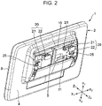
Fig. 2 is a perspective view of the vehicle-mounted device illustrated inFig. 1 as viewed from the front of the vehicle; -
Fig. 3 is a perspective view of the vehicle-mounted device illustrated inFig. 2 with a front cover removed; -
Fig. 4 is a partial exploded perspective view of a device base and a support member of the vehicle-mounted device illustrated inFig. 3 ; -
Fig. 5 is a partial cross-sectional view taken along line V-V ofFig. 4 when the support member is attached to the device base; -
Fig. 6 is a partial cross-sectional view of the device base taken along line VI-VI ofFig. 4 ; -
Fig. 7 is a partial cross-sectional view of a ruptured preferential rupture portion of the device base, which corresponds toFig. 5 ; -
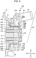
Fig. 8 is a partial cross-sectional view of a vehicle-mounted device according to a second embodiment of the present invention, which corresponds toFig. 5 ; and -
Fig. 9 illustrates a vehicle-mounted device according to a third embodiment of the present invention, which corresponds toFig. 5 . -
Figs. 1 to 7 illustrate a vehicle-mounteddevice 1 according to a first embodiment of the present invention. The vehicle-mounteddevice 1 is a vehicle-mounted display device. InFigs. 1 to 7 , a Z1 direction is the rearward direction opposite to the traveling direction of the vehicle, and the Z2 direction is a forward direction, which is the traveling direction of the vehicle. A Y1 direction is the upward direction, and a Y2 direction is the downward direction. As viewed from the front, an X1 direction is the left direction, and an X2 direction is the right direction. As illustrated inFigs. 2 and3 , the vehicle-mounteddevice 1 includes a devicemain body 2 and asupport member 20 for fixing the devicemain body 2 to a vehicle. - As illustrated in
Figs. 2 and3 , the devicemain body 2 has adevice base 10, which is part of the devicemain body 2. Thedevice base 10 is made by die casting using a light metal material, such as zinc or a zinc alloy. The surface of thedevice base 10 facing rearward (the Z1 direction) is a concave surface, and an electronic circuit board and a display cell are accommodated in thedevice base 10. The display cell is a color liquid crystal display cell or an electroluminescence display cell. The display screen of the display cell is directed rearward (the Z1 direction), and the rear surface (the Z1 direction) of the display cell is covered by a translucentdisplay cover panel 8. The front (the Z2 direction) of thedevice base 10 is covered by afront cover 4. Thefront cover 4 is made of a synthetic resin material or a light metal material. - Part of the
device base 10 is abase wall 11. Thebase wall 11 is a wall portion facing frontward (the Z2 direction) and having thedevice base 10 attached thereto. Thebase wall 11 has at least one of a flat wall surface and a curved wall surface. As illustrated inFigs. 2 and3 , thefront cover 4 has anopening 5 formed therein. Theopening 5 allows part of thebase wall 11 to be exposed to the front (the Z2 direction). - As illustrated in
Figs. 2 and3 , a pair ofsupport members 20 are attached to the surface of thebase wall 11 facing forward (the Z2 direction). The twosupport members 20 are located away from each other in the left-right direction (the X1-X2 direction). Thesupport member 20 includes afirst support member 21 and asecond support member 22. As illustrated inFigs. 4 and5 , thefirst support member 21 is screwed to thebase wall 11 of thedevice base 10. As illustrated inFig. 5 , asupport shaft 23 is fixed to thesecond support member 22 so as to extend in the left-right direction (the X1-X2 direction). Thesupport shaft 23 is fixed to thesecond support member 22 by aspline structure 24 so as to be rotatable together with thesecond support member 22. Thefirst support member 21 has arotation bearing portion 21a formed therein. Therotation bearing portion 21a is inserted into thesupport shaft 23 so as to be rotatable with rotational resistance. - As illustrated in
Figs. 1 and2 , thesecond support members 22 are located inside of theopening 5 of thefront cover 4 and protrude forward (the Z2 direction) from thefront cover 4. As illustrated inFig. 1 , thesecond support member 22 is fixed to a fixedbracket 29 by screwing. The fixedbracket 29 is fixed to the vehicle interior. For example, the fixedbracket 29 is fixed to the rear surface of the backrest portion of the front seat in the vehicle interior. Alternatively, the fixedbracket 29 is fixed to the ceiling portion of the vehicle interior. Still alternatively, the fixedbracket 29 is fixed to the dashboard or the internal structure portion of the instrument panel of the vehicle interior. Yet still alternatively, a movable member that goes in and out of a case may be provided in any part of the vehicle interior, and the fixedbracket 29 may be part of the movable member. -
Figs. 4 and5 illustrate thesupport member 20 located on the left side (an X1 side) ofFig. 3 and part of thebase wall 11. Thebase wall 11 has asupport fixing portion 12 formed thereon. Thesupport fixing portion 12 has afemale screw hole 12a formed therein. Thefemale screw hole 12a is used to attach thefirst support member 21 to thesupport fixing portion 12. In thebase wall 11, a region other than the left and rightsupport fixing portions 12, that is, a region surrounding thesupport fixing portion 12 is a basemain body portion 13. - As illustrated in
Figs. 4 and5 , in thebase wall 11, anupper hole portion 14 is formed at a boundary portion between the upper end portion of thesupport fixing portion 12 and the basemain body portion 13 so as to penetrate in the front-rear direction. In addition, alower hole portion 15 is formed at a boundary portion between the lower end portion of thesupport fixing portion 12 and the basemain body portion 13 so as to penetrate in the front-rear direction. Thebase wall 11 has smallconcave portions upper hole portion 14.Preferential rupture portions concave portions lower hole portion 15. As illustrated inFig. 6 , thepreferential rupture portions base wall 11 at the rear (the Z1 direction) so as to extend in the vertical direction. In a portion of thebase wall 11 that faces theopening 5 of thefront cover 4, a portion surrounded by theupper hole portion 14, thelower hole portion 15, and the left and rightpreferential rupture portions support fixing portion 12. The other region surrounding thesupport fixing portion 12 is the basemain body portion 13. Note that thepreferential rupture portion 16 may be thin-walled portions or grooves intermittently formed in the vertical direction. Alternatively, thepreferential rupture portion 16 may be a portion that has a thickness the same as the other portion and that has a plurality of long holes or round holes arranged at intervals in the vertical direction so as to penetrate in the front-rear direction. - As illustrated in
Figs. 4 and5 , thefirst support member 21 has a pair of fixingholes 21b formed therethrough. Fixing screws 25 are inserted into the fixingholes 21b and are screwed into thefemale screw holes 12a of thesupport fixing portion 12. In this manner, thedevice base 10 is fixed to thesupport member 20. Thesupport fixing portion 12 and thesupport member 20 fixed to thesupport fixing portion 12 constitute a rupture fixedportion 30. If thebase wall 11 ruptures at thepreferential rupture portion 16, the basemain body portion 13 of thedevice base 10 is separated from the rupture fixedportion 30. - As illustrated in
Figs. 4 and5 , the rupture fixedportion 30 has ahook member 35 attached thereto. Thehook member 35 is formed by bending a metal plate having elasticity (a spring property). For example, a spring stainless steel plate is used as the metal plate. Thehook member 35 has a fixedplate portion 36 andelastic pieces 37 located at either end of the fixedplate portion 36 in the vertical direction. Each of theelastic pieces 37 is bent rearward (the Z1 direction) from the fixedplate portion 36. In the top end of each of theelastic pieces 37, a hooking portion (a hooking piece) 39 is formed via a folded-back portion 38 so as to be directed forward (the Z2 direction). As illustrated inFig. 5 , as viewed from the side (the X1-X2 direction), the folded-back portion 38 is bent into a U shape (or V shape), and theelastic piece 37 and the hookingportion 39 face each other and extend forward (the Z2 direction). The inner angle between theelastic piece 37 and the hookingportion 39 is an acute angle. In addition, the fixedplate portion 36 has a pair of through-holes 36a formed therein. - An operation of attaching the
hook member 35 and thesupport member 20 to thedevice base 10 of the devicemain body 2 is described below. As illustrated inFigs. 4 and5 , in thesupport member 20, thesupport shaft 23 fixed to thesecond support member 22 is connected to therotation bearing portion 21a of thefirst support member 21 in a rotatable manner with a predetermined rotational resistance force. - As illustrated in
Fig. 3 , with thefront cover 4 removed from or attached to the devicemain body 2, the folded-back portion 38 of thehook member 35 is forcibly inserted rearward (the Z1 direction) into theupper hole portion 14 formed in the upper region of thesupport fixing portion 12 and thelower hole portion 15 formed in the lower region of thesupport fixing portion 12. Since thehook member 35 is formed with a metal plate having elasticity, the hookingportion 39 deforms so as to move closer to theelastic piece 37 inside each of theupper hole portion 14 and thelower hole portion 15. Thus, thehook member 35 is forcibly pushed rearward (in the Z1 direction). As illustrated inFig. 5 , when theelastic pieces 37 completely pass through theupper hole portion 14 and thelower hole portion 15, theelastic piece 37, the folded-back portion 38, and the hookingportion 39 return to their original shapes by the elastic restoring force of thehook member 35. As a result, afront end portion 39a of the hookingportion 39 is directed to aninner side portion 13a of the basemain body portion 13 of thedevice base 10 that faces the inner side of the device with a gap δ therebetween. Alternatively, thefront end portion 39a is in contact with theinner side portion 13a. - After the
hook member 35 is attached to thedevice base 10, thefirst support member 21 is placed in contact with the front surface of the fixedplate portion 36 of thehook member 35. Thereafter, the fixing screws 25 are inserted into the fixingholes 21b of thefirst support member 21 and the through-holes 36a formed in the fixedplate portions 36 and are screwed into thefemale screw holes 12a formed in thesupport fixing portion 12. If the fixing screws 25 are tightened, thehook member 35 is clamped between thesupport fixing portion 12 and thefirst support member 21 and, thus, thehook member 35 and thefirst support member 21 are fixed to thesupport fixing portion 12. - In the rupture fixed
portion 30, thehook member 35 is mounted on thedevice base 10 without falling off by simply inserting thehook member 35 into theupper hole portion 14 and thelower hole portion 15. Thereafter, thehook member 35 and thefirst support member 21 are fixed to thesupport fixing portion 12 with the same fixing screws 25. Since the operation of attaching only thehook member 35 is not required, the number of parts and the number of assembly steps can be reduced. - As illustrated in
Fig. 1 , the vehicle-mounteddevice 1 having thesupport member 20 attached to the front surface of thedevice base 10 is installed in the vehicle interior by screwing thesecond support member 22 to the fixedbracket 29. Since in thesupport member 20, thefirst support member 21 is rotatably supported by thesecond support member 22 using thesupport shaft 23 that acts as a fulcrum, a user can change the direction in which the display screen faces by holding and rotating the devicemain body 2 by hand. - If, for example, part of the human body hits the device
main body 2 of the vehicle-mounteddevice 1 due to a large impact that acts on the vehicle, a forward (Z2 direction) impact force acts on the devicemain body 2. In this case, in thebase wall 11 of thedevice base 10, stress concentrates on thepreferential rupture portions 16 located on either side of thesupport fixing portion 12 illustrated inFig. 6 . Thus, thebase wall 11 ruptures at thepreferential rupture portions 16 first. If the human body hits the devicemain body 2, an impact of the devicemain body 2 on, for example, the human body can be reduced since thedevice base 10 ruptures at thepreferential rupture portions 16. After thepreferential rupture portions 16 rupture, the basemain body portion 13 of thedevice base 10 is separated from the rupture fixedportion 30, and the devicemain body 2 is about to fall off from the rupture fixedportions 30. At this time, as illustrated inFig. 7 , thefront end portions portions hook member 35 are hooked to theinner side portions 13a of the basemain body portion 13 of thedevice base 10. Thus, the devicemain body 2 that remains after the rupture of thepreferential rupture portions 16 is prevented from falling off from the rupture fixedportion 30. - In the vehicle-mounted
device 1, thesupport fixing portion 12 and the basemain body portion 13 are provided in thebase wall 11 facing forward (in the forward direction of the device main body 2). For this reason, if thedevice base 10 ruptures at thepreferential rupture portions 16, a ruptured portion of thedevice base 10 does not protrude rearward (the Z1 direction) beyond the devicemain body 2, that is, towards a passenger. In this manner, the safety of the passenger can be ensured. - In the vehicle-mounted
device 1, thesupport fixing portion 12 and thepreferential rupture portions 16 are provided in thebase wall 11 of thedevice base 10, and thehook member 35 is in plane contact with thesupport fixing portion 12 and is fixed to thesupport fixing portion 12. Therefore, as illustrated inFig. 5 , an increase in the dimension in the front-rear direction due to thehook member 35 that is attached is equal to only the plate thickness of the fixedplate portion 36 of thehook member 35, and the depth of the device can be reduced. In addition, as illustrated inFig. 5 , when thepreferential rupture portion 16 does not rupture, thefront end portion 39a of the hookingportion 39 faces theinner side portion 13a of the basemain body portion 13 of thedevice base 10 with a small gap δ therebetween or without a gap (thefront end portion 39a is in contact with theinner side portion 13a). In this manner, when thepreferential rupture portion 16 ruptures, the devicemain body 2 is not considerably away from the rupture fixedportion 30 rearward (in the Z1 direction). Therefore, the devicemain body 2 does not hang down too long, and the possibility of the ruptured surface at thepreferential rupture portion 16 protruding rearward beyond the devicemain body 2 is further reduced. For example, it is desirable that the distance δ be set to a value less than or equal to a thickness T of the basemain body portion 13 at a portion which thefront end portion 39a of the hookingportion 39 is in contact with. - As illustrated in
Figs. 5 and7 , the pair ofelastic pieces hook member 35 extend inward of thedevice base 10 at a position at which thesupport fixing portion 12 is clamped vertically. Accordingly, if thepreferential rupture portions 16 rupture and, thus, thesupport fixing portion 12 separates from the basemain body portion 13, the basemain body portion 13 is supported by the upper and lower elastic pieces. Therefore, even when the rigidity of thehook member 35 is not excessively large, the devicemain body 2 can be sufficiently supported by the upper and lower hookingportions 39 so as not to be separated from the rupture fixedportion 30. In addition, thehook member 35 is formed with an elastic metal plate. For this reason, as illustrated inFig. 7 , if thepreferential rupture portions 16 rupture and, thus, the devicemain body 2 is about to fall by its own weight, the folded-back portion 38 and the hookingportion 39 of thehook member 35 elastically deform. In this manner, the drop impact of the devicemain body 2 can be reduced. - Furthermore, according to the
device base 10, as illustrated inFig. 4 , thesupport fixing portion 12 and the basemain body portion 13 are partitioned by anupper hole portion 14 and thelower hole portion 15 in the vertical direction (the Y1-Y2 direction). In addition, as illustrated inFig. 6 , thesupport fixing portion 12 and the basemain body portion 13 are partitioned by thepreferential rupture portions main body portion 13 and thesupport fixing portion 12 can be separated such that thesupport fixing portion 12 still retains a substantially rectangular shape. In addition, the smallconcave portions upper hole portion 14. Thepreferential rupture portions concave portions concave portions preferential rupture portions concave portions -
Fig. 8 illustrates part of a vehicle-mounteddevice 101 according to a second embodiment of the present invention.Fig. 9 illustrates part of a vehicle-mounteddevice 201 according to a third embodiment. The same reference numerals are used in the second and third embodiments to describe those members that are identical to the members of the vehicle-mounteddevice 1 according to the first embodiment illustrated inFigs. 1 to 7 , and detailed description of the members are not given. - According to the vehicle-mounted
device 101 of the second embodiment illustrated inFig. 8 , a fixinghole 12b is formed in thesupport fixing portion 12 that is part of thebase wall 11 of thedevice base 10, and afemale screw hole 21c is formed in thefirst support member 21. Ahook member 135 is formed with a metal plate. It is desirable that thehook member 135 be a metal plate having elasticity (a spring property), such as a stainless steel plate. Thehook member 135 has a through-hole 136a formed in a fixedplate portion 136 thereof. Thehook member 135 is mounted on the inner surface of thesupport fixing portion 12 from the inside of the devicemain body 2, and the fixingscrew 25 is inserted into the through-hole 136a of the fixedplate portion 136 and is further inserted into the fixinghole 12b of thesupport fixing portion 12. Thereafter, the fixingscrew 25 is screwed into thefemale screw hole 21c of thefirst support member 21. In this manner, thefirst support member 21 is fixed to thesupport fixing portion 12. In addition, a rupture fixedportion 30 having thehook member 135 attached thereto is formed. - The vehicle-mounted
device 101 is easy to assemble because thefirst support member 21 and thehook member 135 are fixed to thesupport fixing portion 12 with the same fixingscrew 25. At either end of thehook member 135 in the vertical direction, hooking portions (hooking pieces) 139 bent forward (in the Z2 direction) are formed. Afront end 139a of the hookingportion 139 faces theinner side portion 13a of the basemain body portion 13, or thefront end 139a is in contact with theinner side portion 13a. If an impact force of the devicemain body 2 is exerted in the vehicle-mounteddevice 101 illustrated inFig. 8 , thedevice base 10 ruptures at thepreferential rupture portion 16. Thereafter, thefront end 139a of the hookingportion 139 is brought into contact with theinner side portion 13a of the basemain body portion 13 and, thus, the devicemain body 2 can be prevented from falling off from the rupture fixedportion 30. - Like the vehicle-mounted
device 1 according to the first embodiment, in the vehicle-mounteddevice 201 according to the third embodiment illustrated inFig. 9 , thefirst support member 21 is fixed to thesupport fixing portion 12 of thedevice base 10 by the fixingscrew 25. Thus, the rupture fixedportion 30 is formed. Thefirst support member 21 has through-holes holes hook members 235 is formed with a metal plate. It is desirable that thehook member 235 be formed with a metal plate having elasticity (a spring property). Thehook members 235 are arranged in the vertical direction with thesupport fixing portion 12 therebetween. Note that the upper andlower hook members 235 may be separate members or may be connected into one body. Thehook member 235 has a fixedplate portion 236 and anelastic piece 237 integrally formed therein. Theelastic piece 237 is bent forward (the Z2 direction) from the fixedplate portion 236. At the front end of theelastic piece 237, a hooking portion (a hooking piece) 239 is formed via a folded-back portion 238. - The
hook member 235 is elastically deformed such that theelastic piece 237 and the hookingportion 239 move closer to each other. The folded-backportions 238 are inserted forward (the Z2 direction) into theupper hole portion 14 and thelower hole portion 15 of thedevice base 10 and are further inserted into the through-holes 21d of thefirst support member 21. When the hookingportion 239 completely passes through the through-hole 21d, the folded-back portion 238 returns to it's original shape by its elasticity. Thus, afront end portion 239a of the hookingportion 239 faces anouter side portion 21e of thefirst support member 21 which is the outer side portion of the rupture fixedportion 30, or the hookingportion 239 is in contact with theouter side portion 21e. In this mounted state, the fixedplate portion 236 is fixed to theinner side portion 13a of the basemain body portion 13 by a fixingscrew 240. Note that thefront end portion 239a of the hookingportion 239 may face or be in contact with the outer surface (the outer side portion) that faces frontward of thesupport fixing portion 12. - According to the vehicle-mounted
device 201 illustrated inFig. 9 , if thepreferential rupture portion 16 of thedevice base 10 ruptures and, thus, the devicemain body 2 is separated from the rupture fixedportion 30, the hookingportion 239 of thehook member 235 fixed to the basemain body portion 13 is hooked to theouter side portion 21e of thefirst support member 21 which is the outer side portion of the rupture fixedportion 30. In this manner, the devicemain body 2 can be prevented from falling down, and the rupture portion of thedevice base 10 can be prevented from protruding rearward (the Z1 direction) beyond the devicemain body 2. - In each of the above embodiments, the hooking
portions hook member 35, the hookingportions hook member 135, or the hookingportions hook member 235 are arranged in the vertical direction (the Y1-Y2 direction) with thesupport fixing portion 12 therebetween. However, the hook members may be arranged in the left-right direction (the X1-X2 direction) with thesupport fixing portion 12 therebetween. Alternatively, the hook member may have only one hooking portion. - Furthermore, according to the above embodiments, each of the vehicle-mounted
devices
Claims (8)
- A vehicle-mounted device (1) comprising:a device main body (2);a device base (10) that is part of the device main body (2); anda support member (20) configured to support the device base (10) on a vehicle side,characterized in thatthe device base (10) has, formed therein, a support fixing portion (12) to which the support member (20) is fixed, a base main body portion (13) other than the support fixing portion (12), and a preferential rupture portion (16) between the support fixing portion (12) and the base main body portion (13),the support fixing portion (12) and the support member (20) attached to the support fixing portion (12) constitute a rupture fixed portion (30), and the base main body portion (13) is separable from the rupture fixed portion (30) if the preferential rupture portion (16) ruptures, andone of the rupture fixed portion (30) and the base main body portion (13) is provided with a hook member (35), and the hook member (35) is provided with a hooking portion (39) that is hooked to the other when the base main body portion (13) separates from the rupture fixed portion (30).
- The vehicle-mounted device (1) according to Claim 1, wherein the device base (10) is provided with a base wall (11), and the support fixing portion (12) and the base main body portion (13) are part of the base wall (11).
- The vehicle-mounted device (1) according to Claim 1 or 2, wherein the hooking portion (39) of the hook member (35) is provided at least at two points that sandwich the support fixing portion (12).
- The vehicle-mounted device (1) according to any one of Claims 1 to 3, wherein the hook member (35) is attached to the rupture fixed portion (30), and the hooking portion (39) is hookable to an inner side portion (13a) of the base main body portion (13) facing an inside of the device main body (2).
- The vehicle-mounted device (1) according to Claim 4, wherein the hook member (35) is formed with a metal plate having elasticity, the metal plate has a folded-back portion (238), and a front end portion of the folded-back portion (238) serves as the hooking portion (39),wherein the device base (10) has a hole portion (14, 15) formed therein between the support fixing portion (12) and the base main body portion (13), andwherein the hook member (35) is elastically deformed and passes through the hole portion (14, 15) so that the hooking portion (39) is hookable to the inner side portion (13a) of the base main body portion (13).
- The vehicle-mounted device (1) according to Claim 4 or 5, wherein the support member (20) and the hook member (35) are attached to the support fixing portion (12) by using the same fixing screw.
- The vehicle-mounted device (1) according to any one of Claims 1 to 3, wherein the hook member (35) is attached to the base main body portion (13), and the hooking portion (39) is hookable to an outer side portion (21e) of the rupture fixed portion (30) facing the outside of the device main body (2).
- The vehicle-mounted device (1) according to Claim 7, wherein the hooking portion (39) is formed with a metal plate having elasticity.
Applications Claiming Priority (1)
| Application Number | Priority Date | Filing Date | Title |
|---|---|---|---|
| JP2019024163A JP7055575B2 (en) | 2019-02-14 | 2019-02-14 | In-vehicle equipment |
Publications (2)
| Publication Number | Publication Date |
|---|---|
| EP3696024A1 EP3696024A1 (en) | 2020-08-19 |
| EP3696024B1 true EP3696024B1 (en) | 2022-05-04 |
Family
ID=69593544
Family Applications (1)
| Application Number | Title | Priority Date | Filing Date |
|---|---|---|---|
| EP20155526.5A Active EP3696024B1 (en) | 2019-02-14 | 2020-02-05 | Vehicle-mounted device |
Country Status (4)
| Country | Link |
|---|---|
| US (1) | US10953812B2 (en) |
| EP (1) | EP3696024B1 (en) |
| JP (1) | JP7055575B2 (en) |
| CN (1) | CN111559319B (en) |
Families Citing this family (4)
| Publication number | Priority date | Publication date | Assignee | Title |
|---|---|---|---|---|
| JP7055575B2 (en) * | 2019-02-14 | 2022-04-18 | アルパイン株式会社 | In-vehicle equipment |
| US11292397B2 (en) * | 2020-07-30 | 2022-04-05 | Timothy White | Tablet holding assembly |
| CN114523907B (en) * | 2022-02-14 | 2023-02-14 | 深圳市百盛兴业科技有限公司 | Mobile intelligent terminal for driving safety |
| CN217197984U (en) | 2022-05-05 | 2022-08-16 | 东莞市云酷科技有限公司 | A double suction cup vehicle bracket fixing device |
Family Cites Families (30)
| Publication number | Priority date | Publication date | Assignee | Title |
|---|---|---|---|---|
| JP2001347895A (en) * | 2000-06-08 | 2001-12-18 | Nissan Shatai Co Ltd | Monitor mounting structure |
| JP4394312B2 (en) * | 2001-07-24 | 2010-01-06 | パナソニック株式会社 | In-vehicle display device |
| US6754070B2 (en) * | 2002-03-15 | 2004-06-22 | E-Lead Electronic Co., Ltd. | Car use computer |
| JP4139709B2 (en) * | 2003-03-05 | 2008-08-27 | パイオニア株式会社 | Electronics |
| JP4046066B2 (en) * | 2003-10-31 | 2008-02-13 | 株式会社デンソー | In-vehicle display device |
| US7388755B2 (en) * | 2004-02-11 | 2008-06-17 | E-Lead Electronic Co., Ltd. | Mechanical liquid crystal display device |
| US7201356B2 (en) * | 2004-05-07 | 2007-04-10 | Kai-Cheng Huang | Mounting apparatus of displayer suitable for external installation and inset installation |
| US7591045B2 (en) * | 2004-06-29 | 2009-09-22 | E-Lead Electronics Co., Ltd. | Buffer apparatus for a ceiling screen |
| JP4396492B2 (en) * | 2004-11-26 | 2010-01-13 | 豊田合成株式会社 | Airbag device for steering wheel |
| CN101258052B (en) * | 2005-09-21 | 2010-08-18 | 三菱电机株式会社 | Display opening and closing angle detection mechanism |
| DE102006025382B3 (en) * | 2006-05-31 | 2007-12-20 | Siemens Ag | Shutter device |
| DE102006025383B3 (en) * | 2006-05-31 | 2007-12-13 | Siemens Ag | Board monitor device |
| US20080040887A1 (en) * | 2006-08-16 | 2008-02-21 | Dickerson Harry L | Friction hinge for electronic apparatus |
| JP2008114808A (en) * | 2006-11-07 | 2008-05-22 | Toyota Motor Corp | Support structure of supported body |
| JP5308926B2 (en) * | 2009-06-10 | 2013-10-09 | 豊田鉄工株式会社 | Support structure for vehicle cooling unit |
| JP5594772B2 (en) * | 2010-09-29 | 2014-09-24 | 富士重工業株式会社 | Vehicle display device |
| US20160345045A1 (en) * | 2010-10-08 | 2016-11-24 | Calvin Liu | Vehicle display system |
| JP5790277B2 (en) * | 2011-08-08 | 2015-10-07 | トヨタ自動車株式会社 | Instrument panel structure |
| JP2013198330A (en) * | 2012-03-21 | 2013-09-30 | Keihin Corp | Support structure for equipment box of vehicle |
| JP5851945B2 (en) | 2012-06-21 | 2016-02-03 | アルパイン株式会社 | In-vehicle display device |
| DE102013003942A1 (en) * | 2013-03-07 | 2014-09-11 | Brose Fahrzeugteile Gmbh & Co. Kommanditgesellschaft, Coburg | Screen carrier for holding a screen in a vehicle |
| KR101481289B1 (en) * | 2013-07-05 | 2015-01-09 | 현대자동차주식회사 | Apparatus for operating avn monitor of vehicle |
| CN104854503B (en) * | 2013-10-29 | 2018-05-18 | 堺显示器制品株式会社 | Display device |
| DE102014212796A1 (en) * | 2014-07-02 | 2016-01-07 | Volkswagen Aktiengesellschaft | Arrangement for releasing and closing an opening in an interior trim part of a vehicle |
| JP6355566B2 (en) * | 2015-01-08 | 2018-07-11 | アルパイン株式会社 | In-vehicle display device |
| JP6355567B2 (en) | 2015-01-13 | 2018-07-11 | アルパイン株式会社 | In-vehicle display device |
| JP6359467B2 (en) * | 2015-01-14 | 2018-07-18 | アルパイン株式会社 | Liquid crystal display |
| US10525899B2 (en) * | 2018-06-08 | 2020-01-07 | Ford Global Technologies, Llc | Display screen assembly |
| JP7055575B2 (en) * | 2019-02-14 | 2022-04-18 | アルパイン株式会社 | In-vehicle equipment |
| US10946808B2 (en) * | 2019-02-14 | 2021-03-16 | Ford Global Technologies, Llc | Display screen mounting assembly |
-
2019
- 2019-02-14 JP JP2019024163A patent/JP7055575B2/en active Active
-
2020
- 2020-01-23 US US16/750,768 patent/US10953812B2/en active Active
- 2020-02-05 EP EP20155526.5A patent/EP3696024B1/en active Active
- 2020-02-14 CN CN202010091923.8A patent/CN111559319B/en active Active
Also Published As
| Publication number | Publication date |
|---|---|
| US20200262358A1 (en) | 2020-08-20 |
| JP2020131773A (en) | 2020-08-31 |
| US10953812B2 (en) | 2021-03-23 |
| CN111559319B (en) | 2023-11-24 |
| JP7055575B2 (en) | 2022-04-18 |
| CN111559319A (en) | 2020-08-21 |
| EP3696024A1 (en) | 2020-08-19 |
Similar Documents
| Publication | Publication Date | Title |
|---|---|---|
| EP3696024B1 (en) | Vehicle-mounted device | |
| EP3045340B1 (en) | On-vehicle display device | |
| CN103991367B (en) | The door structure of vehicle | |
| JP2013123005A (en) | Electronic device | |
| EP3466740A1 (en) | Fixing device for panel member | |
| JP6355566B2 (en) | In-vehicle display device | |
| EP2497993A2 (en) | Cabinet structure assembly | |
| CN103847641A (en) | Door mirror | |
| JP6458776B2 (en) | Vehicle display device | |
| WO2016075910A1 (en) | Vehicle-mounted-camera bracket | |
| EP2059036A1 (en) | Display | |
| JP2011228551A (en) | Pedestal and mold housing holding printed circuit board and communication device equipped with the same | |
| JP4394312B2 (en) | In-vehicle display device | |
| US20240081004A1 (en) | Display apparatus | |
| JP6365071B2 (en) | Display device | |
| JP7682020B2 (en) | Electronic Indicating Instrument | |
| JP6413948B2 (en) | Display device | |
| JP2019050289A (en) | Fixing member | |
| JP6292596B2 (en) | Game machine | |
| JP6090952B1 (en) | Game machine | |
| JP6657026B2 (en) | Vehicle fixture | |
| JP2006205969A (en) | Metering device for vehicle | |
| KR200484536Y1 (en) | car driver's contact information display panels | |
| JP2008265372A (en) | Instrument panel structure | |
| JP2009259954A (en) | Drip-proof structure of circuit board |
Legal Events
| Date | Code | Title | Description |
|---|---|---|---|
| PUAI | Public reference made under article 153(3) epc to a published international application that has entered the european phase |
Free format text: ORIGINAL CODE: 0009012 |
|
| STAA | Information on the status of an ep patent application or granted ep patent |
Free format text: STATUS: THE APPLICATION HAS BEEN PUBLISHED |
|
| AK | Designated contracting states |
Kind code of ref document: A1 Designated state(s): AL AT BE BG CH CY CZ DE DK EE ES FI FR GB GR HR HU IE IS IT LI LT LU LV MC MK MT NL NO PL PT RO RS SE SI SK SM TR |
|
| AX | Request for extension of the european patent |
Extension state: BA ME |
|
| STAA | Information on the status of an ep patent application or granted ep patent |
Free format text: STATUS: REQUEST FOR EXAMINATION WAS MADE |
|
| 17P | Request for examination filed |
Effective date: 20210112 |
|
| RBV | Designated contracting states (corrected) |
Designated state(s): AL AT BE BG CH CY CZ DE DK EE ES FI FR GB GR HR HU IE IS IT LI LT LU LV MC MK MT NL NO PL PT RO RS SE SI SK SM TR |
|
| GRAP | Despatch of communication of intention to grant a patent |
Free format text: ORIGINAL CODE: EPIDOSNIGR1 |
|
| STAA | Information on the status of an ep patent application or granted ep patent |
Free format text: STATUS: GRANT OF PATENT IS INTENDED |
|
| INTG | Intention to grant announced |
Effective date: 20210907 |
|
| GRAS | Grant fee paid |
Free format text: ORIGINAL CODE: EPIDOSNIGR3 |
|
| GRAA | (expected) grant |
Free format text: ORIGINAL CODE: 0009210 |
|
| STAA | Information on the status of an ep patent application or granted ep patent |
Free format text: STATUS: THE PATENT HAS BEEN GRANTED |
|
| AK | Designated contracting states |
Kind code of ref document: B1 Designated state(s): AL AT BE BG CH CY CZ DE DK EE ES FI FR GB GR HR HU IE IS IT LI LT LU LV MC MK MT NL NO PL PT RO RS SE SI SK SM TR |
|
| REG | Reference to a national code |
Ref country code: GB Ref legal event code: FG4D |
|
| REG | Reference to a national code |
Ref country code: CH Ref legal event code: EP |
|
| REG | Reference to a national code |
Ref country code: AT Ref legal event code: REF Ref document number: 1488733 Country of ref document: AT Kind code of ref document: T Effective date: 20220515 |
|
| REG | Reference to a national code |
Ref country code: DE Ref legal event code: R096 Ref document number: 602020002886 Country of ref document: DE |
|
| REG | Reference to a national code |
Ref country code: IE Ref legal event code: FG4D |
|
| REG | Reference to a national code |
Ref country code: LT Ref legal event code: MG9D |
|
| REG | Reference to a national code |
Ref country code: NL Ref legal event code: MP Effective date: 20220504 |
|
| REG | Reference to a national code |
Ref country code: AT Ref legal event code: MK05 Ref document number: 1488733 Country of ref document: AT Kind code of ref document: T Effective date: 20220504 |
|
| PG25 | Lapsed in a contracting state [announced via postgrant information from national office to epo] |
Ref country code: SE Free format text: LAPSE BECAUSE OF FAILURE TO SUBMIT A TRANSLATION OF THE DESCRIPTION OR TO PAY THE FEE WITHIN THE PRESCRIBED TIME-LIMIT Effective date: 20220504 Ref country code: PT Free format text: LAPSE BECAUSE OF FAILURE TO SUBMIT A TRANSLATION OF THE DESCRIPTION OR TO PAY THE FEE WITHIN THE PRESCRIBED TIME-LIMIT Effective date: 20220905 Ref country code: NO Free format text: LAPSE BECAUSE OF FAILURE TO SUBMIT A TRANSLATION OF THE DESCRIPTION OR TO PAY THE FEE WITHIN THE PRESCRIBED TIME-LIMIT Effective date: 20220804 Ref country code: NL Free format text: LAPSE BECAUSE OF FAILURE TO SUBMIT A TRANSLATION OF THE DESCRIPTION OR TO PAY THE FEE WITHIN THE PRESCRIBED TIME-LIMIT Effective date: 20220504 Ref country code: LT Free format text: LAPSE BECAUSE OF FAILURE TO SUBMIT A TRANSLATION OF THE DESCRIPTION OR TO PAY THE FEE WITHIN THE PRESCRIBED TIME-LIMIT Effective date: 20220504 Ref country code: HR Free format text: LAPSE BECAUSE OF FAILURE TO SUBMIT A TRANSLATION OF THE DESCRIPTION OR TO PAY THE FEE WITHIN THE PRESCRIBED TIME-LIMIT Effective date: 20220504 Ref country code: GR Free format text: LAPSE BECAUSE OF FAILURE TO SUBMIT A TRANSLATION OF THE DESCRIPTION OR TO PAY THE FEE WITHIN THE PRESCRIBED TIME-LIMIT Effective date: 20220805 Ref country code: FI Free format text: LAPSE BECAUSE OF FAILURE TO SUBMIT A TRANSLATION OF THE DESCRIPTION OR TO PAY THE FEE WITHIN THE PRESCRIBED TIME-LIMIT Effective date: 20220504 Ref country code: ES Free format text: LAPSE BECAUSE OF FAILURE TO SUBMIT A TRANSLATION OF THE DESCRIPTION OR TO PAY THE FEE WITHIN THE PRESCRIBED TIME-LIMIT Effective date: 20220504 Ref country code: BG Free format text: LAPSE BECAUSE OF FAILURE TO SUBMIT A TRANSLATION OF THE DESCRIPTION OR TO PAY THE FEE WITHIN THE PRESCRIBED TIME-LIMIT Effective date: 20220804 Ref country code: AT Free format text: LAPSE BECAUSE OF FAILURE TO SUBMIT A TRANSLATION OF THE DESCRIPTION OR TO PAY THE FEE WITHIN THE PRESCRIBED TIME-LIMIT Effective date: 20220504 |
|
| PG25 | Lapsed in a contracting state [announced via postgrant information from national office to epo] |
Ref country code: RS Free format text: LAPSE BECAUSE OF FAILURE TO SUBMIT A TRANSLATION OF THE DESCRIPTION OR TO PAY THE FEE WITHIN THE PRESCRIBED TIME-LIMIT Effective date: 20220504 Ref country code: PL Free format text: LAPSE BECAUSE OF FAILURE TO SUBMIT A TRANSLATION OF THE DESCRIPTION OR TO PAY THE FEE WITHIN THE PRESCRIBED TIME-LIMIT Effective date: 20220504 Ref country code: LV Free format text: LAPSE BECAUSE OF FAILURE TO SUBMIT A TRANSLATION OF THE DESCRIPTION OR TO PAY THE FEE WITHIN THE PRESCRIBED TIME-LIMIT Effective date: 20220504 Ref country code: IS Free format text: LAPSE BECAUSE OF FAILURE TO SUBMIT A TRANSLATION OF THE DESCRIPTION OR TO PAY THE FEE WITHIN THE PRESCRIBED TIME-LIMIT Effective date: 20220904 |
|
| PG25 | Lapsed in a contracting state [announced via postgrant information from national office to epo] |
Ref country code: SM Free format text: LAPSE BECAUSE OF FAILURE TO SUBMIT A TRANSLATION OF THE DESCRIPTION OR TO PAY THE FEE WITHIN THE PRESCRIBED TIME-LIMIT Effective date: 20220504 Ref country code: SK Free format text: LAPSE BECAUSE OF FAILURE TO SUBMIT A TRANSLATION OF THE DESCRIPTION OR TO PAY THE FEE WITHIN THE PRESCRIBED TIME-LIMIT Effective date: 20220504 Ref country code: RO Free format text: LAPSE BECAUSE OF FAILURE TO SUBMIT A TRANSLATION OF THE DESCRIPTION OR TO PAY THE FEE WITHIN THE PRESCRIBED TIME-LIMIT Effective date: 20220504 Ref country code: EE Free format text: LAPSE BECAUSE OF FAILURE TO SUBMIT A TRANSLATION OF THE DESCRIPTION OR TO PAY THE FEE WITHIN THE PRESCRIBED TIME-LIMIT Effective date: 20220504 Ref country code: DK Free format text: LAPSE BECAUSE OF FAILURE TO SUBMIT A TRANSLATION OF THE DESCRIPTION OR TO PAY THE FEE WITHIN THE PRESCRIBED TIME-LIMIT Effective date: 20220504 Ref country code: CZ Free format text: LAPSE BECAUSE OF FAILURE TO SUBMIT A TRANSLATION OF THE DESCRIPTION OR TO PAY THE FEE WITHIN THE PRESCRIBED TIME-LIMIT Effective date: 20220504 |
|
| REG | Reference to a national code |
Ref country code: DE Ref legal event code: R097 Ref document number: 602020002886 Country of ref document: DE |
|
| PLBE | No opposition filed within time limit |
Free format text: ORIGINAL CODE: 0009261 |
|
| STAA | Information on the status of an ep patent application or granted ep patent |
Free format text: STATUS: NO OPPOSITION FILED WITHIN TIME LIMIT |
|
| PG25 | Lapsed in a contracting state [announced via postgrant information from national office to epo] |
Ref country code: AL Free format text: LAPSE BECAUSE OF FAILURE TO SUBMIT A TRANSLATION OF THE DESCRIPTION OR TO PAY THE FEE WITHIN THE PRESCRIBED TIME-LIMIT Effective date: 20220504 |
|
| 26N | No opposition filed |
Effective date: 20230207 |
|
| PG25 | Lapsed in a contracting state [announced via postgrant information from national office to epo] |
Ref country code: SI Free format text: LAPSE BECAUSE OF FAILURE TO SUBMIT A TRANSLATION OF THE DESCRIPTION OR TO PAY THE FEE WITHIN THE PRESCRIBED TIME-LIMIT Effective date: 20220504 |
|
| PG25 | Lapsed in a contracting state [announced via postgrant information from national office to epo] |
Ref country code: MC Free format text: LAPSE BECAUSE OF FAILURE TO SUBMIT A TRANSLATION OF THE DESCRIPTION OR TO PAY THE FEE WITHIN THE PRESCRIBED TIME-LIMIT Effective date: 20220504 |
|
| REG | Reference to a national code |
Ref country code: CH Ref legal event code: PL |
|
| REG | Reference to a national code |
Ref country code: BE Ref legal event code: MM Effective date: 20230228 |
|
| PG25 | Lapsed in a contracting state [announced via postgrant information from national office to epo] |
Ref country code: LU Free format text: LAPSE BECAUSE OF NON-PAYMENT OF DUE FEES Effective date: 20230205 Ref country code: LI Free format text: LAPSE BECAUSE OF NON-PAYMENT OF DUE FEES Effective date: 20230228 Ref country code: CH Free format text: LAPSE BECAUSE OF NON-PAYMENT OF DUE FEES Effective date: 20230228 |
|
| REG | Reference to a national code |
Ref country code: IE Ref legal event code: MM4A |
|
| PG25 | Lapsed in a contracting state [announced via postgrant information from national office to epo] |
Ref country code: IT Free format text: LAPSE BECAUSE OF FAILURE TO SUBMIT A TRANSLATION OF THE DESCRIPTION OR TO PAY THE FEE WITHIN THE PRESCRIBED TIME-LIMIT Effective date: 20220504 Ref country code: IE Free format text: LAPSE BECAUSE OF NON-PAYMENT OF DUE FEES Effective date: 20230205 |
|
| PG25 | Lapsed in a contracting state [announced via postgrant information from national office to epo] |
Ref country code: BE Free format text: LAPSE BECAUSE OF NON-PAYMENT OF DUE FEES Effective date: 20230228 |
|
| PG25 | Lapsed in a contracting state [announced via postgrant information from national office to epo] |
Ref country code: BG Free format text: LAPSE BECAUSE OF FAILURE TO SUBMIT A TRANSLATION OF THE DESCRIPTION OR TO PAY THE FEE WITHIN THE PRESCRIBED TIME-LIMIT Effective date: 20220504 |
|
| PG25 | Lapsed in a contracting state [announced via postgrant information from national office to epo] |
Ref country code: BG Free format text: LAPSE BECAUSE OF FAILURE TO SUBMIT A TRANSLATION OF THE DESCRIPTION OR TO PAY THE FEE WITHIN THE PRESCRIBED TIME-LIMIT Effective date: 20220504 |
|
| PG25 | Lapsed in a contracting state [announced via postgrant information from national office to epo] |
Ref country code: CY Free format text: LAPSE BECAUSE OF FAILURE TO SUBMIT A TRANSLATION OF THE DESCRIPTION OR TO PAY THE FEE WITHIN THE PRESCRIBED TIME-LIMIT; INVALID AB INITIO Effective date: 20200205 |
|
| PG25 | Lapsed in a contracting state [announced via postgrant information from national office to epo] |
Ref country code: HU Free format text: LAPSE BECAUSE OF FAILURE TO SUBMIT A TRANSLATION OF THE DESCRIPTION OR TO PAY THE FEE WITHIN THE PRESCRIBED TIME-LIMIT; INVALID AB INITIO Effective date: 20200205 |
|
| PG25 | Lapsed in a contracting state [announced via postgrant information from national office to epo] |
Ref country code: TR Free format text: LAPSE BECAUSE OF FAILURE TO SUBMIT A TRANSLATION OF THE DESCRIPTION OR TO PAY THE FEE WITHIN THE PRESCRIBED TIME-LIMIT Effective date: 20220504 |
|
| PGFP | Annual fee paid to national office [announced via postgrant information from national office to epo] |
Ref country code: GB Payment date: 20260220 Year of fee payment: 7 |
|
| PGFP | Annual fee paid to national office [announced via postgrant information from national office to epo] |
Ref country code: DE Payment date: 20260218 Year of fee payment: 7 |
|
| PGFP | Annual fee paid to national office [announced via postgrant information from national office to epo] |
Ref country code: FR Payment date: 20260218 Year of fee payment: 7 |