EP3696011A2 - Charging system and method of a battery of an electric vehicle - Google Patents
Charging system and method of a battery of an electric vehicle Download PDFInfo
- Publication number
- EP3696011A2 EP3696011A2 EP20156452.3A EP20156452A EP3696011A2 EP 3696011 A2 EP3696011 A2 EP 3696011A2 EP 20156452 A EP20156452 A EP 20156452A EP 3696011 A2 EP3696011 A2 EP 3696011A2
- Authority
- EP
- European Patent Office
- Prior art keywords
- charging
- cable
- battery
- connector
- authentication
- Prior art date
- Legal status (The legal status is an assumption and is not a legal conclusion. Google has not performed a legal analysis and makes no representation as to the accuracy of the status listed.)
- Granted
Links
- 238000000034 method Methods 0.000 title claims abstract description 24
- 230000005405 multipole Effects 0.000 claims description 40
- 238000004891 communication Methods 0.000 claims description 9
- 230000007246 mechanism Effects 0.000 claims description 8
- 230000004044 response Effects 0.000 claims description 5
- 238000004519 manufacturing process Methods 0.000 claims description 4
- 230000001105 regulatory effect Effects 0.000 claims description 3
- 230000008569 process Effects 0.000 claims description 2
- 101100165827 Mus musculus Cables1 gene Proteins 0.000 description 21
- 230000006870 function Effects 0.000 description 6
- 230000004913 activation Effects 0.000 description 3
- 238000005516 engineering process Methods 0.000 description 3
- 230000003213 activating effect Effects 0.000 description 2
- 238000013475 authorization Methods 0.000 description 2
- 230000004224 protection Effects 0.000 description 2
- 230000006978 adaptation Effects 0.000 description 1
- 230000005540 biological transmission Effects 0.000 description 1
- 238000010367 cloning Methods 0.000 description 1
- 230000002860 competitive effect Effects 0.000 description 1
- 230000001143 conditioned effect Effects 0.000 description 1
- 230000001276 controlling effect Effects 0.000 description 1
- 230000001419 dependent effect Effects 0.000 description 1
- 238000010586 diagram Methods 0.000 description 1
- 238000009792 diffusion process Methods 0.000 description 1
- 230000000694 effects Effects 0.000 description 1
- 238000009434 installation Methods 0.000 description 1
- 230000003993 interaction Effects 0.000 description 1
- 230000007257 malfunction Effects 0.000 description 1
- 230000007480 spreading Effects 0.000 description 1
- 230000001360 synchronised effect Effects 0.000 description 1
Images


Classifications
-
- B—PERFORMING OPERATIONS; TRANSPORTING
- B60—VEHICLES IN GENERAL
- B60L—PROPULSION OF ELECTRICALLY-PROPELLED VEHICLES; SUPPLYING ELECTRIC POWER FOR AUXILIARY EQUIPMENT OF ELECTRICALLY-PROPELLED VEHICLES; ELECTRODYNAMIC BRAKE SYSTEMS FOR VEHICLES IN GENERAL; MAGNETIC SUSPENSION OR LEVITATION FOR VEHICLES; MONITORING OPERATING VARIABLES OF ELECTRICALLY-PROPELLED VEHICLES; ELECTRIC SAFETY DEVICES FOR ELECTRICALLY-PROPELLED VEHICLES
- B60L53/00—Methods of charging batteries, specially adapted for electric vehicles; Charging stations or on-board charging equipment therefor; Exchange of energy storage elements in electric vehicles
- B60L53/10—Methods of charging batteries, specially adapted for electric vehicles; Charging stations or on-board charging equipment therefor; Exchange of energy storage elements in electric vehicles characterised by the energy transfer between the charging station and the vehicle
- B60L53/14—Conductive energy transfer
- B60L53/18—Cables specially adapted for charging electric vehicles
-
- B—PERFORMING OPERATIONS; TRANSPORTING
- B60—VEHICLES IN GENERAL
- B60L—PROPULSION OF ELECTRICALLY-PROPELLED VEHICLES; SUPPLYING ELECTRIC POWER FOR AUXILIARY EQUIPMENT OF ELECTRICALLY-PROPELLED VEHICLES; ELECTRODYNAMIC BRAKE SYSTEMS FOR VEHICLES IN GENERAL; MAGNETIC SUSPENSION OR LEVITATION FOR VEHICLES; MONITORING OPERATING VARIABLES OF ELECTRICALLY-PROPELLED VEHICLES; ELECTRIC SAFETY DEVICES FOR ELECTRICALLY-PROPELLED VEHICLES
- B60L50/00—Electric propulsion with power supplied within the vehicle
- B60L50/20—Electric propulsion with power supplied within the vehicle using propulsion power generated by humans or animals
-
- B—PERFORMING OPERATIONS; TRANSPORTING
- B60—VEHICLES IN GENERAL
- B60L—PROPULSION OF ELECTRICALLY-PROPELLED VEHICLES; SUPPLYING ELECTRIC POWER FOR AUXILIARY EQUIPMENT OF ELECTRICALLY-PROPELLED VEHICLES; ELECTRODYNAMIC BRAKE SYSTEMS FOR VEHICLES IN GENERAL; MAGNETIC SUSPENSION OR LEVITATION FOR VEHICLES; MONITORING OPERATING VARIABLES OF ELECTRICALLY-PROPELLED VEHICLES; ELECTRIC SAFETY DEVICES FOR ELECTRICALLY-PROPELLED VEHICLES
- B60L53/00—Methods of charging batteries, specially adapted for electric vehicles; Charging stations or on-board charging equipment therefor; Exchange of energy storage elements in electric vehicles
- B60L53/10—Methods of charging batteries, specially adapted for electric vehicles; Charging stations or on-board charging equipment therefor; Exchange of energy storage elements in electric vehicles characterised by the energy transfer between the charging station and the vehicle
- B60L53/14—Conductive energy transfer
- B60L53/16—Connectors, e.g. plugs or sockets, specially adapted for charging electric vehicles
-
- B—PERFORMING OPERATIONS; TRANSPORTING
- B60—VEHICLES IN GENERAL
- B60L—PROPULSION OF ELECTRICALLY-PROPELLED VEHICLES; SUPPLYING ELECTRIC POWER FOR AUXILIARY EQUIPMENT OF ELECTRICALLY-PROPELLED VEHICLES; ELECTRODYNAMIC BRAKE SYSTEMS FOR VEHICLES IN GENERAL; MAGNETIC SUSPENSION OR LEVITATION FOR VEHICLES; MONITORING OPERATING VARIABLES OF ELECTRICALLY-PROPELLED VEHICLES; ELECTRIC SAFETY DEVICES FOR ELECTRICALLY-PROPELLED VEHICLES
- B60L2200/00—Type of vehicles
- B60L2200/12—Bikes
-
- B—PERFORMING OPERATIONS; TRANSPORTING
- B60—VEHICLES IN GENERAL
- B60L—PROPULSION OF ELECTRICALLY-PROPELLED VEHICLES; SUPPLYING ELECTRIC POWER FOR AUXILIARY EQUIPMENT OF ELECTRICALLY-PROPELLED VEHICLES; ELECTRODYNAMIC BRAKE SYSTEMS FOR VEHICLES IN GENERAL; MAGNETIC SUSPENSION OR LEVITATION FOR VEHICLES; MONITORING OPERATING VARIABLES OF ELECTRICALLY-PROPELLED VEHICLES; ELECTRIC SAFETY DEVICES FOR ELECTRICALLY-PROPELLED VEHICLES
- B60L2250/00—Driver interactions
- B60L2250/20—Driver interactions by driver identification
-
- B—PERFORMING OPERATIONS; TRANSPORTING
- B60—VEHICLES IN GENERAL
- B60L—PROPULSION OF ELECTRICALLY-PROPELLED VEHICLES; SUPPLYING ELECTRIC POWER FOR AUXILIARY EQUIPMENT OF ELECTRICALLY-PROPELLED VEHICLES; ELECTRODYNAMIC BRAKE SYSTEMS FOR VEHICLES IN GENERAL; MAGNETIC SUSPENSION OR LEVITATION FOR VEHICLES; MONITORING OPERATING VARIABLES OF ELECTRICALLY-PROPELLED VEHICLES; ELECTRIC SAFETY DEVICES FOR ELECTRICALLY-PROPELLED VEHICLES
- B60L2270/00—Problem solutions or means not otherwise provided for
- B60L2270/30—Preventing theft during charging
- B60L2270/34—Preventing theft during charging of parts
-
- Y—GENERAL TAGGING OF NEW TECHNOLOGICAL DEVELOPMENTS; GENERAL TAGGING OF CROSS-SECTIONAL TECHNOLOGIES SPANNING OVER SEVERAL SECTIONS OF THE IPC; TECHNICAL SUBJECTS COVERED BY FORMER USPC CROSS-REFERENCE ART COLLECTIONS [XRACs] AND DIGESTS
- Y02—TECHNOLOGIES OR APPLICATIONS FOR MITIGATION OR ADAPTATION AGAINST CLIMATE CHANGE
- Y02T—CLIMATE CHANGE MITIGATION TECHNOLOGIES RELATED TO TRANSPORTATION
- Y02T10/00—Road transport of goods or passengers
- Y02T10/60—Other road transportation technologies with climate change mitigation effect
- Y02T10/70—Energy storage systems for electromobility, e.g. batteries
-
- Y—GENERAL TAGGING OF NEW TECHNOLOGICAL DEVELOPMENTS; GENERAL TAGGING OF CROSS-SECTIONAL TECHNOLOGIES SPANNING OVER SEVERAL SECTIONS OF THE IPC; TECHNICAL SUBJECTS COVERED BY FORMER USPC CROSS-REFERENCE ART COLLECTIONS [XRACs] AND DIGESTS
- Y02—TECHNOLOGIES OR APPLICATIONS FOR MITIGATION OR ADAPTATION AGAINST CLIMATE CHANGE
- Y02T—CLIMATE CHANGE MITIGATION TECHNOLOGIES RELATED TO TRANSPORTATION
- Y02T10/00—Road transport of goods or passengers
- Y02T10/60—Other road transportation technologies with climate change mitigation effect
- Y02T10/7072—Electromobility specific charging systems or methods for batteries, ultracapacitors, supercapacitors or double-layer capacitors
-
- Y—GENERAL TAGGING OF NEW TECHNOLOGICAL DEVELOPMENTS; GENERAL TAGGING OF CROSS-SECTIONAL TECHNOLOGIES SPANNING OVER SEVERAL SECTIONS OF THE IPC; TECHNICAL SUBJECTS COVERED BY FORMER USPC CROSS-REFERENCE ART COLLECTIONS [XRACs] AND DIGESTS
- Y02—TECHNOLOGIES OR APPLICATIONS FOR MITIGATION OR ADAPTATION AGAINST CLIMATE CHANGE
- Y02T—CLIMATE CHANGE MITIGATION TECHNOLOGIES RELATED TO TRANSPORTATION
- Y02T90/00—Enabling technologies or technologies with a potential or indirect contribution to GHG emissions mitigation
- Y02T90/10—Technologies relating to charging of electric vehicles
- Y02T90/14—Plug-in electric vehicles
-
- Y—GENERAL TAGGING OF NEW TECHNOLOGICAL DEVELOPMENTS; GENERAL TAGGING OF CROSS-SECTIONAL TECHNOLOGIES SPANNING OVER SEVERAL SECTIONS OF THE IPC; TECHNICAL SUBJECTS COVERED BY FORMER USPC CROSS-REFERENCE ART COLLECTIONS [XRACs] AND DIGESTS
- Y04—INFORMATION OR COMMUNICATION TECHNOLOGIES HAVING AN IMPACT ON OTHER TECHNOLOGY AREAS
- Y04S—SYSTEMS INTEGRATING TECHNOLOGIES RELATED TO POWER NETWORK OPERATION, COMMUNICATION OR INFORMATION TECHNOLOGIES FOR IMPROVING THE ELECTRICAL POWER GENERATION, TRANSMISSION, DISTRIBUTION, MANAGEMENT OR USAGE, i.e. SMART GRIDS
- Y04S30/00—Systems supporting specific end-user applications in the sector of transportation
- Y04S30/10—Systems supporting the interoperability of electric or hybrid vehicles
- Y04S30/14—Details associated with the interoperability, e.g. vehicle recognition, authentication, identification or billing
Definitions
- the present invention relates to a charging system and method of the battery of electric vehicles, in particular of electric bicycles or pedal-assisted vehicles.
- batteries may differ from one another for a different supply voltage, typically 36 V or 48 V.
- Patent application EP 2583859 A2 aims to solve the problem of different supply voltages by providing the charging cables with an electronic identification device, e.g. an RFID tag, a barcode or a QR-code, which contains information about the supply voltage, and the charging station with an electronic reading device capable of receiving the information contained in the electronic identification device and of communicating which supply voltage is to be used to a control unit of the charging station.
- an electronic identification device e.g. an RFID tag, a barcode or a QR-code
- a non-conforming cable may not only be dangerous but may also cause damage to both the charging station and the battery to be charged.
- the charging system of a battery of an electric vehicle comprises a charging station and at least one charging cable connectable to a battery to be charged.
- the charging station comprises at least one power unit provided with a power card adapted to charge the battery and with a female-type connector adapted to connect to a male-type connector of the charging cable.
- the charging cable and the charging station are provided with respective authentication circuits configured to implement a cable authentication algorithm which, in case of positive outcome, enables charging the battery.
- a unique cable identifier code is stored in the cable authentication circuit; the authentication circuit of the charging station is configured to read this unique cable identifier code.
- the charging method which uses the aforesaid charging system provides checking whether the cable is authentic by means of an authentication procedure run by the cable authentication circuits on the cable and on the charging station when the cable is connected to the charging station.
- the battery charging is subject to checking whether a user is enabled to use the charging service.
- a check is performed by means of a user identification procedure which comprises the steps of:
- the two tokens coincide, it means that the user is enabled to request the service and therefore the power supply to the battery is activated, or the cable authentication procedure is activated which, if the outcome is positive, enables the delivery of the service.
- the unique cable identification token (CTID) and the unique user identifier code (UID) are transmitted in a wireless manner by the user to the charging station via an app residing on a portable electronic device of the user, e.g. a smartphone.
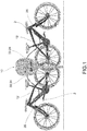
- the charging system 1 comprises a charging station 10 and at least one charging cable 12, which is connnectable to a battery 2 to be charged, e.g. the battery or accumulator of an electric or pedal-assisted bicycle.
- the charging station 1 may be a public station installed near roads, parking lots, public buildings, etc.
- the charging cable 12 connects the charging station 10 to the battery to be charged.
- the charging system 10 comprises a power supply unit 14 adapted to generate at least one battery supply voltage.
- the battery supply voltage generated by the power supply unit 14 is thus adapted to charge the battery 2 at the working voltage expected for the battery 2.
- the charging system 10 further comprises a service power unit 16 adapted to generate at service voltage. Such a service voltage is not used to supply the battery but to supply further electronic devices of the charging station 10, as described below.
- the service power unit 16 may be separated from the power supply unit 14 or can be made inside the power supply unit 14.
- the charging station 10 is managed by a control unit 18 which is operatively connected to the power supply unit 14 and the service supply unit 16.
- the control unit 18 is supplied by the operating voltage.
- the charging station 10 further comprises a regulator 20 connected to the control unit 18 and adapted to supply a regulated charging current to the battery 2 to be recharged.
- the charging station 10 For connecting to the charging cable 12, the charging station 10 is provided with at least one female-type multipole charging connector 22, i.e. an electric socket.
- This multipole charging connector 22 comprises:
- the charging cable 12 comprises a first male-type multipole cable connector 24 adapted to be connected to the multipole charging connector 22, and, at the opposite end of the cable, a second multipole cable connector 26 connectable to the battery 2.
- the second cable connector 26 is configured to connect to the connector on the battery 2 to be charged.
- the first multipole cable connector 24 comprises:
- the second multipole cable connector 26 has a number of poles which depends on the type of battery 2 to be charged. In particular, for batteries of the first type, i.e. which allow charging as soon as current is supplied to the terminals of the charging cable, the second multipole cable connector 26 can have only two poles (positive and negative pole); for the second type of battery, i.e. which requires to be queried by a control signal to connect the battery poles to the charging cable, in addition to the positive and negative poles there will be a third pole for the control signal (as in the example shown in figure 2 ).
- control unit 18 it is provided with a connected connector check circuit 28, operatively connected to the logic input C of the multipole charging connector 22 and adapted to detect whether the logic input C is at the voltage present on the negative pole of the battery 2. In the affirmative case, it means that charging cable 12 is correctly connected both to the battery 2 to be charged and to the charging connector 22.
- the control unit 18 is also provided with a battery enabling circuit 30 adapted to provide an enabling signal to the digital logic output D adapted to allow the connection of one of the battery poles, e.g. the positive pole, to the corresponding terminal of the charging cable, e.g. the positive terminal B'.
- a battery enabling circuit 30 adapted to provide an enabling signal to the digital logic output D adapted to allow the connection of one of the battery poles, e.g. the positive pole, to the corresponding terminal of the charging cable, e.g. the positive terminal B'.
- the control unit 18 has a further voltage presence input I connected to the positive terminal B of the multipole charging connector 22.
- this voltage presence input is at a zero logic value; if a battery of the second type is connected, in reply to the reception of the enabling signal D, the battery 2 enables the transmission of its own voltage level on the positive pole B' of the male multipole cable connector 24, and thus on the voltage presence input I.
- the internal protections with which it is provided do not allow the charging cable to read the voltage at the ends of the battery and the voltage presence input I remains at zero logic value.
- the charging system 10 comprises a switch device 44, e.g. a relay, between the regulator 20 and the charging connector 22, which switch device is controlled by the control unit 18 to switch between an open position, in which it inhibits the passage of the charging electric current from the regulator 20 to the charging connector 22, and an open position, in which it allows the passage of the charging electric current from the regulator 20 to the charging connector 22.
- a switch device 44 e.g. a relay
- the voltage presence input I if provided, is connected to the positive terminal B, downstream of the switch device 44.
- the control unit 18 is programmed so as to implement the following battery charging procedure.
- the correct connection of the battery charging cable is first checked by detecting, by means of the connected connector test circuit 28, whether the logic input C is at the voltage present on the negative battery pole 2.
- control unit 18 commands the battery enabling circuit 30 to supply the enabling signal to the digital logic output D.
- the control unit 18 thus remains in a state of waiting for enabling for a predetermined time, after which the control unit 18 controls the delivery of charging current.
- the predetermined time interval is chosen so that the batteries of the second type can receive and recognize the enabling signal and reply by connecting the battery poles to the charging cable.
- the predetermined time interval is preferably chosen on the basis of the longest response time among commercially available batteries of the second type.
- control unit 18 performs a step of self-diagnosing, in which it runs internal tests on the charging station to check that the electrical charging parameters correspond to the expected values, so as to prevent any malfunctioning of the charging station from affecting the connected battery.
- control unit detects the value of the voltage output to the regulator 20 by means of a regulated voltage input H.
- the switch device 44 if present, is left in the open position to protect the connected battery and is closed by the control unit 18 only if no malfunctions are detected during the step of self-diagnosing.
- the control unit 18 checks whether a voltage corresponding to the positive pole of the battery is present on the voltage presence input I. In the affirmative case, it means that the connected battery 2 is of the second type.
- the control unit 18 can establish which of the two types of battery is connected, between the first type with direct access and the second type with access conditioned by the battery enabling signal.
- control unit 18 is programmed to charge the battery 2 with two different charging algorithms according to the connected battery type.
- the power supply unit 14 is adapted to generate at least two different battery supply voltages, e.g. a first voltage adapted to charge a 36 V battery and a second voltage adapted to charge a 48 V battery.
- the charging system comprises at least two charging cables 12, a first cable for charging a battery with a first working voltage and a second cable for charging a battery with a second working voltage.
- the two charging cables 12 are the same in terms of the number and the function of the terminals.
- the multipole charging connector 22 and the first multipole cable connector 24 has an additional voltage identification terminal F, F', respectively.
- the voltage identification terminal of the multipole charging connector F is connected to the control unit 18.
- the two cables can be identified in that only the voltage identification terminal F' is connected to either the positive terminal B' or the negative terminal A' in one of the two charging cables 12.
- the control unit 18 can detect a different voltage on the voltage identification terminal F according to whether said voltage identification terminal F is either connected to or disconnected from the positive or negative terminal of cable connector 24. Having identified the cable type and, consequently, the working voltage of the connected battery, the control unit supplies the corresponding battery supply voltage to the regulator 20.
- control unit 18 is normally configured to deliver the lowest among the supply voltages. Indeed, most batteries currently operate at 36 V.
- the control unit 18 detects the presence of a charging cable 12 for a battery with a higher working voltage, e.g. 48 V, the control unit 18 activates a voltage multiplying circuit to provide the appropriate voltage to the regulator 20.
- the first multipole cable connector 24 is provided with an authentication integrated circuit comprising a memory 36 containing information about the source of the charging cable 12 and connected to an additional communication terminal E' of the multipole cable connector 24.
- the multipole charging connector 22 has a corresponding communication terminal E connected to control unit 18.
- the latter is provided with a receiver integrated circuit 40 adapted to receive data from the authentication integrated circuit by means of communication terminals E, E'.
- the receiver circuit 40 can send a query signal to the authentication integrated circuit.
- the authentication integrated circuit and the receiver integrated circuit form a pair of circuits capable of exchanging data for the main purpose of authenticating the charging cable.
- control unit 18 if the control unit 18 does not receive predetermined authentication information from the cable, it will not enable the delivery of the power voltage so as not to risk damaging the battery.
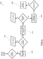
- FIG. 3 is a block chart that shows the hardware and software components of a charging station 100 in an embodiment.
- the charging station 100 comprises one or more power units 102 and a gateway node 104 which allows control and communication with the outside world.
- Each power unit 102 comprises a power card for charging a battery.
- the gateway node 104 is made with an embedded microprocessor system on which the main software applications, which allow the delivery of configuration and control services are run.
- the gateway node 104 thus implements the control unit of the charging station.
- the gateway node 104 allows the connection of the charging station to an existing telecommunications network.
- gateway node 104 For example, the following communication technologies are supported on the gateway node 104:
- the power units 102 are controlled by the gateway node 104.
- the communication with the power units 102 is performed by means of ModBusc commands which allows sending execution requests.
- the applications on the gateway can interact with the power units 102 by means of a layer between the application layer and the operating system consisting of a command server (ModBus command server).
- the application accepts local TCP/IP requests and sends them to the power units while maintaining consistency and atomicity of ModBus transactions.
- the application-level software is mainly divided into two parts: user management software and control software.
- the management software (application software) has the task of interacting with user applications during the delivery of the service.
- This software allows the identification of the user connected via app on the BLE interface of the gateway node.
- the software application authorizes the delivery and controls the eligibility to use the service.
- the control software (software supervisor) has the task of controlling the entire system during the operation and of reporting any critical issues.
- each cable is equipped with a specific authentication integrated circuit 36 for its unique identification during service.
- the authentication circuit has a read-only memory area that contains a unique cable identifier code (ROMID) which identifies each authentication circuit 36 and is inserted by the cable manufacturer.
- ROMID unique cable identifier code
- this memory area is made using DeepCover® technology and prevents the tampering of the information contained within the chip.
- the cable is therefore recorded in the manufacturing environment.
- CID unique cable identification token
- the unique token is implemented by a QR-Code, e.g. applied on the package of the cable purchased by the user.
- QR-Code e.g. applied on the package of the cable purchased by the user.
- the user can access the online cable activation services.
- the cable authentication circuit 36 in addition to the passive identification function, also performs an active hardware authentication function with the charging station 10; 100 through an authentication algorithm.
- the authentication algorithm is implemented with a symmetric (or pre-shared) key challenge-response authentication mechanism, SCRAM.
- each charging station is also equipped, e.g. within each power unit 102, with its own authentication circuit (e.g. the receiver integrated circuit 40 described above).
- the authentication mechanism provides the generation of a MAC using the SHA256 hash function.
- both parties In order to be authenticated, both parties must share the same encryption key used when composing the input for the function.
- the pre-shared key is the secret key used to ensure the non-repudiation of the parties. This key must be programmed in the memory area of both the authentication circuits in the cables and the charging station.
- Authentication is symmetric and occurs in both directions.
- the charging station generates a 32-bit long random challenge by means of a true random number generator (TRNG) inserted inside the charging station and then sends the challenge to the cable.
- TRNG true random number generator
- the authentication integrated circuit inside the cable calculates the digest of the challenge and of the pre-shared key programmed inside and returns the result to the authentication circuit of the charging station.
- the authentication circuit of the charging station calculates the digest of the same challenge using the internally programmed pre-shared key. If the received digest and the generated digest are the same, then the cable is authenticated by the charging station; vice versa if the authentication fails.
- the programming of the cables provides the writing of the pre-shared key in both authentication circuits.
- the charging cables are provided with hardware specialized to ensure their unique identification. Each cable is unique and can be combined with the user of the service.
- the unique identification of the cable ensures the non-clonability of the cables and the non-reproducibility of the cables.
- the unique identification of the cable allows limiting, if not preventing, the copying (cloning) of a cable, with the result of having two identical cables with the same ROMID, and the possibility for a competitor to make and offer cables compatible with the described system. This reduces the risk of spreading of counterfeit cables which could be dangerous if they do not comply with safety regulations and cause damage to both the charging station and the battery.
- the coding of the cables in order to identify them individually also allows the autonomous collection of information during their use; indeed, when a cable is connected to a charging station, the internal hardware of the station can check the authenticity of the cable in order to identify it.
- Figure 4 is a block chart of the authentication algorithm 200 of a cable.
- a first step of identifying when the cable is inserted into the connector of the charging station, the identifier code inside the cable (ROMID) is read by the charging station (step 210); if the cable can be read, the algorithm continues with the step of authenticating; otherwise, an error signal is generated (step 212).
- ROMID identifier code inside the cable
- the authenticity of the cable is checked during the second step of authenticating the inserted cable, (step 214), using an authentication algorithm, e.g. the symmetric key algorithm described above.
- an authentication algorithm e.g. the symmetric key algorithm described above.
- the charging station software proceeds by delivering the charge (step 216), possibly after waiting for authorization (step 218), e.g. from a service payment system.
- an additional mechanism for identifying the user of the delivery service e.g. by means of an application that can be installed on smartphones.
- the method comprises the following steps:
- the registration of the user allows the collection of the user's personal and identification data, e.g. by email address and the generation of a password to access services that allow the unique identification of the user.
- Other personal data of the user concerning other aspects of the service may be collected during this step.
- each user is assigned a unique user identifier code (UID), which allows each user to be identified.
- UID user identifier code
- This step allows establishing a two-way relationship between the unique token (CTID) and the unique user identifier code (UID).
- a user may own and activate more than one cable; in this case, there will be a list of cables activated and owned by a single user.
- the charging service is delivered after the user has been identified.
- Figure 5 shows an outline of the actions required to identify the user.
- the interaction of the charging station with the application installed on the smartphone takes place via a communication protocol based on Bluetooth® technology.
- the application sends the tuple (UID, ⁇ CTID1, CTID2, CTID3, ... ⁇ ) consisting of the unique identifier of the concerned user (UID) and the list of cables activated by the user ⁇ CTID1, CTID2, CTID3, ... ⁇ to the charging station.
- the charging station is therefore informed of potential cables which can be connected to the connector of a power unit. This information may be limited in time.
- the step of identifying the cable described above allows identifying the inserted cable uniquely and to retrieve the unique token (CTID) associated with the identifier code contained in the cable itself.
- CID unique token
- this step of identifying of the user is performed by the charging station either before or after the authentication algorithm is run. For example, if the outcome of the cable authentication algorithm is positive, the algorithm waits for the user identification procedure to be successfully completed during the step of waiting for authorization 218.
- This function can be useful in case of theft or loss of the cable.
- the user By connecting to the cable manufacturer's front-end services and logging in, the user can decide to report the lost or stolen cable so as to block it.
- a blocked cable cannot actually be used any longer for delivering the service.
Landscapes
- Engineering & Computer Science (AREA)
- Power Engineering (AREA)
- Transportation (AREA)
- Mechanical Engineering (AREA)
- Charge And Discharge Circuits For Batteries Or The Like (AREA)
- Electric Propulsion And Braking For Vehicles (AREA)
Abstract
Description
- The present invention relates to a charging system and method of the battery of electric vehicles, in particular of electric bicycles or pedal-assisted vehicles.
- The increasing diffusion of electric vehicles, in particular of bicycles, is also leading to the local installation of charging stations adapted to charge the battery of electric vehicles.
- In order to be able to charge, it is necessary to have a charging cable with an electrical connector that connects to a corresponding electrical connector on the charging station and, at the opposite end, an electrical connector that connects to the battery of the electric vehicle.
- One of the problems which afflict such charging systems based on locally installed charging stations is the compatibility with different types and brands of batteries.
- For example, batteries may differ from one another for a different supply voltage, typically 36 V or 48 V.
- Patent application
EP 2583859 A2 aims to solve the problem of different supply voltages by providing the charging cables with an electronic identification device, e.g. an RFID tag, a barcode or a QR-code, which contains information about the supply voltage, and the charging station with an electronic reading device capable of receiving the information contained in the electronic identification device and of communicating which supply voltage is to be used to a control unit of the charging station. - An examination of the different batteries on the market has also shown that there are two types of batteries which differ by a different charging method; the first, simpler type of battery allows the battery to be charged as soon as current is supplied to the terminals of the charging cable; the second type of battery, on the other hand, requires the battery to receive a control signal to connect the battery poles to the charging cable.
- This difference in the charging mode is also reflected in a multiplication of the circuits and of the charging cables.
- Another problem of the charging systems currently used is that while the charging station is designed to comply with electrical standards and the strictest safety regulations, it is not possible to be sure that the charging cable used by the user is also compatible with such standards and safety regulations.
- A non-conforming cable may not only be dangerous but may also cause damage to both the charging station and the battery to be charged.
- It is an object of the present invention to solve, at least in part and in a simple and cost-effect manner, the aforesaid drawbacks connected to the different charging modes.
- It is another object of the present invention to provide a charging system and method which allow ensuring that the charging service is delivered in a safe and efficient manner which respects the integrity of the charging station and of the vehicle battery.
- Such objects are achieved by a charging system according to claim 1 and by a charging method according to claim 13. The dependent claims describe preferred embodiments of the invention.
- According to an aspect of the invention, the charging system of a battery of an electric vehicle, in particular a bicycle, comprises a charging station and at least one charging cable connectable to a battery to be charged. The charging station comprises at least one power unit provided with a power card adapted to charge the battery and with a female-type connector adapted to connect to a male-type connector of the charging cable.
- The charging cable and the charging station are provided with respective authentication circuits configured to implement a cable authentication algorithm which, in case of positive outcome, enables charging the battery.
- In an embodiment, a unique cable identifier code is stored in the cable authentication circuit; the authentication circuit of the charging station is configured to read this unique cable identifier code.
- The charging method which uses the aforesaid charging system provides checking whether the cable is authentic by means of an authentication procedure run by the cable authentication circuits on the cable and on the charging station when the cable is connected to the charging station.
- In particular, the battery charging is subject to checking whether a user is enabled to use the charging service. Such a check is performed by means of a user identification procedure which comprises the steps of:
- associating a unique cable identifier code (ROMID) with each cable, during the step of manufacturing of the cable, said unique cable identifier code cannot be modified and can be read by the charging station when the cable is connected to the charging station;
- associating said unique cable identifier code with a unique cable identification token (CTID) and a unique user identifier code (UID);
- transmitting, by the user, said unique cable identification token (CTID) and said unique user identifier code (UID) to the charging station;
- connecting the cable to the charging station;
- obtaining the unique cable identification token (CTID) from the charging station by reading the unique cable identifier code (ROMID) stored in the connected cable;
- comparing, by the charging station, the obtained unique cable identification token (CTID) with the unique identifier code transmitted by the cable with the unique cable identification token (CTID) transmitted by the user.
- If the two tokens coincide, it means that the user is enabled to request the service and therefore the power supply to the battery is activated, or the cable authentication procedure is activated which, if the outcome is positive, enables the delivery of the service.
- If the two tokens do not coincide, an alarm signal is generated and delivery is not enabled.
- In an embodiment, the unique cable identification token (CTID) and the unique user identifier code (UID) are transmitted in a wireless manner by the user to the charging station via an app residing on a portable electronic device of the user, e.g. a smartphone.
- The features and advantages of the charging method and system according to the invention will be apparent from the following description which illustrates preferred embodiments, given by way of indicative, nonlimiting examples, with reference to the accompanying figures, in which:
-
figure 1 shows a charging system according to the invention; -
figure 2 is a wiring diagram of the charging system; -
figure 3 is a block chart of the hardware and software components of a charging station; -
figure 4 is a flow chart of an authentication algorithm of a charging cable; and -
figure 5 is a flow chart of a user identification algorithm. - In said drawings, a charging system of batteries of electric vehicles according to the invention is indicated with reference numeral 1 as a whole.
- The charging system 1 comprises a
charging station 10 and at least onecharging cable 12, which is connnectable to abattery 2 to be charged, e.g. the battery or accumulator of an electric or pedal-assisted bicycle. - The charging station 1 may be a public station installed near roads, parking lots, public buildings, etc.
- The
charging cable 12 connects thecharging station 10 to the battery to be charged. - The
charging system 10 comprises apower supply unit 14 adapted to generate at least one battery supply voltage. The battery supply voltage generated by thepower supply unit 14 is thus adapted to charge thebattery 2 at the working voltage expected for thebattery 2. - The
charging system 10 further comprises aservice power unit 16 adapted to generate at service voltage. Such a service voltage is not used to supply the battery but to supply further electronic devices of thecharging station 10, as described below. Theservice power unit 16 may be separated from thepower supply unit 14 or can be made inside thepower supply unit 14. - The
charging station 10 is managed by acontrol unit 18 which is operatively connected to thepower supply unit 14 and theservice supply unit 16. For example, thecontrol unit 18 is supplied by the operating voltage. - The
charging station 10 further comprises aregulator 20 connected to thecontrol unit 18 and adapted to supply a regulated charging current to thebattery 2 to be recharged. - For connecting to the
charging cable 12, thecharging station 10 is provided with at least one female-typemultipole charging connector 22, i.e. an electric socket. - This
multipole charging connector 22 comprises: - a negative terminal A and a positive terminal B, both connected to the
regulator 20; - a logic input C operatively connected to the
control unit 18; - a digital logic output D operatively connected to the
control unit 18. - The
charging cable 12 comprises a first male-typemultipole cable connector 24 adapted to be connected to themultipole charging connector 22, and, at the opposite end of the cable, a secondmultipole cable connector 26 connectable to thebattery 2. - The
second cable connector 26 is configured to connect to the connector on thebattery 2 to be charged. - The first
multipole cable connector 24 comprises: - a negative terminal A' and a positive terminal B' connectable to the negative and positive poles of the battery 2 (by means of the second multipole cable connector 26) and to the negative A and positive B terminals of the multipole charging connector 22 (by means of the first multipole cable connector 24);
- a connected connector check terminal C', connected to the negative terminal A' of the first
multipole cable connector 24 and connectable to the logic input C of themultipole charging connector 22; - a battery enabling terminal D' adapted to be connected to the digital logic output D of the
multipole charging connector 22. - The second
multipole cable connector 26 has a number of poles which depends on the type ofbattery 2 to be charged. In particular, for batteries of the first type, i.e. which allow charging as soon as current is supplied to the terminals of the charging cable, the secondmultipole cable connector 26 can have only two poles (positive and negative pole); for the second type of battery, i.e. which requires to be queried by a control signal to connect the battery poles to the charging cable, in addition to the positive and negative poles there will be a third pole for the control signal (as in the example shown infigure 2 ). - Turning back to the
control unit 18, it is provided with a connectedconnector check circuit 28, operatively connected to the logic input C of themultipole charging connector 22 and adapted to detect whether the logic input C is at the voltage present on the negative pole of thebattery 2. In the affirmative case, it means thatcharging cable 12 is correctly connected both to thebattery 2 to be charged and to thecharging connector 22. - The
control unit 18 is also provided with abattery enabling circuit 30 adapted to provide an enabling signal to the digital logic output D adapted to allow the connection of one of the battery poles, e.g. the positive pole, to the corresponding terminal of the charging cable, e.g. the positive terminal B'. - In an embodiment, the
control unit 18 has a further voltage presence input I connected to the positive terminal B of themultipole charging connector 22. Usually, this voltage presence input is at a zero logic value; if a battery of the second type is connected, in reply to the reception of the enabling signal D, thebattery 2 enables the transmission of its own voltage level on the positive pole B' of the malemultipole cable connector 24, and thus on the voltage presence input I. In the case of a battery of the first type, on the other hand, the internal protections with which it is provided do not allow the charging cable to read the voltage at the ends of the battery and the voltage presence input I remains at zero logic value. - In an embodiment, the charging
system 10 comprises aswitch device 44, e.g. a relay, between theregulator 20 and the chargingconnector 22, which switch device is controlled by thecontrol unit 18 to switch between an open position, in which it inhibits the passage of the charging electric current from theregulator 20 to the chargingconnector 22, and an open position, in which it allows the passage of the charging electric current from theregulator 20 to the chargingconnector 22. - In this embodiment, the voltage presence input I, if provided, is connected to the positive terminal B, downstream of the
switch device 44. - The
control unit 18 is programmed so as to implement the following battery charging procedure. - The correct connection of the battery charging cable is first checked by detecting, by means of the connected
connector test circuit 28, whether the logic input C is at the voltage present on thenegative battery pole 2. - In the affirmative case, the
control unit 18 commands thebattery enabling circuit 30 to supply the enabling signal to the digital logic output D. - The
control unit 18 thus remains in a state of waiting for enabling for a predetermined time, after which thecontrol unit 18 controls the delivery of charging current. - The predetermined time interval is chosen so that the batteries of the second type can receive and recognize the enabling signal and reply by connecting the battery poles to the charging cable. The predetermined time interval is preferably chosen on the basis of the longest response time among commercially available batteries of the second type.
- In accordance with an embodiment, either before or during the state of waiting for enabling, the
control unit 18 performs a step of self-diagnosing, in which it runs internal tests on the charging station to check that the electrical charging parameters correspond to the expected values, so as to prevent any malfunctioning of the charging station from affecting the connected battery. - For example, the control unit detects the value of the voltage output to the
regulator 20 by means of a regulated voltage input H. - During this step of self-diagnosing, the
switch device 44, if present, is left in the open position to protect the connected battery and is closed by thecontrol unit 18 only if no malfunctions are detected during the step of self-diagnosing. - In an embodiment, at the end of the step of waiting for enabling, the
control unit 18 checks whether a voltage corresponding to the positive pole of the battery is present on the voltage presence input I. In the affirmative case, it means that the connectedbattery 2 is of the second type. - Therefore, once the connected
connector check circuit 28 has detected a correct connection and the predetermined time interval of the step of waiting for enabling has elapsed, thecontrol unit 18 can establish which of the two types of battery is connected, between the first type with direct access and the second type with access conditioned by the battery enabling signal. - In an embodiment, the
control unit 18 is programmed to charge thebattery 2 with two different charging algorithms according to the connected battery type. - In an embodiment, the
power supply unit 14 is adapted to generate at least two different battery supply voltages, e.g. a first voltage adapted to charge a 36 V battery and a second voltage adapted to charge a 48 V battery. - The charging system 1, in this case, comprises at least two charging
cables 12, a first cable for charging a battery with a first working voltage and a second cable for charging a battery with a second working voltage. - Advantageously, the two charging
cables 12 are the same in terms of the number and the function of the terminals. - In particular, the
multipole charging connector 22 and the firstmultipole cable connector 24 has an additional voltage identification terminal F, F', respectively. The voltage identification terminal of the multipole charging connector F is connected to thecontrol unit 18. - The two cables can be identified in that only the voltage identification terminal F' is connected to either the positive terminal B' or the negative terminal A' in one of the two charging
cables 12. In this manner, thecontrol unit 18 can detect a different voltage on the voltage identification terminal F according to whether said voltage identification terminal F is either connected to or disconnected from the positive or negative terminal ofcable connector 24. Having identified the cable type and, consequently, the working voltage of the connected battery, the control unit supplies the corresponding battery supply voltage to theregulator 20. - For example, the
control unit 18 is normally configured to deliver the lowest among the supply voltages. Indeed, most batteries currently operate at 36 V. When thecontrol unit 18 detects the presence of a chargingcable 12 for a battery with a higher working voltage, e.g. 48 V, thecontrol unit 18 activates a voltage multiplying circuit to provide the appropriate voltage to theregulator 20. - In an embodiment, the first
multipole cable connector 24 is provided with an authentication integrated circuit comprising amemory 36 containing information about the source of the chargingcable 12 and connected to an additional communication terminal E' of themultipole cable connector 24. - The
multipole charging connector 22 has a corresponding communication terminal E connected to controlunit 18. The latter is provided with a receiver integratedcircuit 40 adapted to receive data from the authentication integrated circuit by means of communication terminals E, E'. - For example, the
receiver circuit 40 can send a query signal to the authentication integrated circuit. - Therefore, the authentication integrated circuit and the receiver integrated circuit form a pair of circuits capable of exchanging data for the main purpose of authenticating the charging cable.
- For example, if the
control unit 18 does not receive predetermined authentication information from the cable, it will not enable the delivery of the power voltage so as not to risk damaging the battery. -
Figure 3 is a block chart that shows the hardware and software components of a chargingstation 100 in an embodiment. - The charging
station 100 comprises one ormore power units 102 and agateway node 104 which allows control and communication with the outside world. - Each
power unit 102 comprises a power card for charging a battery. For example, there are fourpower units 102 in the chargingstation 100, e.g. interconnected in daisy-chains on an RS485 serial line and connected to thegateway node 104. - In an embodiment, the
gateway node 104 is made with an embedded microprocessor system on which the main software applications, which allow the delivery of configuration and control services are run. Thegateway node 104 thus implements the control unit of the charging station. - The
gateway node 104 allows the connection of the charging station to an existing telecommunications network. - For example, the following communication technologies are supported on the gateway node 104:
- IEEE 802.11 (Wi-Fi) in Station mode
- IEEE 802.11 (Wi-Fi) in Access Point (AP) mode
- IEEE 802.15.4 (Bluetooth)
- IEEE 802.3 (Ethernet)
- All the connectivity methods listed above are independent and can operate simultaneously on separate networks.
- In an embodiment, the
power units 102 are controlled by thegateway node 104. For example, the communication with thepower units 102 is performed by means of ModBusⓒ commands which allows sending execution requests. The applications on the gateway can interact with thepower units 102 by means of a layer between the application layer and the operating system consisting of a command server (ModBus command server). The application accepts local TCP/IP requests and sends them to the power units while maintaining consistency and atomicity of ModBus transactions. - In an embodiment, the application-level software is mainly divided into two parts: user management software and control software.
- As in greater detail described below, the management software (application software) has the task of interacting with user applications during the delivery of the service. This software allows the identification of the user connected via app on the BLE interface of the gateway node. Furthermore, the software application authorizes the delivery and controls the eligibility to use the service.
- The control software (software supervisor) has the task of controlling the entire system during the operation and of reporting any critical issues.
- Examples of charging cable authentication by the charging
station 10;100 will now be described. - At the end of the physical assembly operations of the cable, each cable is equipped with a specific authentication integrated
circuit 36 for its unique identification during service. - The authentication circuit has a read-only memory area that contains a unique cable identifier code (ROMID) which identifies each
authentication circuit 36 and is inserted by the cable manufacturer. - For example, this memory area is made using DeepCover® technology and prevents the tampering of the information contained within the chip.
- The cable is therefore recorded in the manufacturing environment.
- Furthermore, a unique cable identification token (CTID) is associated with each identifier code generated by the manufacturing system and used as a cable identifier during the steps of activating the charging cable, as will be described below.
- In an embodiment, the unique token is implemented by a QR-Code, e.g. applied on the package of the cable purchased by the user. With this QR-Code, the user can access the online cable activation services.
- The
cable authentication circuit 36, in addition to the passive identification function, also performs an active hardware authentication function with the chargingstation 10; 100 through an authentication algorithm. - In an embodiment, the authentication algorithm is implemented with a symmetric (or pre-shared) key challenge-response authentication mechanism, SCRAM.
- This mutual authentication mechanism allows the charging station to determine the authenticity of the connected cable on the hardware level. In order to authenticate the cable, each charging station is also equipped, e.g. within each
power unit 102, with its own authentication circuit (e.g. the receiver integratedcircuit 40 described above). - The authentication mechanism provides the generation of a MAC using the SHA256 hash function. In order to be authenticated, both parties must share the same encryption key used when composing the input for the function. The pre-shared key is the secret key used to ensure the non-repudiation of the parties. This key must be programmed in the memory area of both the authentication circuits in the cables and the charging station.
- Authentication is symmetric and occurs in both directions. The charging station generates a 32-bit long random challenge by means of a true random number generator (TRNG) inserted inside the charging station and then sends the challenge to the cable. The authentication integrated circuit inside the cable calculates the digest of the challenge and of the pre-shared key programmed inside and returns the result to the authentication circuit of the charging station. At the same time, the authentication circuit of the charging station calculates the digest of the same challenge using the internally programmed pre-shared key. If the received digest and the generated digest are the same, then the cable is authenticated by the charging station; vice versa if the authentication fails.
- The programming of the cables provides the writing of the pre-shared key in both authentication circuits.
- The procedure for identifying the charging cables will now be described.
- As mentioned above, the charging cables are provided with hardware specialized to ensure their unique identification. Each cable is unique and can be combined with the user of the service.
- The unique identification of the cable ensures the non-clonability of the cables and the non-reproducibility of the cables. In other words, the unique identification of the cable allows limiting, if not preventing, the copying (cloning) of a cable, with the result of having two identical cables with the same ROMID, and the possibility for a competitor to make and offer cables compatible with the described system. This reduces the risk of spreading of counterfeit cables which could be dangerous if they do not comply with safety regulations and cause damage to both the charging station and the battery.
- Furthermore, the coding of the cables in order to identify them individually also allows the autonomous collection of information during their use; indeed, when a cable is connected to a charging station, the internal hardware of the station can check the authenticity of the cable in order to identify it.
-
Figure 4 is a block chart of theauthentication algorithm 200 of a cable. - Such an algorithm occurs in two steps: authentication and identification.
- In a first step of identifying, when the cable is inserted into the connector of the charging station, the identifier code inside the cable (ROMID) is read by the charging station (step 210); if the cable can be read, the algorithm continues with the step of authenticating; otherwise, an error signal is generated (step 212).
- The authenticity of the cable is checked during the second step of authenticating the inserted cable, (step 214), using an authentication algorithm, e.g. the symmetric key algorithm described above.
- If the cable is genuine, then the charging station software proceeds by delivering the charge (step 216), possibly after waiting for authorization (step 218), e.g. from a service payment system.
- A user identification process will now be described.
- In some embodiments, in addition to the authentication mechanism of the cable, there may be an additional mechanism for identifying the user of the delivery service, e.g. by means of an application that can be installed on smartphones.
- The method comprises the following steps:
- 1. Buying a cable from the cable manufacturer
- 2. Registering the user on the cable manufacturer's website
- 3. Activating the purchased cable
- 4. Installing the application.
- The registration of the user allows the collection of the user's personal and identification data, e.g. by email address and the generation of a password to access services that allow the unique identification of the user. Other personal data of the user concerning other aspects of the service may be collected during this step.
- Once registered, each user is assigned a unique user identifier code (UID), which allows each user to be identified. Indeed, the activation of the cable requires the user to be logged into the online service of the cable manufacturer and the activation can be made only by the user in possession of the QR-Code associated with the package of the cable purchased or printed on the cable itself.
- This step allows establishing a two-way relationship between the unique token (CTID) and the unique user identifier code (UID).
- It is worth noting that a user may own and activate more than one cable; in this case, there will be a list of cables activated and owned by a single user.
- In an embodiment, the charging service is delivered after the user has been identified.
Figure 5 shows an outline of the actions required to identify the user. - The functional requirement of the user login of the installed application and the synchronization between the application and the back-end services of the cable manufacturer are highlighted in particular. This step is necessary to keep a local copy of the user's activated cable list synchronized. The copy is made in one direction only using the information contained in the cable manufacturer's back-end as the master and the temporary copy kept on the application installed on the smartphone as the slave.
- Any changes to a user's active cable list must, therefore, be made by means of the cable manufacturer's front-end services and regular synchronization of this information by the application installed on the smartphone is necessary for this to take effect.
- It is worth noting that in this manner there are no particular constraints on the number of installed applications and therefore it is assumed that a user will not install the application and log in on devices which are not directly in their possession.
- In an embodiment, the interaction of the charging station with the application installed on the smartphone takes place via a communication protocol based on Bluetooth® technology. The application sends the tuple (UID, {CTID1, CTID2, CTID3, ...}) consisting of the unique identifier of the concerned user (UID) and the list of cables activated by the user {CTID1, CTID2, CTID3, ...} to the charging station.
- It is worth noting that this mechanism takes place in a competitive manner by not imposing limits on the number of users requesting the delivery. In this case, there will be multiple tuples containing lists of cables for different users (UID1, {CTID1, CTID2, CTID3, ...}) (UID2, {CTID4, CTID5, CTID6, ...}) (UID3, {CTID7, CTID8, CTID9, ...}), etc.
- The charging station is therefore informed of potential cables which can be connected to the connector of a power unit. This information may be limited in time.
- When the cable is actually connected to a charging station, the step of identifying the cable described above allows identifying the inserted cable uniquely and to retrieve the unique token (CTID) associated with the identifier code contained in the cable itself.
- By comparing the unique token of the connected cable with the tokens contained in the lists of expected cables {CTID1, CTID2, CTID3, ...}, {CTID4, CTID5, CTID6, ...}, {CTID7, CTID8, CTID9, ...}, it is thus possible to uniquely identify the user (UID) requesting the delivery, thus proceeding with the supplying of the service.
- In an embodiment, with reference to the cable authentication procedure described above and illustrated in the block chart in
figure 4 , this step of identifying of the user is performed by the charging station either before or after the authentication algorithm is run. For example, if the outcome of the cable authentication algorithm is positive, the algorithm waits for the user identification procedure to be successfully completed during the step of waiting forauthorization 218. - It is worth noting that since the cable is paired with only one user, it is possible to decide to lock the cable to prevent its use.
- This function can be useful in case of theft or loss of the cable. By connecting to the cable manufacturer's front-end services and logging in, the user can decide to report the lost or stolen cable so as to block it.
- A blocked cable cannot actually be used any longer for delivering the service.
- A person skilled in the art may make changes and adaptations to the embodiments of the charging system of the invention or can replace elements with others which are functionally equivalent to satisfy contingent needs without departing from the scope of protection of the appended claims. All the features described above as belonging to one possible embodiment may be implemented independently from the other embodiments described.
Claims (15)
- A charging system of a battery of an electric vehicle, in particular a bicycle, comprising a charging station (10) and at least one charging cable (12) connectable to a battery (2) to be charged, wherein the charging station (10) comprises:- a power supply unit (14) adapted to generate at least one battery supply voltage;- a service power supply unit (16) adapted to generate a service voltage;- a control unit (18) connected to the power supply unit and to the service power supply unit, the control unit being supplied by the service voltage;- a regulator (20) connected to the control unit and adapted to supply a regulated charging current to the battery to be recharged;- a female-type multipole charging connector (22) comprising:- a positive terminal (B) and a negative terminal (A), connected to the regulator (20);- a logic input (C) operatively connected to the control unit;- a digital logic output (D) operatively connected to the control unit;and wherein the charging cable comprises a first male-type multipole cable connector (24) adapted to be connected to the female-type multipole charging connector (22), and, at the opposite end of the cable, a second multipole cable connector (26) connectable to the battery, said first multipole cable connector (24) comprising:- a positive terminal (B') and a negative terminal (A') connectable to the battery positive and negative poles of the second multipole cable connector (26) and to the positive (B) and negative (A) terminals of the multipole charging connector (22);- a connected connector check terminal (C'), connected to the negative terminal (A') and connectable to the logic input (C) of the multipole charging connector;- a battery enabling terminal (D') adapted to be connected to the digital logic output (D) of the multipole charging connector (22),the control unit (18) being provided with:- a connected connector check circuit (28), operatively connected to the logic input (C) of the multipole charging connector (22) and adapted to detect whether the logic input (C) is at the voltage present on the negative battery pole;- a battery enabling circuit (30) adapted to supply an enabling signal to the digital logic output (D) adapted to allow the connection of the positive battery pole to the positive terminal (B') of the charging cable; the control unit (18) being programmed to implement a charging process which comprises the steps of:- detecting, by means of the connected connector check circuit (28), whether the logic input (C) is at the voltage present on the negative battery pole (2);- in the affirmative case, commanding the battery enabling circuit (30) to supply the enabling signal to the digital logic output (D);- remaining in a waiting for enabling state for a predetermined time interval, calculated on the basis of the response time of the battery to the enabling signal;- at the end of said predetermined time interval, commanding the delivery of the charging current.
- A charging system according to claim 1, wherein the control unit (18) is provided with a further voltage presence input (I) connected to the positive terminal (B) of the multipole charging connector (22) and is programmed to check, at the end of the step of waiting for enabling, whether voltage corresponding to the voltage present on the positive battery pole is present on said voltage presence input (I).
- A charging system according to claim 2, wherein the control unit is programmed to charge the battery with two different charging algorithms according to the voltage value present on the voltage presence input (I).
- A charging system according to any one of the preceding claims, wherein:- the power supply unit (14) is adapted to generate at least two different battery supply voltages,- the system comprises at least two identical charging cables (12),- the multipole charging connector (22) and the first multipole cable connector (24) having an additional voltage identification terminal (F, F'), the voltage identification terminal (F) of the multipole charging connector (22) being connected to the control unit (18),- in one of the two charging cables the voltage identification terminal (F') being connected to one of the two positive or negative terminals (A', B') so that the control unit can detect a different voltage on the voltage identification terminal (F) according to whether said voltage identification terminal is connected to or disconnected from the positive or negative terminal of the cable connector and supplies a respective battery supply voltage to the regulator.
- A charging system according to any one of the preceding claims, wherein the first multipole cable connector (24) is provided with an authentication integrated circuit comprising a memory unit (36) containing information on the source of the cable and connected to a further communication terminal (E') of the multipole cable connector, the multipole charging connector being provided with a corresponding communication terminal (E) connected to the control unit, the control unit being provided with a receiver integrated circuit (40) adapted to receive data from the authentication integrated circuit.
- A charging system according to any one of the preceding claims, wherein the charging station (10) comprises a switch device (44), e.g. a relay, between the regulator (20) and the charging connector (22), which switch device is controlled by the control unit (18) to switch between an open position, in which it inhibits the passage of the charging electrical current from the regulator (20) to the charging connector (22), and an open position, in which it allows the passage of the charging electrical current from the regulator (20) to the charging connector (22).
- A charging system according to any one of the preceding claims, wherein the charging cable and the charging station are provided with respective authentication circuits configured to implement a cable authentication algorithm which, in case of a positive outcome, enables charging the battery.
- A charging system of a battery of an electric vehicle, in particular a bicycle, comprising a charging station (10; 100) and at least one charging cable (12) connectable to a battery (2) to be charged, wherein the charging station (10; 100) comprises at least one power unit (102) provided with a power card adapted to charge the battery and a female-type connector (22) adapted to connect to a male-type connector (24) of the charging cable,
wherein the charging cable and the charging station are provided with respective authentication circuits configured to implement a cable authentication algorithm which, in case of a positive outcome, enables charging the battery. - A system according to claim 7 or 8, wherein the authentication algorithm is implemented with a symmetric key challenge-response authentication mechanism (SCRAM), the authentication circuit of the cable and the authentication circuit of the charging station sharing the same encryption key.
- A system according to any of claims 7-9, wherein a unique identifier code (ROMID), which cannot be changed, is stored in the cable authentication circuit, and wherein the authentication circuit of the charging station is configured to read said unique identifier code.
- A system according to the preceding claim, wherein the authentication algorithm is implemented with a symmetric key challenge-response authentication mechanism (SCRAM), the authentication circuit of the cable and the authentication circuit of the charging station sharing the same encryption key.
- A system according to any of claims 7-11, wherein a unique identifier code (ROMID), which cannot be changed, is stored in the cable authentication circuit, and wherein the authentication circuit of the charging station is configured to read said unique identifier code.
- A charging method of a battery of an electric vehicle, in particular a bicycle, comprising the steps of:- providing a charging system according to any one of claims from 7 to 12;- checking whether the cable is authentic by means of an authentication procedure performed by the cable authentication circuits on the cable and by the charging station when the cable is connected to the charging station.
- A method according to the preceding claim, wherein the battery charging is subject to checking whether a user is enabled to use the charging service, said check being carried out by means of a user identification procedure which comprises the steps of:- associating a unique cable identifier code (ROMID) with each cable, during the step of manufacturing of the cable, said unique cable identifier code being readable by the charging station when the cable is connected to the charging station;- associating said unique cable identifier code with a unique cable identification token (CTID) and a unique user identifier code (UID);- transmitting, by the user, said unique cable identification token (CTID) and said unique user identifier code (UID) to the charging station;- connecting the cable to the charging station;- obtaining the unique cable identification token (CTID) from the charging station by reading the unique cable identifier code (ROMID) stored in the connected cable;- comparing, by the charging station, the obtained unique cable identification token (CTID) with the unique identifier code transmitted by the cable with the unique cable identification token (CTID) transmitted by the user.
- A method according to the preceding claim, wherein the unique cable identification token (CTID) and the unique user identifier code (UID) are transmitted in a wireless manner by the user to the charging station via an app residing on a portable electronic device of the user.
Priority Applications (1)
| Application Number | Priority Date | Filing Date | Title |
|---|---|---|---|
| EP21153640.4A EP3831644B1 (en) | 2019-02-12 | 2020-02-10 | Charging system and method of a battery of an electric vehicle |
Applications Claiming Priority (2)
| Application Number | Priority Date | Filing Date | Title |
|---|---|---|---|
| IT102019000002003A IT201900002003A1 (en) | 2019-02-12 | 2019-02-12 | RECHARGE SYSTEM OF A BATTERY OF AN ELECTRIC VEHICLE |
| IT202000002455 | 2020-02-07 |
Related Child Applications (2)
| Application Number | Title | Priority Date | Filing Date |
|---|---|---|---|
| EP21153640.4A Division EP3831644B1 (en) | 2019-02-12 | 2020-02-10 | Charging system and method of a battery of an electric vehicle |
| EP21153640.4A Division-Into EP3831644B1 (en) | 2019-02-12 | 2020-02-10 | Charging system and method of a battery of an electric vehicle |
Publications (4)
| Publication Number | Publication Date |
|---|---|
| EP3696011A2 true EP3696011A2 (en) | 2020-08-19 |
| EP3696011A3 EP3696011A3 (en) | 2020-11-11 |
| EP3696011C0 EP3696011C0 (en) | 2023-08-30 |
| EP3696011B1 EP3696011B1 (en) | 2023-08-30 |
Family
ID=69411398
Family Applications (2)
| Application Number | Title | Priority Date | Filing Date |
|---|---|---|---|
| EP20156452.3A Active EP3696011B1 (en) | 2019-02-12 | 2020-02-10 | Charging system and method of a battery of an electric vehicle |
| EP21153640.4A Active EP3831644B1 (en) | 2019-02-12 | 2020-02-10 | Charging system and method of a battery of an electric vehicle |
Family Applications After (1)
| Application Number | Title | Priority Date | Filing Date |
|---|---|---|---|
| EP21153640.4A Active EP3831644B1 (en) | 2019-02-12 | 2020-02-10 | Charging system and method of a battery of an electric vehicle |
Country Status (1)
| Country | Link |
|---|---|
| EP (2) | EP3696011B1 (en) |
Cited By (2)
| Publication number | Priority date | Publication date | Assignee | Title |
|---|---|---|---|---|
| FR3109338A1 (en) * | 2020-04-17 | 2021-10-22 | Adeos | Cable and charging station for electric or electric bicycle |
| WO2022197192A1 (en) * | 2021-03-19 | 2022-09-22 | Hikotron Limited | Electric vehicle charging systems, methods and devices |
Citations (1)
| Publication number | Priority date | Publication date | Assignee | Title |
|---|---|---|---|---|
| EP2583859A2 (en) | 2011-10-20 | 2013-04-24 | Volkmar Schitter | Charging cable and charging system for electric vehicles |
Family Cites Families (11)
| Publication number | Priority date | Publication date | Assignee | Title |
|---|---|---|---|---|
| ITMI20061438A1 (en) * | 2006-07-24 | 2008-01-25 | Campagnolo Srl | METHOD AND RECHARGING SYSTEM OF A BATTERY POWER UNIT |
| JP4366385B2 (en) * | 2006-08-31 | 2009-11-18 | 株式会社東海理化電機製作所 | Charging system |
| DE102009030092A1 (en) * | 2009-06-22 | 2010-12-30 | Rwe Ag | Charging cable plug for electric vehicles |
| JP2012135111A (en) * | 2010-12-21 | 2012-07-12 | Denso Corp | Vehicle charge cable management system |
| WO2012111081A1 (en) * | 2011-02-15 | 2012-08-23 | トヨタ自動車株式会社 | Adaptor and vehicle provided with same, and vehicle control method |
| JP2013198279A (en) * | 2012-03-19 | 2013-09-30 | Fukuoka Univ | Charge cable and charge system |
| KR20140140203A (en) * | 2013-05-28 | 2014-12-09 | 엘에스산전 주식회사 | Multiple charging providing apparatus for supporting charging multiple charging target devices, charging station operating server, electric charging system, and operating method thereof |
| JP5831524B2 (en) * | 2013-10-23 | 2015-12-09 | 株式会社デンソー | Vehicle charging cable |
| KR101587357B1 (en) * | 2014-09-01 | 2016-01-20 | 엘에스산전 주식회사 | Recharging device and recharging method for vehicle |
| KR20160031809A (en) * | 2014-09-15 | 2016-03-23 | 엘에스산전 주식회사 | Electic automobile recharge apparatus |
| KR20190006211A (en) * | 2017-07-10 | 2019-01-18 | 주식회사 젭얼라이언스 | Automobile charging system using augmented reality and charging method therefor |
-
2020
- 2020-02-10 EP EP20156452.3A patent/EP3696011B1/en active Active
- 2020-02-10 EP EP21153640.4A patent/EP3831644B1/en active Active
Patent Citations (1)
| Publication number | Priority date | Publication date | Assignee | Title |
|---|---|---|---|---|
| EP2583859A2 (en) | 2011-10-20 | 2013-04-24 | Volkmar Schitter | Charging cable and charging system for electric vehicles |
Cited By (2)
| Publication number | Priority date | Publication date | Assignee | Title |
|---|---|---|---|---|
| FR3109338A1 (en) * | 2020-04-17 | 2021-10-22 | Adeos | Cable and charging station for electric or electric bicycle |
| WO2022197192A1 (en) * | 2021-03-19 | 2022-09-22 | Hikotron Limited | Electric vehicle charging systems, methods and devices |
Also Published As
| Publication number | Publication date |
|---|---|
| EP3831644B1 (en) | 2023-07-19 |
| EP3696011C0 (en) | 2023-08-30 |
| EP3831644C0 (en) | 2023-07-19 |
| EP3831644A2 (en) | 2021-06-09 |
| EP3831644A3 (en) | 2021-08-25 |
| EP3696011B1 (en) | 2023-08-30 |
| EP3696011A3 (en) | 2020-11-11 |
Similar Documents
| Publication | Publication Date | Title |
|---|---|---|
| US10682981B2 (en) | Systems and methods for networked device security | |
| CN101909927B (en) | Charging system for electric vehicle | |
| CN103227776B (en) | Configuration method, configuration device, computer program product and control system | |
| US9688155B2 (en) | Authentication and pairing of a mobile device to an external power source | |
| CN101855653B (en) | Lock administration system | |
| US20190299803A1 (en) | Vehicle, vehicle charging system and vehicle charging method | |
| CN109849726A (en) | For the charging system to electric vehicle charging and for authorizing the method from charging station to electric vehicle charging | |
| CN105207287B (en) | A kind of charging pile management system and method | |
| CN109272606A (en) | A kind of smart lock monitoring equipment, method and storage medium based on block chain | |
| US8978109B2 (en) | Electronic control device for a vehicle | |
| CN103988218A (en) | Authentication method | |
| EP3831644B1 (en) | Charging system and method of a battery of an electric vehicle | |
| JP2012141676A (en) | Control apparatus, control method, and control program | |
| CN102985299A (en) | Electric vehicle theft preventing device | |
| CN106682905B (en) | Application unlocking method | |
| CN103236921B (en) | Intelligent electric energy meter based on Internet of Things information security management module | |
| US11993165B2 (en) | Charging system and method of a battery of an electric vehicle based on cable authentication | |
| US11001160B2 (en) | Electrically operated vehicle having charging cable | |
| KR20230107775A (en) | System and method of certifying genuine product of battery for vehicle through user terminal | |
| KR102384371B1 (en) | Smart charging system and smart charging method including smart concentric plug, user terminal, and power management server | |
| US11699817B2 (en) | Apparatus and methods for removable battery module with internal relay and internal controller | |
| CN110065412A (en) | For running the method for being directed to the static charging station of vehicle, charging system | |
| CN109979116A (en) | A kind of offline cryptogram encryption method about equipment leasing | |
| US20180060558A1 (en) | Method of authenticating a user at a security device | |
| US10664930B2 (en) | Device for powering an electrical appliance |
Legal Events
| Date | Code | Title | Description |
|---|---|---|---|
| PUAI | Public reference made under article 153(3) epc to a published international application that has entered the european phase |
Free format text: ORIGINAL CODE: 0009012 |
|
| STAA | Information on the status of an ep patent application or granted ep patent |
Free format text: STATUS: THE APPLICATION HAS BEEN PUBLISHED |
|
| AK | Designated contracting states |
Kind code of ref document: A2 Designated state(s): AL AT BE BG CH CY CZ DE DK EE ES FI FR GB GR HR HU IE IS IT LI LT LU LV MC MK MT NL NO PL PT RO RS SE SI SK SM TR |
|
| AX | Request for extension of the european patent |
Extension state: BA ME |
|
| PUAL | Search report despatched |
Free format text: ORIGINAL CODE: 0009013 |
|
| AK | Designated contracting states |
Kind code of ref document: A3 Designated state(s): AL AT BE BG CH CY CZ DE DK EE ES FI FR GB GR HR HU IE IS IT LI LT LU LV MC MK MT NL NO PL PT RO RS SE SI SK SM TR |
|
| AX | Request for extension of the european patent |
Extension state: BA ME |
|
| RIC1 | Information provided on ipc code assigned before grant |
Ipc: B60L 53/18 20190101ALI20201002BHEP Ipc: B60L 53/16 20190101AFI20201002BHEP Ipc: B60L 50/20 20190101ALI20201002BHEP |
|
| 111L | Licence recorded |
Designated state(s): AL AT BE BG CH CY CZ DE DK EE ES FI FR GB GR HR HU IE IS IT LT LU LV MC MK MT NL NO PL PT RO RS SE SI SK SM TR Free format text: EXCLUSIVE LICENSE Name of requester: BIKEF SRL, IT Effective date: 20210205 |
|
| STAA | Information on the status of an ep patent application or granted ep patent |
Free format text: STATUS: REQUEST FOR EXAMINATION WAS MADE |
|
| 17P | Request for examination filed |
Effective date: 20210510 |
|
| RBV | Designated contracting states (corrected) |
Designated state(s): AL AT BE BG CH CY CZ DE DK EE ES FI FR GB GR HR HU IE IS IT LI LT LU LV MC MK MT NL NO PL PT RO RS SE SI SK SM TR |
|
| GRAP | Despatch of communication of intention to grant a patent |
Free format text: ORIGINAL CODE: EPIDOSNIGR1 |
|
| STAA | Information on the status of an ep patent application or granted ep patent |
Free format text: STATUS: GRANT OF PATENT IS INTENDED |
|
| INTG | Intention to grant announced |
Effective date: 20230117 |
|
| GRAS | Grant fee paid |
Free format text: ORIGINAL CODE: EPIDOSNIGR3 |
|
| GRAA | (expected) grant |
Free format text: ORIGINAL CODE: 0009210 |
|
| STAA | Information on the status of an ep patent application or granted ep patent |
Free format text: STATUS: THE PATENT HAS BEEN GRANTED |
|
| 111L | Licence recorded |
Designated state(s): AL AT BE BG CH CY CZ DE DK EE ES FI FR GB GR HR HU IE IS IT LT LU LV MC MK MT NL NO PL PT RO RS SE SI SK SM TR Free format text: EXCLUSIVE LICENSE Name of requester: BIKEF SRL, IT Effective date: 20210205 |
|
| AK | Designated contracting states |
Kind code of ref document: B1 Designated state(s): AL AT BE BG CH CY CZ DE DK EE ES FI FR GB GR HR HU IE IS IT LI LT LU LV MC MK MT NL NO PL PT RO RS SE SI SK SM TR |
|
| RAP3 | Party data changed (applicant data changed or rights of an application transferred) |
Owner name: FERRARI, MASSIMO |
|
| REG | Reference to a national code |
Ref country code: GB Ref legal event code: FG4D |
|
| RIN1 | Information on inventor provided before grant (corrected) |
Inventor name: FERRARI, MASSIMO |
|
| REG | Reference to a national code |
Ref country code: CH Ref legal event code: EP |
|
| REG | Reference to a national code |
Ref country code: DE Ref legal event code: R096 Ref document number: 602020016477 Country of ref document: DE |
|
| REG | Reference to a national code |
Ref country code: IE Ref legal event code: FG4D |
|
| U01 | Request for unitary effect filed |
Effective date: 20230929 |
|
| U07 | Unitary effect registered |
Designated state(s): AT BE BG DE DK EE FI FR IT LT LU LV MT NL PT SE SI Effective date: 20231006 |
|
| PG25 | Lapsed in a contracting state [announced via postgrant information from national office to epo] |
Ref country code: GR Free format text: LAPSE BECAUSE OF FAILURE TO SUBMIT A TRANSLATION OF THE DESCRIPTION OR TO PAY THE FEE WITHIN THE PRESCRIBED TIME-LIMIT Effective date: 20231201 |
|
| PG25 | Lapsed in a contracting state [announced via postgrant information from national office to epo] |
Ref country code: IS Free format text: LAPSE BECAUSE OF FAILURE TO SUBMIT A TRANSLATION OF THE DESCRIPTION OR TO PAY THE FEE WITHIN THE PRESCRIBED TIME-LIMIT Effective date: 20231230 |
|
| PG25 | Lapsed in a contracting state [announced via postgrant information from national office to epo] |
Ref country code: RS Free format text: LAPSE BECAUSE OF FAILURE TO SUBMIT A TRANSLATION OF THE DESCRIPTION OR TO PAY THE FEE WITHIN THE PRESCRIBED TIME-LIMIT Effective date: 20230830 Ref country code: NO Free format text: LAPSE BECAUSE OF FAILURE TO SUBMIT A TRANSLATION OF THE DESCRIPTION OR TO PAY THE FEE WITHIN THE PRESCRIBED TIME-LIMIT Effective date: 20231130 Ref country code: IS Free format text: LAPSE BECAUSE OF FAILURE TO SUBMIT A TRANSLATION OF THE DESCRIPTION OR TO PAY THE FEE WITHIN THE PRESCRIBED TIME-LIMIT Effective date: 20231230 Ref country code: HR Free format text: LAPSE BECAUSE OF FAILURE TO SUBMIT A TRANSLATION OF THE DESCRIPTION OR TO PAY THE FEE WITHIN THE PRESCRIBED TIME-LIMIT Effective date: 20230830 Ref country code: GR Free format text: LAPSE BECAUSE OF FAILURE TO SUBMIT A TRANSLATION OF THE DESCRIPTION OR TO PAY THE FEE WITHIN THE PRESCRIBED TIME-LIMIT Effective date: 20231201 |
|
| PG25 | Lapsed in a contracting state [announced via postgrant information from national office to epo] |
Ref country code: PL Free format text: LAPSE BECAUSE OF FAILURE TO SUBMIT A TRANSLATION OF THE DESCRIPTION OR TO PAY THE FEE WITHIN THE PRESCRIBED TIME-LIMIT Effective date: 20230830 |
|
| U20 | Renewal fee paid [unitary effect] |
Year of fee payment: 5 Effective date: 20240222 |
|
| PG25 | Lapsed in a contracting state [announced via postgrant information from national office to epo] |
Ref country code: ES Free format text: LAPSE BECAUSE OF FAILURE TO SUBMIT A TRANSLATION OF THE DESCRIPTION OR TO PAY THE FEE WITHIN THE PRESCRIBED TIME-LIMIT Effective date: 20230830 |
|
| PG25 | Lapsed in a contracting state [announced via postgrant information from national office to epo] |
Ref country code: SM Free format text: LAPSE BECAUSE OF FAILURE TO SUBMIT A TRANSLATION OF THE DESCRIPTION OR TO PAY THE FEE WITHIN THE PRESCRIBED TIME-LIMIT Effective date: 20230830 Ref country code: RO Free format text: LAPSE BECAUSE OF FAILURE TO SUBMIT A TRANSLATION OF THE DESCRIPTION OR TO PAY THE FEE WITHIN THE PRESCRIBED TIME-LIMIT Effective date: 20230830 Ref country code: ES Free format text: LAPSE BECAUSE OF FAILURE TO SUBMIT A TRANSLATION OF THE DESCRIPTION OR TO PAY THE FEE WITHIN THE PRESCRIBED TIME-LIMIT Effective date: 20230830 Ref country code: CZ Free format text: LAPSE BECAUSE OF FAILURE TO SUBMIT A TRANSLATION OF THE DESCRIPTION OR TO PAY THE FEE WITHIN THE PRESCRIBED TIME-LIMIT Effective date: 20230830 Ref country code: SK Free format text: LAPSE BECAUSE OF FAILURE TO SUBMIT A TRANSLATION OF THE DESCRIPTION OR TO PAY THE FEE WITHIN THE PRESCRIBED TIME-LIMIT Effective date: 20230830 |
|
| REG | Reference to a national code |
Ref country code: DE Ref legal event code: R097 Ref document number: 602020016477 Country of ref document: DE |
|
| PLBE | No opposition filed within time limit |
Free format text: ORIGINAL CODE: 0009261 |
|
| STAA | Information on the status of an ep patent application or granted ep patent |
Free format text: STATUS: NO OPPOSITION FILED WITHIN TIME LIMIT |
|
| 26N | No opposition filed |
Effective date: 20240603 |