EP3695978A1 - Printer - Google Patents
Printer Download PDFInfo
- Publication number
- EP3695978A1 EP3695978A1 EP19214417.8A EP19214417A EP3695978A1 EP 3695978 A1 EP3695978 A1 EP 3695978A1 EP 19214417 A EP19214417 A EP 19214417A EP 3695978 A1 EP3695978 A1 EP 3695978A1
- Authority
- EP
- European Patent Office
- Prior art keywords
- work platform
- opening
- medium
- printer
- state
- Prior art date
- Legal status (The legal status is an assumption and is not a legal conclusion. Google has not performed a legal analysis and makes no representation as to the accuracy of the status listed.)
- Withdrawn
Links
- 230000007246 mechanism Effects 0.000 claims abstract description 64
- 238000007639 printing Methods 0.000 claims abstract description 16
- 238000000034 method Methods 0.000 claims abstract description 5
- 230000008569 process Effects 0.000 claims abstract description 5
- 238000001514 detection method Methods 0.000 claims description 6
- 238000004804 winding Methods 0.000 claims 2
- 238000007689 inspection Methods 0.000 description 13
- 238000012423 maintenance Methods 0.000 description 7
- 239000000428 dust Substances 0.000 description 6
- 238000011144 upstream manufacturing Methods 0.000 description 6
- 230000008878 coupling Effects 0.000 description 3
- 238000010168 coupling process Methods 0.000 description 3
- 238000005859 coupling reaction Methods 0.000 description 3
- 230000008859 change Effects 0.000 description 1
- 239000003086 colorant Substances 0.000 description 1
- 230000008602 contraction Effects 0.000 description 1
- 238000010586 diagram Methods 0.000 description 1
- 238000001035 drying Methods 0.000 description 1
- 238000005516 engineering process Methods 0.000 description 1
- 239000004744 fabric Substances 0.000 description 1
- 238000009434 installation Methods 0.000 description 1
- 238000012986 modification Methods 0.000 description 1
- 230000004048 modification Effects 0.000 description 1
- 239000000126 substance Substances 0.000 description 1
- 238000011179 visual inspection Methods 0.000 description 1
- 239000002699 waste material Substances 0.000 description 1
Images









Classifications
-
- B—PERFORMING OPERATIONS; TRANSPORTING
- B41—PRINTING; LINING MACHINES; TYPEWRITERS; STAMPS
- B41J—TYPEWRITERS; SELECTIVE PRINTING MECHANISMS, i.e. MECHANISMS PRINTING OTHERWISE THAN FROM A FORME; CORRECTION OF TYPOGRAPHICAL ERRORS
- B41J11/00—Devices or arrangements of selective printing mechanisms, e.g. ink-jet printers or thermal printers, for supporting or handling copy material in sheet or web form
- B41J11/001—Handling wide copy materials
-
- B—PERFORMING OPERATIONS; TRANSPORTING
- B41—PRINTING; LINING MACHINES; TYPEWRITERS; STAMPS
- B41J—TYPEWRITERS; SELECTIVE PRINTING MECHANISMS, i.e. MECHANISMS PRINTING OTHERWISE THAN FROM A FORME; CORRECTION OF TYPOGRAPHICAL ERRORS
- B41J29/00—Details of, or accessories for, typewriters or selective printing mechanisms not otherwise provided for
- B41J29/02—Framework
-
- B—PERFORMING OPERATIONS; TRANSPORTING
- B41—PRINTING; LINING MACHINES; TYPEWRITERS; STAMPS
- B41J—TYPEWRITERS; SELECTIVE PRINTING MECHANISMS, i.e. MECHANISMS PRINTING OTHERWISE THAN FROM A FORME; CORRECTION OF TYPOGRAPHICAL ERRORS
- B41J29/00—Details of, or accessories for, typewriters or selective printing mechanisms not otherwise provided for
- B41J29/12—Guards, shields or dust excluders
- B41J29/13—Cases or covers
Definitions
- the present invention relates to a printer. More specifically, the present invention relates to a technology applied to a large printer including a work platform for maintenance and inspection.
- a work platform is disposed adjacent to the print unit to perform the maintenance of the apparatus.
- This work platform is typically installed so as to straddle over the conveying path of the medium to be printed.
- An operator mounts the work platform disposed adjacent to the print unit, and can execute the maintenance of the interior of the print unit, so that the operativity during the maintenance of the large printer is improved.
- Patent Literature 1 Japanese Unexamined Patent Application Publication No. 2016-2675 describes a large ink jet recording apparatus in which a work platform (stand) that an operator can mount is disposed adjacent to a head unit.
- Patent Literature 1 Japanese Unexamined Patent Application Publication No. 2016-2675
- the operativity of the inspection and adjustment of the interior of the print unit can be improved, but there is a problem that the work platform interferes with the visual inspection of the surface of the medium to be printed. That is, when the operator inspects the printed state, it is important to visually inspect the surface of the medium immediately after the medium is printed by the print unit.
- the operator performs some adjustment for the print unit and desires to inspect whether printing after the adjustment is properly performed, he/she inspects the medium surface on the downstream side of the conveying path of the printed medium.
- the printed state of the medium immediately after the medium is printed by the print unit can be inspected, re-adjustment can be immediately performed in the event that the adjusted state is not proper, so that the waste of the medium and the ink can be minimized.
- the work platform is disposed adjacent to the print unit, there is a problem that the inspection of the medium printed by the print unit is interfered by the work platform, and cannot be performed unless the medium is in the state where it is moved toward the downstream side to some degree.
- the distance from the printing position in the print unit to the position where the surface of the medium can be inspected is long, the entire printing from the printing position to the inspecting position is wasted in the event that the adjusted state is not proper.
- An object of the present invention is to preferably inspect, in a large printer including a work platform, the state of printing to a medium without being interfered by the work platform.
- a printer reflecting one aspect of the present invention comprises a print unit that performs a printing process to a medium, a conveying portion that conveys the medium so that the medium passes through the print unit, and a work platform disposed adjacent to the print unit and above the conveying portion and having an opening and closing mechanism.
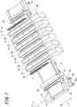
- Fig. 1 illustrates the overall configuration of the printer of the first embodiment.
- the printer of the present embodiment performs a printing process on the surface of a medium 1 that is very large to have a lateral length of several meters and a length in the vertical direction (conveying direction) in the range of several tens of meters to several thousands of meters, and is continuously conveyed.
- a medium 1 for example, a cloth is used.
- the medium 1 is conveyed through a conveying path (conveying portion) 2.
- An upstream side conveying unit 41 is disposed on one end side (upstream side) of the conveying path 2, and the medium 1 conveyed from an unwinding unit (not illustrated) is sequentially sent to a plurality of print units 11, 12, 13, 14, 15, and 16.
- a downstream side conveying unit 54 is disposed on the other end side (downstream side) of the conveying path 2, and the medium 1 that passes through the plurality of print units 11, 12, 13, 14, 15, and 16 is sent to another unit at the subsequent stage (a drying machine and the like).
- the plurality of print units 11, 12, 13, 14, 15, and 16 are disposed at fixed intervals.
- ink jet mechanisms with different colors are respectively disposed, and the printing process is performed on the surface of the medium 1 by the ink jet mechanisms. It should be noted that six print units 11 to 16 are disposed here, but the number of print units disposed is different according to the application of the printer.
- a medium inspection unit 51 is disposed in the conveying path 2 between the print unit 16 on the most downstream side and a downstream side conveying unit 54.
- the medium inspection unit 51 reads and inspects the image printed on the medium 1.
- an operation panel 61 and a display panel 62 are disposed, and various settings related to the printed state can be performed by the operation panel 61.
- the display panel 62 On the display panel 62, the operated state and the like of the printer are displayed.
- the direction in which the medium 1 is traveled on the conveying path 2 is an x direction
- the lateral width direction of the medium 1 is a y direction
- the perpendicular direction perpendicular to the medium 1 on the conveying path 2 is a z direction.
- work platforms 21 to 27 are disposed adjacent to the respective print units 11, 12, 13, 14, 15, and 16 and above the conveying path 2.
- the work platform 21 is disposed adjacent to the upstream side of the print unit 11, and the work platform 22 is disposed between the print unit 11 and the print unit 12.
- the work platform 23 is disposed between the print unit 12 and the print unit 13, and the work platform 24 is disposed between the print unit 13 and the print unit 14.
- the work platform 25 is disposed between the print unit 14 and the print unit 15, and the work platform 26 is disposed between the print unit 15 and the print unit 16.
- the work platform 27 is disposed adjacent to the downstream side of the print unit 16.
- a handrail 31 is provided at the end of the work platform 21 away from the print unit 11, and among these work platforms 21 to 27, for the work platform 27 on the most downstream side, a handrail 32 is provided at the end of the work platform 27 away from the print unit 16.
- a medium supply unit 41 includes a supply unit work platform 42, and the medium inspection unit 51 includes an inspection unit work platform 52.
- the supply unit work platform 42 also includes a handrail 43, and the inspection unit work platform 52 also includes a handrail 53.
- each of the work platforms 21 to 27, 42, and 52 are stands that an operator mounts during the maintenance and inspection operation for the respective units 11 to 16, 41, and 51. Therefore, each of the work platforms 21 to 27, 42, and 52 has a width to the extent that one person mounts it (for example, approximately 60 cm).
- the respective work platforms 21 to 27 disposed above the conveying path 2 include opening and closing mechanisms.
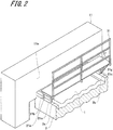
- Fig. 2 is a perspective view illustrating the configuration of the work platform 21 disposed adjacent to an exterior cover side face 11a on one side of the print unit 11.
- Fig. 3 is a diagram of two work platforms 21 and 22 disposed adjacent to the print unit 11, seen from the front.
- the work platform 21 illustrated in Figs. 2 and 3 is in the closed state, and the operator can mount the work platform 21.
- the work platform 22 illustrated in Fig. 3 is also in the closed state.
- the exterior cover side face 11a of the print unit 11 is opened and closed in a portion thereof, an exterior cover side face 11b of the print unit 11 is opened and closed in a portion thereof, and the operator who mounts the work platform 21 or 22 can see the interior of the print unit 11. It should be noted that the illustration of the mechanisms in which the portion of the exterior cover side face 11a and the portion of the exterior cover side face 11b are opened is omitted.
- the work platform 21 is installed on a frame configured of legs 21a, 21b, 21c, and 21d and beams 21e, 21f, 21g, and 21h. It should be noted that in Fig. 2 , some legs and beams are hidden by the work platform 21, but in Fig. 4 illustrating the work platform 21 in the opened state, all the legs and beams are seen.
- the lower ends of the respective legs 21a and 21b are coupled to a left edge 2a of the conveying path 2, and the lower ends of the respective legs 21c and 21d are coupled to a right edge 2b of the conveying path 2.
- the handrail 31 is coupled to the legs 21a, 21b, 21c, and 21d and the beams 21e, 21f, 21g, and 21h, and is not coupled to the work platform 21.
- the work platform 22 has the same configuration as the work platform 21 and includes leg portions 22a and 22b.
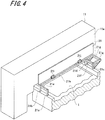
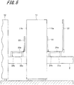
- Figs. 4 and 5 each illustrate an example when the work platform 21 is brought into the opened state.
- the illustration of the handrail 31 is omitted, but also when the work platform 21 is in the opened state, as illustrated in Fig. 5 , the handrail 31 is disposed at the same position as the case where the work platform 21 is in the closed state.
- the work platform 21 is coupled to the beam 21h by hinges 21i and 21j, and with the turning axes (not illustrated) of the hinges 21i and 21j as turning fulcrums, the work platform 21 can be moved from the position where the work platform 21 is disposed in the horizontal plane parallel to the plane of the medium 1 as illustrated in Fig. 2 (the closed state) to the position where the work platform 21 is disposed in the perpendicular plane perpendicular to the medium 1 (the opened state).
- the movement of the work platform 21 may be performed manually by the operator, but some driving mechanism may be mounted. An example in which the driving mechanism is mounted will be described in other embodiments described later.
- the work platform 21 brought into the opened state is at the position where the work platform 21 is almost erected right in front of the exterior cover side face 11a of the print unit 11.
- the work platform 22 adjacent to the exterior cover side face 11b on the opposite side of the print unit 11 can also be moved into the opened state, as illustrated in Fig. 5 .
- a sensor 21q is mounted, and by this sensor 21q, the opening and closing of the work platform 21 is detected.
- the detection signal of this sensor 21q is sent to the operation control unit (not illustrated) of the printer, and the operation of the printer is controlled on the basis of the detection signal of the sensor 21q. Specifically, when the sensor 21q detects the closed state of the work platform 21, the printer is stopped, and when the sensor 21q does not detect the closed state of the work platform 21, the printer is brought into the operable state.
- Fig. 6 enlargeably illustrates a portion of the work platform 21 brought into the opened state.
- a gutter 63 is disposed to be close to an end face 21x on the lower side of the work platform 21 brought into the opened state.
- the gutter 63 is disposed to have a length almost equal to the length of the work platform 21, and functions to collect dust falling from the work platform 21 and foreign substances left during the operation by a dust reception portion 64 inside the gutter 63.
- the printer of the present embodiment since the work platforms 21 to 27 are disposed adjacent to the print units 11 to 16, respectively, when the maintenance and inspection of the respective print units 11 to 16 are performed, the operator can perform the operation by mounting each of the work platforms 21 to 27, so that the operation efficiency can be improved.
- the respective work platforms 21 to 27 can be opened and closed by including the opening and closing mechanisms, so that by bringing the work platforms 21 to 27 into the opened state, the operator can directly visually inspect the state printed by the print units 11 to 16. Therefore, for example, when the operator adjusts the print unit 11, the printed state after the adjustment can be immediately read from the medium 1 conveyed to the downstream side of the print unit 11, so that the printed state can be inspected without increasing the downtime of the apparatus and the loss of the medium.
- the overall configuration of the printer of the second embodiment is the same as the printer illustrated in Fig. 1 in the first embodiment, and the opening and closing mechanism of the work platform is different from that of the first embodiment.
- Figs. 7 and 8 each illustrate the detailed configuration of the exterior cover side face 11a of a print unit 11' and a work platform 21' of the printer of the second embodiment.
- Fig. 7 illustrates the case where the work platform 21' is in the closed state
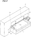
- Fig. 8 illustrates the case where the work platform 21' is in the opened state.
- the print unit 11' includes an opening 11c in the exterior cover side face 11a, which is different from the print unit 11 of the first embodiment.
- This opening 11c has a size that is almost equal to the size of the erected work platform 21'.
- the work platform 21' includes a mechanism in which it is opened and closed by being turned by the hinges 21i and 21j.
- the work platform 21' when being brought into the opened state to be brought into the erected state, the work platform 21' becomes the cover of the opening 11c.
- the work platform 21' By configuring the work platform 21' in this way, when as illustrated in Fig. 7 , the work platform 21' is brought into the closed state to be brought into the state where the operator can mount the work platform 21', the opening 11c of the print unit 11' is brought into the opened state, so that the maintenance and inspection of the interior 11d of the print unit 11' can be performed.
- the work platform 21' becomes the cover of the opening 11c of the exterior cover side face 11a, and the exterior cover side face 11a is brought into the closed state.
- the printer of the present embodiment by the opening and closing of the work platform 21', the state of the medium 1 can be inspected during the non-operation. Further, the opening 11c of the print unit 11' is changed between the opened state and the closed state in conjunction with the opening and closing of the work platform 21', and the interior of the print unit 11' can be automatically inspected by the operator.
- the opening and closing of the work platform 21' may be manually performed by the operator, but may be opened and closed by additionally providing a driving mechanism.
- Fig. 9 illustrates an example in which as the driving mechanism of the work platform 21', cylinders 71 and 72 are provided.
- the beam 21e and a coupling member 71b on the back face of the work platform 21' are coupled by the cylinder 71
- the beam 21g and a coupling member 72b on the back face of the work platform 21' are coupled by the cylinder 72.
- the work platform 21' is moved from the opened state into the closed state, or from the closed state into the opened state.
- Figs. 10 to 12 each illustrate an example in which as the driving mechanism of the work platform 21', windup machines 91 and 92 and wire members 91a and 92a are provided.
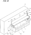
- Fig. 10 illustrates the state where the work platform 21' is closed
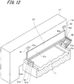
- Fig. 12 illustrates the state where the work platform 21' is opened.
- Fig. 11 illustrates the state while the work platform 21' is moved from the closed state into the opened state.
- a guide member 81 disposed in an L-shaped state along the moving path of the work platform 21' is provided, and at the right end of the work platform 21', a guide member 82 disposed in an L-shaped state along the moving path of the work platform 21' is provided.
- the inside of the guide member 82 has a guiding groove 82a, and the end of the work platform 21' is restricted to the movement along the guiding groove 82a.
- the other guide member 81 has the same guiding groove (not illustrated).
- the work platform 21' is coupled to the windup machine 91 via the wire member 91a, so that the wire member 91a is wound up by the windup machine 91, and the work platform 21' is coupled to the windup machine 92 via the wire member 92a, so that the wire member 92a is wound up by the windup machine 92, whereby as illustrated in Fig. 11 , the work platform 21' is gradually pulled upward. And, finally, as illustrated in Fig. 12 , the work platform 21' is moved to the position where it is fitted in the opening 11c of the exterior cover side face 11a of the print unit 11.
- the overall configuration of the printer of the third embodiment is the same as the printer illustrated in Fig. 1 in the first embodiment, and the opening and closing mechanism of the work platform is different from that of the first embodiment.
- Figs. 13 and 14 each illustrate the detailed configuration of the work platform of the third embodiment.
- work platforms 21-1 and 21-2 that are made by dividing the work platform 21 into two are provided.
- the work platforms 21-1 and 21-2 made by dividing the work platform 21 into two in the conveying direction of the medium 1 (the x direction illustrated in Fig. 1 ) are prepared, and the respective work platforms 21-1 and 21-2 can be individually opened and closed by the individual hinges (not illustrated).
- Fig. 14 illustrates the case where the respective work platforms 21-1 and 21-2 are brought into the opened state.
- Fig. 14 also illustrates work platforms 22-1 and 22-2 between the print unit 11 and the print unit 12.
- the respective work platforms 21-1, 21-2, 22-1, and 22-2 are brought into the erected state, so that the surface of the medium 1 on the conveying path 2 can be inspected.
- Fig. 14 illustrates the state where both of the work platforms 21-1 and 21-2 made by dividing the work platform 21 into two are opened, but only one of the work platforms 21-1 and 21-2 may be brought into the opened state.
- the driving mechanisms may be provided to both of the respective work platforms 21-1 and 21-2.
- the overall configuration of the printer of the fourth embodiment is the same as the printer illustrated in Fig. 1 in the first embodiment, and the opening and closing mechanism of the work platform is different from that of the first embodiment.
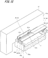
- Fig. 15 illustrates the detailed configuration of the work platform of the fourth embodiment.
- work platforms 21-11, 21-12, 21-13, and 21-14 made by dividing the work platform 21 into four are provided.
- the work platform 21 is divided into two in the conveying direction of the medium 1 (the x direction illustrated in Fig. 1 ), and is then divided into two in the width direction of the medium 1 (the y direction illustrated in Fig. 1 ), the work platforms 21-11, 21-12, 21-13, and 21-14 made by dividing the work platform 21 into four in total are prepared, and the respective work platforms 21-11, 21-12, 21-13, and 21-14 can be individually opened and closed by individual hinges 21m and 21n and the like.
- the size of the respective work platforms 21-11 to 21-14 is relatively small, and the operation in which the operator holds the work platforms 21-11 to 21-14 by hand and opens and closes them can be easily performed.
- the operator can visually inspect the surface of a portion of the medium 1 in the state where he/she mounts another work platform 21-11, 21-13, or 21-14.
- the overall configuration of the printer of the fifth embodiment is the same as the printer illustrated in Fig. 1 in the first embodiment, and the opening and closing mechanism of the work platform is different from that of the first embodiment.
- Fig. 16 illustrates the detailed configuration of the work platform of the fifth embodiment.
- opening windows 21o and 21p are provided in the work platform 21.
- the opening windows 21o and 21p are provided, and can be opened and closed.
- Fig. 16 illustrates the opening window 21o in the closed state, and the opening window 21p in the opened state.
- opening windows 21o and 21p By providing the opening windows 21o and 21p in this way, while the operator mounts the work platform 21, he/she can visually inspect a portion of the surface of the medium 1 by the opening and closing of the opening windows 21o and 21p.
- the overall configuration of the printer of the sixth embodiment is the same as the printer illustrated in Fig. 1 in the first embodiment, and the supporting configuration of the work platform is different from that of the first embodiment.
- Fig. 17 illustrates the detailed configuration of the work platform of the sixth embodiment.
- legs 101, 102, and 103 supporting the work platform 21 are extended from the floor surface in the installation place of the printer. That is, the legs 101 and 102 supporting one of the ends of the work platform 21 are mounted on a base portion 110 installed on the floor. Also, the leg 103 supporting the other end of the work platform 21 is mounted on the base portion installed on the floor (not illustrated) in the same manner.
- the work platform 21 By configuring the work platform 21 in such a manner, the work platform 21 is supported on the floor surface on which the printer is installed.
- the printer in which the plurality of print units 11 to 16 are disposed is provided.
- the present invention may be applied to the printer in which only one print unit is disposed.
- the work platforms including the opening and closing mechanisms are disposed adjacent to one exterior cover side face and the other exterior cover side face of the one print unit.
- the work platform including only one unit opening and closing mechanism is disposed adjacent to one of the exterior cover side faces of the one print unit.
- all the work platforms 21 to 27 disposed adjacent to the respective print units 11 to 16 include the opening and closing mechanisms.
- some work platforms are not necessarily required to include the opening and closing mechanisms.
- the work platform 21 disposed on the most upstream side of the conveying path 2 of the medium 1 is not necessarily required to be provided with the opening and closing mechanism, and the opening and closing mechanisms may be provided to other work platforms 22 to 17.
- the sensor 21q ( Fig. 4 ) is provided, the opening and closing of the work platform 21 is detected by the detection signal of the sensor 21q, and when the work platform 21 is in the closed state, the operation of the printer is limited (stopped) to secure the safety of the operator.
- the same sensor may be provided to limit the operation of the printer by the detection signal of the sensor.
- the sensor is preferably provided to each divided work platform.
- the opening and closing position of the work platform may be detected from the driving state of these driving mechanisms.
- the driving mechanism of the work platform illustrated in the above-mentioned embodiments illustrates an example, and other driving mechanisms may be mounted.
- the driving mechanisms such as racks and pinions, converting the movement of the motor to straight movement may be provided.
- various driving sources such as an oil hydraulic motor, can be used.
- the exterior cover side face 11a of the print unit 11' is disposed to be in the state where it is erected to be perpendicular to the conveying direction of the medium 1, but the exterior cover side face 11a may be located at the different disposing position where for example, it is slightly tilted from the vertical state.
- the work platform is brought into the opened state to close the exterior cover side face 11a, the work platform is, to be exact, disposed at the position slightly shifted from the position where it is brought into the state perpendicular to the disposing plane of the medium 1, but is disposed at the position where it is brought into the state substantially perpendicular to the disposing plane of the medium 1.
- the work platform is changed 90° in position by being opened and closed, but the 90° change of the work platform in position in this way is an example, and the work platform is changed approximately 90° in position.
- the work platform when the work platform is brought from the closed state into the opened state, the work platform is turned, but the work platform may be opened and closed by being slid in the up-down direction and the like.
- a slide mechanism opening and closing mechanism in which the work platform can be raised and lowered in the up-down direction while holding the horizontal state parallel to the medium is provided, the state where the work platform is lowered by the slide mechanism to be close to the medium (the state where it is disposed in a first plane) may be the closed state, and the state where the work platform is raised to be away from the medium (the state where it is disposed in a third plane substantially parallel to the first plane and away from the medium) may be the opened state. That is, the mechanism in which the work platform is slid is also included in the opening and closing mechanism of the work platform described so far.
- the opening and closing mechanism in which the work platform can be slid while holding the horizontal state is provided in this way, so that when the work platform is slid into the third plane away from the medium, the operator can visually inspect the conveying face of the medium.
- the mechanism in which each of the divided individual work platforms is opened and closed may be the opening and closing mechanism (slide mechanism) in which each of the work platforms can be slid while holding the horizontal state.
- the mechanism in which the windows are opened and closed may be the opening and closing mechanism (slide mechanism) in which each work platform can be slid while holding the horizontal state.
- the mechanism in which the windows are opened and closed is the opening and closing mechanism in which each work platform can be slid
- the work platform can be raised and lowered by, for example, the windup of the wire member 91a by the windup machine 91 illustrated in Fig. 10 and the windup of the wire member 92a by the windup machine 92 illustrated in Fig. 10 .
- the work platform may be slid in the up-down direction by other driving mechanisms.
- the work platform may be slid in the up-down direction by the driving mechanism, such as the cylinders, performing straight movement.
- the printer performs printing by the ink jet mechanisms as the respective print units 11 to 16, but may be of other various types.
- the work platform installed in the printer is brought into the closed state, so that the operator can mount the work platform to perform an operation, such as adjustment, and the work platform is brought into the opened state, so that the surface of the medium immediately after the medium is printed by the print unit can be visually inspected, whereby the operativity during the adjustment of the printer can be improved.
Landscapes
- Accessory Devices And Overall Control Thereof (AREA)
Abstract
In a large printer including a work platform, the state of printing to a medium is preferably inspected without being interfered by the work platform. The printer includes a print unit 11 that performs a printing process to a medium 1, a conveying portion 2 that conveys the medium 1 so that the medium 1 passes through the print unit 11, and a work platform 21 disposed adjacent to the print unit 11 and above the conveying portion 2. Here, the work platform 21 is provided with an opening and closing mechanism, and can be opened and closed.
Description
- The entire disclosure of Japanese Patent Application No.
2019-26362, filed on Feb. 18, 2019 - The present invention relates to a printer. More specifically, the present invention relates to a technology applied to a large printer including a work platform for maintenance and inspection.
- Various large industrial printers that enable printing on very large media having a lateral width of several meters (cloths, sheets, and the like) have been developed. By using such large printers to perform printing on the cloths and the like, for example, various interior products on which desired design is printed can be manufactured. The products manufactured by using the large printers are often relatively expensive, and require high quality printing without printing failure and the like.
- Therefore, for the large industrial printer, a work platform is disposed adjacent to the print unit to perform the maintenance of the apparatus. This work platform is typically installed so as to straddle over the conveying path of the medium to be printed. An operator mounts the work platform disposed adjacent to the print unit, and can execute the maintenance of the interior of the print unit, so that the operativity during the maintenance of the large printer is improved.
- Patent Literature 1 (Japanese Unexamined Patent Application Publication No.
2016-2675 - Patent Literature 1: Japanese Unexamined Patent Application Publication No.
2016-2675 - By disposing the work platform adjacent to the print unit, the operativity of the inspection and adjustment of the interior of the print unit can be improved, but there is a problem that the work platform interferes with the visual inspection of the surface of the medium to be printed. That is, when the operator inspects the printed state, it is important to visually inspect the surface of the medium immediately after the medium is printed by the print unit.
- For example, when the operator performs some adjustment for the print unit and desires to inspect whether printing after the adjustment is properly performed, he/she inspects the medium surface on the downstream side of the conveying path of the printed medium. Here, when the printed state of the medium immediately after the medium is printed by the print unit can be inspected, re-adjustment can be immediately performed in the event that the adjusted state is not proper, so that the waste of the medium and the ink can be minimized.
- However, when as described above, the work platform is disposed adjacent to the print unit, there is a problem that the inspection of the medium printed by the print unit is interfered by the work platform, and cannot be performed unless the medium is in the state where it is moved toward the downstream side to some degree. When the distance from the printing position in the print unit to the position where the surface of the medium can be inspected is long, the entire printing from the printing position to the inspecting position is wasted in the event that the adjusted state is not proper.
- An object of the present invention is to preferably inspect, in a large printer including a work platform, the state of printing to a medium without being interfered by the work platform.
- To achieve at least the abovementioned object, according to one aspect of the present invention, a printer reflecting one aspect of the present invention comprises a print unit that performs a printing process to a medium, a conveying portion that conveys the medium so that the medium passes through the print unit, and a work platform disposed adjacent to the print unit and above the conveying portion and having an opening and closing mechanism.
- The advantages and features provided by one or more embodiments of the invention will become more fully understood from the detailed description given hereinbelow and the appended drawings which are given by way of illustration only, and thus are not intended as a definition of the limits of the present invention:
-
Fig. 1 is a perspective view illustrating the overall configuration example of a printer according to a first embodiment of the present invention; -
Fig. 2 is a perspective view illustrating the configuration example of the essential part of the printer according to the first embodiment of the present invention; -
Fig. 3 is a front view illustrating the configuration example of the essential part of the printer according to the first embodiment of the present invention; -
Fig. 4 is a perspective view illustrating an example of the state where a work platform of the printer is opened according to the first embodiment of the present invention; -
Fig. 5 is a front view illustrating an example of the state where the work platform of the printer is opened according to the first embodiment of the present invention; -
Fig. 6 is a perspective view illustrating an example of a gutter disposed near the work platform of the printer according to the first embodiment of the present invention; -
Fig. 7 is a perspective view illustrating the configuration example of the essential part of the printer (the state where the work platform is in the closed state) according to a second embodiment of the present invention; -
Fig. 8 is a perspective view illustrating the configuration example of the essential part of the printer (the state where the work platform is in the opened state) according to the second embodiment of the present invention; -
Fig. 9 is a perspective view illustrating an example in which a driving mechanism is provided to the work platform of the printer (Example 1) according to the second embodiment of the present invention; -
Fig. 10 is a perspective view illustrating an example in which a driving mechanism is provided to the work platform of the printer (Example 2: The work platform is in the closed state.) according to the second embodiment of the present invention; -
Fig. 11 is a perspective view illustrating an example in which the driving mechanism is provided to the work platform of the printer (Example 2: The work platform is in the state where it is being driven.) according to the second embodiment of the present invention; -
Fig. 12 is a perspective view illustrating an example in which the driving mechanism is provided to the work platform of the printer (Example 2: The work platform is in the opened state.) according to the second embodiment of the present invention; -
Fig. 13 is a perspective view illustrating the configuration example of the essential part of the printer (The work platform is in the closed state.) according to a third embodiment of the present invention; -
Fig. 14 is a front view illustrating the configuration example of the essential part of the printer (The work platform is in the opened state.) according to the third embodiment of the present invention; -
Fig. 15 is a perspective view illustrating the configuration example of the essential part of the printer (One work platform is in the opened state.) according to a fourth embodiment of the present invention; -
Fig. 16 is a perspective view illustrating the configuration example of the essential part of the printer according to a fifth embodiment of the present invention; and -
Fig. 17 is a perspective view illustrating the configuration example of the essential part of the printer according to a sixth embodiment of the present invention. - Embodiments of the present invention will be described below with reference to the accompanying drawings. However, the scope of the invention is not limited to the disclosed embodiments. In the respective embodiments described below, shared portions are indicated by the same reference numerals and the overlapped description thereof is omitted.
- First, a printer of a first embodiment will be described with reference to
Figs. 1 to 6 . -
Fig. 1 illustrates the overall configuration of the printer of the first embodiment. - The printer of the present embodiment performs a printing process on the surface of a
medium 1 that is very large to have a lateral length of several meters and a length in the vertical direction (conveying direction) in the range of several tens of meters to several thousands of meters, and is continuously conveyed. As themedium 1, for example, a cloth is used. - The
medium 1 is conveyed through a conveying path (conveying portion) 2. An upstreamside conveying unit 41 is disposed on one end side (upstream side) of theconveying path 2, and themedium 1 conveyed from an unwinding unit (not illustrated) is sequentially sent to a plurality ofprint units - Also, a downstream
side conveying unit 54 is disposed on the other end side (downstream side) of theconveying path 2, and themedium 1 that passes through the plurality ofprint units - Here, in the middle of the
conveying path 2 on which themedium 1 is conveyed, the plurality ofprint units respective print units 11 to 16, ink jet mechanisms with different colors are respectively disposed, and the printing process is performed on the surface of themedium 1 by the ink jet mechanisms. It should be noted that sixprint units 11 to 16 are disposed here, but the number of print units disposed is different according to the application of the printer. - Also, in the
conveying path 2 between theprint unit 16 on the most downstream side and a downstreamside conveying unit 54, amedium inspection unit 51 is disposed. Themedium inspection unit 51 reads and inspects the image printed on themedium 1. - Also, beside the conveying
path 2, anoperation panel 61 and adisplay panel 62 are disposed, and various settings related to the printed state can be performed by theoperation panel 61. On thedisplay panel 62, the operated state and the like of the printer are displayed. - It should be noted that in the following description, the direction in which the
medium 1 is traveled on the conveyingpath 2 is an x direction, the lateral width direction of themedium 1 is a y direction, and the perpendicular direction perpendicular to the medium 1 on the conveyingpath 2 is a z direction. - And, in the printer of the present embodiment,
work platforms 21 to 27 are disposed adjacent to therespective print units path 2. - Specifically, the
work platform 21 is disposed adjacent to the upstream side of theprint unit 11, and thework platform 22 is disposed between theprint unit 11 and theprint unit 12. - The
work platform 23 is disposed between theprint unit 12 and theprint unit 13, and thework platform 24 is disposed between theprint unit 13 and theprint unit 14. - Also, the
work platform 25 is disposed between theprint unit 14 and theprint unit 15, and thework platform 26 is disposed between theprint unit 15 and theprint unit 16. - Further, the
work platform 27 is disposed adjacent to the downstream side of theprint unit 16. - Among these
work platforms 21 to 27, for thework platform 21 on the most upstream side, ahandrail 31 is provided at the end of thework platform 21 away from theprint unit 11, and among thesework platforms 21 to 27, for thework platform 27 on the most downstream side, ahandrail 32 is provided at the end of thework platform 27 away from theprint unit 16. - Also, for the printer of the present embodiment, as illustrated in
Fig. 1 , amedium supply unit 41 includes a supplyunit work platform 42, and themedium inspection unit 51 includes an inspectionunit work platform 52. The supplyunit work platform 42 also includes ahandrail 43, and the inspectionunit work platform 52 also includes ahandrail 53. - The
respective work platforms 21 to 27, 42, and 52 are stands that an operator mounts during the maintenance and inspection operation for therespective units 11 to 16, 41, and 51. Therefore, each of thework platforms 21 to 27, 42, and 52 has a width to the extent that one person mounts it (for example, approximately 60 cm). - The
respective work platforms 21 to 27 disposed above the conveyingpath 2 include opening and closing mechanisms. - All the opening and closing mechanisms included in the
work platforms 21 to 27 have the same configuration, and in the following description, thework platform 21 will be described as a representative example. -
Fig. 2 is a perspective view illustrating the configuration of thework platform 21 disposed adjacent to an exteriorcover side face 11a on one side of theprint unit 11. Also,Fig. 3 is a diagram of twowork platforms print unit 11, seen from the front. - The
work platform 21 illustrated inFigs. 2 and3 is in the closed state, and the operator can mount thework platform 21. Thework platform 22 illustrated inFig. 3 is also in the closed state. - The exterior
cover side face 11a of theprint unit 11 is opened and closed in a portion thereof, an exteriorcover side face 11b of theprint unit 11 is opened and closed in a portion thereof, and the operator who mounts thework platform print unit 11. It should be noted that the illustration of the mechanisms in which the portion of the exteriorcover side face 11a and the portion of the exteriorcover side face 11b are opened is omitted. - The
work platform 21 is installed on a frame configured oflegs beams Fig. 2 , some legs and beams are hidden by thework platform 21, but inFig. 4 illustrating thework platform 21 in the opened state, all the legs and beams are seen. - The lower ends of the
respective legs left edge 2a of the conveyingpath 2, and the lower ends of therespective legs path 2. Also, thehandrail 31 is coupled to thelegs beams work platform 21. Thework platform 22 has the same configuration as thework platform 21 and includesleg portions -
Figs. 4 and5 each illustrate an example when thework platform 21 is brought into the opened state. InFig. 4 , the illustration of thehandrail 31 is omitted, but also when thework platform 21 is in the opened state, as illustrated inFig. 5 , thehandrail 31 is disposed at the same position as the case where thework platform 21 is in the closed state. - The
work platform 21 is coupled to thebeam 21h byhinges hinges work platform 21 can be moved from the position where thework platform 21 is disposed in the horizontal plane parallel to the plane of the medium 1 as illustrated inFig. 2 (the closed state) to the position where thework platform 21 is disposed in the perpendicular plane perpendicular to the medium 1 (the opened state). The movement of thework platform 21 may be performed manually by the operator, but some driving mechanism may be mounted. An example in which the driving mechanism is mounted will be described in other embodiments described later. - As illustrated in
Fig. 5 , thework platform 21 brought into the opened state is at the position where thework platform 21 is almost erected right in front of the exteriorcover side face 11a of theprint unit 11. - Also, the
work platform 22 adjacent to the exteriorcover side face 11b on the opposite side of theprint unit 11 can also be moved into the opened state, as illustrated inFig. 5 . - As illustrated in
Fig. 4 , when thework platform 21 is brought into the opened state, the medium 1 in the portion adjacent to theprint unit 11 is exposed. Therefore, the operator can inspect the state of the surface of themedium 1. - It should be noted that on the
beam 21g, a sensor 21q is mounted, and by this sensor 21q, the opening and closing of thework platform 21 is detected. The detection signal of this sensor 21q is sent to the operation control unit (not illustrated) of the printer, and the operation of the printer is controlled on the basis of the detection signal of the sensor 21q. Specifically, when the sensor 21q detects the closed state of thework platform 21, the printer is stopped, and when the sensor 21q does not detect the closed state of thework platform 21, the printer is brought into the operable state. -
Fig. 6 enlargeably illustrates a portion of thework platform 21 brought into the opened state. - In the printer of the present embodiment, a
gutter 63 is disposed to be close to anend face 21x on the lower side of thework platform 21 brought into the opened state. Thegutter 63 is disposed to have a length almost equal to the length of thework platform 21, and functions to collect dust falling from thework platform 21 and foreign substances left during the operation by adust reception portion 64 inside thegutter 63. - By disposing this
gutter 63, the dust falling from thework platform 21 brought into the opened state can be prevented from falling onto the medium 1 on the conveyingpath 2. - As described above, according to the printer of the present embodiment, since the
work platforms 21 to 27 are disposed adjacent to theprint units 11 to 16, respectively, when the maintenance and inspection of therespective print units 11 to 16 are performed, the operator can perform the operation by mounting each of thework platforms 21 to 27, so that the operation efficiency can be improved. - And, the
respective work platforms 21 to 27 can be opened and closed by including the opening and closing mechanisms, so that by bringing thework platforms 21 to 27 into the opened state, the operator can directly visually inspect the state printed by theprint units 11 to 16. Therefore, for example, when the operator adjusts theprint unit 11, the printed state after the adjustment can be immediately read from the medium 1 conveyed to the downstream side of theprint unit 11, so that the printed state can be inspected without increasing the downtime of the apparatus and the loss of the medium. - Next, a second embodiment of the present invention will be described with reference to
Figs. 7 to 12 . - The overall configuration of the printer of the second embodiment is the same as the printer illustrated in
Fig. 1 in the first embodiment, and the opening and closing mechanism of the work platform is different from that of the first embodiment. -
Figs. 7 and8 each illustrate the detailed configuration of the exteriorcover side face 11a of a print unit 11' and a work platform 21' of the printer of the second embodiment.Fig. 7 illustrates the case where the work platform 21' is in the closed state, andFig. 8 illustrates the case where the work platform 21' is in the opened state. - The print unit 11' includes an
opening 11c in the exteriorcover side face 11a, which is different from theprint unit 11 of the first embodiment. Thisopening 11c has a size that is almost equal to the size of the erected work platform 21'. - By providing the
opening 11c in the exteriorcover side face 11a in this way, when as illustrated inFig. 7 , the work platform 21' is in the closed state, an interior 11d of the print unit 11' is brought into the state where it is exposed from theopening 11c. - And, as illustrated in
Fig. 8 , the work platform 21' includes a mechanism in which it is opened and closed by being turned by thehinges opening 11c. - It should be noted that here, only the configuration of the work platform 21' disposed adjacent to the print unit 11' has been described, but other work platforms included in the printer (the
work platforms 22 to 27 illustrated inFig. 1 ) are configured in the same manner. - By configuring the work platform 21' in this way, when as illustrated in
Fig. 7 , the work platform 21' is brought into the closed state to be brought into the state where the operator can mount the work platform 21', theopening 11c of the print unit 11' is brought into the opened state, so that the maintenance and inspection of the interior 11d of the print unit 11' can be performed. - On the other hand, when as illustrated in
Fig. 8 , being brought into the opened state, the work platform 21' becomes the cover of theopening 11c of the exteriorcover side face 11a, and the exteriorcover side face 11a is brought into the closed state. - Therefore, according to the printer of the present embodiment, by the opening and closing of the work platform 21', the state of the medium 1 can be inspected during the non-operation. Further, the
opening 11c of the print unit 11' is changed between the opened state and the closed state in conjunction with the opening and closing of the work platform 21', and the interior of the print unit 11' can be automatically inspected by the operator. - The opening and closing of the work platform 21' may be manually performed by the operator, but may be opened and closed by additionally providing a driving mechanism.
-
Fig. 9 illustrates an example in which as the driving mechanism of the work platform 21',cylinders - In the example illustrated in
Fig. 9 , thebeam 21e and acoupling member 71b on the back face of the work platform 21' are coupled by thecylinder 71, and thebeam 21g and acoupling member 72b on the back face of the work platform 21' are coupled by thecylinder 72. And, by the straight extension and contraction of ashaft 71a of thecylinder 71 and ashaft 72a of thecylinder 72, the work platform 21' is moved from the opened state into the closed state, or from the closed state into the opened state. -
Figs. 10 to 12 each illustrate an example in which as the driving mechanism of the work platform 21',windup machines wire members Fig. 10 illustrates the state where the work platform 21' is closed, andFig. 12 illustrates the state where the work platform 21' is opened. Also,Fig. 11 illustrates the state while the work platform 21' is moved from the closed state into the opened state. - In the example illustrated in
Fig. 10 , at the left end of the work platform 21', aguide member 81 disposed in an L-shaped state along the moving path of the work platform 21' is provided, and at the right end of the work platform 21', aguide member 82 disposed in an L-shaped state along the moving path of the work platform 21' is provided. The inside of theguide member 82 has a guidinggroove 82a, and the end of the work platform 21' is restricted to the movement along the guidinggroove 82a. Theother guide member 81 has the same guiding groove (not illustrated). - As illustrated in
Fig. 10 , the work platform 21' is coupled to thewindup machine 91 via thewire member 91a, so that thewire member 91a is wound up by thewindup machine 91, and the work platform 21' is coupled to thewindup machine 92 via thewire member 92a, so that thewire member 92a is wound up by thewindup machine 92, whereby as illustrated inFig. 11 , the work platform 21' is gradually pulled upward. And, finally, as illustrated inFig. 12 , the work platform 21' is moved to the position where it is fitted in theopening 11c of the exteriorcover side face 11a of theprint unit 11. - In the configuration illustrated in
Figs. 10 to 12 , when the work platform 21' is in the opened state (Fig. 12 ), asurface 21u of the work platform 21' is located outside the exteriorcover side face 11a. Therefore, in the event that there is dust on the work platform 21', the dust can be inhibited from entering into theprint unit 11. - Next, a third embodiment of the present invention will be described with reference to
Figs. 13 to 14 . - The overall configuration of the printer of the third embodiment is the same as the printer illustrated in
Fig. 1 in the first embodiment, and the opening and closing mechanism of the work platform is different from that of the first embodiment. -
Figs. 13 and14 each illustrate the detailed configuration of the work platform of the third embodiment. - In the third embodiment, work platforms 21-1 and 21-2 that are made by dividing the
work platform 21 into two are provided. - That is, as illustrated in
Fig. 13 , the work platforms 21-1 and 21-2 made by dividing thework platform 21 into two in the conveying direction of the medium 1 (the x direction illustrated inFig. 1 ) are prepared, and the respective work platforms 21-1 and 21-2 can be individually opened and closed by the individual hinges (not illustrated). -
Fig. 14 illustrates the case where the respective work platforms 21-1 and 21-2 are brought into the opened state.Fig. 14 also illustrates work platforms 22-1 and 22-2 between theprint unit 11 and theprint unit 12. - As illustrated in
Fig. 14 , the respective work platforms 21-1, 21-2, 22-1, and 22-2 are brought into the erected state, so that the surface of the medium 1 on the conveyingpath 2 can be inspected. - It should be noted that
Fig. 14 illustrates the state where both of the work platforms 21-1 and 21-2 made by dividing thework platform 21 into two are opened, but only one of the work platforms 21-1 and 21-2 may be brought into the opened state. - Also, when the work platforms 21-1 and 21-2 are made by dividing the
work platform 21 into two, the driving mechanisms may be provided to both of the respective work platforms 21-1 and 21-2. - Next, a fourth embodiment of the present invention will be described with reference to
Fig. 15 . - The overall configuration of the printer of the fourth embodiment is the same as the printer illustrated in
Fig. 1 in the first embodiment, and the opening and closing mechanism of the work platform is different from that of the first embodiment. -
Fig. 15 illustrates the detailed configuration of the work platform of the fourth embodiment. - In the fourth embodiment, work platforms 21-11, 21-12, 21-13, and 21-14 made by dividing the
work platform 21 into four are provided. - That is, as illustrated in
Fig. 15 , thework platform 21 is divided into two in the conveying direction of the medium 1 (the x direction illustrated inFig. 1 ), and is then divided into two in the width direction of the medium 1 (the y direction illustrated inFig. 1 ), the work platforms 21-11, 21-12, 21-13, and 21-14 made by dividing thework platform 21 into four in total are prepared, and the respective work platforms 21-11, 21-12, 21-13, and 21-14 can be individually opened and closed byindividual hinges - According to the configuration illustrated in
Fig. 15 , the size of the respective work platforms 21-11 to 21-14 is relatively small, and the operation in which the operator holds the work platforms 21-11 to 21-14 by hand and opens and closes them can be easily performed. Alternatively, when as illustrated inFig. 15 , only one work platform 21-12 is brought into the opened state, the operator can visually inspect the surface of a portion of the medium 1 in the state where he/she mounts another work platform 21-11, 21-13, or 21-14. - Next, a fifth embodiment of the present invention will be described with reference to
Fig. 16 . - The overall configuration of the printer of the fifth embodiment is the same as the printer illustrated in
Fig. 1 in the first embodiment, and the opening and closing mechanism of the work platform is different from that of the first embodiment. -
Fig. 16 illustrates the detailed configuration of the work platform of the fifth embodiment. - In the fifth embodiment, opening
windows 21o and 21p are provided in thework platform 21. - That is, as illustrated in
Fig. 16 , in the middle of thework platform 21, theopening windows 21o and 21p are provided, and can be opened and closed. - The example of
Fig. 16 illustrates the opening window 21o in the closed state, and theopening window 21p in the opened state. - By providing the
opening windows 21o and 21p in this way, while the operator mounts thework platform 21, he/she can visually inspect a portion of the surface of the medium 1 by the opening and closing of theopening windows 21o and 21p. - Next, a sixth embodiment of the present invention will be described with reference to
Fig. 17 . - The overall configuration of the printer of the sixth embodiment is the same as the printer illustrated in
Fig. 1 in the first embodiment, and the supporting configuration of the work platform is different from that of the first embodiment. -
Fig. 17 illustrates the detailed configuration of the work platform of the sixth embodiment. - In the sixth embodiment,
legs work platform 21 are extended from the floor surface in the installation place of the printer. That is, thelegs work platform 21 are mounted on abase portion 110 installed on the floor. Also, theleg 103 supporting the other end of thework platform 21 is mounted on the base portion installed on the floor (not illustrated) in the same manner. - By configuring the
work platform 21 in such a manner, thework platform 21 is supported on the floor surface on which the printer is installed. - It should be noted that in the above-mentioned embodiments, the printer in which the plurality of
print units 11 to 16 are disposed is provided. On the contrary, the present invention may be applied to the printer in which only one print unit is disposed. When only one print unit is disposed, the work platforms including the opening and closing mechanisms are disposed adjacent to one exterior cover side face and the other exterior cover side face of the one print unit. Alternatively, the work platform including only one unit opening and closing mechanism is disposed adjacent to one of the exterior cover side faces of the one print unit. - Also, in the above-mentioned embodiments, all the
work platforms 21 to 27 disposed adjacent to therespective print units 11 to 16 include the opening and closing mechanisms. On the contrary, some work platforms are not necessarily required to include the opening and closing mechanisms. For example, thework platform 21 disposed on the most upstream side of the conveyingpath 2 of themedium 1 is not necessarily required to be provided with the opening and closing mechanism, and the opening and closing mechanisms may be provided toother work platforms 22 to 17. - Also, in the first embodiment, the sensor 21q (
Fig. 4 ) is provided, the opening and closing of thework platform 21 is detected by the detection signal of the sensor 21q, and when thework platform 21 is in the closed state, the operation of the printer is limited (stopped) to secure the safety of the operator. For this, also in the second to sixth embodiments, the same sensor may be provided to limit the operation of the printer by the detection signal of the sensor. In the example in which the work platform is divided into two or four (Fig. 13 and the like), the sensor is preferably provided to each divided work platform. - Also, when the work platform is driven by the driving mechanisms, such as the windup machines and the cylinders, the opening and closing position of the work platform may be detected from the driving state of these driving mechanisms.
- Further, the driving mechanism of the work platform illustrated in the above-mentioned embodiments illustrates an example, and other driving mechanisms may be mounted. For example, instead of the cylinders, the driving mechanisms, such as racks and pinions, converting the movement of the motor to straight movement may be provided. For the driving source included in the driving mechanism, in addition to the electrically operated motor, various driving sources, such as an oil hydraulic motor, can be used.
- Also, in the second embodiment, as illustrated in
Fig. 9 , the exteriorcover side face 11a of the print unit 11' is disposed to be in the state where it is erected to be perpendicular to the conveying direction of themedium 1, but the exteriorcover side face 11a may be located at the different disposing position where for example, it is slightly tilted from the vertical state. In this case, when the work platform is brought into the opened state to close the exteriorcover side face 11a, the work platform is, to be exact, disposed at the position slightly shifted from the position where it is brought into the state perpendicular to the disposing plane of themedium 1, but is disposed at the position where it is brought into the state substantially perpendicular to the disposing plane of themedium 1. Also in other embodiments, the work platform is changed 90° in position by being opened and closed, but the 90° change of the work platform in position in this way is an example, and the work platform is changed approximately 90° in position. - Also, in the respective embodiments described so far, when the work platform is brought from the closed state into the opened state, the work platform is turned, but the work platform may be opened and closed by being slid in the up-down direction and the like. For example, a slide mechanism (opening and closing mechanism) in which the work platform can be raised and lowered in the up-down direction while holding the horizontal state parallel to the medium is provided, the state where the work platform is lowered by the slide mechanism to be close to the medium (the state where it is disposed in a first plane) may be the closed state, and the state where the work platform is raised to be away from the medium (the state where it is disposed in a third plane substantially parallel to the first plane and away from the medium) may be the opened state. That is, the mechanism in which the work platform is slid is also included in the opening and closing mechanism of the work platform described so far.
- The opening and closing mechanism in which the work platform can be slid while holding the horizontal state is provided in this way, so that when the work platform is slid into the third plane away from the medium, the operator can visually inspect the conveying face of the medium.
- Further, when as illustrated in
Figs. 13 and15 , the work platform is divided, the mechanism in which each of the divided individual work platforms is opened and closed may be the opening and closing mechanism (slide mechanism) in which each of the work platforms can be slid while holding the horizontal state. - Still further, when as illustrated in
Fig. 16 , the windows are provided in each work platform, the mechanism in which the windows are opened and closed may be the opening and closing mechanism (slide mechanism) in which each work platform can be slid while holding the horizontal state. When the mechanism in which the windows are opened and closed is the opening and closing mechanism in which each work platform can be slid, the work platform can be raised and lowered by, for example, the windup of thewire member 91a by thewindup machine 91 illustrated inFig. 10 and the windup of thewire member 92a by thewindup machine 92 illustrated inFig. 10 . Alternatively, the work platform may be slid in the up-down direction by other driving mechanisms. Also, alternatively, the work platform may be slid in the up-down direction by the driving mechanism, such as the cylinders, performing straight movement. - Also, in the above-mentioned embodiments, the printer performs printing by the ink jet mechanisms as the
respective print units 11 to 16, but may be of other various types. - According to the present invention, the work platform installed in the printer is brought into the closed state, so that the operator can mount the work platform to perform an operation, such as adjustment, and the work platform is brought into the opened state, so that the surface of the medium immediately after the medium is printed by the print unit can be visually inspected, whereby the operativity during the adjustment of the printer can be improved.
- Although embodiments of the present invention have been described and illustrated in detail, the disclosed embodiments are made for purposes of illustration and example only and not limitation. The scope of the present invention should be interpreted by terms of the appended claims.
- 1 ... medium, 2 ... conveying path, 2a, 2b ... edge, 11 to 16, 11' ... print unit, 11a, 11b ... exterior cover side face, 11c ... opening, 11d ... interior, 21 to 27, 21', 21-1, 21-2, 22-1, 22-2, 21-11, 21-12, 21-13, 21-14 ... work platform, 21a, 21b, 21c, 21d ... leg, 21e, 21f, 21g, 21h ... beam, 21i, 21j, 21m, 21n ... hinge, 21o, 21p ... opening window, 21q ... sensor, 21x ... end face, 21u ... surface, 22a, 22b ... leg, 31, 32 ... handrail, 41 ... upstream side conveying unit, 42 ... supply unit work platform, 43 ... handrail, 51 ... medium inspection unit, 52 ... inspection unit work platform, 53 ... handrail, 54 ... downstream side conveying unit, 61 ... operation panel, 62 ... display panel, 63 ... gutter, 64 ... dust reception portion, 71, 72 ... cylinder, 71a, 72a ... shaft, 71b, 72b ... coupling portion, 81, 82 ... guide member, 82a ... guiding groove, 91, 92 ... windup machine, 91a, 92a ... wire member, 101 to 103 ... leg, 110 ... base portion
Claims (15)
- A printer comprising:a print unit (11) that performs a printing process to a medium;a conveying portion (2) that conveys the medium so that the medium passes through the print unit (11); anda work platform (21) disposed adjacent to the print unit (11) and above the conveying portion (2) and having an opening and closing mechanism.
- The printer according to claim 1,
wherein when being brought into the closed state by the opening and closing mechanism, the work platform (21) is disposed in a first plane parallel to the medium conveyed through the conveying portion (2),
wherein when being brought into the opened state by the opening and closing mechanism, the work platform (21) is disposed in a second plane substantially perpendicular to the first plane. - The printer according to claim 2,
wherein the turning shafts of the opening and closing mechanism are disposed at the portions in which the first plane and the second plane are substantially perpendicular to each other, and the work platform (21) is opened and closed about the turning shafts. - The printer according to claim 2,
wherein the opening and closing mechanism includes a guide member (81, 82) that slides the work platform (21) from the first plane into the second plane. - The printer according to claim 1,
wherein the opening and closing mechanism is a slide mechanism in which the work platform (21) is raised and lowered in the up-down direction,
wherein the state where the work platform (21) is lowered by the slide mechanism to be disposed in the first plane close to the medium is the closed state, and the state where the work platform (21) is raised to be disposed in a third plane substantially parallel to the first plane and away from the medium is the opened state. - The printer according to claim 4 or 5,
wherein the printer includes a wire member (91a, 92a) coupled to the end of the work platform (21),
wherein the printer includes a driving portion (91, 92) winding the wire member (91a, 92a),
wherein by the winding of the wire member (91a, 92a) by the driving portion (91, 92), the work platform (21) is slid from the first plane into the second plane or the third plane. - The printer according to claim 2,
wherein the printer includes a driving portion (71, 72) that moves the work platform (21) from the first plane into the second plane by straight movement. - The printer according to claim 2,
wherein when the work platform (21) is brought into the opened state by the opening and closing mechanism, the work platform (21) closes an opening (11c) of an exterior cover of the print unit (1). - The printer according to claim 8,
wherein when the work platform (21) is brought into the opened state, the surface of the work platform (21) is disposed on the surface side of the exterior cover. - The printer according to claim 1,
wherein the printer includes a detection portion detecting that the work platform (21) is in the opened state, and
wherein when the detection portion detects the opened state, the medium can be conveyed through the conveying portion (2). - The printer according to claim 1,
wherein a gutter (63) that is close to the lower end of the work platform (21) when the work platform (21) is brought into the opened state is disposed. - The printer according to claim 1,
wherein the work platform (21) is divided into a plurality of work platforms, and
wherein respective work platforms (21-1, 21-2) that are made by dividing the work platform (21) into the plurality of work platforms can be individually opened and closed or slid by the opening and closing mechanism. - The printer according to claim 1,
wherein the work platform (21) includes a window (21o, 21p), and
wherein the window (21o, 21p) can be opened and closed or slid. - The printer according to claim 1,
wherein when being brought into the closed state by the opening and closing mechanism, the work platform (21) is supported by a supporting member (21a, 21b, 21c, 21d) coupled to the conveying portion (2). - The printer according to claim 1,
wherein when being brought into the closed state by the opening and closing mechanism, the work platform (21) is supported by a supporting member (101, 102, 103) coupled to a floor surface.
Applications Claiming Priority (1)
| Application Number | Priority Date | Filing Date | Title |
|---|---|---|---|
| JP2019026362A JP7271992B2 (en) | 2019-02-18 | 2019-02-18 | printer |
Publications (1)
| Publication Number | Publication Date |
|---|---|
| EP3695978A1 true EP3695978A1 (en) | 2020-08-19 |
Family
ID=68835121
Family Applications (1)
| Application Number | Title | Priority Date | Filing Date |
|---|---|---|---|
| EP19214417.8A Withdrawn EP3695978A1 (en) | 2019-02-18 | 2019-12-09 | Printer |
Country Status (2)
| Country | Link |
|---|---|
| EP (1) | EP3695978A1 (en) |
| JP (1) | JP7271992B2 (en) |
Citations (6)
| Publication number | Priority date | Publication date | Assignee | Title |
|---|---|---|---|---|
| US5003889A (en) * | 1989-02-22 | 1991-04-02 | Man Roland Druckmaschinen Ag | Rotary printing machine system with a web path changing arrangement |
| US5655448A (en) * | 1993-02-06 | 1997-08-12 | Heidelberger Druckmaschinen Ag | Safety device at a rotary printing machine |
| US5816157A (en) * | 1995-05-05 | 1998-10-06 | Maschinenfabrik Wifag | Rotary printing press with retractable rubber cylinders |
| US20130008744A1 (en) * | 2010-03-05 | 2013-01-10 | Koenig & Bauer Aktiengesellschaft | Printing tower of a press having a vertically movable platform and method for providing the platform |
| JP2016002675A (en) | 2014-06-16 | 2016-01-12 | コニカミノルタ株式会社 | Head unit and liquid ejection device |
| JP2017087433A (en) * | 2015-11-02 | 2017-05-25 | 株式会社小森コーポレーション | Sheet-like object inspection device |
Family Cites Families (5)
| Publication number | Priority date | Publication date | Assignee | Title |
|---|---|---|---|---|
| JPH05286512A (en) * | 1992-04-10 | 1993-11-02 | Daifuku Co Ltd | Article collecting device |
| JPH11301819A (en) * | 1998-04-17 | 1999-11-02 | Parutakku:Kk | Picking truck and method of sorting commodity on picking truck by stores |
| JP3938907B2 (en) * | 2002-12-26 | 2007-06-27 | 株式会社桜井グラフィックシステムズ | Printer |
| JP2008087360A (en) * | 2006-10-03 | 2008-04-17 | Mitsubishi Heavy Ind Ltd | Offset rotary press, and method and apparatus for replacing its printing plate |
| JP5346353B2 (en) * | 2011-05-13 | 2013-11-20 | ヤマハ発動機株式会社 | Substrate manufacturing apparatus and printing machine |
-
2019
- 2019-02-18 JP JP2019026362A patent/JP7271992B2/en active Active
- 2019-12-09 EP EP19214417.8A patent/EP3695978A1/en not_active Withdrawn
Patent Citations (6)
| Publication number | Priority date | Publication date | Assignee | Title |
|---|---|---|---|---|
| US5003889A (en) * | 1989-02-22 | 1991-04-02 | Man Roland Druckmaschinen Ag | Rotary printing machine system with a web path changing arrangement |
| US5655448A (en) * | 1993-02-06 | 1997-08-12 | Heidelberger Druckmaschinen Ag | Safety device at a rotary printing machine |
| US5816157A (en) * | 1995-05-05 | 1998-10-06 | Maschinenfabrik Wifag | Rotary printing press with retractable rubber cylinders |
| US20130008744A1 (en) * | 2010-03-05 | 2013-01-10 | Koenig & Bauer Aktiengesellschaft | Printing tower of a press having a vertically movable platform and method for providing the platform |
| JP2016002675A (en) | 2014-06-16 | 2016-01-12 | コニカミノルタ株式会社 | Head unit and liquid ejection device |
| JP2017087433A (en) * | 2015-11-02 | 2017-05-25 | 株式会社小森コーポレーション | Sheet-like object inspection device |
Also Published As
| Publication number | Publication date |
|---|---|
| JP7271992B2 (en) | 2023-05-12 |
| JP2020131517A (en) | 2020-08-31 |
Similar Documents
| Publication | Publication Date | Title |
|---|---|---|
| JP4856628B2 (en) | Device for in-line monitoring of print quality in a sheet-fed offset press | |
| US11618271B2 (en) | Ink-jet print heads protecting system in a digital printing machine | |
| CN1085963C (en) | Printing group for a colour-printing web-fed rotary press | |
| US10071554B2 (en) | Modular print engine unit | |
| US8237828B2 (en) | Device for inspection of print products | |
| TW201422448A (en) | Recording apparatus | |
| EP3695978A1 (en) | Printer | |
| JP5437005B2 (en) | Printing device | |
| TWI600548B (en) | An inkjet recording device | |
| KR20110061270A (en) | Nozzle of inkjet printer and gap adjusting device of printing object and printing method using same | |
| JP2013193218A (en) | Sheet conveyance device and image forming device | |
| JP2024501545A (en) | Inkjet head nozzle inspection equipment | |
| DE102010030789B4 (en) | Sheet inspection system | |
| JP2011110711A (en) | Inkjet apparatus | |
| CN114435999B (en) | Medium conveying mechanism | |
| CN217716772U (en) | Multi-line sampling detection equipment suitable for tire pressure sensor | |
| JP5314552B2 (en) | Printing device | |
| JP2005225041A (en) | Image recording device | |
| IT202100013085A1 (en) | APPARATUS AND METHOD FOR PAINTING PANELS BY ROLLER, PREFERABLE PHOTOVOLTAIC PANELS | |
| US11724902B2 (en) | Printing apparatus | |
| JP2017177495A (en) | Printed matter inspection method and apparatus | |
| CN215210137U (en) | Radial coil inspection machine | |
| CN218239870U (en) | Digital printing quality defect detection device | |
| KR102000943B1 (en) | An X-Ray Apparatus Having a Structure of Guiding a Transfer | |
| JP7336308B2 (en) | Sheet body inspection device |
Legal Events
| Date | Code | Title | Description |
|---|---|---|---|
| PUAI | Public reference made under article 153(3) epc to a published international application that has entered the european phase |
Free format text: ORIGINAL CODE: 0009012 |
|
| STAA | Information on the status of an ep patent application or granted ep patent |
Free format text: STATUS: THE APPLICATION HAS BEEN PUBLISHED |
|
| AK | Designated contracting states |
Kind code of ref document: A1 Designated state(s): AL AT BE BG CH CY CZ DE DK EE ES FI FR GB GR HR HU IE IS IT LI LT LU LV MC MK MT NL NO PL PT RO RS SE SI SK SM TR |
|
| AX | Request for extension of the european patent |
Extension state: BA ME |
|
| STAA | Information on the status of an ep patent application or granted ep patent |
Free format text: STATUS: THE APPLICATION IS DEEMED TO BE WITHDRAWN |
|
| 18D | Application deemed to be withdrawn |
Effective date: 20210220 |