EP3695681B1 - Espace de recherche de réponse de canal d'accès aléatoire (rach) dépendant d'une porteuse - Google Patents
Espace de recherche de réponse de canal d'accès aléatoire (rach) dépendant d'une porteuse Download PDFInfo
- Publication number
- EP3695681B1 EP3695681B1 EP18792808.0A EP18792808A EP3695681B1 EP 3695681 B1 EP3695681 B1 EP 3695681B1 EP 18792808 A EP18792808 A EP 18792808A EP 3695681 B1 EP3695681 B1 EP 3695681B1
- Authority
- EP
- European Patent Office
- Prior art keywords
- carrier
- uplink
- transmitted
- search space
- rach
- Prior art date
- Legal status (The legal status is an assumption and is not a legal conclusion. Google has not performed a legal analysis and makes no representation as to the accuracy of the status listed.)
- Active
Links
- 230000004044 response Effects 0.000 title claims description 14
- 230000001419 dependent effect Effects 0.000 title description 5
- 230000005540 biological transmission Effects 0.000 claims description 76
- 238000000034 method Methods 0.000 claims description 61
- 238000004891 communication Methods 0.000 claims description 57
- 239000000969 carrier Substances 0.000 claims description 17
- 238000004590 computer program Methods 0.000 claims description 7
- 238000012544 monitoring process Methods 0.000 claims description 3
- 238000005516 engineering process Methods 0.000 description 24
- 238000003860 storage Methods 0.000 description 14
- 230000006870 function Effects 0.000 description 13
- 238000012545 processing Methods 0.000 description 12
- 238000010586 diagram Methods 0.000 description 11
- 238000013461 design Methods 0.000 description 8
- 230000008569 process Effects 0.000 description 8
- 230000015654 memory Effects 0.000 description 7
- 230000009471 action Effects 0.000 description 5
- 230000002776 aggregation Effects 0.000 description 5
- 238000004220 aggregation Methods 0.000 description 5
- 230000000153 supplemental effect Effects 0.000 description 5
- 238000000926 separation method Methods 0.000 description 4
- 238000001228 spectrum Methods 0.000 description 4
- 230000001360 synchronised effect Effects 0.000 description 4
- 230000008685 targeting Effects 0.000 description 4
- 230000001413 cellular effect Effects 0.000 description 3
- 101100274486 Mus musculus Cited2 gene Proteins 0.000 description 2
- 101150096622 Smr2 gene Proteins 0.000 description 2
- 125000004122 cyclic group Chemical group 0.000 description 2
- 239000000835 fiber Substances 0.000 description 2
- 230000006872 improvement Effects 0.000 description 2
- 230000007774 longterm Effects 0.000 description 2
- 238000012986 modification Methods 0.000 description 2
- 230000004048 modification Effects 0.000 description 2
- 230000003287 optical effect Effects 0.000 description 2
- 230000008520 organization Effects 0.000 description 2
- 238000012546 transfer Methods 0.000 description 2
- 101000741965 Homo sapiens Inactive tyrosine-protein kinase PRAG1 Proteins 0.000 description 1
- 102100038659 Inactive tyrosine-protein kinase PRAG1 Human genes 0.000 description 1
- 101100533725 Mus musculus Smr3a gene Proteins 0.000 description 1
- 241000700159 Rattus Species 0.000 description 1
- 230000008901 benefit Effects 0.000 description 1
- 230000008878 coupling Effects 0.000 description 1
- 238000010168 coupling process Methods 0.000 description 1
- 238000005859 coupling reaction Methods 0.000 description 1
- 238000001514 detection method Methods 0.000 description 1
- 238000011161 development Methods 0.000 description 1
- 230000009977 dual effect Effects 0.000 description 1
- 230000002452 interceptive effect Effects 0.000 description 1
- 238000007726 management method Methods 0.000 description 1
- 238000004519 manufacturing process Methods 0.000 description 1
- 238000013507 mapping Methods 0.000 description 1
- 238000010295 mobile communication Methods 0.000 description 1
- 238000005192 partition Methods 0.000 description 1
- 230000002093 peripheral effect Effects 0.000 description 1
- 238000013468 resource allocation Methods 0.000 description 1
- 239000004984 smart glass Substances 0.000 description 1
- 230000003595 spectral effect Effects 0.000 description 1
- 238000011144 upstream manufacturing Methods 0.000 description 1
- 210000000707 wrist Anatomy 0.000 description 1
Images


Classifications
-
- H—ELECTRICITY
- H04—ELECTRIC COMMUNICATION TECHNIQUE
- H04W—WIRELESS COMMUNICATION NETWORKS
- H04W74/00—Wireless channel access
- H04W74/08—Non-scheduled access, e.g. ALOHA
- H04W74/0833—Random access procedures, e.g. with 4-step access
-
- H—ELECTRICITY
- H04—ELECTRIC COMMUNICATION TECHNIQUE
- H04L—TRANSMISSION OF DIGITAL INFORMATION, e.g. TELEGRAPHIC COMMUNICATION
- H04L5/00—Arrangements affording multiple use of the transmission path
- H04L5/0001—Arrangements for dividing the transmission path
- H04L5/0003—Two-dimensional division
- H04L5/0005—Time-frequency
- H04L5/0007—Time-frequency the frequencies being orthogonal, e.g. OFDM(A), DMT
- H04L5/001—Time-frequency the frequencies being orthogonal, e.g. OFDM(A), DMT the frequencies being arranged in component carriers
-
- H—ELECTRICITY
- H04—ELECTRIC COMMUNICATION TECHNIQUE
- H04L—TRANSMISSION OF DIGITAL INFORMATION, e.g. TELEGRAPHIC COMMUNICATION
- H04L5/00—Arrangements affording multiple use of the transmission path
- H04L5/003—Arrangements for allocating sub-channels of the transmission path
- H04L5/0053—Allocation of signaling, i.e. of overhead other than pilot signals
-
- H—ELECTRICITY
- H04—ELECTRIC COMMUNICATION TECHNIQUE
- H04W—WIRELESS COMMUNICATION NETWORKS
- H04W72/00—Local resource management
- H04W72/04—Wireless resource allocation
- H04W72/044—Wireless resource allocation based on the type of the allocated resource
- H04W72/0453—Resources in frequency domain, e.g. a carrier in FDMA
-
- H—ELECTRICITY
- H04—ELECTRIC COMMUNICATION TECHNIQUE
- H04W—WIRELESS COMMUNICATION NETWORKS
- H04W76/00—Connection management
- H04W76/10—Connection setup
- H04W76/11—Allocation or use of connection identifiers
-
- H—ELECTRICITY
- H04—ELECTRIC COMMUNICATION TECHNIQUE
- H04B—TRANSMISSION
- H04B7/00—Radio transmission systems, i.e. using radiation field
- H04B7/02—Diversity systems; Multi-antenna system, i.e. transmission or reception using multiple antennas
- H04B7/04—Diversity systems; Multi-antenna system, i.e. transmission or reception using multiple antennas using two or more spaced independent antennas
- H04B7/0413—MIMO systems
-
- H—ELECTRICITY
- H04—ELECTRIC COMMUNICATION TECHNIQUE
- H04W—WIRELESS COMMUNICATION NETWORKS
- H04W74/00—Wireless channel access
- H04W74/002—Transmission of channel access control information
Definitions
- the present disclosure relates to a method and an apparatus for a user equipment (claims 1, 5), a method and an apparatus for a base station (claims 3, 7) and a computer program (claim 9) for carrier-dependent random access channel, RACH, response search space.
- Wireless communication systems are widely deployed to provide various telecommunication services such as telephony, video, data, messaging, and broadcasts.
- Typical wireless communication systems may employ multiple-access technologies capable of supporting communication with multiple users by sharing available system resources (e.g., bandwidth, transmit power).
- multiple-access technologies include Long Term Evolution (LTE) systems, LTE Advanced (LTE-A) systems, code division multiple access (CDMA) systems, time division multiple access (TDMA) systems, frequency division multiple access (FDMA) systems, orthogonal frequency division multiple access (OFDMA) systems, single-carrier frequency division multiple access (SC-FDMA) systems, and time division synchronous code division multiple access (TD-SCDMA) systems.
- LTE Long Term Evolution
- LTE-A LTE Advanced
- CDMA code division multiple access
- TDMA time division multiple access
- FDMA frequency division multiple access
- OFDMA orthogonal frequency division multiple access
- SC-FDMA single-carrier frequency division multiple access
- TD-SCDMA time division synchronous code
- a wireless multiple-access communication system may include a number of base stations, each simultaneously supporting communication for multiple communication devices, otherwise known as user equipment (UEs).
- UEs user equipment
- a set of one or more base stations may define an evolved Node B (eNB).
- eNB evolved Node B
- a wireless multiple access communication system may include a number of distributed units (DUs) (e.g., edge units (EUs), edge nodes (ENs), radio heads (RHs), smart radio heads (SRHs), transmission reception points (TRPs), etc.) in communication with a number of central units (CUs) (e.g., central nodes (CNs), access node controllers (ANCs), etc.), where a units (CUs) (e.g., central nodes (CNs), access node controllers (ANCs), etc.), where a set of one or more distributed units, in communication with a central unit, may define an access node (e.g., a new radio base station (NR BS), a new radio BS (NR NB), a network node, 5G NB, eNB, a Next Generation NB (gNB), etc.).
- a new radio base station e.g., a new radio base station (NR BS), a new radio BS (NR NB), a
- a BS or DU may communicate with a set of UEs on downlink channels (e.g., for transmissions from a BS or to a UE) and uplink channels (e.g., for transmissions from a UE to a BS or DU).
- downlink channels e.g., for transmissions from a BS or to a UE
- uplink channels e.g., for transmissions from a UE to a BS or DU.
- NR new radio
- 3GPP Third Generation Partnership Project
- CP cyclic prefix
- DL downlink
- UL uplink
- MIMO multiple-input multiple-output
- Documents D1 (3GPP Tdoc R1-1714173) relates to the design of PDCCH for Msg.2 of a 4-step RA procedure in a supplementary uplink, SUL, scenario.
- Document D2 (3GPP Tdoc R1-1718224) relates to the use of a supplementary uplink, SUL, for a random access procedure.
- the method generally includes transmitting a random access channel (RACH) on an uplink carrier selected from at least two available uplink carriers, including a first uplink, UL, carrier and a supplementary uplink, SUL, carrier; determining, based on the uplink carrier on which the RACH transmission was transmitted, a search space to monitor for a random access channel response, RAR, transmitted on a downlink carrier, comprising: determining, based on the uplink carrier on which the RACH transmission was transmitted, a control resource set, coreset, that includes time and frequency resources configured for conveying control information; and selecting, based on the uplink carrier on which the RACH transmission was transmitted, the search space from multiple search spaces within the determined coreset, the selected search space being for the RAR transmission; determining a random access radio network temporary identifier, RA-RNTI, based on the uplink carrier on which the RACH transmission was transmitted; and monitoring for the RAR in the selected search space using the determined RA-RN
- RACH random access channel
- the method generally includes receiving a random access channel (RACH) on an uplink carrier from at least two available uplink carriers, including a first uplink, UL, carrier and a supplementary uplink, SUL, carrier; determining, based on the uplink carrier on which the RACH transmission was transmitted, a search space to use for transmitting a random access channel response, RAR, on a downlink carrier, comprising: determining, based on the uplink carrier on which the RACH transmission was transmitted, a control resource set, coreset, that includes time and frequency resources configured for conveying control information; and selecting, based on the uplink carrier on which the RACH transmission was transmitted, the search space from multiple search spaces within the determined coreset, the selected search space being for the RAR transmission; determining a random access radio network temporary identifier, RA-RNTI, based on the uplink carrier on which the RACH transmission was transmitted; and transmitting the RAR in the selected search space using the determined RA-RNTI
- RACH random access channel
- the one or more aspects comprise the features hereinafter fully described and particularly pointed out in the claims.
- the following description and the annexed drawings set forth in detail certain illustrative features of the one or more aspects.
- aspects of the present disclosure provide apparatus, methods, processing systems, and computer readable mediums for new radio (NR) (new radio access technology or 5G technology).
- NR new radio access technology
- 5G technology new radio access technology
- NR may support various wireless communication services, such as Enhanced mobile broadband (eMBB) targeting wide bandwidth (e.g. 80 MHz beyond), millimeter wave (mmW) targeting high carrier frequency (e.g. 60 GHz), massive MTC (mMTC) targeting non-backward compatible MTC techniques, and/or mission critical targeting ultra-reliable low latency communications (URLLC).
- eMBB Enhanced mobile broadband
- mmW millimeter wave
- mMTC massive MTC
- URLLC ultra-reliable low latency communications
- These services may include latency and reliability requirements.
- These services may also have different transmission time intervals (TTI) to meet respective quality of service (QoS) requirements.
- TTI transmission time intervals
- QoS quality of service
- these services may co-exist in the same subframe.
- aspects provide techniques and apparatus for to resource element group (REG) bundle interleaver design for mapping of REGs to control channel elements (CCEs) to support control resource set (coreset) overlapping in communication systems operating according to NR technologies.
- Aspects provide a two step interleaver design for efficient overlapping coreset.
- the first step includes permuting REG bundles in a segment of REG bundles to produced interleaved blocks (e.g., groups) of REG bundles, such that REG bundles from a same CCE are in different interleaved blocks.
- the interleaved blocks are interleaved across the entire coreset and the REG bundles of the same CCE in the different blocks can end up far apart, thereby improving frequency diversity.
- a CDMA network may implement a radio technology such as Universal Terrestrial Radio Access (UTRA), cdma2000, etc.
- UTRA includes Wideband CDMA (WCDMA) and other variants of CDMA.
- cdma2000 covers IS-2000, IS-95 and IS-856 standards.
- a TDMA network may implement a radio technology such as Global System for Mobile Communications (GSM).
- GSM Global System for Mobile Communications
- An OFDMA network may implement a radio technology such as NR (e.g.
- E-UTRA Evolved UTRA
- UMB Ultra Mobile Broadband
- IEEE 802.11 Wi-Fi
- IEEE 802.16 WiMAX
- IEEE 802.20 Flash-OFDMA
- UTRA and E-UTRA are part of Universal Mobile Telecommunication System (UMTS).
- NR is an emerging wireless communications technology under development in conjunction with the 5G Technology Forum (5GTF).
- 3GPP Long Term Evolution (LTE) and LTE-Advanced (LTE-A) are releases of UMTS that use E-UTRA.
- LTE Long Term Evolution
- LTE-A LTE-Advanced
- UTRA, E-UTRA, UMTS, LTE, LTE-A and GSM are described in documents from an organization named "3rd Generation Partnership Project" (3GPP).
- cdma2000 and UMB are described in documents from an organization named "3rd Generation Partnership Project 2" (3GPP2).
- 3GPP2 3rd Generation Partnership Project 2
- the techniques described herein may be used for the wireless networks and radio technologies mentioned above as well as other wireless networks and radio technologies.
- aspects may be described herein using terminology commonly associated with 3G and/or 4G wireless technologies, aspects of the present disclosure can be applied in other generation-based communication systems, such as 5G and later, including NR technologies.
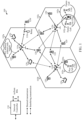
- FIG. 1 illustrates an example wireless network 100, such as a new radio (NR) or 5G network, in which aspects of the present disclosure may be performed.
- NR new radio
- 5G 5th Generation
- the wireless network 100 may include a number of base stations (BSs) 110 and other network entities.
- a BS may be a station that communicates with UEs.
- Each BS 110 may provide communication coverage for a particular geographic area.
- the term "cell” can refer to a coverage area of a Node B and/or a NB subsystem serving this coverage area, depending on the context in which the term is used.
- the term "cell” and evolved NB (eNB), NB, 5G NB, Next Generation NB (gNB), access point (AP), BS, NR BS, 5G BS, or transmission reception point (TRP) may be interchangeable.
- a cell may not necessarily be stationary, and the geographic area of the cell may move according to the location of a mobile BS.
- the BSs may be interconnected to one another and/or to one or more other BSs or network nodes (not shown) in the wireless network 100 through various types of backhaul interfaces such as a direct physical connection, a virtual network, or the like using any suitable transport network.
- any number of wireless networks may be deployed in a given geographic area.
- Each wireless network may support a particular radio access technology (RAT) and may operate on one or more frequencies.
- a RAT may also be referred to as a radio technology, an air interface, etc.
- a frequency may also be referred to as a carrier, a frequency channel, etc.
- Each frequency may support a single RAT in a given geographic area in order to avoid interference between wireless networks of different RATs.
- NR or 5G RAT networks may be deployed.
- a BS may provide communication coverage for a macro cell, a pico cell, a femto cell, and/or other types of cell.
- a macro cell may cover a relatively large geographic area (e.g., several kilometers in radius) and may allow unrestricted access by UEs with service subscription.
- a pico cell may cover a relatively small geographic area and may allow unrestricted access by UEs with service subscription.
- a femto cell may cover a relatively small geographic area (e.g., a home) and may allow restricted access by UEs having association with the femto cell (e.g., UEs in a Closed Subscriber Group (CSG), UEs for users in the home, etc.).
- CSG Closed Subscriber Group
- a BS for a macro cell may be referred to as a macro BS.
- a BS for a pico cell may be referred to as a pico BS.
- a BS for a femto cell may be referred to as a femto BS or a home BS.
- the BSs 110a, 110b and 110c may be macro BSs for the macro cells 102a, 102b and 102c, respectively.
- the BS 110x may be a pico BS for a pico cell 102x.
- the BSs 110y and 110z may be femto BS for the femto cells 102y and 102z, respectively.
- a BS may support one or multiple (e.g., three) cells.
- the wireless network 100 may also include relay stations.
- a relay station is a station that receives a transmission of data and/or other information from an upstream station (e.g., a BS or a UE) and sends a transmission of the data and/or other information to a downstream station (e.g., a UE or a BS).
- a relay station may also be a UE that relays transmissions for other UEs.
- a relay station 110r may communicate with the BS 110a and a UE 120r in order to facilitate communication between the BS 110a and the UE 120r.
- a relay station may also be referred to as a relay BS, a relay, etc.
- the wireless network 100 may be a heterogeneous network that includes BSs of different types, e.g., macro BS, pico BS, femto BS, relays, etc. These different types of BSs may have different transmit power levels, different coverage areas, and different impact on interference in the wireless network 100.
- macro BS may have a high transmit power level (e.g., 20 Watts) whereas pico BS, femto BS, and relays may have a lower transmit power level (e.g., 1 Watt).
- the wireless network 100 may support synchronous or asynchronous operation.
- the BSs may have similar frame timing, and transmissions from different BSs may be approximately aligned in time.
- the BSs may have different frame timing, and transmissions from different BSs may not be aligned in time.
- the techniques described herein may be used for both synchronous and asynchronous operation.
- a network controller 130 may be coupled to a set of BSs and provide coordination and control for these BSs.
- the network controller 130 may communicate with the BSs 110 via a backhaul.
- the BSs 110 may also communicate with one another, e.g., directly or indirectly via wireless or wireline backhaul.
- the UEs 120 may be dispersed throughout the wireless network 100, and each UE may be stationary or mobile.
- a UE may also be referred to as a mobile station, a terminal, an access terminal, a subscriber unit, a station, a Customer Premises Equipment (CPE), a cellular phone, a smart phone, a personal digital assistant (PDA), a wireless modem, a wireless communication device, a handheld device, a laptop computer, a cordless phone, a wireless local loop (WLL) station, a tablet, a camera, a gaming device, a netbook, a smartbook, an ultrabook, a medical device or medical equipment, a biometric sensor/device, a wearable device such as a smart watch, smart clothing, smart glasses, a smart wrist band, smart jewelry (e.g., a smart ring, a smart bracelet, etc.), an entertainment device (e.g., a music device, a video device, a
- CPE Customer Premises Equipment
- MTC and eMTC UEs include, for example, robots, drones, remote devices, sensors, meters, monitors, location tags, etc., that may communicate with a BS, another device (e.g., remote device), or some other entity.
- a wireless node may provide, for example, connectivity for or to a network (e.g., a wide area network such as Internet or a cellular network) via a wired or wireless communication link.
- Some UEs may be considered Internet-of Things (IoT) or narrowband IoT (NB-IoT) devices.
- IoT Internet-of Things
- NB-IoT narrowband IoT
- a solid line with double arrows indicates desired transmissions between a UE and a serving BS, which is a BS designated to serve the UE on the downlink and/or uplink.
- a dashed line with double arrows indicates interfering transmissions between a UE and a BS.
- Certain wireless networks utilize orthogonal frequency division multiplexing (OFDM) on the downlink and single-carrier frequency division multiplexing (SC-FDM) on the uplink.
- OFDM and SC-FDM partition the system bandwidth into multiple (K) orthogonal subcarriers, which are also commonly referred to as tones, bins, subbands, etc.
- K orthogonal subcarriers
- Each subcarrier may be modulated with data.
- modulation symbols are sent in the frequency domain with OFDM and in the time domain with SC-FDM.
- the spacing between adjacent subcarriers may be fixed, and the total number of subcarriers (K) may be dependent on the system bandwidth.
- the spacing of the subcarriers may be 15 kHz and the minimum resource allocation (called a resource block (RB)) may be 12 subcarriers (or 180 kHz). Consequently, the nominal FFT size may be equal to 128, 256, 512, 1024 or 2048 for system bandwidth of 1.25, 2.5, 5, 10 or 20 megahertz (MHz), respectively.
- the system bandwidth may also be partitioned into subbands. For example, a subband may cover 1.08 MHz (i.e., 6 RBs), and there may be 1, 2, 4, 8 or 16 subbands for system bandwidth of 1.25, 2.5, 5, 10 or 20 MHz, respectively.
- NR may utilize OFDM with a CP on the uplink and downlink and include support for half-duplex operation using time division duplex (TDD).
- TDD time division duplex
- a single component carrier bandwidth of 100 MHz may be supported.
- NR resource blocks may span 12 sub-carriers with a sub-carrier bandwidth of 75 kHz over a 0.1 ms duration.
- Each radio frame may consist of 50 subframes with a length of 10 ms. Consequently, each subframe may have a length of 0.2 ms.
- Each subframe may indicate a link direction (i.e., DL or UL) for data transmission and the link direction for each subframe may be dynamically switched.
- Each subframe may include DL/UL data as well as DL/UL control data.
- UL and DL subframes for NR may be as described in more detail below with respect to FIGs. 6 and 7 .
- Beamforming may be supported and beam direction may be dynamically configured.
- MIMO transmissions with precoding may also be supported.
- MIMO configurations in the DL may support up to 8 transmit antennas with multi-layer DL transmissions up to 8 streams and up to 2 streams per UE. Multi-layer transmissions with up to 2 streams per UE may be supported. Aggregation of multiple cells may be supported with up to 8 serving cells.
- NR may support a different air interface, other than an OFDM-based.
- NR networks may include entities such CUs and/or DUs.
- a scheduling entity e.g., a BS
- the scheduling entity may be responsible for scheduling, assigning, reconfiguring, and releasing resources for one or more subordinate entities. That is, for scheduled communication, subordinate entities utilize resources allocated by the scheduling entity.
- BSs are not the only entities that may function as a scheduling entity. That is, in some examples, a UE may function as a scheduling entity, scheduling resources for one or more subordinate entities (e.g., one or more other UEs).
- the UE is functioning as a scheduling entity, and other UEs utilize resources scheduled by the UE for wireless communication.
- a UE may function as a scheduling entity in a peer-to-peer (P2P) network, and/or in a mesh network.
- P2P peer-to-peer
- UEs may optionally communicate directly with one another in addition to communicating with the scheduling entity.
- a scheduling entity and one or more subordinate entities may communicate utilizing the scheduled resources.
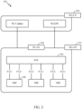
- FIG. 2 illustrates an example logical architecture of a distributed radio access network (RAN) 200, which may be implemented in the wireless communication system illustrated in FIG. 1 .
- a 5G access node 206 may include an access node controller (ANC) 202.
- the ANC 202 may be a central unit (CU) of the distributed RAN 200.
- the backhaul interface to the next generation core network (NG-CN) 204 may terminate at the ANC 202.
- the backhaul interface to neighboring next generation access nodes (NG-ANs) 210 may terminate at the ANC 202.
- the ANC 202 may include one or more TRPs 208. As described above, a TRP may be used interchangeably with "cell".
- the TRPs 208 may be a DU.
- the TRPs may be connected to one ANC (ANC 202) or more than one ANC (not illustrated).
- ANC 202 ANC 202
- ANC radio as a service
- a TRP 208 may include one or more antenna ports.
- the TRPs may be configured to individually (e.g., dynamic selection) or jointly (e.g., joint transmission) serve traffic to a UE.
- the logical architecture may support fronthauling solutions across different deployment types.
- the logical architecture may be based on transmit network capabilities (e.g., bandwidth, latency, and/or jitter).
- the logical architecture may share features and/or components with LTE.
- the NG-AN 210 may support dual connectivity with NR.
- the NG-AN 210 may share a common fronthaul for LTE and NR.
- the logical architecture may enable cooperation between and among TRPs 208. For example, cooperation may be preset within a TRP and/or across TRPs via the ANC 202. An inter-TRP interface may not be present.
- the logical architecture may have a dynamic configuration of split logical functions.
- the Radio Resource Control (RRC) layer may be adaptably placed at the DU or CU (e.g., TRP or ANC, respectively).
- RRC Radio Resource Control
- PDCP Packet Data Convergence Protocol
- RLC Radio Link Control
- MAC Medium Access Control
- PHY Physical
- a BS may include a central unit (CU) (e.g., ANC 202) and/or one or more distributed units (e.g., one or more TRPs 208).
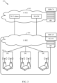
- FIG. 3 illustrates an example physical architecture of a distributed RAN 300, according to aspects of the present disclosure.
- a centralized core network unit (C-CU) 302 may host core network functions.
- the C-CU 302 may be centrally deployed.
- C-CU functionality may be offloaded (e.g., to advanced wireless services (AWS)), in an effort to handle peak capacity.
- a centralized RAN unit (C-RU) 304 may host one or more ANC functions.
- the C-RU 304 may host core network functions locally.
- the C-RU 304 may have distributed deployment.
- the C-RU 304 may be close to the network edge.
- a DU 306 may host one or more TRPs.
- the DU 306 may be located at edges of the network with radio frequency (RF) functionality.
- RF radio frequency
- FIG. 4 illustrates example components of the BS 110 and UE 120 illustrated in FIG. 1 , which may be used to implement aspects of the present disclosure.
- the BS may include a transmitter receiver point (TRP).
- TRP transmitter receiver point
- One or more components of the BS 110 and UE 120 may be used to practice aspects of the present disclosure.
- antennas 452, Tx/Rx 222, processors 466, 458, 464, and/or controller/processor 480 of the UE 120 and/or antennas 434, processors 460, 420, 438, and/or controller/processor 440 of the BS 110 may be used to perform the operations described herein and illustrated with reference to FIGs. 10 , 11 , 14, and 15.
- FIG. 4 shows a block diagram of a design of a BS 110 and a UE 120, which may be one of the BSs and one of the UEs in FIG. 1 .
- the BS 110 may be the macro BS 110c in FIG. 1
- the UE 120 may be the UE 120y.
- the BS 110 may also be a BS of some other type.
- the BS 110 may be equipped with antennas 434a through 434t, and the UE 120 may be equipped with antennas 452a through 452r.
- a transmit processor 420 may receive data from a data source 412 and control information from a controller/processor 440.
- the control information may be for the Physical Broadcast Channel (PBCH), Physical Control Format Indicator Channel (PCFICH), Physical Hybrid ARQ Indicator Channel (PHICH), Physical Downlink Control Channel (PDCCH), etc.
- the data may be for the Physical Downlink Shared Channel (PDSCH), etc.
- the processor 420 may process (e.g., encode and symbol map) the data and control information to obtain data symbols and control symbols, respectively.
- the processor 420 may also generate reference symbols, e.g., for the PSS, SSS, and cell-specific reference signal
- a transmit (TX) multiple-input multiple-output (MIMO) processor 430 may perform spatial processing (e.g., precoding) on the data symbols, the control symbols, and/or the reference symbols, if applicable, and may provide output symbol streams to the modulators (MODs) 432a through 432t.
- the TX MIMO processor 430 may perform certain aspects described herein for RS multiplexing.
- Each modulator 432 may process a respective output symbol stream (e.g., for OFDM, etc.) to obtain an output sample stream.
- Each modulator 432 may further process (e.g., convert to analog, amplify, filter, and upconvert) the output sample stream to obtain a downlink signal. Downlink signals from modulators 432a through 432t may be transmitted via the antennas 434a through 434t, respectively.
- the antennas 452a through 452r may receive the downlink signals from the base station 110 and may provide received signals to the demodulators (DEMODs) 454a through 454r, respectively.
- Each demodulator 454 may condition (e.g., filter, amplify, downconvert, and digitize) a respective received signal to obtain input samples.
- Each demodulator 454 may further process the input samples (e.g., for OFDM, etc.) to obtain received symbols.
- a MIMO detector 456 may obtain received symbols from all the demodulators 454a through 454r, perform MIMO detection on the received symbols if applicable, and provide detected symbols. For example, MIMO detector 456 may provide detected RS transmitted using techniques described herein.
- a receive processor 458 may process (e.g., demodulate, deinterleave, and decode) the detected symbols, provide decoded data for the UE 120 to a data sink 460, and provide decoded control information to a controller/processor 480.
- a transmit processor 464 may receive and process data (e.g., for the Physical Uplink Shared Channel (PUSCH)) from a data source 462 and control information (e.g., for the Physical Uplink Control Channel (PUCCH) from the controller/processor 480.
- the transmit processor 464 may also generate reference symbols for a reference signal.
- the symbols from the transmit processor 464 may be precoded by a TX MIMO processor 466 if applicable, further processed by the demodulators 454a through 454r (e.g., for SC-FDM, etc.), and transmitted to the BS 110.
- the uplink signals from the UE 120 may be received by the antennas 434, processed by the modulators 432, detected by a MIMO detector 436 if applicable, and further processed by a receive processor 438 to obtain decoded data and control information sent by the UE 120.
- the receive processor 438 may provide the decoded data to a data sink 439 and the decoded control information to the controller/processor 440.
- the controllers/processors 440 and 480 may direct the operation at the base station 110 and the UE 120, respectively.
- the processor 440 and/or other processors and modules at the base station 110 may perform or direct, e.g., the execution of the functional blocks illustrated in FIGs. 10 , 11 , 13, and 14 and/or other processes for the techniques described herein.
- the processor 480 and/or other processors and modules at the UE 120 may also perform or direct processes for the techniques described herein.
- the memories 442 and 482 may store data and program codes for the BS 110 and the UE 120, respectively.
- a scheduler 444 may schedule UEs for data transmission on the downlink and/or uplink.
- FIG. 5 illustrates a diagram 500 showing examples for implementing a communications protocol stack, according to aspects of the present disclosure.
- the illustrated communications protocol stacks may be implemented by devices operating in a in a 5G system (e.g., a system that supports uplink-based mobility).
- Diagram 500 illustrates a communications protocol stack including a Radio Resource Control (RRC) layer 510, a Packet Data Convergence Protocol (PDCP) layer 515, a Radio Link Control (RLC) layer 520, a Medium Access Control (MAC) layer 525, and a Physical (PHY) layer 530.
- RRC Radio Resource Control
- PDCP Packet Data Convergence Protocol
- RLC Radio Link Control
- MAC Medium Access Control
- PHY Physical
- the layers of a protocol stack may be implemented as separate modules of software, portions of a processor or ASIC, portions of non-collocated devices connected by a communications link, or various combinations thereof. Collocated and non-collocated implementations may be used, for example, in a protocol stack for a network access device (e.g., ANs, CUs, and/or DUs) or a UE.
- a network access device e.g., ANs, CUs, and/or DUs
- a first option 505-a shows a split implementation of a protocol stack, in which implementation of the protocol stack is split between a centralized network access device (e.g., an ANC 202 in FIG. 2 ) and distributed network access device (e.g., DU 208 in FIG. 2 ).
- a centralized network access device e.g., an ANC 202 in FIG. 2
- distributed network access device e.g., DU 208 in FIG. 2
- an RRC layer 510 and a PDCP layer 515 may be implemented by the central unit
- an RLC layer 520, a MAC layer 525, and a PHY layer 530 may be implemented by the DU.
- the CU and the DU may be collocated or non-collocated.
- the first option 505-a may be useful in a macro cell, micro cell, or pico cell deployment.
- a second option 505-b shows a unified implementation of a protocol stack, in which the protocol stack is implemented in a single network access device (e.g., access node (AN), new radio base station (NR BS), a new radio Node-B (NR NB), a network node (NN), or the like.).
- the RRC layer 510, the PDCP layer 515, the RLC layer 520, the MAC layer 525, and the PHY layer 530 may each be implemented by the AN.
- the second option 505-b may be useful in a femto cell deployment.
- a UE may implement an entire protocol stack (e.g., the RRC layer 510, the PDCP layer 515, the RLC layer 520, the MAC layer 525, and the PHY layer 530).
- an entire protocol stack e.g., the RRC layer 510, the PDCP layer 515, the RLC layer 520, the MAC layer 525, and the PHY layer 530.
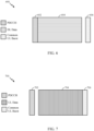
- FIG. 6 is a diagram showing an example of a DL-centric subframe 600 (e.g., also referred to as a slot).
- the DL-centric subframe 600 may include a control portion 602.
- the control portion 602 may exist in the initial or beginning portion of the DL-centric subframe.
- the control portion 602 may include various scheduling information and/or control information corresponding to various portions of the DL-centric subframe 600.
- the control portion 602 may be a physical DL control channel (PDCCH), as indicated in FIG. 6 .
- the DL-centric subframe 600 may also include a DL data portion 604.
- the DL data portion 604 may be referred to as the payload of the DL-centric subframe 600.
- the DL data portion 604 may include the communication resources utilized to communicate DL data from the scheduling entity (e.g., UE or BS) to the subordinate entity (e.g., UE).
- the DL data portion 604 may be a physical DL shared channel (PDSCH).
- PDSCH physical DL shared channel
- the DL-centric subframe 600 may also include a common UL portion 606.
- the common UL portion 606 may sometimes be referred to as an UL burst, a common UL burst, and/or various other suitable terms.
- the common UL portion 606 may include feedback information corresponding to various other portions of the DL-centric subframe 600.
- the common UL portion 606 may include feedback information corresponding to the control portion 602.
- Non-limiting examples of feedback information may include an ACK signal, a NACK signal, a HARQ indicator, and/or various other suitable types of information.
- the common UL portion 606 may include additional or alternative information, such as information pertaining to random access channel (RACH) procedures, scheduling requests (SRs), and various other suitable types of information.
- RACH random access channel
- SRs scheduling requests
- the end of the DL data portion 604 may be separated in time from the beginning of the common UL portion 606.
- This time separation may be referred to as a gap, a guard period, a guard interval, and/or various other suitable terms.
- This separation provides time for the switch-over from DL communication (e.g., reception operation by the subordinate entity (e.g., UE)) to UL communication (e.g., transmission by the subordinate entity (e.g., UE)).
- DL communication e.g., reception operation by the subordinate entity (e.g., UE)
- UL communication e.g., transmission by the subordinate entity (e.g., UE)
- FIG. 7 is a diagram showing an example of an UL-centric subframe 700.
- the UL-centric subframe 700 may include a control portion 702.
- the control portion 702 may exist in the initial or beginning portion of the UL-centric subframe 700.
- the control portion 702 in FIG. 7 may be similar to the control portion 602 described above with reference to FIG. 6 .
- the UL-centric subframe 700 may also include an UL data portion 704.
- the UL data portion 704 may be referred to as the payload of the UL-centric subframe.
- the UL portion may refer to the communication resources utilized to communicate UL data from the subordinate entity (e.g., UE) to the scheduling entity (e.g., UE or BS).
- the control portion 702 may be a PDCCH.
- the end of the control portion 702 may be separated in time from the beginning of the UL data portion 704. This time separation may be referred to as a gap, guard period, guard interval, and/or various other suitable terms. This separation provides time for the switch-over from DL communication (e.g., reception operation by the scheduling entity) to UL communication (e.g., transmission by the scheduling entity).
- the UL-centric subframe 700 may also include a common UL portion 706.
- the common UL portion 706 in FIG. 7 may be similar to the common UL portion 606 described above with reference to FIG. 6 .
- the common UL portion 706 may additional or alternative include information pertaining to channel quality indicator (CQI), sounding reference signals (SRSs), and various other suitable types of information.
- CQI channel quality indicator
- SRSs sounding reference signals
- One of ordinary skill in the art will understand that the foregoing is merely one example of an UL-centric subframe and alternative structures having similar features may exist without necessarily deviating from the aspects described herein.
- two or more subordinate entities may communicate with each other using sidelink signals.
- Real-world applications of such sidelink communications may include public safety, proximity services, UE-to-network relaying, vehicle-to-vehicle (V2V) communications, Internet of Everything (IoE) communications, IoT communications, mission-critical mesh, and/or various other suitable applications.
- a sidelink signal may refer to a signal communicated from one subordinate entity (e.g., UE1) to another subordinate entity (e.g., UE2) without relaying that communication through the scheduling entity (e.g., UE or BS), even though the scheduling entity may be utilized for scheduling and/or control purposes.
- the sidelink signals may be communicated using a licensed spectrum (unlike wireless local area networks, which typically use an unlicensed spectrum).
- a coreset may include one or more control resources (e.g., time and frequency resources) configured for conveying the control information.
- one or more search spaces e.g., common search space, UE-specific search space, etc.
- search space generally refers to the set of resources on which different decoding candidates for a channel of a defined format, such as a PDCCH, may be transmitted.
- Each decoding candidate refers to resources for one valid channel transmission. The number of valid decoding candidates depends on the size of the search space and the size (payload) of each channel.
- a coreset may be defined in units of resource element groups (REGs).
- Each REG may include a fixed number (e.g., twelve, or some other number) of tones in one symbol period (e.g., a symbol period of a slot), where one tone in one symbol period is referred to as a resource element (RE).
- a fixed number of REGs may be included in a control channel element (CCE) (e.g., a CCE may include six REGs).
- CCE control channel element
- Sets of CCEs may be used to transmit NR-PDCCH, with different numbers of CCEs in the sets used to transmit NR-PDCCH using differing aggregation levels.
- Multiple sets of CCEs may be defined as search spaces for UEs, and thus a NodeB or other base station may transmit an NR-PDCCH to a UE by transmitting the NR-PDCCH in a set of CCEs that is defined as a decoding candidate within a search space for the UE, and the UE may receive the NR-PDCCH by searching in search spaces for the UE and decoding the NR-PDCCH transmitted by the NodeB.
- a next generation Node B (e.g., gNB) (e.g., in communication systems that support NR) may support coresets of different lengths that span multiple symbol periods (e.g., OFDM symbol periods). That is, the control channel candidates may be mapped to a single OFDM or multiple (e.g., two, three, etc.) OFDM symbols. Coresets can be associated with different aggregation levels.
- Certain wireless communication system deployments utilize multiple downlink (DL) component carriers (CCs) as part of a carrier aggregation (CA) scheme.
- DL downlink
- CCs component carriers
- CA carrier aggregation
- Supplemental DL may generally refer to a DL CC without a corresponding UL CC in the cell.
- SDL may generally refer to the case when there is only DL resource for a carrier from the perspective of a device.
- Supplemental UL may generally refer to an UL CC without a corresponding DL CC in the cell.
- SUL may generally refer to the case when there is only UL resource for a carrier from the perspective of an NR device.
- aspects of the present disclosure provide techniques that may help support and enable RACH procedures in systems that allow a RACH transmission on either a (primary) UL CC or an SUL CC.
- SUL CCs may be used as a complimentary access link for NR TDD and NR frequency division duplex (FDD) scenarios.
- a UE may select PRACH resources either in the NR TDD/FDD uplink frequency or the SUL frequency.
- the SUL frequency can be a frequency shared with LTE UL (e.g., at least for the case when NR spectrum is below 6 Ghz).
- UE initial access may be based on a RACH configuration for an SUL carrier.
- the RACH configuration for the SUL carrier may be broadcast, for example, in remaining minimum system information (RMSI).
- RMSI remaining minimum system information
- the configuration information for the SUL carrier may be sufficient for UEs to complete RACH procedure via only that SUL carrier (e.g., the configuration information may include all necessary power control parameters).
- the configuration information for the SUL carrier may also include a threshold.
- the UE may be configured to select that SUL carrier for initial access if (and maybe only if) the reference signal receive power (RSRP) measured by the UE on the DL carrier where the UE receives RMSI is lower than the threshold.
- RSRP reference signal receive power
- the RACH procedure may be completed with all uplink transmissions (e.g., Msg1, Msg3) taking place on that carrier.
- the network may be able to request a connected-mode UE to initiate a RACH procedure towards any uplink carrier for path-loss and timing-advance acquisition.
- Allowing the RACH procedure on SUL may present various challenges. For example, if the SUL is paired with a NR TDD/FDD carrier, and the PRACH resources are available on a SUL carrier and a TDD/FDD carrier, allowing the RACH procedure on SUL will increase the collision probability during RA procedure.
- UE1 and UE2 This may be illustrated by considering an example with two UEs: UE1 and UE2. If UE1 selects SUL and UE2 selects the NR TDD/FDD carrier for PRACH transmission. If the two UEs select frequency resources for PRACH with the same frequency resource index, even though no collision happened during the Msgl transmission, the two UEs may detect the same PDCCH and associated Msg2, random access response (RAR) with the same random access radio network temporary identifier (RA-RNTI) if the LTE scheme of RA-RNTI determination is applied.
- RAR random access response
- RA-RNTI random access radio network temporary identifier
- RA random access
- the UE will monitor for the PDCCH identified by the RA-RNTI in the RA Response window after the transmission of the PRACH preamble, so as to detect the Msg2 (RAR).
- RAR Msg2
- aspects of the present disclosure may help accommodate the use of SUL for RACH procedures, by having the search space for the RACH response (RAR) be dependent, at least in part, on the UL CC used for the RACH transmission (e.g., based on the corresponding carrier index).
- RAR RACH response
- FIG. 9 illustrates example operations 900 for wireless communications by a UE, in accordance with aspects of the present disclosure. Operations 900 may be performed, for example, by UE 120 shown in FIG. 1 .
- Operations 900 begin, at 902, by transmitting a random access channel (RACH) on an uplink carrier selected from at least two available uplink carriers.
- RACH random access channel
- the UE determines, based on the uplink carrier on which the RACH was transmitted, a search space to monitor for a random access channel response (RAR) transmitted on a downlink carrier.
- RAR random access channel response
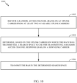
- FIG. 10 illustrates example operations 1000 for wireless communications, in accordance with aspects of the present disclosure.
- Operations 1000 may be performed by a base station (e.g., a gNB), such as BS 110 shown in FIG. 1 , performing initial access with a UE performing SUL based RACH operations 900 described above.
- a base station e.g., a gNB
- BS 110 shown in FIG. 1
- SUL based RACH operations 900 described above.
- Operations 1000 begin, at 1002, by receiving a random access channel (RACH) on an uplink carrier from at least two available uplink carriers.
- RACH random access channel
- the gNB determines, based on the uplink carrier on which the RACH was transmitted, a search space to use for transmitting a random access channel response (RAR) on a downlink carrier.
- RAR random access channel response
- the gNB transmits the RAR in the determined search space.
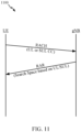
- FIG. 11 illustrates how the search space for the RAR depends on the UL CC selected for the RACH transmission.
- a first UL e.g., a NR TDD/FDD carrier
- a first search space is determined and (decoding candidates of that first search space) is monitored for RAR.
- a control resource set includes multiple search spaces.
- one of the multiple search spaces for the RAR transmission are assigned based on the carrier selected for the RACH transmission (e.g., based on the carrier index of the selected carrier).
- the separate coresets there are separate coresets defined and one of the separate coresets used for the RAR transmission are dependent on the carrier selected for the RACH transmission (e.g., based on the carrier index of the selected carrier).
- the search spaces corresponding to the different carriers will also be different.
- RA-RNTI may also be based on the selected UL carrier. In some cases, if the two carriers have different numerologies, RA-RNTI may also be based on the numerology, which may help further distinguish RAR transmissions.
- numerology generally refers to a set of parameters used for transmission in a carrier, such as tone spacing, and/or cyclic prefix lengths.
- a search space may also be determined based on the numerology. In such cases, based on a numerology for the uplink carrier on which the RACH was transmitted, a search space may be selected from at least two different search spaces within a same coreset.
- the methods disclosed herein comprise one or more steps or actions for achieving the described method.
- the method steps and/or actions may be interchanged with one another without departing from the scope of the claims.
- the order and/or use of specific steps and/or actions may be modified without departing from the scope of the claims.
- a phrase referring to "at least one of" a list of items refers to any combination of those items, including single members.
- "at least one of: a, b, or c” is intended to cover a, b, c, a-b, a-c, b-c, and a-b-c, as well as any combination with multiples of the same element (e.g., a-a, a-a-a, a-a-b, a-a-c, a-b-b, a-c-c, b-b, b-b-b, b-b-c, c-c, and c-c-c or any other ordering of a, b, and c).
- determining encompasses a wide variety of actions. For example, “determining” may include calculating, computing, processing, deriving, investigating, looking up (e.g., looking up in a table, a database or another data structure), ascertaining and the like. Also, “determining” may include receiving (e.g., receiving information), accessing (e.g., accessing data in a memory) and the like. Also, “determining” may include resolving, selecting, choosing, establishing and the like.
- the various operations of methods described above may be performed by any suitable means capable of performing the corresponding functions.
- the means may include various hardware and/or software component(s) and/or module(s), including, but not limited to a circuit, an application specific integrated circuit (ASIC), or processor.
- ASIC application specific integrated circuit
- means for transmitting and/or means for receiving may comprise one or more of a transmit processor 420, a TX MIMO processor 430, a receive processor 438, or antenna(s) 434 of the base station 110 and/or the transmit processor 464, a TX MIMO processor 466, a receive processor 458, or antenna(s) 452 of the user equipment 120.
- means for generating, means for multiplexing, and/or means for applying may comprise one or more processors, such as the controller/processor 440 of the base station 110 and/or the controller/processor 480 of the user equipment 120.
- DSP digital signal processor
- ASIC application specific integrated circuit
- FPGA field programmable gate array
- PLD programmable logic device
- a general-purpose processor may be a microprocessor, but in the alternative, the processor may be any commercially available processor, controller, microcontroller, or state machine.
- a processor may also be implemented as a combination of computing devices, e.g., a combination of a DSP and a microprocessor, a plurality of microprocessors, one or more microprocessors in conjunction with a DSP core, or any other such configuration.
- an example hardware configuration may comprise a processing system in a wireless node.
- the processing system may be implemented with a bus architecture.
- the bus may include any number of interconnecting buses and bridges depending on the specific application of the processing system and the overall design constraints.
- the bus may link together various circuits including a processor, machine-readable media, and a bus interface.
- the bus interface may be used to connect a network adapter, among other things, to the processing system via the bus.
- the network adapter may be used to implement the signal processing functions of the PHY layer.
- a user interface e.g., keypad, display, mouse, joystick, etc.
- the bus may also link various other circuits such as timing sources, peripherals, voltage regulators, power management circuits, and the like, which are well known in the art, and therefore, will not be described any further.
- the processor may be implemented with one or more general-purpose and/or special-purpose processors. Examples include microprocessors, microcontrollers, DSP processors, and other circuitry that can execute software. Those skilled in the art will recognize how best to implement the described functionality for the processing system depending on the particular application and the overall design constraints imposed on the overall system.
- the functions may be stored or transmitted over as one or more instructions or code on a computer readable medium.
- Software shall be construed broadly to mean instructions, data, or any combination thereof, whether referred to as software, firmware, middleware, microcode, hardware description language, or otherwise.
- Computer-readable media include both computer storage media and communication media including any medium that facilitates transfer of a computer program from one place to another.
- the processor may be responsible for managing the bus and general processing, including the execution of software modules stored on the machine-readable storage media.
- a computer-readable storage medium may be coupled to a processor such that the processor can read information from, and write information to, the storage medium. In the alternative, the storage medium may be integral to the processor.
- the machine-readable media may include a transmission line, a carrier wave modulated by data, and/or a computer readable storage medium with instructions stored thereon separate from the wireless node, all of which may be accessed by the processor through the bus interface.
- the machine-readable media, or any portion thereof may be integrated into the processor, such as the case may be with cache and/or general register files.
- machine-readable storage media may include, by way of example, RAM (Random Access Memory), flash memory, ROM (Read Only Memory), PROM (Programmable Read-Only Memory), EPROM (Erasable Programmable Read-Only Memory), EEPROM (Electrically Erasable Programmable Read-Only Memory), registers, magnetic disks, optical disks, hard drives, or any other suitable storage medium, or any combination thereof.
- RAM Random Access Memory
- ROM Read Only Memory
- PROM PROM
- EPROM Erasable Programmable Read-Only Memory
- EEPROM Electrical Erasable Programmable Read-Only Memory
- registers magnetic disks, optical disks, hard drives, or any other suitable storage medium, or any combination thereof.
- the machine-readable media may be embodied in a computer-program product.
- a software module may comprise a single instruction, or many instructions, and may be distributed over several different code segments, among different programs, and across multiple storage media.
- the computer-readable media may comprise a number of software modules.
- the software modules include instructions that, when executed by an apparatus such as a processor, cause the processing system to perform various functions.
- the software modules may include a transmission module and a receiving module. Each software module may reside in a single storage device or be distributed across multiple storage devices.
- a software module may be loaded into RAM from a hard drive when a triggering event occurs.
- the processor may load some of the instructions into cache to increase access speed.
- One or more cache lines may then be loaded into a general register file for execution by the processor.
- any connection is properly termed a computer-readable medium.
- the software is transmitted from a website, server, or other remote source using a coaxial cable, fiber optic cable, twisted pair, digital subscriber line (DSL), or wireless technologies such as infrared (IR), radio, and microwave
- the coaxial cable, fiber optic cable, twisted pair, DSL, or wireless technologies such as infrared, radio, and microwave are included in the definition of medium.
- Disk and disc include compact disc (CD), laser disc, optical disc, digital versatile disc (DVD), floppy disk, and Blu-ray ® disc where disks usually reproduce data magnetically, while discs reproduce data optically with lasers.
- computer-readable media may comprise non-transitory computer-readable media (e.g., tangible media).
- computer-readable media may comprise transitory computer-readable media (e.g., a signal). Combinations of the above should also be included within the scope of computer-readable media.
- certain aspects may comprise a computer program product for performing the operations presented herein.
- a computer program product may comprise a computer-readable medium having instructions stored (and/or encoded) thereon, the instructions being executable by one or more processors to perform the operations described herein.
- instructions for perform the operations described herein and illustrated in FIGs. 9 and 10 may be executable by one or more processors to perform the operations described herein.
- modules and/or other appropriate means for performing the methods and techniques described herein can be downloaded and/or otherwise obtained by a user terminal and/or base station as applicable.
- a user terminal and/or base station can be coupled to a server to facilitate the transfer of means for performing the methods described herein.
- various methods described herein can be provided via storage means (e.g., RAM, ROM, a physical storage medium such as a compact disc (CD) or floppy disk, etc.), such that a user terminal and/or base station can obtain the various methods upon coupling or providing the storage means to the device.
- storage means e.g., RAM, ROM, a physical storage medium such as a compact disc (CD) or floppy disk, etc.
- CD compact disc
- floppy disk etc.
- any other suitable technique for providing the methods and techniques described herein to a device can be utilized.
Landscapes
- Engineering & Computer Science (AREA)
- Signal Processing (AREA)
- Computer Networks & Wireless Communication (AREA)
- Mobile Radio Communication Systems (AREA)
Claims (9)
- Un procédé de communication sans fil par un équipement utilisateur, UE, comprenant :la transmission (902) d'une transmission de canal à accès aléatoire, RACH, sur une porteuse de liaison montante sélectionnée parmi au moins deux porteuses de liaison montante disponibles comportant une première porteuse de liaison montante, UL, et une porteuse de liaison montante supplémentaire, SUL ;la détermination (904), sur la base de la porteuse de liaison montante sur laquelle la transmission RACH a été transmise, d'un espace de recherche pour surveiller une réponse de canal à accès aléatoire, RAR, transmise sur une porteuse de liaison descendante, comprenant :la détermination, sur la base de la porteuse de liaison montante sur laquelle la transmission RACH a été transmise, d'un ensemble de ressources de contrôle, coreset, qui comporte des ressources de temps et de fréquence configurées pour transporter des informations de contrôle ; etla sélection, sur la base de la porteuse de liaison montante sur laquelle la transmission RACH a été transmise, de l'espace de recherche parmi de multiples espaces de recherche à l'intérieur du coreset déterminé, l'espace de recherche sélectionné étant pour la transmission RAR ;la détermination d'un identifiant temporaire de réseau radio à accès aléatoire, RA-RNTI, sur la base de la porteuse de liaison montante sur laquelle la transmission RACH a été transmise ; etla surveillance (906) de la RAR dans l'espace de recherche sélectionné en utilisant le RA-RNTI déterminé.
- Le procédé selon la revendication 1, dans lequel :les au moins deux porteuses de liaison montante disponibles ont des numérologies différentes ; etle RA-RNTI est déterminé également sur la base de la numérologie de la porteuse de liaison montante sur laquelle la transmission RACH a été transmise.
- Un procédé de communication sans fil par une entité de réseau, comprenant :la réception (1002) d'une transmission de canal à accès aléatoire, RACH, sur une porteuse de liaison montante parmi au moins deux porteuses de liaison montante disponibles comportant une première porteuse de liaison montante, UL, et une porteuse de liaison montante supplémentaire, SUL ;la détermination (1004), sur la base de la porteuse de liaison montante sur laquelle la transmission RACH a été transmise, d'un espace de recherche à utiliser pour la transmission d'une réponse de canal à accès aléatoire, RAR, sur une porteuse de liaison descendante, comprenant :la détermination, sur la base de la porteuse de liaison montante sur laquelle la transmission RACH a été transmise, d'un ensemble de ressources de contrôle, coreset, qui comporte des ressources de temps et de fréquence configurées pour transporter des informations de contrôle ; etla sélection, sur la base de la porteuse de liaison montante sur laquelle la transmission RACH a été transmise, de l'espace de recherche parmi de multiples espaces de recherche à l'intérieur du coreset déterminé, l'espace de recherche étant pour la transmission RAR ;la détermination d'un identifiant temporaire de réseau radio à accès aléatoire, RA-RNTI, sur la base de la porteuse de liaison montante sur laquelle la transmission RACH a été transmise ; etla transmission (1006) de la RAR dans l'espace de recherche sélectionné en utilisant le RA-RNTI déterminé pour transmettre la RAR.
- Le procédé selon la revendication 3, dans lequel :les au moins deux porteuses de liaison montante disponibles ont des numérologies différentes ; etle RA-RNTI est déterminé également sur la base de la numérologie de la porteuse de liaison montante sur laquelle la transmission RACH a été transmise.
- Un appareil pour la communication sans fil par un équipement utilisateur (120), UE, comprenant :un moyen pour transmettre une transmission de canal à accès aléatoire, RACH, sur une porteuse de liaison montante sélectionnée parmi au moins deux porteuses de liaison montante disponibles comportant une première porteuse de liaison montante, UL, etune porteuse de liaison montante supplémentaire, SUL ;un moyen pour déterminer, sur la base de la porteuse de liaison montante sur laquelle la transmission RACH a été transmise, un espace de recherche pour surveiller une réponse de canal à accès aléatoire, RAR, transmise sur une porteuse de liaison descendante, comprenant :un moyen pour déterminer, sur la base de la porteuse de liaison montante sur laquelle la transmission RACH a été transmise, un ensemble de ressources de contrôle, coreset, qui comporte des ressources de temps et de fréquence configurées pour transporter des informations de contrôle ; etun moyen pour sélectionner, sur la base de la porteuse de liaison montante sur laquelle la transmission RACH a été transmise, l'espace de recherche parmi de multiples espaces de recherche à l'intérieur du coreset déterminé, l'espace de recherche sélectionné étant pour la transmission RAR ;un moyen pour déterminer un identifiant temporaire de réseau radio à accès aléatoire, RA-RNTI, sur la base de la porteuse de liaison montante sur laquelle la transmission RACH a été transmise ;un moyen pour surveiller la RAR dans l'espace de recherche sélectionné ; etun moyen pour utiliser le RA-RNTI déterminé pour surveiller la RAR.
- L'appareil selon la revendication 5, dans lequel :les au moins deux porteuses de liaison montante disponibles ont des numérologies différentes ; etle RA-RNTI est déterminé également sur la base de la numérologie de la porteuse de liaison montante sur laquelle la transmission RACH a été transmise.
- Un appareil pour la communication sans fil par une entité de réseau (110), comprenant :un moyen pour recevoir une transmission de canal à accès aléatoire, RACH, sur une porteuse de liaison montante parmi au moins deux porteuses de liaison montante disponibles comportant une première porteuse de liaison montante, UL, et une porteuse de liaison montante supplémentaire, SUL ;un moyen pour déterminer, sur la base de la porteuse de liaison montante sur laquelle la transmission RACH a été transmise, un espace de recherche à utiliser pour la transmission d'une réponse de canal à accès aléatoire, RAR, sur une porteuse de liaison descendante, comprenant :un moyen pour déterminer, sur la base d'un indice de porteuse pour la porteuse de liaison montante sur laquelle la transmission RACH a été transmise, un ensemble de ressources de contrôle, coreset, qui comporte des ressources de temps et de fréquence configurées pour transporter des informations de contrôle ; etun moyen pour sélectionner, sur la base de la porteuse de liaison montante sur laquelle la transmission RACH a été transmise, l'espace de recherche parmi de multiples espaces de recherche à l'intérieur du coreset déterminé, l'espace de recherche sélectionné étant pour la transmission RAR ;un moyen pour déterminer un identifiant temporaire de réseau radio à accès aléatoire, RA-RNTI, sur la base de la porteuse de liaison montante sur laquelle la transmission RACH a été transmise ;un moyen pour transmettre la RAR dans l'espace de recherche sélectionné ; etun moyen pour utiliser le RA-RNTI déterminé pour transmettre la RAR.
- L'appareil selon la revendication 7, dans lequel :les au moins deux porteuses de liaison montante disponibles ont des numérologies différentes ; etle RA-RNTI est déterminé également sur la base de la numérologie de la porteuse de liaison montante sur laquelle la transmission RACH a été transmise.
- Un programme de calculateur comprenant des instructions qui, quand le programme est exécuté par un ou plusieurs processeurs, amènent les un ou plusieurs processeurs à réaliser le procédé selon les revendications 1 à 2 ou 3 à 4.
Applications Claiming Priority (3)
| Application Number | Priority Date | Filing Date | Title |
|---|---|---|---|
| US201762570050P | 2017-10-09 | 2017-10-09 | |
| US16/151,405 US11044757B2 (en) | 2017-10-09 | 2018-10-04 | Carrier-dependent random access channel (RACH) response search space |
| PCT/US2018/054532 WO2019074780A1 (fr) | 2017-10-09 | 2018-10-05 | Espace de recherche de réponse de canal d'accès aléatoire (rach) dépendant d'une porteuse |
Publications (2)
| Publication Number | Publication Date |
|---|---|
| EP3695681A1 EP3695681A1 (fr) | 2020-08-19 |
| EP3695681B1 true EP3695681B1 (fr) | 2023-08-16 |
Family
ID=65993598
Family Applications (1)
| Application Number | Title | Priority Date | Filing Date |
|---|---|---|---|
| EP18792808.0A Active EP3695681B1 (fr) | 2017-10-09 | 2018-10-05 | Espace de recherche de réponse de canal d'accès aléatoire (rach) dépendant d'une porteuse |
Country Status (9)
| Country | Link |
|---|---|
| US (1) | US11044757B2 (fr) |
| EP (1) | EP3695681B1 (fr) |
| JP (1) | JP7280873B2 (fr) |
| KR (1) | KR102690111B1 (fr) |
| CN (1) | CN111165064B (fr) |
| BR (1) | BR112020006864A2 (fr) |
| CA (1) | CA3074605A1 (fr) |
| TW (1) | TWI775962B (fr) |
| WO (1) | WO2019074780A1 (fr) |
Families Citing this family (4)
| Publication number | Priority date | Publication date | Assignee | Title |
|---|---|---|---|---|
| CN112087810B (zh) * | 2019-06-14 | 2023-01-06 | 华为技术有限公司 | 一种随机接入方法及装置 |
| CN115734382A (zh) * | 2019-09-26 | 2023-03-03 | 苹果公司 | 用于无线通信中的两步随机接入信道过程的框架 |
| US20230106898A1 (en) * | 2020-03-09 | 2023-04-06 | Beijing Xiaomi Mobile Software Co., Ltd. | Communication method and apparatus, and storage medium |
| KR102423068B1 (ko) * | 2021-09-07 | 2022-07-20 | 주식회사 블랙핀 | 무선 이동 통신 시스템에서 축소된 성능의 단말이 복수의 탐색구간과 제어자원셋을 이용해서 랜덤 액세스를 수행하는 방법 및 장치 |
Family Cites Families (14)
| Publication number | Priority date | Publication date | Assignee | Title |
|---|---|---|---|---|
| NO304400B1 (no) | 1992-03-30 | 1998-12-07 | Sediver Sociutu Europ D Isolat | Anordning for Õ pÕvise og anvise en feilstr°m gjennom en lynavleder eller en isolator |
| CN2414537Y (zh) | 1999-08-06 | 2001-01-10 | 姚巧玲 | 高压避雷器脱离和故障指示器 |
| ES2905362T3 (es) * | 2009-04-23 | 2022-04-08 | Interdigital Patent Holdings Inc | Método y aparato para acceso aleatorio en comunicaciones inalámbricas multiportadoras |
| US8426736B2 (en) | 2009-07-17 | 2013-04-23 | The Invention Science Fund I Llc | Maintaining insulators in power transmission systems |
| JP5435139B2 (ja) * | 2010-08-13 | 2014-03-05 | 富士通株式会社 | 無線通信システム、基地局、中継局および無線通信方法 |
| US9467959B2 (en) * | 2011-04-01 | 2016-10-11 | Mediatek, Inc. | Method of maintaining multiple timing advance |
| WO2013006111A1 (fr) * | 2011-07-06 | 2013-01-10 | Telefonaktiebolaget L M Ericsson (Publ) | Accès aléatoire utilisant des communications par porteuses élémentaires primaire et secondaire |
| US10079658B2 (en) * | 2011-11-04 | 2018-09-18 | Qualcomm Incorporated | Search space design for e-PDCCH in wireless communication networks |
| US9814073B2 (en) * | 2013-01-30 | 2017-11-07 | Qualcomm Incorporated | PRACH-based proximity detection |
| CN105992385B (zh) * | 2015-02-12 | 2019-12-31 | 苏州简约纳电子有限公司 | 物理随机接入信道信号生成方法 |
| WO2018054305A1 (fr) * | 2016-09-20 | 2018-03-29 | Mediatek Inc. | Procédé et appareil de transmission de données avec de multiples porteuses de liaison montante dans des communications mobiles |
| EP3603300B1 (fr) * | 2017-03-24 | 2024-07-03 | Motorola Mobility LLC | Procédé et appareil d'accès aléatoire à un réseau de communication sans fil |
| CN111066353A (zh) * | 2017-09-08 | 2020-04-24 | Oppo广东移动通信有限公司 | 无线通信方法、网络设备和终端设备 |
| US11291041B2 (en) * | 2018-04-05 | 2022-03-29 | Mediatek Inc. | Simultaneous uplink transmissions |
-
2018
- 2018-10-04 US US16/151,405 patent/US11044757B2/en active Active
- 2018-10-05 TW TW107135220A patent/TWI775962B/zh active
- 2018-10-05 JP JP2020519978A patent/JP7280873B2/ja active Active
- 2018-10-05 KR KR1020207009650A patent/KR102690111B1/ko active IP Right Grant
- 2018-10-05 WO PCT/US2018/054532 patent/WO2019074780A1/fr unknown
- 2018-10-05 CA CA3074605A patent/CA3074605A1/fr active Pending
- 2018-10-05 BR BR112020006864-0A patent/BR112020006864A2/pt unknown
- 2018-10-05 EP EP18792808.0A patent/EP3695681B1/fr active Active
- 2018-10-05 CN CN201880064376.5A patent/CN111165064B/zh active Active
Also Published As
| Publication number | Publication date |
|---|---|
| BR112020006864A2 (pt) | 2020-10-06 |
| WO2019074780A1 (fr) | 2019-04-18 |
| JP2020537407A (ja) | 2020-12-17 |
| US20190110320A1 (en) | 2019-04-11 |
| CN111165064B (zh) | 2023-11-28 |
| KR20200061353A (ko) | 2020-06-02 |
| JP7280873B2 (ja) | 2023-05-24 |
| CN111165064A (zh) | 2020-05-15 |
| US11044757B2 (en) | 2021-06-22 |
| TWI775962B (zh) | 2022-09-01 |
| EP3695681A1 (fr) | 2020-08-19 |
| CA3074605A1 (fr) | 2019-04-18 |
| TW201924457A (zh) | 2019-06-16 |
| KR102690111B1 (ko) | 2024-07-30 |
Similar Documents
| Publication | Publication Date | Title |
|---|---|---|
| EP3701746B1 (fr) | Techniques de transmission et de surveillance de pdcch rmsi | |
| EP3529937B1 (fr) | Surveillance d'espace de recherche de commande basée sur un type de service | |
| EP3619962B1 (fr) | Configuration de fenêtre restante de transmission d'informations système | |
| EP3673605B1 (fr) | Multiplexage de signaux de référence d'informations d'état de canal et de signaux de synchronisation dans une nouvelle technologie radioélectrique | |
| EP3527034B1 (fr) | Signal de réservation de canal multiétage servant à une émission et à une réception directionnelles | |
| US11381365B2 (en) | Collision of sounding reference signal (SRS) and physical uplink shared channel (PUSCH) in case of carrier aggregation | |
| EP3704826B1 (fr) | Désambiguïsation de réponse d'accès aléatoire pour un support d'accès aléatoire sur une liaison montante supplémentaire | |
| EP3704908A1 (fr) | Granularité d'avance de temporisation pour liaison montante ayant différentes numérologies | |
| AU2019211145B2 (en) | Uplink power control configuration | |
| EP3580963B1 (fr) | Gestion d'indexation temporelle dans une coexistence lte-nr | |
| WO2020056726A1 (fr) | Multiplexage d'informations de commande de liaison montante sur un canal de commande de liaison montante physique | |
| EP3711422B1 (fr) | Planification efficace de données avec porteuse de liaison montante supplémentaire | |
| WO2019192007A1 (fr) | Traitement de collision destiné au rapport de csi sur pusch | |
| EP3804203B1 (fr) | Multiplexage spatial d'un canal de commande de liaison montante physique (pucch) et d'un signal de référence de sondage (srs) | |
| EP3695681B1 (fr) | Espace de recherche de réponse de canal d'accès aléatoire (rach) dépendant d'une porteuse | |
| WO2018191646A1 (fr) | Multiplexage de demande de planification basé sur des objectifs de fiabilité et de latence | |
| WO2019018232A1 (fr) | Combinaison d'informations à travers des faisceaux | |
| EP4369836A2 (fr) | Indicateur de réduction spécifique de liaison montante | |
| EP3704904A1 (fr) | Compte-rendu de marge de puissance d'intervalle de temps de transmission (tti) court | |
| EP3542501B1 (fr) | Entrelacement en peigne de signaux de données et de signaux de référence à étalement de spectre par dft | |
| WO2020118568A1 (fr) | Sélection de réseau basée sur des informations de capteur |
Legal Events
| Date | Code | Title | Description |
|---|---|---|---|
| STAA | Information on the status of an ep patent application or granted ep patent |
Free format text: STATUS: UNKNOWN |
|
| STAA | Information on the status of an ep patent application or granted ep patent |
Free format text: STATUS: THE INTERNATIONAL PUBLICATION HAS BEEN MADE |
|
| PUAI | Public reference made under article 153(3) epc to a published international application that has entered the european phase |
Free format text: ORIGINAL CODE: 0009012 |
|
| STAA | Information on the status of an ep patent application or granted ep patent |
Free format text: STATUS: REQUEST FOR EXAMINATION WAS MADE |
|
| 17P | Request for examination filed |
Effective date: 20200227 |
|
| AK | Designated contracting states |
Kind code of ref document: A1 Designated state(s): AL AT BE BG CH CY CZ DE DK EE ES FI FR GB GR HR HU IE IS IT LI LT LU LV MC MK MT NL NO PL PT RO RS SE SI SK SM TR |
|
| AX | Request for extension of the european patent |
Extension state: BA ME |
|
| DAV | Request for validation of the european patent (deleted) | ||
| DAX | Request for extension of the european patent (deleted) | ||
| STAA | Information on the status of an ep patent application or granted ep patent |
Free format text: STATUS: EXAMINATION IS IN PROGRESS |
|
| 17Q | First examination report despatched |
Effective date: 20211001 |
|
| REG | Reference to a national code |
Ref document number: 602018055541 Country of ref document: DE Ref country code: DE Ref legal event code: R079 Free format text: PREVIOUS MAIN CLASS: H04W0074080000 Ipc: H04L0005000000 |
|
| GRAP | Despatch of communication of intention to grant a patent |
Free format text: ORIGINAL CODE: EPIDOSNIGR1 |
|
| STAA | Information on the status of an ep patent application or granted ep patent |
Free format text: STATUS: GRANT OF PATENT IS INTENDED |
|
| RIC1 | Information provided on ipc code assigned before grant |
Ipc: H04W 74/00 20090101ALN20230215BHEP Ipc: H04W 74/08 20090101ALI20230215BHEP Ipc: H04L 5/00 20060101AFI20230215BHEP |
|
| INTG | Intention to grant announced |
Effective date: 20230306 |
|
| GRAS | Grant fee paid |
Free format text: ORIGINAL CODE: EPIDOSNIGR3 |
|
| GRAA | (expected) grant |
Free format text: ORIGINAL CODE: 0009210 |
|
| STAA | Information on the status of an ep patent application or granted ep patent |
Free format text: STATUS: THE PATENT HAS BEEN GRANTED |
|
| AK | Designated contracting states |
Kind code of ref document: B1 Designated state(s): AL AT BE BG CH CY CZ DE DK EE ES FI FR GB GR HR HU IE IS IT LI LT LU LV MC MK MT NL NO PL PT RO RS SE SI SK SM TR |
|
| REG | Reference to a national code |
Ref country code: CH Ref legal event code: EP |
|
| REG | Reference to a national code |
Ref country code: DE Ref legal event code: R096 Ref document number: 602018055541 Country of ref document: DE |
|
| REG | Reference to a national code |
Ref country code: IE Ref legal event code: FG4D |
|
| REG | Reference to a national code |
Ref country code: LT Ref legal event code: MG9D |
|
| REG | Reference to a national code |
Ref country code: NL Ref legal event code: MP Effective date: 20230816 |
|
| REG | Reference to a national code |
Ref country code: AT Ref legal event code: MK05 Ref document number: 1601115 Country of ref document: AT Kind code of ref document: T Effective date: 20230816 |
|
| PG25 | Lapsed in a contracting state [announced via postgrant information from national office to epo] |
Ref country code: GR Free format text: LAPSE BECAUSE OF FAILURE TO SUBMIT A TRANSLATION OF THE DESCRIPTION OR TO PAY THE FEE WITHIN THE PRESCRIBED TIME-LIMIT Effective date: 20231117 |
|
| PG25 | Lapsed in a contracting state [announced via postgrant information from national office to epo] |
Ref country code: IS Free format text: LAPSE BECAUSE OF FAILURE TO SUBMIT A TRANSLATION OF THE DESCRIPTION OR TO PAY THE FEE WITHIN THE PRESCRIBED TIME-LIMIT Effective date: 20231216 |
|
| PG25 | Lapsed in a contracting state [announced via postgrant information from national office to epo] |
Ref country code: SE Free format text: LAPSE BECAUSE OF FAILURE TO SUBMIT A TRANSLATION OF THE DESCRIPTION OR TO PAY THE FEE WITHIN THE PRESCRIBED TIME-LIMIT Effective date: 20230816 Ref country code: RS Free format text: LAPSE BECAUSE OF FAILURE TO SUBMIT A TRANSLATION OF THE DESCRIPTION OR TO PAY THE FEE WITHIN THE PRESCRIBED TIME-LIMIT Effective date: 20230816 Ref country code: PT Free format text: LAPSE BECAUSE OF FAILURE TO SUBMIT A TRANSLATION OF THE DESCRIPTION OR TO PAY THE FEE WITHIN THE PRESCRIBED TIME-LIMIT Effective date: 20231218 Ref country code: NO Free format text: LAPSE BECAUSE OF FAILURE TO SUBMIT A TRANSLATION OF THE DESCRIPTION OR TO PAY THE FEE WITHIN THE PRESCRIBED TIME-LIMIT Effective date: 20231116 Ref country code: NL Free format text: LAPSE BECAUSE OF FAILURE TO SUBMIT A TRANSLATION OF THE DESCRIPTION OR TO PAY THE FEE WITHIN THE PRESCRIBED TIME-LIMIT Effective date: 20230816 Ref country code: LV Free format text: LAPSE BECAUSE OF FAILURE TO SUBMIT A TRANSLATION OF THE DESCRIPTION OR TO PAY THE FEE WITHIN THE PRESCRIBED TIME-LIMIT Effective date: 20230816 Ref country code: LT Free format text: LAPSE BECAUSE OF FAILURE TO SUBMIT A TRANSLATION OF THE DESCRIPTION OR TO PAY THE FEE WITHIN THE PRESCRIBED TIME-LIMIT Effective date: 20230816 Ref country code: IS Free format text: LAPSE BECAUSE OF FAILURE TO SUBMIT A TRANSLATION OF THE DESCRIPTION OR TO PAY THE FEE WITHIN THE PRESCRIBED TIME-LIMIT Effective date: 20231216 Ref country code: HR Free format text: LAPSE BECAUSE OF FAILURE TO SUBMIT A TRANSLATION OF THE DESCRIPTION OR TO PAY THE FEE WITHIN THE PRESCRIBED TIME-LIMIT Effective date: 20230816 Ref country code: GR Free format text: LAPSE BECAUSE OF FAILURE TO SUBMIT A TRANSLATION OF THE DESCRIPTION OR TO PAY THE FEE WITHIN THE PRESCRIBED TIME-LIMIT Effective date: 20231117 Ref country code: FI Free format text: LAPSE BECAUSE OF FAILURE TO SUBMIT A TRANSLATION OF THE DESCRIPTION OR TO PAY THE FEE WITHIN THE PRESCRIBED TIME-LIMIT Effective date: 20230816 Ref country code: AT Free format text: LAPSE BECAUSE OF FAILURE TO SUBMIT A TRANSLATION OF THE DESCRIPTION OR TO PAY THE FEE WITHIN THE PRESCRIBED TIME-LIMIT Effective date: 20230816 |
|
| PGFP | Annual fee paid to national office [announced via postgrant information from national office to epo] |
Ref country code: DE Payment date: 20230915 Year of fee payment: 6 |
|
| PG25 | Lapsed in a contracting state [announced via postgrant information from national office to epo] |
Ref country code: PL Free format text: LAPSE BECAUSE OF FAILURE TO SUBMIT A TRANSLATION OF THE DESCRIPTION OR TO PAY THE FEE WITHIN THE PRESCRIBED TIME-LIMIT Effective date: 20230816 |
|
| PG25 | Lapsed in a contracting state [announced via postgrant information from national office to epo] |
Ref country code: ES Free format text: LAPSE BECAUSE OF FAILURE TO SUBMIT A TRANSLATION OF THE DESCRIPTION OR TO PAY THE FEE WITHIN THE PRESCRIBED TIME-LIMIT Effective date: 20230816 |
|
| PG25 | Lapsed in a contracting state [announced via postgrant information from national office to epo] |
Ref country code: SM Free format text: LAPSE BECAUSE OF FAILURE TO SUBMIT A TRANSLATION OF THE DESCRIPTION OR TO PAY THE FEE WITHIN THE PRESCRIBED TIME-LIMIT Effective date: 20230816 Ref country code: RO Free format text: LAPSE BECAUSE OF FAILURE TO SUBMIT A TRANSLATION OF THE DESCRIPTION OR TO PAY THE FEE WITHIN THE PRESCRIBED TIME-LIMIT Effective date: 20230816 Ref country code: ES Free format text: LAPSE BECAUSE OF FAILURE TO SUBMIT A TRANSLATION OF THE DESCRIPTION OR TO PAY THE FEE WITHIN THE PRESCRIBED TIME-LIMIT Effective date: 20230816 Ref country code: EE Free format text: LAPSE BECAUSE OF FAILURE TO SUBMIT A TRANSLATION OF THE DESCRIPTION OR TO PAY THE FEE WITHIN THE PRESCRIBED TIME-LIMIT Effective date: 20230816 Ref country code: DK Free format text: LAPSE BECAUSE OF FAILURE TO SUBMIT A TRANSLATION OF THE DESCRIPTION OR TO PAY THE FEE WITHIN THE PRESCRIBED TIME-LIMIT Effective date: 20230816 Ref country code: CZ Free format text: LAPSE BECAUSE OF FAILURE TO SUBMIT A TRANSLATION OF THE DESCRIPTION OR TO PAY THE FEE WITHIN THE PRESCRIBED TIME-LIMIT Effective date: 20230816 Ref country code: SK Free format text: LAPSE BECAUSE OF FAILURE TO SUBMIT A TRANSLATION OF THE DESCRIPTION OR TO PAY THE FEE WITHIN THE PRESCRIBED TIME-LIMIT Effective date: 20230816 |
|
| REG | Reference to a national code |
Ref country code: DE Ref legal event code: R097 Ref document number: 602018055541 Country of ref document: DE |
|
| PG25 | Lapsed in a contracting state [announced via postgrant information from national office to epo] |
Ref country code: MC Free format text: LAPSE BECAUSE OF FAILURE TO SUBMIT A TRANSLATION OF THE DESCRIPTION OR TO PAY THE FEE WITHIN THE PRESCRIBED TIME-LIMIT Effective date: 20230816 |
|
| REG | Reference to a national code |
Ref country code: CH Ref legal event code: PL |
|
| REG | Reference to a national code |
Ref country code: BE Ref legal event code: MM Effective date: 20231031 |
|
| PG25 | Lapsed in a contracting state [announced via postgrant information from national office to epo] |
Ref country code: LU Free format text: LAPSE BECAUSE OF NON-PAYMENT OF DUE FEES Effective date: 20231005 |
|
| PLBE | No opposition filed within time limit |
Free format text: ORIGINAL CODE: 0009261 |
|
| STAA | Information on the status of an ep patent application or granted ep patent |
Free format text: STATUS: NO OPPOSITION FILED WITHIN TIME LIMIT |
|
| PG25 | Lapsed in a contracting state [announced via postgrant information from national office to epo] |
Ref country code: LU Free format text: LAPSE BECAUSE OF NON-PAYMENT OF DUE FEES Effective date: 20231005 |
|
| PG25 | Lapsed in a contracting state [announced via postgrant information from national office to epo] |
Ref country code: CH Free format text: LAPSE BECAUSE OF NON-PAYMENT OF DUE FEES Effective date: 20231031 |
|
| 26N | No opposition filed |
Effective date: 20240517 |
|
| PG25 | Lapsed in a contracting state [announced via postgrant information from national office to epo] |
Ref country code: IT Free format text: LAPSE BECAUSE OF FAILURE TO SUBMIT A TRANSLATION OF THE DESCRIPTION OR TO PAY THE FEE WITHIN THE PRESCRIBED TIME-LIMIT Effective date: 20230816 Ref country code: CH Free format text: LAPSE BECAUSE OF NON-PAYMENT OF DUE FEES Effective date: 20231031 Ref country code: SI Free format text: LAPSE BECAUSE OF FAILURE TO SUBMIT A TRANSLATION OF THE DESCRIPTION OR TO PAY THE FEE WITHIN THE PRESCRIBED TIME-LIMIT Effective date: 20230816 |
|
| PG25 | Lapsed in a contracting state [announced via postgrant information from national office to epo] |
Ref country code: BE Free format text: LAPSE BECAUSE OF NON-PAYMENT OF DUE FEES Effective date: 20231031 |
|
| PG25 | Lapsed in a contracting state [announced via postgrant information from national office to epo] |
Ref country code: IE Free format text: LAPSE BECAUSE OF NON-PAYMENT OF DUE FEES Effective date: 20231005 |
|
| PGFP | Annual fee paid to national office [announced via postgrant information from national office to epo] |
Ref country code: GB Payment date: 20240912 Year of fee payment: 7 |
|
| PGFP | Annual fee paid to national office [announced via postgrant information from national office to epo] |
Ref country code: FR Payment date: 20240913 Year of fee payment: 7 |