EP3695534B1 - Conception et détection de superposition de signaux pour canaux de communication par satellite - Google Patents
Conception et détection de superposition de signaux pour canaux de communication par satellite Download PDFInfo
- Publication number
- EP3695534B1 EP3695534B1 EP18789487.8A EP18789487A EP3695534B1 EP 3695534 B1 EP3695534 B1 EP 3695534B1 EP 18789487 A EP18789487 A EP 18789487A EP 3695534 B1 EP3695534 B1 EP 3695534B1
- Authority
- EP
- European Patent Office
- Prior art keywords
- services
- constellation
- layer
- bits
- service
- Prior art date
- Legal status (The legal status is an assumption and is not a legal conclusion. Google has not performed a legal analysis and makes no representation as to the accuracy of the status listed.)
- Active
Links
- 238000013461 design Methods 0.000 title claims description 33
- 238000001514 detection method Methods 0.000 title claims description 7
- 238000004891 communication Methods 0.000 title description 3
- 238000000034 method Methods 0.000 claims description 41
- 238000013507 mapping Methods 0.000 claims description 12
- 230000005540 biological transmission Effects 0.000 claims description 7
- 238000002372 labelling Methods 0.000 claims description 4
- 241000234282 Allium Species 0.000 claims description 3
- 235000002732 Allium cepa var. cepa Nutrition 0.000 claims description 3
- 238000002922 simulated annealing Methods 0.000 claims description 2
- 238000010586 diagram Methods 0.000 description 14
- 238000013459 approach Methods 0.000 description 12
- 238000001816 cooling Methods 0.000 description 10
- 230000002452 interceptive effect Effects 0.000 description 6
- 230000009467 reduction Effects 0.000 description 5
- 230000003595 spectral effect Effects 0.000 description 4
- 238000005457 optimization Methods 0.000 description 3
- 238000004088 simulation Methods 0.000 description 3
- 102100034274 Diamine acetyltransferase 1 Human genes 0.000 description 2
- 101000641077 Homo sapiens Diamine acetyltransferase 1 Proteins 0.000 description 2
- 101000713305 Homo sapiens Sodium-coupled neutral amino acid transporter 1 Proteins 0.000 description 2
- 101000640813 Homo sapiens Sodium-coupled neutral amino acid transporter 2 Proteins 0.000 description 2
- 101000716973 Homo sapiens Thialysine N-epsilon-acetyltransferase Proteins 0.000 description 2
- 102100020926 Thialysine N-epsilon-acetyltransferase Human genes 0.000 description 2
- 230000003044 adaptive effect Effects 0.000 description 2
- 230000000052 comparative effect Effects 0.000 description 2
- 238000011835 investigation Methods 0.000 description 2
- 230000004048 modification Effects 0.000 description 2
- 238000012986 modification Methods 0.000 description 2
- 230000008054 signal transmission Effects 0.000 description 2
- 230000011664 signaling Effects 0.000 description 2
- 239000000654 additive Substances 0.000 description 1
- 230000000996 additive effect Effects 0.000 description 1
- 238000000137 annealing Methods 0.000 description 1
- 230000008859 change Effects 0.000 description 1
- 238000010276 construction Methods 0.000 description 1
- 230000006735 deficit Effects 0.000 description 1
- 230000000694 effects Effects 0.000 description 1
- 238000005516 engineering process Methods 0.000 description 1
- 238000005562 fading Methods 0.000 description 1
- 238000009432 framing Methods 0.000 description 1
- 230000003094 perturbing effect Effects 0.000 description 1
- 230000008569 process Effects 0.000 description 1
- 238000012545 processing Methods 0.000 description 1
- 230000002123 temporal effect Effects 0.000 description 1
- 230000035899 viability Effects 0.000 description 1
Images


Classifications
-
- H—ELECTRICITY
- H04—ELECTRIC COMMUNICATION TECHNIQUE
- H04B—TRANSMISSION
- H04B7/00—Radio transmission systems, i.e. using radiation field
- H04B7/14—Relay systems
- H04B7/15—Active relay systems
- H04B7/185—Space-based or airborne stations; Stations for satellite systems
- H04B7/1851—Systems using a satellite or space-based relay
- H04B7/18513—Transmission in a satellite or space-based system
-
- H—ELECTRICITY
- H04—ELECTRIC COMMUNICATION TECHNIQUE
- H04L—TRANSMISSION OF DIGITAL INFORMATION, e.g. TELEGRAPHIC COMMUNICATION
- H04L1/00—Arrangements for detecting or preventing errors in the information received
- H04L1/004—Arrangements for detecting or preventing errors in the information received by using forward error control
- H04L1/0045—Arrangements at the receiver end
- H04L1/0047—Decoding adapted to other signal detection operation
- H04L1/0048—Decoding adapted to other signal detection operation in conjunction with detection of multiuser or interfering signals, e.g. iteration between CDMA or MIMO detector and FEC decoder
-
- H—ELECTRICITY
- H04—ELECTRIC COMMUNICATION TECHNIQUE
- H04J—MULTIPLEX COMMUNICATION
- H04J11/00—Orthogonal multiplex systems, e.g. using WALSH codes
- H04J11/0023—Interference mitigation or co-ordination
- H04J11/0026—Interference mitigation or co-ordination of multi-user interference
- H04J11/0036—Interference mitigation or co-ordination of multi-user interference at the receiver
- H04J11/004—Interference mitigation or co-ordination of multi-user interference at the receiver using regenerative subtractive interference cancellation
-
- H—ELECTRICITY
- H04—ELECTRIC COMMUNICATION TECHNIQUE
- H04L—TRANSMISSION OF DIGITAL INFORMATION, e.g. TELEGRAPHIC COMMUNICATION
- H04L27/00—Modulated-carrier systems
- H04L27/32—Carrier systems characterised by combinations of two or more of the types covered by groups H04L27/02, H04L27/10, H04L27/18 or H04L27/26
- H04L27/34—Amplitude- and phase-modulated carrier systems, e.g. quadrature-amplitude modulated carrier systems
- H04L27/3488—Multiresolution systems
Definitions
- the present invention is related to the field of signal transmission design for satellite broadcast channels where transmitted signal from satellite is received by multiple receivers.
- the invention is also related to the signal constellation design for satellite broadcasting channels with multiple receivers experiencing different satellite link quality.
- the signal overlay solution allows to transmit information to two or more users simultaneously.
- the signal overlay can offer a considerable gain in the total data throughput delivered to multiple users. Compared to that of the conventional time sharing, the gain is particularly significant when the link quality of between two (or more classes) of receivers is highly imbalance.
- orthogonal signal multiplexing such as time division multiplexing (TDM)
- TDM time division multiplexing
- the link quality variations among users are compensated for by adjusting the physical layer coding and modulation per each user to ensure individual link availability.
- ACM Adaptive Coding and Modulation
- DVB Digital Video Broadcasting
- Part II (DVB-S2X) ETSI EN 302 307-2.
- the spectral efficiency of each link depends on the link quality.
- the DVB-S2X standard in particular has extended the range of supported coded and modulation to cover signal to noise quality thresholds from -10 dB to 20 dB.
- the high-end SNR range ensures the spectral efficiency for professional services while the very low SNR (VL-SNR) range allows the co-existence of small and mobile terminals on the same signal stream TDM as the higher SNR broadband and professional services.
- VL-SNR very low SNR
- the coexistence of services on the same multiplex is essential for the mobile services, allowing faster service uptake and economic viability.
- the present invention aims at solving these and other problems by providing a method according to claim 1.
- a practical signal constellation design for signal transmission as well as a detection method at the receiver is described to achieve the gain of overlay signal, particularly for satellite channel with average power as well as peak power constraints.
- the performance gain of overlay signalling is particularly significant when the overlay signals are intended for users with a large difference in their link efficiencies. This is particularly important in the system applications where two distinct classes of user terminals are deployed such as fixed satellite services in coexistence with aeronautical or vehicular communications.
- any reference to "an embodiment” will indicate that a particular configuration, structure or feature described in regard to the implementation of the invention is comprised in at least one embodiment. Therefore, the phrase “in an embodiment” and other similar phrases, which may be present in different parts of this description, will not necessarily be all related to the same embodiment. Furthermore, any particular configuration, structure or feature may be combined in one or more embodiments in any way deemed appropriate. The references below are therefore used only for simplicity's sake, and do not limit the protection scope or extension of the various embodiments.
- the impact of the overlay signal in the received Signal to interference plus noise power ratio is negligible (slightly worse) and the receiver structure remains the same as TDM solution.
- the interference caused by overlaying signal can be removed and a higher spectral efficiency can be reached at the expense of relatively more baseband receiver complexity.
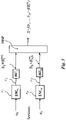
- Figure 1a shows the system scenario in which both aeronautical and fixed satellite services are served by the same forward link carrier.
- the aeronautical terminal is more susceptible to adjacent satellite interference due to less directivity of the antenna.
- the system scenario comprises two geo-stationary satellites, namely SAT1 and SAT2, an aero ST VLSNR receiver ARX and two Fixed station, namely a fixed station with a conventional receiver FXST1 and a fixed station with an advanced receiver FXST2.
- the first satellite SAT1 broadcasts the overlay signal
- the adjacent satellite SAT2 broadcasts the co-channel interference signal.
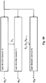
- Figure 1b shows the percentage of time for the different services.
- the two services AeroST VL-SNR and Fixed ST1 are equally distributed.
- AeroST + Fixed ST2 overlay signal has a higher percentage of use
- Table 1 summarizes the key system assumptions for two system solutions; one based on conventional ACM and time sharing and the second solution that uses similar time-sharing structure as solution one but replaces the VL-SNR modulation and coding with an overlay signal that is detected by aeronautical receiver as well as the receiver with interference cancellation capability.
- the frame structure is shown as already disclosed in Figure 1b .
- Transponder Bandwidth MHz 36 36
- a Ku-band transponder is considered 2
- the Link quality for fixed user terminal corresponds to 1,2 m dish size (G/T ⁇ 21 dB/K) and satellite EIRP of 41 dBW per transponder.
- the transponder bandwidth of 36 MHz is considered. Note that for fixed satellite terminals the co-channel interference due to the adjacent satellites is considered negligible.
- the overlay signal consists of two terms one decodable by Aero terminals with 90% of the signal power. The remaining power (10%) is used for the second layer that is only detectable and decodable by advanced fixed receivers. 5 SNR for Aero Terminal dB -3 -3,5 12 dB lower SNR compared to that of fixed satellite terminal. The C/N reduction of the overlay signal is due to power split between two signal layers.
- the transponder resources are shared between these two services.
- the transponder time is equally shared between the two services.
- the proposed overlay multiplexing solution for the sake of backward compatibility, the same conventional Fixed and Aero services are offered to the existing population of users (no change in the receivers are therefore required).
- a new class of fixed satellite terminals FXST2 are deployed that can decode and remove the Aero signal from an overlay signal and detect the second layer that is targeted for FXST2 terminals.
- the time-share between services (for the benchmark solution) and the power allocation (for the signal overlay solution) are adjusted such that the Aero terminals receive the same throughput for both benchmark and overlay solutions ( ⁇ 7,45 Mbits/s).
- the existing Fixed terminals can still be served by the TDM (with a slightly lower throughput).
- the co-channel interference due to the adjacent satellites is considered negligible.
- the C/N reduction of the overlay signal is due to power split between two signal layers. Due to the small size of the antenna, in this embodiment the adjacent satellite co-channel interference is present.
- the antenna has a wide beam and two adjacent satellites contribute to co-channel interference.
- the transponder resources can be shared between Aero terminal and the FXST2 terminals all the time).
- the overlay signal is designed to deliver service to Aero terminal continuously (no time sharing) as the primary service.
- the advanced receiver with a higher link quality reception can detect and remove the first layer of signal, then decode a second layer.
- Table 2 provides a summary of the (theoretical) results for this scenario.
- the aggregate throughput of the Aero services reaches 13,6 Mbits/s.
- the 10% of the power of the transponder is used to deliver 30,4 Mbits/s throughputs to high gain terminals.
- Table 2 No. Parameter Unit ACM (Benchmark) Signal Overlay Comment 1 Transponder Bandwidth MHz 36 36 A Ku-band transponder is considered 2 Typical Link Quality for fixed satellite services (C/N+I) dB 9 9
- the Link quality for fixed user terminal corresponds to 1,2 m dish size (G/T ⁇ 21 dB/K) and satellite EIRP of 41 dBW per transponder.
- the transponder bandwidth of 36 MHz is considered.
- Table 2 also includes the same analysis for ACM (with time sharing) solution.
- the ACM solution can only deliver 9,7 Mbits/s of fixed satellite service by utilizing 8,5% of the Time-sharing multiplex.
- the signal overlay transmission scheme does not introduce time jitter in bit delivery to high gain user terminals.
- the ACM solution in this example only occupies 8,5% of the transmission time for high gain terminals as shown in Figure 2b .
- the C/N reduction of the overlay signal is due to power split between two signal layers.
- the overlay signal constellation design at the transmitter and detection technique at the receiver is disclosed in order to realize the potential gain of the overlay signalling, particularly for application scenarios examples described in previous section.
- the set of N services are encoded by using independent powerful (turbo-like) binary codes ENC i with code rates r i , generating the sequence of coded bits c i that are interleaved INT i generating m i and sent to the mapper MAP.
- independent powerful (turbo-like) binary codes ENC i with code rates r i generating the sequence of coded bits c i that are interleaved INT i generating m i and sent to the mapper MAP.
- Figure 3 shows the block diagram of the transmitter general Hierarchical Modulation scheme.
- the N services u 1 ...u N are fed to a plurality of encoding blocks ENC 1 ... ENC N wherein each block applies the rates of the binary encoders r i in order to obtain the encoded bits c i .
- Said encoded bits c i are in turn fed to a plurality of interleave blocks INT 1 ...INT N , wherein in each interleave block INT i the encoded bits c i are grouped into blocks of m i bits.
- Each group of m i bits is fed to the MAP block.
- Figure 4 is the block diagram of the transmitter scheme with Superimposed Layer (SL).
- the set of N services are encoded by using independent powerful (turbo-like) binary codes ENC i with code rates r i , generating the sequence of coded bits c i that are interleaved INT i and sent to the group of mappers MAP i .
- each mapper MAP i referred as s i .
- s i The output of each mapper MAP i , referred as s i , is combined in an addition node ADD.
- the different proposed design solutions consider different adopted modulation sets, set of service rates and performance measures for the design of the transmitter.
- SM Superposition Modulation
- the Figure 5 shows the block diagram of the superposition modulator.
- the coefficient c ij is fed to the MAP block and reaches a S/P block which splits the coefficient over a plurality of branches B i .
- Each branch B i is multiplied for the coefficient ⁇ i and summed in order to obtain the value s i .
- the Superposition Modulation is then constructed using the same previously described for the broadcast channel for the superposition of services.
- the difference here is that bits used for constructing the modulation symbols are associated to the same service and thus generated by the same encoder.
- Figure 6 shows the block diagram of the transmitter scheme with SL and SM.
- FIG. 7 A block diagram of the proposed iterative receiver associated to the transmitter of Figure 3 or Figure 6 is shown in Figure 7 .
- Figure 7 shows the block diagram of a generic receiver for the superposition scheme of Figure 4 .
- the samples at the output of the matched filter r enter the block named "detector”, referred as DET that computes the Log-Likelihood Ratios (LLR) of the transmitted symbols ⁇ (s i ) for each service.
- the LLR symbols are converted to LLR bit by the Soft Output Mapper block (SOMAP), and then interleaved by block I/D, and the sequence of interleaved LLR bits enter the turbo decoder TDi associated to each service.
- SOMAP Soft Output Mapper block
- the superposition of services requires that iterations are performed between decoder and detector to achieve acceptable performance.
- the updated extrinsic from each decoder is fed back to the detector, which updates the LLR computation by exploiting the extrinsic information coming from other superimposed symbols.
- the SOMAP block computing the "LLR on bits” from the “LLR on symbols” can be merged into the detector block, yielding the receiver scheme of Figure 8a .
- Figure 8a shows the block diagram of a generic receiver for a broadcast channel with binary encoders and multiple services (Transmitters of Figure 6 and Figure 3 ).
- the detector block takes the samples r at the output of the channel and the extrinsic LLR on the m binary streams fed back from the N decoders and computes the updated extrinsic LLR.
- Figure 8b shows the structure of the layer decoder
- Figures 8c and 8d show embodiments of the i-th layer decoder and the i-th pragmatic layer decoder.
- the extrinsic information coming from the decoding of the first service is then used to compute the LLR for the next service and so on.
- extrinsic LLR are typically reliable and the optimal detector for the next binary stream actually corresponds to the cancellation of the decoded service.
- This approach delivers reliable output for the i-th service after exactly "i" detector iterations.
- the scheduling strategy for the full receiver thus requires to decide the order of execution of at least three decoding modules so as to achieve a fast convergence with the minimal amount of complexity.
- Scheduling optimization is then a rather complicated task, which also depends on the adopted architecture of the receiver, considering that also concurrent decoding processing is possible. In this preliminary investigation phase, it is considered few possible scheduling strategies, considering the performance and complexity trade-offs.
- a major source of complexity in the receiver of Figure 8a may derive from the operations performed in the detector block.
- APP optimal detector
- x ⁇ max x : B i 1 * log p a x p r
- a possible method to reduce the complexity of the optimal APP detector is to reduce the number of points in the modulation set used for the computation of LLR depending on the received samples. This idea is similar to the idea beyond the sphere decoder proposed as a suboptimal detector in the MIMO case.
- x ⁇ max x : c i , j 0 , x ⁇ r ⁇ ⁇ log p a x p r
- the interference from the other binary streams is eliminated using the available extrinsic information fed back from the binary decoder and modelling the digital interference as a Gaussian random variable.
- the value of means x ⁇ J and the variances ⁇ i 2 of interfering symbols are obtained from extrinsic information, used as a-priori information.
- the proposed hybrid detector approximates the probability density function (pdf) of residual interference by applying the Gaussian approximation on more reliable interfering symbols, while calculating the exact probability density function of unreliable interfering symbols.
- PDF probability density function
- Each scenario is described by providing the number of required services N, the relative rate of each service through a vector 1 , R 2 * / R 1 * , ... , R N * / R 1 * , the relative attenuation of each user class with respect to the worst one through the vector ⁇ 1 * / ⁇ 2 * , ... , ⁇ 1 * / ⁇ N * , the signal to noise ratio of the worst user class ⁇ , and the interference to noise ratio of the worst user ⁇ I .
- TX type TX type.
- the two encoding schemes of Figure 3 and Figure 6 are considered.
- the total number of bits of the modulation set m is fixed.
- a SIC receiver is considered, where each service is decoded sequentially. Also, pragmatic receivers are considered, where binary decoders are employed and no iterations take place on a single service between detector and decoder.
- Peak power constraint and average power constraint Two types of power constraint were considered. Peak power constraint and average power constraint.
- the modulation set is designed, the corresponding binary labelling and the optimal allocation vector of modulation bits to service (m 1 ...m N ) so that the vector of average mutual information under ideal SIC decoding for each service (I 1 ...I Ns ) satisfies I 1 , ... , I N s ⁇ ⁇ 1 , ... , R N * / R 1 * with ⁇ as large as possible.
- Figure 9 shows the general structure of the designed TX system.
- the vector x has 2 ⁇ 2 m real dimensions.
- the quadrant symmetry condition is adopted, imposing symmetry of the constellation to reflections to both axes.
- the design space has then dimensionality four for the general case and six for Superposition Modulation.
- the design space has dimensionality eight for the general case and eight for Superposition Modulation.
- the design space has then dimensionality sixteen for the general case and ten for Superposition Modulation.
- the optimized constellation will be then able to support the rate vector I 1 SIC b ... , I N SIC b ⁇ ⁇ SIC b R 1 * , ... , R N s * .
- the only modification to adopt in the constellation optimization stage is to substitute a peak power constraint to the usual average power constraint.
- Figure 10 shows the soft limiter modelling the non-linearity.
- the peak power of the constellation becomes the relevant parameter.
- SA simulation annealing
- the random perturbation ⁇ (n) is performed by picking a uniformly random element of the solution vector x and randomly moving it in an interval that depends on the current temperature: x R ⁇ x R + 2 D 0 t n U ⁇ 0.5 where R is a discrete uniform random variable in [1,...,N] and U is a uniform random variable in [0,1[.
- the proposed solution discloses a method for design an optimized constellation set and labeling for satellite point to multi-point transmission systems comprising transmitters and receivers.
- the transmitters are adapted to create signals overlay and are configured to allow simultaneous transmission of at least two different data streams (services) intended for users with different radio link qualities.
- the N services are provided to users having a good radio link and a subset of services is maintained and guaranteed for the users having a lower radio link quality condition.
- the channel and traffic scenario is described by providing the number of required services N, the relative required throughput of each service through a first vector 1 , R 2 * / R 1 * , ... , R N * / R 1 * , the relative attenuation of each user class with respect to the worst one through a second vector ⁇ 1 * / ⁇ 2 * , ... , ⁇ 1 * / ⁇ N * , the signal to noise ratio of the worst user class ⁇ , and the interference to noise ratio of the worst user ⁇ I .
- the system comprises a plurality of receivers, and each receiver is configured for allowing the decoding of one or more overlay services in a cascade "onion peeling" manner.
- each receiver starts decoding the first service with the lowest detection threshold in terms of required signal quality and proceeds to the following layers decoders when reliable decisions are available on bits at previous layer.
- the maximum number of services that can be decoded depends on the user radio link quality.
- the method for design the optimized constellation set comprises the steps of:
- a maximization is performed with a simulated annealing technique and the mutual information values I i are used to select the required code rates as r i ⁇ I i / m i .
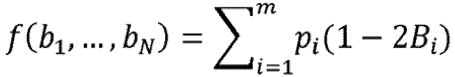
- the power constraint is selected as peak power constraint according to max B 1 m f B 1 m ⁇ P .
- the power constraint is selected as average power constraint according to 1 M ⁇ B 1 m f B 1 m ⁇ P .
- each receiver comprises a pragmatic layer decoder, wherein no iteration takes place between the binary decoder and the detector block.
- B 1 n i ⁇ 1 where Y i f( B ) + N i and N i is a gaussian random variable with variance computed according to radio link quality associated to the target users of the i-th service.
- B 1 n i ⁇ 1 wherein Y i f ( B ) + N i and N i is a gaussian random variable with variance computed according to radio link quality associated to the target users of the i-th service.
- the set of parameters ⁇ defining the mapping is reduced by forcing one or more of the constellation sets f i to some predetermined constellation set.
- the solution describes also a system wherein the transmitter adopts a constellation set that has been designed according to the disclosed method.
Landscapes
- Engineering & Computer Science (AREA)
- Computer Networks & Wireless Communication (AREA)
- Signal Processing (AREA)
- Physics & Mathematics (AREA)
- Astronomy & Astrophysics (AREA)
- Aviation & Aerospace Engineering (AREA)
- General Physics & Mathematics (AREA)
- Digital Transmission Methods That Use Modulated Carrier Waves (AREA)
- Radio Relay Systems (AREA)
Claims (9)
- Procédé de conception d'un ensemble optimisé de points de constellation et d'étiquetage pour des systèmes d'émission point à multipoint par satellite comprenant des émetteurs et des récepteurs, dans lequel lesdits émetteurs sont conçus pour créer une superposition de signaux et sont configurés pour permettre l'émission simultanée d'au moins deux flux de données différents associés à des services (Services) respectifs destinés à des utilisateurs avec des qualités de liaison radio différentes, dans lequel N services sont fournis à des utilisateurs ayant une bonne liaison radio et un sous-ensemble de services est maintenu et garanti pour les utilisateurs ayant une condition de qualité de liaison radio inférieure, dans lequel ledit système comprend :- décrire le scénario de canal et de trafic en fournissant le nombre de services requis N, le débit requis relatif de chaque service par l'intermédiaire d'un premier vecteur (1, R*2/R*1,..., R*N/R*1), l'atténuation relative de chaque classe d'utilisateurs par rapport à la pire par l'intermédiaire d'un second vecteur (α*1/α*2,..., α*1/α*N), le rapport signal sur bruit de la pire classe d'utilisateurs Γ et le rapport interférence sur bruit du pire utilisateur ΓI ;- un émetteur, configuré pour coder les flux de données de l'ensemble de N services en utilisant des codes binaires puissants indépendants (ENCi) avec des taux de codage (ri), générant la séquence de bits codés ci qui sont entrelacés (INTi) générant une séquence de blocs de mi bits bi, où bi =


 - une pluralité de récepteurs, chaque récepteur étant configuré pour permettre le décodage d'un ou plusieurs services de superposition à la manière d'un "oignonage" en cascade, chaque récepteur commençant à décoder le premier service avec le seuil de détection le plus bas en termes de qualité de signal requise et passant aux décodeurs des couches suivantes lorsque des décisions fiables sont disponibles sur les bits à la couche précédente, et le nombre maximal de services qui peuvent être décodés dépendant de la qualité de liaison radio d'utilisateur, et le décodeur de la ième couche n'étant activé que si l'étape de décodage de la couche i-1 précédente est réussie et exploitant les estimations fiables de tous les bitsle procédé de conception d'un ensemble de constellation optimisé comprenant les étapes suivantes :
 - sélectionner une cardinalité de constellation de M = 2m ;- sélectionner une répartition de bits de modulation mi : ∑ i mi = m vers des services ;- sélectionner une contrainte de puissance, la contrainte de puissance étant sélectionnée comme contrainte de puissance de crête selon
 - sélectionner une structure cible pour les décodeurs de couches dans tous les récepteurs ;- sélectionner une structure pour le mappage f(b1,...,bN) caractérisée par un ensemble de paramètres a,l'ensemble de paramètres a étant sélectionné afin de satisfaire la contrainte de puissance rendant maximale la valeur de β comme suit :
 - le Ii étant la valeur d'informations mutuelles associée à la ième couche, en fonction des paramètres de système ;- une maximisation étant effectuée avec une technique de recuit simulé ; et- les valeurs d'informations mutuelles Ii étant utilisées pour sélectionner les taux de codage requis comme suit ri ≤ Ii /mi .
 - Procédé selon la revendication 1, dans lequel chaque récepteur comprend un décodeur de couche pragmatique, et dans lequel, dans ledit décodeur de couche pragmatique, aucune itération n'a lieu entre le décodeur binaire et le bloc de détecteur, et dans lequel les informations mutuelles cibles de la ième couche sont calculées comme suit :

- Procédé selon la revendication 1, dans lequel les récepteurs comprennent des décodeurs de couche optimaux et la valeur d'informations mutuelles cibles de la ième couche est calculée comme suit :

- Procédé selon la revendication 1, dans lequel le mappage f est général et le jeu de paramètres a est la liste de M = 2m coordonnées complexes des points de l'ensemble de constellation.
- Procédé selon la revendication 4, dans lequel une symétrie quadrant est sélectionnée pour l'ensemble de constellation, et l'ensemble de paramètres a est la liste des M/4 premières coordonnées complexes de l'ensemble de constellation, et les restants sont obtenus par symétrie comme suit :
pour tout


- Procédé selon la revendication 1, dans lequel le mappage f est la superposition de couches avec une modulation générale pour chaque couche.

- Procédé selon la revendication 1, dans lequel le mappage f est une superposition de couches, et chaque couche utilise un ensemble de constellation obtenu comme la superposition de modulations binaires
- Procédé selon la revendication 7, dans lequel l'ensemble de paramètres a définissant le mappage est réduit en forçant un ou plusieurs des ensembles de constellation fi à un certain ensemble de constellation prédéterminé.
- Système comprenant un émetteur, dans lequel l'émetteur est configuré pour utiliser un ensemble de constellation qui a été conçu selon les étapes de procédé d'émetteur selon l'une quelconque des revendications 1 à 8.
Applications Claiming Priority (2)
| Application Number | Priority Date | Filing Date | Title |
|---|---|---|---|
| IT102017000113326A IT201700113326A1 (it) | 2017-10-09 | 2017-10-09 | “Progettazione e rilevamento della sovrapposizione di segnali per canali di comunicazione satellitari” |
| PCT/IB2018/057775 WO2019073354A1 (fr) | 2017-10-09 | 2018-10-08 | Conception et détection de superposition de signaux pour canaux de communication par satellite |
Publications (2)
| Publication Number | Publication Date |
|---|---|
| EP3695534A1 EP3695534A1 (fr) | 2020-08-19 |
| EP3695534B1 true EP3695534B1 (fr) | 2022-06-29 |
Family
ID=61148406
Family Applications (1)
| Application Number | Title | Priority Date | Filing Date |
|---|---|---|---|
| EP18789487.8A Active EP3695534B1 (fr) | 2017-10-09 | 2018-10-08 | Conception et détection de superposition de signaux pour canaux de communication par satellite |
Country Status (4)
| Country | Link |
|---|---|
| US (1) | US11101878B2 (fr) |
| EP (1) | EP3695534B1 (fr) |
| IT (1) | IT201700113326A1 (fr) |
| WO (1) | WO2019073354A1 (fr) |
Families Citing this family (3)
| Publication number | Priority date | Publication date | Assignee | Title |
|---|---|---|---|---|
| CN113141206B (zh) * | 2021-04-20 | 2022-03-22 | 哈尔滨工业大学(威海) | 一种微纳星群星间链路自适应通信方法及系统 |
| US20230004412A1 (en) * | 2021-06-30 | 2023-01-05 | International Business Machines Corporation | Quantifying service chain functions of virtual machines for cross interferences |
| CN115695133A (zh) * | 2022-10-28 | 2023-02-03 | 南京理工大学 | 一种理想信道估计下高维调制noma的分配方案 |
Family Cites Families (2)
| Publication number | Priority date | Publication date | Assignee | Title |
|---|---|---|---|---|
| US20150146546A1 (en) * | 2013-11-22 | 2015-05-28 | Huawei Technologies Co., Ltd. | Method and nodes in a wireless communication system |
| EP3632024A1 (fr) * | 2017-05-26 | 2020-04-08 | Telefonaktiebolaget LM Ericsson (publ) | Signalisation non orthogonale pour réseaux d'accès radio |
-
2017
- 2017-10-09 IT IT102017000113326A patent/IT201700113326A1/it unknown
-
2018
- 2018-10-08 US US16/754,616 patent/US11101878B2/en active Active
- 2018-10-08 EP EP18789487.8A patent/EP3695534B1/fr active Active
- 2018-10-08 WO PCT/IB2018/057775 patent/WO2019073354A1/fr unknown
Also Published As
| Publication number | Publication date |
|---|---|
| WO2019073354A1 (fr) | 2019-04-18 |
| US11101878B2 (en) | 2021-08-24 |
| EP3695534A1 (fr) | 2020-08-19 |
| US20200358521A1 (en) | 2020-11-12 |
| IT201700113326A1 (it) | 2019-04-09 |
Similar Documents
| Publication | Publication Date | Title |
|---|---|---|
| Park et al. | Low complexity layered division multiplexing for ATSC 3.0 | |
| US7623589B2 (en) | Cooperative multiple-access using user-clustering and space-time-frequency coding techniques for higher reliability reception | |
| US7110462B2 (en) | Multiple access system and method for multibeam digital radio systems | |
| JP3464981B2 (ja) | 情報送信装置及びその方法並びに情報受信装置及びその方法 | |
| US10263814B2 (en) | Method and system for providing scrambled coded multiple access (SCMA) | |
| Colavolpe et al. | Multiuser detection in multibeam satellite systems: Theoretical analysis and practical schemes | |
| EP3695534B1 (fr) | Conception et détection de superposition de signaux pour canaux de communication par satellite | |
| US7072410B1 (en) | Multiple access system and method for multibeam digital radio systems | |
| JP2003529951A (ja) | ディジタル放送システム及び方法 | |
| EA024829B1 (ru) | Передатчик и способ передачи | |
| Henarejos et al. | Dual polarized modulation and reception for next generation mobile satellite communications | |
| Caus et al. | An innovative interference mitigation approach for high throughput satellite systems | |
| Ng et al. | Minimum expected distortion in Gaussian layered broadcast coding with successive refinement | |
| Azzahra | NOMA signal transmission over millimeter-wave frequency for backbone network in HAPS with MIMO antenna | |
| US7298696B1 (en) | Blockage mitigation techniques for information transmission | |
| Kotak et al. | Simulation & performance analysis of DVB-T system using efficient wireless channels | |
| Heuberger | Fade correlation and diversity effects in satellite broadcasting to mobile users in S‐band | |
| Agarwal et al. | Variable rate multicarrier schemes over integrated satellite-terrestrial system | |
| Alagha et al. | Optimized non-orthogonal multiplexing in Peak Power Limited Channels | |
| US10587334B2 (en) | Method and a system for use in a satellite communications system | |
| Stallo et al. | Link performance analysis of multi-user detection techniques for W-band multi-beam satellites | |
| JP2002164906A (ja) | 相異なる種類の端末を有するポイントツーマルチポイント無線通信システムでチャネル容量を増加させる方法およびシステム | |
| Martin et al. | Statistical analysis and optimal design for efficient mobile satellite broadcast with diversity | |
| Abass et al. | Coded-beam Strategy for High Throughput Satellites-A Path Toward Terahertz Communications-System Model, Realization and Performance Assessment | |
| GB2510657A (en) | Spread spectrum communication system with separate spreading codes for header and payload portions |
Legal Events
| Date | Code | Title | Description |
|---|---|---|---|
| STAA | Information on the status of an ep patent application or granted ep patent |
Free format text: STATUS: UNKNOWN |
|
| STAA | Information on the status of an ep patent application or granted ep patent |
Free format text: STATUS: THE INTERNATIONAL PUBLICATION HAS BEEN MADE |
|
| PUAI | Public reference made under article 153(3) epc to a published international application that has entered the european phase |
Free format text: ORIGINAL CODE: 0009012 |
|
| STAA | Information on the status of an ep patent application or granted ep patent |
Free format text: STATUS: REQUEST FOR EXAMINATION WAS MADE |
|
| 17P | Request for examination filed |
Effective date: 20200508 |
|
| AK | Designated contracting states |
Kind code of ref document: A1 Designated state(s): AL AT BE BG CH CY CZ DE DK EE ES FI FR GB GR HR HU IE IS IT LI LT LU LV MC MK MT NL NO PL PT RO RS SE SI SK SM TR |
|
| AX | Request for extension of the european patent |
Extension state: BA ME |
|
| DAV | Request for validation of the european patent (deleted) | ||
| DAX | Request for extension of the european patent (deleted) | ||
| GRAP | Despatch of communication of intention to grant a patent |
Free format text: ORIGINAL CODE: EPIDOSNIGR1 |
|
| STAA | Information on the status of an ep patent application or granted ep patent |
Free format text: STATUS: GRANT OF PATENT IS INTENDED |
|
| INTG | Intention to grant announced |
Effective date: 20211208 |
|
| GRAS | Grant fee paid |
Free format text: ORIGINAL CODE: EPIDOSNIGR3 |
|
| GRAA | (expected) grant |
Free format text: ORIGINAL CODE: 0009210 |
|
| STAA | Information on the status of an ep patent application or granted ep patent |
Free format text: STATUS: THE PATENT HAS BEEN GRANTED |
|
| AK | Designated contracting states |
Kind code of ref document: B1 Designated state(s): AL AT BE BG CH CY CZ DE DK EE ES FI FR GB GR HR HU IE IS IT LI LT LU LV MC MK MT NL NO PL PT RO RS SE SI SK SM TR |
|
| RAP1 | Party data changed (applicant data changed or rights of an application transferred) |
Owner name: EUROPEAN SPACE AGENCY |
|
| REG | Reference to a national code |
Ref country code: CH Ref legal event code: EP |
|
| REG | Reference to a national code |
Ref country code: AT Ref legal event code: REF Ref document number: 1502021 Country of ref document: AT Kind code of ref document: T Effective date: 20220715 |
|
| REG | Reference to a national code |
Ref country code: IE Ref legal event code: FG4D |
|
| REG | Reference to a national code |
Ref country code: DE Ref legal event code: R096 Ref document number: 602018037372 Country of ref document: DE |
|
| REG | Reference to a national code |
Ref country code: LT Ref legal event code: MG9D |
|
| PG25 | Lapsed in a contracting state [announced via postgrant information from national office to epo] |
Ref country code: SE Free format text: LAPSE BECAUSE OF FAILURE TO SUBMIT A TRANSLATION OF THE DESCRIPTION OR TO PAY THE FEE WITHIN THE PRESCRIBED TIME-LIMIT Effective date: 20220629 Ref country code: NO Free format text: LAPSE BECAUSE OF FAILURE TO SUBMIT A TRANSLATION OF THE DESCRIPTION OR TO PAY THE FEE WITHIN THE PRESCRIBED TIME-LIMIT Effective date: 20220929 Ref country code: LT Free format text: LAPSE BECAUSE OF FAILURE TO SUBMIT A TRANSLATION OF THE DESCRIPTION OR TO PAY THE FEE WITHIN THE PRESCRIBED TIME-LIMIT Effective date: 20220629 Ref country code: HR Free format text: LAPSE BECAUSE OF FAILURE TO SUBMIT A TRANSLATION OF THE DESCRIPTION OR TO PAY THE FEE WITHIN THE PRESCRIBED TIME-LIMIT Effective date: 20220629 Ref country code: GR Free format text: LAPSE BECAUSE OF FAILURE TO SUBMIT A TRANSLATION OF THE DESCRIPTION OR TO PAY THE FEE WITHIN THE PRESCRIBED TIME-LIMIT Effective date: 20220930 Ref country code: FI Free format text: LAPSE BECAUSE OF FAILURE TO SUBMIT A TRANSLATION OF THE DESCRIPTION OR TO PAY THE FEE WITHIN THE PRESCRIBED TIME-LIMIT Effective date: 20220629 Ref country code: BG Free format text: LAPSE BECAUSE OF FAILURE TO SUBMIT A TRANSLATION OF THE DESCRIPTION OR TO PAY THE FEE WITHIN THE PRESCRIBED TIME-LIMIT Effective date: 20220929 |
|
| REG | Reference to a national code |
Ref country code: NL Ref legal event code: MP Effective date: 20220629 |
|
| REG | Reference to a national code |
Ref country code: AT Ref legal event code: MK05 Ref document number: 1502021 Country of ref document: AT Kind code of ref document: T Effective date: 20220629 |
|
| PG25 | Lapsed in a contracting state [announced via postgrant information from national office to epo] |
Ref country code: RS Free format text: LAPSE BECAUSE OF FAILURE TO SUBMIT A TRANSLATION OF THE DESCRIPTION OR TO PAY THE FEE WITHIN THE PRESCRIBED TIME-LIMIT Effective date: 20220629 Ref country code: LV Free format text: LAPSE BECAUSE OF FAILURE TO SUBMIT A TRANSLATION OF THE DESCRIPTION OR TO PAY THE FEE WITHIN THE PRESCRIBED TIME-LIMIT Effective date: 20220629 |
|
| PG25 | Lapsed in a contracting state [announced via postgrant information from national office to epo] |
Ref country code: NL Free format text: LAPSE BECAUSE OF FAILURE TO SUBMIT A TRANSLATION OF THE DESCRIPTION OR TO PAY THE FEE WITHIN THE PRESCRIBED TIME-LIMIT Effective date: 20220629 |
|
| PG25 | Lapsed in a contracting state [announced via postgrant information from national office to epo] |
Ref country code: SM Free format text: LAPSE BECAUSE OF FAILURE TO SUBMIT A TRANSLATION OF THE DESCRIPTION OR TO PAY THE FEE WITHIN THE PRESCRIBED TIME-LIMIT Effective date: 20220629 Ref country code: SK Free format text: LAPSE BECAUSE OF FAILURE TO SUBMIT A TRANSLATION OF THE DESCRIPTION OR TO PAY THE FEE WITHIN THE PRESCRIBED TIME-LIMIT Effective date: 20220629 Ref country code: RO Free format text: LAPSE BECAUSE OF FAILURE TO SUBMIT A TRANSLATION OF THE DESCRIPTION OR TO PAY THE FEE WITHIN THE PRESCRIBED TIME-LIMIT Effective date: 20220629 Ref country code: PT Free format text: LAPSE BECAUSE OF FAILURE TO SUBMIT A TRANSLATION OF THE DESCRIPTION OR TO PAY THE FEE WITHIN THE PRESCRIBED TIME-LIMIT Effective date: 20221031 Ref country code: ES Free format text: LAPSE BECAUSE OF FAILURE TO SUBMIT A TRANSLATION OF THE DESCRIPTION OR TO PAY THE FEE WITHIN THE PRESCRIBED TIME-LIMIT Effective date: 20220629 Ref country code: EE Free format text: LAPSE BECAUSE OF FAILURE TO SUBMIT A TRANSLATION OF THE DESCRIPTION OR TO PAY THE FEE WITHIN THE PRESCRIBED TIME-LIMIT Effective date: 20220629 Ref country code: AT Free format text: LAPSE BECAUSE OF FAILURE TO SUBMIT A TRANSLATION OF THE DESCRIPTION OR TO PAY THE FEE WITHIN THE PRESCRIBED TIME-LIMIT Effective date: 20220629 |
|
| PG25 | Lapsed in a contracting state [announced via postgrant information from national office to epo] |
Ref country code: PL Free format text: LAPSE BECAUSE OF FAILURE TO SUBMIT A TRANSLATION OF THE DESCRIPTION OR TO PAY THE FEE WITHIN THE PRESCRIBED TIME-LIMIT Effective date: 20220629 Ref country code: IS Free format text: LAPSE BECAUSE OF FAILURE TO SUBMIT A TRANSLATION OF THE DESCRIPTION OR TO PAY THE FEE WITHIN THE PRESCRIBED TIME-LIMIT Effective date: 20221029 |
|
| REG | Reference to a national code |
Ref country code: DE Ref legal event code: R097 Ref document number: 602018037372 Country of ref document: DE |
|
| PG25 | Lapsed in a contracting state [announced via postgrant information from national office to epo] |
Ref country code: AL Free format text: LAPSE BECAUSE OF FAILURE TO SUBMIT A TRANSLATION OF THE DESCRIPTION OR TO PAY THE FEE WITHIN THE PRESCRIBED TIME-LIMIT Effective date: 20220629 |
|
| PG25 | Lapsed in a contracting state [announced via postgrant information from national office to epo] |
Ref country code: DK Free format text: LAPSE BECAUSE OF FAILURE TO SUBMIT A TRANSLATION OF THE DESCRIPTION OR TO PAY THE FEE WITHIN THE PRESCRIBED TIME-LIMIT Effective date: 20220629 Ref country code: CZ Free format text: LAPSE BECAUSE OF FAILURE TO SUBMIT A TRANSLATION OF THE DESCRIPTION OR TO PAY THE FEE WITHIN THE PRESCRIBED TIME-LIMIT Effective date: 20220629 |
|
| PGFP | Annual fee paid to national office [announced via postgrant information from national office to epo] |
Ref country code: FR Payment date: 20230123 Year of fee payment: 6 |
|
| PLBE | No opposition filed within time limit |
Free format text: ORIGINAL CODE: 0009261 |
|
| STAA | Information on the status of an ep patent application or granted ep patent |
Free format text: STATUS: NO OPPOSITION FILED WITHIN TIME LIMIT |
|
| PG25 | Lapsed in a contracting state [announced via postgrant information from national office to epo] |
Ref country code: MC Free format text: LAPSE BECAUSE OF FAILURE TO SUBMIT A TRANSLATION OF THE DESCRIPTION OR TO PAY THE FEE WITHIN THE PRESCRIBED TIME-LIMIT Effective date: 20220629 |
|
| REG | Reference to a national code |
Ref country code: CH Ref legal event code: PL |
|
| 26N | No opposition filed |
Effective date: 20230330 |
|
| REG | Reference to a national code |
Ref country code: BE Ref legal event code: MM Effective date: 20221031 |
|
| PG25 | Lapsed in a contracting state [announced via postgrant information from national office to epo] |
Ref country code: LU Free format text: LAPSE BECAUSE OF NON-PAYMENT OF DUE FEES Effective date: 20221008 |
|
| PG25 | Lapsed in a contracting state [announced via postgrant information from national office to epo] |
Ref country code: LI Free format text: LAPSE BECAUSE OF NON-PAYMENT OF DUE FEES Effective date: 20221031 Ref country code: CH Free format text: LAPSE BECAUSE OF NON-PAYMENT OF DUE FEES Effective date: 20221031 |
|
| PG25 | Lapsed in a contracting state [announced via postgrant information from national office to epo] |
Ref country code: SI Free format text: LAPSE BECAUSE OF FAILURE TO SUBMIT A TRANSLATION OF THE DESCRIPTION OR TO PAY THE FEE WITHIN THE PRESCRIBED TIME-LIMIT Effective date: 20220629 |
|
| PG25 | Lapsed in a contracting state [announced via postgrant information from national office to epo] |
Ref country code: BE Free format text: LAPSE BECAUSE OF NON-PAYMENT OF DUE FEES Effective date: 20221031 |
|
| PG25 | Lapsed in a contracting state [announced via postgrant information from national office to epo] |
Ref country code: IE Free format text: LAPSE BECAUSE OF NON-PAYMENT OF DUE FEES Effective date: 20221008 |
|
| PGFP | Annual fee paid to national office [announced via postgrant information from national office to epo] |
Ref country code: GB Payment date: 20231020 Year of fee payment: 6 |
|
| PG25 | Lapsed in a contracting state [announced via postgrant information from national office to epo] |
Ref country code: IT Free format text: LAPSE BECAUSE OF FAILURE TO SUBMIT A TRANSLATION OF THE DESCRIPTION OR TO PAY THE FEE WITHIN THE PRESCRIBED TIME-LIMIT Effective date: 20220629 |
|
| PGFP | Annual fee paid to national office [announced via postgrant information from national office to epo] |
Ref country code: DE Payment date: 20230123 Year of fee payment: 6 |
|
| PG25 | Lapsed in a contracting state [announced via postgrant information from national office to epo] |
Ref country code: CY Free format text: LAPSE BECAUSE OF FAILURE TO SUBMIT A TRANSLATION OF THE DESCRIPTION OR TO PAY THE FEE WITHIN THE PRESCRIBED TIME-LIMIT Effective date: 20220629 |