EP3695387B1 - Verfahren zur darstellung von bildern eines kamerasystems eines fahrzeugs - Google Patents
Verfahren zur darstellung von bildern eines kamerasystems eines fahrzeugs Download PDFInfo
- Publication number
- EP3695387B1 EP3695387B1 EP18772764.9A EP18772764A EP3695387B1 EP 3695387 B1 EP3695387 B1 EP 3695387B1 EP 18772764 A EP18772764 A EP 18772764A EP 3695387 B1 EP3695387 B1 EP 3695387B1
- Authority
- EP
- European Patent Office
- Prior art keywords
- virtual
- vehicle
- dimensional objects
- predefined
- textures
- Prior art date
- Legal status (The legal status is an assumption and is not a legal conclusion. Google has not performed a legal analysis and makes no representation as to the accuracy of the status listed.)
- Active
Links
Images



Classifications
-
- G—PHYSICS
- G06—COMPUTING OR CALCULATING; COUNTING
- G06T—IMAGE DATA PROCESSING OR GENERATION, IN GENERAL
- G06T19/00—Manipulating three-dimensional [3D] models or images for computer graphics
- G06T19/20—Editing of three-dimensional [3D] images, e.g. changing shapes or colours, aligning objects or positioning parts
-
- H—ELECTRICITY
- H04—ELECTRIC COMMUNICATION TECHNIQUE
- H04N—PICTORIAL COMMUNICATION, e.g. TELEVISION
- H04N13/00—Stereoscopic video systems; Multi-view video systems; Details thereof
- H04N13/10—Processing, recording or transmission of stereoscopic or multi-view image signals
- H04N13/106—Processing image signals
- H04N13/111—Transformation of image signals corresponding to virtual viewpoints, e.g. spatial image interpolation
-
- B—PERFORMING OPERATIONS; TRANSPORTING
- B60—VEHICLES IN GENERAL
- B60R—VEHICLES, VEHICLE FITTINGS, OR VEHICLE PARTS, NOT OTHERWISE PROVIDED FOR
- B60R1/00—Optical viewing arrangements; Real-time viewing arrangements for drivers or passengers using optical image capturing systems, e.g. cameras or video systems specially adapted for use in or on vehicles
- B60R1/20—Real-time viewing arrangements for drivers or passengers using optical image capturing systems, e.g. cameras or video systems specially adapted for use in or on vehicles
- B60R1/22—Real-time viewing arrangements for drivers or passengers using optical image capturing systems, e.g. cameras or video systems specially adapted for use in or on vehicles for viewing an area outside the vehicle, e.g. the exterior of the vehicle
- B60R1/23—Real-time viewing arrangements for drivers or passengers using optical image capturing systems, e.g. cameras or video systems specially adapted for use in or on vehicles for viewing an area outside the vehicle, e.g. the exterior of the vehicle with a predetermined field of view
- B60R1/27—Real-time viewing arrangements for drivers or passengers using optical image capturing systems, e.g. cameras or video systems specially adapted for use in or on vehicles for viewing an area outside the vehicle, e.g. the exterior of the vehicle with a predetermined field of view providing all-round vision, e.g. using omnidirectional cameras
-
- G—PHYSICS
- G06—COMPUTING OR CALCULATING; COUNTING
- G06T—IMAGE DATA PROCESSING OR GENERATION, IN GENERAL
- G06T15/00—Three-dimensional [3D] image rendering
- G06T15/04—Texture mapping
-
- G—PHYSICS
- G08—SIGNALLING
- G08G—TRAFFIC CONTROL SYSTEMS
- G08G1/00—Traffic control systems for road vehicles
- G08G1/14—Traffic control systems for road vehicles indicating individual free spaces in parking areas
- G08G1/141—Traffic control systems for road vehicles indicating individual free spaces in parking areas with means giving the indication of available parking spaces
- G08G1/143—Traffic control systems for road vehicles indicating individual free spaces in parking areas with means giving the indication of available parking spaces inside the vehicles
-
- H—ELECTRICITY
- H04—ELECTRIC COMMUNICATION TECHNIQUE
- H04N—PICTORIAL COMMUNICATION, e.g. TELEVISION
- H04N13/00—Stereoscopic video systems; Multi-view video systems; Details thereof
- H04N13/10—Processing, recording or transmission of stereoscopic or multi-view image signals
- H04N13/106—Processing image signals
- H04N13/15—Processing image signals for colour aspects of image signals
-
- H—ELECTRICITY
- H04—ELECTRIC COMMUNICATION TECHNIQUE
- H04N—PICTORIAL COMMUNICATION, e.g. TELEVISION
- H04N13/00—Stereoscopic video systems; Multi-view video systems; Details thereof
- H04N13/20—Image signal generators
- H04N13/282—Image signal generators for generating image signals corresponding to three or more geometrical viewpoints, e.g. multi-view systems
-
- H—ELECTRICITY
- H04—ELECTRIC COMMUNICATION TECHNIQUE
- H04N—PICTORIAL COMMUNICATION, e.g. TELEVISION
- H04N23/00—Cameras or camera modules comprising electronic image sensors; Control thereof
- H04N23/60—Control of cameras or camera modules
- H04N23/698—Control of cameras or camera modules for achieving an enlarged field of view, e.g. panoramic image capture
-
- B—PERFORMING OPERATIONS; TRANSPORTING
- B60—VEHICLES IN GENERAL
- B60R—VEHICLES, VEHICLE FITTINGS, OR VEHICLE PARTS, NOT OTHERWISE PROVIDED FOR
- B60R2300/00—Details of viewing arrangements using cameras and displays, specially adapted for use in a vehicle
- B60R2300/10—Details of viewing arrangements using cameras and displays, specially adapted for use in a vehicle characterised by the type of camera system used
-
- B—PERFORMING OPERATIONS; TRANSPORTING
- B60—VEHICLES IN GENERAL
- B60R—VEHICLES, VEHICLE FITTINGS, OR VEHICLE PARTS, NOT OTHERWISE PROVIDED FOR
- B60R2300/00—Details of viewing arrangements using cameras and displays, specially adapted for use in a vehicle
- B60R2300/20—Details of viewing arrangements using cameras and displays, specially adapted for use in a vehicle characterised by the type of display used
-
- B—PERFORMING OPERATIONS; TRANSPORTING
- B60—VEHICLES IN GENERAL
- B60R—VEHICLES, VEHICLE FITTINGS, OR VEHICLE PARTS, NOT OTHERWISE PROVIDED FOR
- B60R2300/00—Details of viewing arrangements using cameras and displays, specially adapted for use in a vehicle
- B60R2300/30—Details of viewing arrangements using cameras and displays, specially adapted for use in a vehicle characterised by the type of image processing
- B60R2300/307—Details of viewing arrangements using cameras and displays, specially adapted for use in a vehicle characterised by the type of image processing virtually distinguishing relevant parts of a scene from the background of the scene
-
- G—PHYSICS
- G06—COMPUTING OR CALCULATING; COUNTING
- G06T—IMAGE DATA PROCESSING OR GENERATION, IN GENERAL
- G06T2219/00—Indexing scheme for manipulating 3D models or images for computer graphics
- G06T2219/004—Annotating, labelling
Definitions
- the present invention relates to a method for displaying images from a camera system of a vehicle.
- the camera system is an all-round vision system that can capture images around a vehicle.
- Such all-round vision systems are known from the state of the art as surround view systems (SVS).
- SVS surround view systems
- the following publications describe such systems: " 360 Wrap-Around Video Imaging Technology Ready for Integration with Fujitsu Graphics SoCs", January 2014 ; Esparza Garcia: “3D Reconstruction for Optimal Representation of Surroundings in Automotive HMIs, Based on Fisheye Multicamera Systems", PhD thesis 2015 .
- Such systems use different data types to display a maximum amount of information. In this way, the driver is shown the maximum amount of information that the system can provide.
- Such data types can be obtained in particular from sensor data fusions, from information in a cloud, and from many other sources.
- Typical data from sensor data fusions includes information about occupied and free areas around the vehicle, which is determined using video sensors, radar sensors, lidar sensors or other environmental sensors of the vehicle. Information from a cloud can in particular be weather conditions and available parking spaces.
- the large amount of information that the SVS is supposed to display can overwhelm the vehicle driver if it is not displayed appropriately. This means that data is recorded unnecessarily that does not provide any added value to the driver because he does not recognize the information.
- the current technology requires considerable computing effort to create a very complex display that integrates all the information available to the surround view system into one display image. However, this considerable computing effort is often not necessary to show the driver the currently relevant information.
- the invention is defined by the independent claims.
- the method according to the invention enables information to be displayed in different representations.
- the representations are determined using a selection criterion. In this way, on the one hand, it is possible to only display relevant information to the driver, and on the other hand, the computing power of the system generating the counter-representation is significantly reduced.
- the method according to the invention for displaying images from a camera system of a vehicle is intended for the purpose of displaying obstacles from the surroundings of the vehicle detected by said camera system on a display device.
- the display takes place in a virtual three-dimensional space.
- the detected obstacles are displayed as virtual three-dimensional objects.
- the viewer thus has the impression that this is a spatial display in which spatial objects are displayed. This corresponds to a virtual view of the actual scenery from a corresponding virtual camera position.
- the driver of the vehicle can thus be provided with an overview of the current scenery.
- a selection criterion is used to determine whether the virtual three-dimensional objects and/or the virtual three-dimensional space are covered with textures generated by the camera system or are covered with at least one predefined texture.
- the predefined texture can also be a single color in different shades, so that no texture is displayed on the display device.
- the selection criterion is used to determine whether the textures intended to cover the virtual three-dimensional objects and/or the virtual three-dimensional space are processed using a predefined filter.
- the contrast of the textures can be increased using the predefined filter. This means that it is still possible to display textures while at the same time improving recognition of the virtual three-dimensional objects on the display device.
- the predefined filter includes a shade of gray.
- the shade of gray reduces the color depth of the textures, thereby increasing the contrast.
- the shade of gray reduces the information content of the textures, which in turn makes it easier for the driver to recognize the virtual three-dimensional objects on the display device.
- the predefined texture is advantageously a predefined brightness gradient.
- the predefined brightness gradient only shows a contour and/or outer surfaces of the virtual three-dimensional objects. This means that only outlines and/or the shape of the virtual three-dimensional objects are visible on the display device. No texture is therefore shown, which significantly reduces the computational effort required to generate the representation on the display device.
- the driver of the vehicle can steer the vehicle safely and reliably through the obstacles in the environment, which is particularly advantageous when parking the vehicle. In particular, the driver is not distracted from the actual obstacles by the detailed textures.
- the virtual three-dimensional objects are highlighted by an at least partial overlay on the display device.
- the overlay advantageously comprises a frame of the corresponding virtual three-dimensional object.
- Other overlays that give the driver additional information about features in the surroundings are also advantageous. For example, it is possible to highlight a freely available parking space using appropriate markings on the display device.
- the selection criterion is advantageously a user input. This allows the user to freely choose whether they require a simplified representation with at least one predefined texture or a more complex representation with the textures of the camera system. The user can also specify whether at least some of the textures of the camera system should be processed with a predefined filter. This allows the driver to freely choose which view offers the greatest possible information content in a current situation without being confused by a large amount of currently unnecessary information.
- the selection criterion includes activating a parking assistance system.
- the selection criterion includes successfully detecting a parking space. A change in display thus takes place automatically. In this way, the driver of the vehicle can be offered the objectively best display at the moment. For example, while the parking assistance system is active, a display with only predefined textures can be used to easily illustrate to the driver which obstacles the parking assistance system has detected and how the parking strategy is carried out based on these obstacles.
- the invention also relates to a computer program that is designed to carry out the method as described above.
- the computer program is in particular a computer program comprising machine-readable instructions that, when executed on a computing device, cause the computing device to carry out the steps of the method described above.
- the computing device is in particular a control unit of a vehicle.
- the invention further comprises a machine-readable storage medium.
- the computer program described above is stored on the machine-readable storage medium.
- the machine-readable storage medium is in particular an optical data carrier and/or a magnetic data carrier and/or a flash memory.
- control device for carrying out the method as described above.
- the control device is also advantageously designed to carry out the computer program as described above.
- Figure 1 shows schematically a vehicle 1 comprising a control unit 2 according to an embodiment of the invention.
- the vehicle 1 comprises a camera system 3 which is designed to capture an environment around the vehicle 1.
- the complete environment of the vehicle 1 can thus be scanned by the camera system 3.
- the control unit 2 is used to create a representation on a display device 4 in order to show the environment to the driver. It is provided that the control unit 2 displays the obstacles from the environment of the vehicle detected by the camera system 3 on the display device 4 in a virtual three-dimensional space 6 as virtual three-dimensional objects 5. This is shown in the Figures 2 - 5
- the choice of the representation to be shown on the display device 4 is made based on a selection criterion.
- the selection criterion is advantageously a user input. This allows the user to choose which different representations he would like to view.
- the selection criterion can be set automatically by selecting the representation based on the successful detection of a parking space and/or based on the activation of a parking assistance system. The aim is to always show the driver of the vehicle an optimal image of the surroundings that includes relevant information without overwhelming the driver with a large amount of information.
- the selective selection of the representation significantly reduces the computing effort within the control unit 2, since representations with reduced information content are also shown on the display device and representations with maximum information content do not have to be continuously generated.
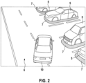
- Figure 2 shows a schematic representation of a first example of a display on the display device 4.
- detected obstacles from the surroundings of the vehicle are displayed as virtual three-dimensional objects 5 in a virtual three-dimensional space 6.
- frames 7 are displayed around the obstacles 5.
- the driver of the vehicle 1 can thus easily recognize the obstacles in the surroundings using the virtual three-dimensional objects 5.
- a representation 10 of the vehicle 1 is displayed in the virtual three-dimensional space 6.
- FIG 3 A second example is shown.
- the display is without textures.
- the scenery is the same as in Figure 2 .
- the virtual three-dimensional objects 5 and the virtual three-dimensional space 6 are not covered with textures.
- the virtual three-dimensional objects 5 and the virtual three-dimensional space 6 only have a brightness gradient that includes a representation of the outlines of the virtual three-dimensional objects 5.
- the virtual three-dimensional objects 5 are highlighted by highlights 7.
- the information content is limited to the presence and absence of obstacles.
- the driver of the vehicle 1 is therefore not overwhelmed by the multitude of different textures, but rather the driver of the vehicle 1 can concentrate on not colliding with obstacles in the environment, which means always keeping a distance between the representation 10 of the vehicle 1 and the virtual three-dimensional objects 5.
- Figure 4 shows a third example of the representation. It uses textures as in Figure 2 In contrast to Figure 2 In this example, a filter is placed over the textures. One such filter is a shade of gray. This increases the contrast of the display, while at the same time the color depth is reduced. In this way, a display is realized that, in terms of its information content, lies between the Figure 2 and the one in Figure 3 shown representation. Textures are also shown to the driver of the vehicle so that obstacles that may not have been recognized can be recognized by the driver, while at the same time the recognized obstacles can be reliably recognized by the driver through the virtual three-dimensional objects 5.
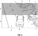
- Figure 5 a fourth example.
- the representation is divided into a first area 8 and a second area 9.
- the first area 8 corresponds to the first example, as in Figure 2 while the second area 9 corresponds to the third example, as shown in Figure 3 shown.
Landscapes
- Engineering & Computer Science (AREA)
- Multimedia (AREA)
- Signal Processing (AREA)
- Physics & Mathematics (AREA)
- General Physics & Mathematics (AREA)
- Mechanical Engineering (AREA)
- Computer Graphics (AREA)
- Theoretical Computer Science (AREA)
- Computer Hardware Design (AREA)
- General Engineering & Computer Science (AREA)
- Software Systems (AREA)
- Architecture (AREA)
- Closed-Circuit Television Systems (AREA)
- Traffic Control Systems (AREA)
- Image Processing (AREA)
- Studio Devices (AREA)
- Image Analysis (AREA)
Description
- Die vorliegende Erfindung betrifft ein Verfahren zur Darstellung von Bildern eines Kamerasystems eines Fahrzeugs. Insbesondere handelt es sich bei dem Kamerasystem um ein Rundumsichtsystem, das Bilder rund um ein Fahrzeug erfassen kann.
- Aus dem Stand der Technik sind solche Rundumsichtsysteme als Surround-View-Systems (SVS) bekannt. Beispielsweise beschreiben die folgenden Veröffentlichungen solche Systeme: "360 Wrap-Around Video Imaging Technology Ready for Integration with Fujitsu Graphics SoCs", Januar 2014; Esparza Garcia: "3D Reconstruction for Optimal Repräsentation of Surroundings in Automotive HMIs, Baseds on Fisheye Multicamera Systems", Dissertation 2015. Solche Systeme verwenden verschiedene Datentypen, um eine maximale Anzahl an Informationen anzuzeigen. Auf diese Weise wird dem Fahrer die maximale Anzahl an Informationen, die das System bereitstellen kann, angezeigt. Solche Datentypen können insbesondere aus Sensordatenfusionen, aus Informationen einer Cloud, sowie aus vielen anderen Quellen gewonnen werden. Typische Daten aus Sensordatenfusionen umfassen Informationen über belegte und freie Flächen rund um das Fahrzeug, die mittels Videosensoren, Radar-Sensoren, Lidar-Sensoren oder anderen Umfeldsensoren des Fahrzeugs ermittelt werden. Informationen aus einer Cloud können insbesondere Wetterbedingungen und verfügbare Parkplätze sein.
- Durch die Vielzahl von Informationen, die durch das SVS angezeigt werden sollen, kann der Fahrer des Fahrzeugs überfordert werden, wenn diese nicht entsprechend angezeigt werden. Dies führt dazu, dass Daten unnötigerweise erfasst werden, die dem Fahrer keinen Mehrwert liefern, da er deren Informationen nicht erkennt. Gleichzeitig wird im Stand der Technik mit erheblichem Rechenaufwand eine sehr aufwendige Anzeige erstellt, die sämtliche Informationen, die dem Surround-View-System zur Verfügung stehen, in einem Anzeigebild integriert. Dieser erhebliche Rechenaufwand ist jedoch oftmals nicht notwendig, um dem Fahrer die aktuell relevanten Informationen darzustellen.
- Die Erfindung wird durch die unabhängigen Ansprüche definiert. Das erfindungsgemäße Verfahren ermöglicht ein Anzeigen von Informationen in unterschiedlichen Darstellungen. Die Darstellungen werden anhand eines Selektionskriteriums festgelegt. Auf diese Weise ist einerseits ermöglicht, dem Fahrer nur relevante Informationen darzustellen, andererseits ist eine Rechenleistung des Gegendarstellung generierenden Systems erheblich reduziert.
- Das erfindungsgemäße Verfahren zur Darstellung von Bildern eines Kamerasystems eines Fahrzeugs ist dazu vorgesehen, dass mit besagtem Kamerasystem erfasste Hindernisse aus der Umgebung des Fahrzeugs auf einer Anzeigevorrichtung dargestellt werden. Das Darstellen erfolgt in einem virtuellen dreidimensionalen Raum. In diesem virtuellen dreidimensionalen Raum werden die erfassten Hindernisse als virtuelle dreidimensionale Objekte dargestellt. Somit erhält der Betrachter den Eindruck, dass es sich um eine räumliche Darstellung handelt, in der räumliche Objekte dargestellt sind. Dies entspricht einem virtuellen Blick auf die tatsächliche Szenerie aus einer entsprechenden virtuellen Kameraposition. Dem Fahrer des Fahrzeugs ist damit eine Übersicht über die aktuelle Szenerie bereitstellbar. Um einerseits die relevanten Informationen optimal darzustellen, andererseits um eine Rechenleistung des die Darstellung auf der Anzeigevorrichtung generierenden Systems zu reduzieren, wird anhand eines Selektionskriteriums festgelegt, ob die virtuellen dreidimensionalen Objekte und/oder der virtuelle dreidimensionale Raum mit Texturen belegt werden, die durch das Kamerasystem generiert werden, oder mit zumindest einer vordefinierten Textur belegt werden. Die vordefinierte Textur kann auch eine einzelne Farbe in verschiedenen Schattierungen sein, so dass auf der Anzeigevorrichtung keinerlei Textur dargestellt wird. Durch den Verzicht auf die tatsächlichen Texturen, d. h. auf die Texturen, die durch das Kamerasystem generiert werden, lässt sich einerseits der Informationsgehalt der Darstellung auf der Anzeigevorrichtung reduzieren, andererseits ist der Rechenaufwand zum Generieren der Darstellung reduziert. Somit wird einerseits dem Fahrer des Fahrzeugs ein Fokus auf relevante Informationen ermöglicht, andererseits wird die benötigte Rechenleistung erheblich reduziert.
- Die Unteransprüche haben bevorzugte Weiterbildungen der Erfindung zum Inhalt.
- Vorteilhafterweise wird anhand des Selektionskriteriums festgelegt, ob die zum Belegen der virtuellen dreidimensionalen Objekte und/oder des virtuellen dreidimensionalen Raums vorgesehene Texturen mittels eines vordefinierten Filters bearbeitet werden. Insbesondere kann durch den vordefinierten Filter ein Kontrast der Texturen erhöht werden. Somit besteht weiterhin die Möglichkeit, Texturen darzustellen, während gleichzeitig ein Erkennen der virtuellen dreidimensionalen Objekte auf der Anzeigevorrichtung verbessert ist.
- Insbesondere ist vorgesehen, dass der vordefinierte Filter eine Grauschattierung umfasst. Die Grauschattierung verringert die Farbtiefe der Texturen, wodurch eine Kontrastverstärkung eintritt. Gleichzeitig ist durch die Grauschattierung der Informationsgehalt der Texturen reduziert, so dass wiederum ein Erkennen der virtuellen dreidimensionalen Objekte auf der Anzeigevorrichtung für den Fahrer vereinfacht ist.
- Die vordefinierte Textur ist vorteilhafterweise ein vordefinierter Helligkeitsverlauf. Durch den vordefinierten Helligkeitsverlauf sind lediglich eine Kontur und/oder Außenflächen der virtuellen dreidimensionalen Objekte dargestellt. Dies bedeutet, dass lediglich Umrisse und/oder die Form der virtuellen dreidimensionalen Objekte auf der Anzeigevorrichtung erkennbar sind. Somit wird keinerlei Textur dargestellt, wodurch der Rechenaufwand beim Generieren der Darstellung auf der Anzeigevorrichtung erheblich verringert ist. Gleichzeitig kann der Fahrer des Fahrzeugs das Fahrzeug sicher und zuverlässig durch die Hindernisse in der Umgebung lenken, was insbesondere beim Einparken des Fahrzeugs von Vorteil ist. Insbesondere wird der Fahrer nicht durch die detailreichen Texturen von den eigentlichen Hindernissen abgelenkt.
- In einer weiteren bevorzugten Ausführungsform ist vorgesehen, dass zumindest ein Teil der virtuellen dreidimensionalen Objekte, insbesondere alle virtuellen dreidimensionalen Objekte, durch eine zumindest partielle Überlagerung auf der Anzeigevorrichtung hervorgehoben werden. Die Überlagerung umfasst vorteilhafterweise eine Umrahmung des entsprechenden virtuellen dreidimensionalen Objekts. Auf diese Weise lassen sich die Hindernisse in der Umgebung zuverlässig visualisieren. Der Fahrer des Fahrzeugs kann somit eindeutig erkennen, wo sich Hindernisse in der Umgebung befinden, und ob diese Hindernisse eine Gefahr für sein Fahrzeug darstellen. Ebenso sind weitere Überlagerungen vorteilhaft, die dem Fahrer zusätzliche Hinweise auf Merkmale in der Umgebung geben. So ist es beispielsweise ermöglicht, einen frei verfügbaren Parkplatz durch entsprechende Markierungen auf der Anzeigevorrichtung hervorzuheben.
- Das Selektionskriterium ist vorteilhafterweise eine Benutzereingabe. Somit ist durch den Benutzer frei wählbar, ob er eine vereinfachte Darstellung mit zumindest einer vordefinierten Textur oder eine komplexere Darstellung mit den Texturen des Kamerasystems benötigt. Ebenso kann der Benutzer festlegen, ob zumindest ein Teil der Texturen des Kamerasystems mit einem vordefinierten Filter bearbeitet werden soll. Somit kann der Fahrer frei wählen, welche Ansicht in einer aktuellen Situation den größtmöglichen Informationsgehalt bietet, ohne durch eine Vielzahl von aktuell unnötigen Informationen zu verwirren.
- Das Selektionskriterium umfasst ein Aktivieren eines Einparkassistenzsystems. In einer weiteren Ausführungsform ist bevorzugt vorgesehen, dass das Selektionskriterium ein erfolgreiches Erkennen eines Parkplatzes umfasst. Somit erfolgt ein Wechsel einer Darstellung automatisch. Auf diese Weise kann dem Fahrer des Fahrzeugs die derzeit objektiv beste Darstellung angeboten werden. So kann während eines aktiven Einparkassistenzsystems eine Darstellung mit lediglich vordefinierten Texturen verwendet werden, um dem Fahrer auf einfache Art und Weise zu illustrieren, welche Hindernisse das Einparkassistenzsystem erkannt hat und wie basierend auf diesen Hindernissen die Einparkstrategie erfolgt.
- Die Erfindung betrifft außerdem ein Computerprogramm, das eingerichtet ist, das Verfahren wie zuvor beschrieben, auszuführen. Das Computerprogramm ist insbesondere ein Computerprogramm, umfassend maschinenlesbare Instruktionen, die, wenn sie auf einer Rechenvorrichtung ausgeführt werden, die Rechenvorrichtung veranlassen, die Schritte des zuvor beschriebenen Verfahrens auszuführen. Bei der Rechenvorrichtung handelt es sich insbesondere um ein Steuergerät eines Fahrzeugs.
- Des Weiteren umfasst die Erfindung ein maschinenlesbares Speichermedium. Auf dem maschinenlesbaren Speichermedium ist das zuvor beschriebene Computerprogramm gespeichert. Bei dem maschinenlesbaren Speichermedium handelt es sich insbesondere um einen optischen Datenträger und/oder einen magnetischen Datenträger und/oder um einen Flash-Speicher.
- Schließlich betrifft die Erfindung ein Steuergerät zum Ausführen des Verfahrens, wie zuvor beschrieben. Ebenso ist das Steuergerät vorteilhafterweise zum Durchführen des Computerprogramms, wie zuvor beschrieben, ausgebildet.
- Nachfolgend werden Ausführungsbeispiele der Erfindung unter Bezugnahme auf die begleitende Zeichnung im Detail beschrieben. In der Zeichnung ist:
- Figur 1
- eine schematische Darstellung eines Fahrzeugs mit einem Steuergerät zum Ausführen eines Verfahrens gemäß einem Ausführungsbeispiel der Erfindung,
- Figur 2
- ein erstes Beispiel einer Darstellung, die mittels dem Verfahren gemäß dem Ausführungsbeispiel der Erfindung generiert wird,
- Figur 3
- ein zweites Beispiel einer Darstellung, die mittels dem Verfahren gemäß dem Ausführungsbeispiel der Erfindung generiert wird,
- Figur 4
- ein drittes Beispiel einer Darstellung, die mittels dem Verfahren gemäß dem Ausführungsbeispiel der Erfindung generiert wird, und
- Figur 5
- ein viertes Beispiel einer Darstellung, die mittels dem Verfahren gemäß dem Ausführungsbeispiel der Erfindung generiert wird.
- Ausführung der beanspruchten Erfindung:
Figur 1 zeigt schematisch ein Fahrzeug 1 umfassend ein Steuergerät 2 gemäß einem Ausführungsbeispiel der Erfindung. - Das Fahrzeug 1 umfasst ein Kamerasystem 3, das zum Erfassen einer Umgebung rund um das Fahrzeug 1 ausgebildet ist. Somit lässt sich die vollständige Umgebung des Fahrzeugs 1 durch das Kamerasystem 3 abtasten. Das Steuergerät 2 dient zum Erstellen einer Darstellung auf einer Anzeigevorrichtung 4, um dem Fahrer die Umgebung darzustellen. Dabei ist vorgesehen, dass das Steuergerät 2 die von dem Kamerasystem 3 erfassten Hindernisse aus der Umgebung des Fahrzeugs auf der Anzeigevorrichtung 4 in einem virtuellen dreidimensionalen Raum 6 als virtuelle dreidimensionale Objekte 5 darstellt. Dies ist in den
Figuren 2 - 5 gezeigt. Die Wahl der Darstellung, die auf der Anzeigevorrichtung 4 dargestellt werden soll, wird anhand eines Selektionskriteriums getroffen. - Das Selektionskriterium ist vorteilhafterweise eine Benutzereingabe. Somit kann der Benutzer wählen, welche verschiedenen Darstellungen er betrachten möchte. Alternativ kann das Selektionskriterium automatisch festgelegt werden, indem die Darstellung, basierend auf einem erfolgreichen Erkennen eines Parkplatzes und/oder basierend auf einem Aktivieren eines Einparkassistenzsystems, gewählt wird. Ziel ist, dem Fahrer des Fahrzeugs stets ein optimales Bild der Umgebung anzuzeigen, das relevante Informationen umfasst, ohne den Fahrer mit einer großen Vielzahl an Informationen zu überfordern. Gleichzeitig ist durch die selektive Wahl der Darstellung ein Rechenaufwand innerhalb des Steuergeräts 2 erheblich reduziert, da auch Darstellungen mit reduziertem Informationsgehalt auf der Anzeigevorrichtung angezeigt werden und nicht fortwährend Darstellungen mit maximalem Informationsgehalt generiert werden müssen.
-
Figur 2 zeigt schematisch ein erstes Beispiel einer Darstellung auf der Anzeigevorrichtung 4. Dabei werden erfasste Hindernisse aus der Umgebung des Fahrzeugs als virtuelle dreidimensionale Objekte 5 in einem virtuellen dreidimensionalen Raum 6 dargestellt. Zur besseren Unterscheidbarkeit ist außerdem vorgesehen, dass Umrahmungen 7 rund um die Hindernisse 5 angezeigt werden. Somit kann der Fahrer des Fahrzeugs 1 die Hindernisse in der Umgebung leicht anhand der virtuellen dreidimensionalen Objekte 5 erkennen. Zur besseren Übersicht ist außerdem bevorzugt vorgesehen, dass eine Repräsentation 10 des Fahrzeugs 1 in dem virtuellen dreidimensionalen Raum 6 angezeigt wird. - In dem in
Figur 2 gezeigten Beispiel ist vorgesehen, dass sämtliche virtuelle dreidimensionale Objekte 5 und der virtuelle dreidimensionale Raum mit Texturen belegt sind, die mittels des Kamerasystems 3 erfasst wurden. Dies bedeutet, dass eine fotorealistische Darstellung erzeugt wird. Dem Fahrer des Fahrzeugs 1 ist somit eine Vielzahl von unterschiedlichen Informationen in der Darstellung bereitgestellt. Sollten einzelne Hindernisse nicht erkannt werden, und somit auch nicht als virtuelle dreidimensionale Objekte 5 angezeigt werden, so besteht für den Fahrer weiterhin die Möglichkeit, diese Hindernisse anhand der Texturen zu erkennen. Allerdings besteht die Gefahr, dass der Fahrer des Fahrzeugs durch eine Vielzahl von Informationen überfordert ist. Somit kann der Fahrer des Fahrzeugs 1 eventuell wichtige Informationen übersehen, das bedeutet, es besteht die Gefahr, dass das Fahrzeug 1 mit einem Hindernis kollidiert, da der Fahrer die Annäherung der Repräsentation 10 des Fahrzeugs 1 an ein virtuelles dreidimensionales Objekt 5 übersehen hat. - In
Figur 3 ist ein zweites Beispiel dargestellt. In diesem Beispiel erfolgt eine Anzeige ohne Texturen. Die Szenerie ist die gleiche wie inFigur 2 . Im Unterschied zuFigur 2 werden die virtuellen dreidimensionalen Objekte 5 und der virtuelle dreidimensionale Raum 6 nicht mit Texturen belegt. Dies bedeutet, dass die virtuellen dreidimensionalen Objekte 5 und der virtuelle dreidimensionale Raum 6 lediglich einen Helligkeitsverlauf aufweisen, der eine Darstellung der Umrisse der virtuellen dreidimensionalen Objekte 5 umfasst. Bevorzugt ist wiederum vorgesehen, dass durch Hervorhebungen 7 die virtuellen dreidimensionalen Objekte 5 hervorgehoben werden. - In der in
Figur 3 gezeigten Darstellung ist ein Informationsgehalt lediglich auf das Vorhandensein und Nicht-Vorhandensein von Hindernissen beschränkt. Der Fahrer des Fahrzeugs 1 wird somit nicht durch die Vielzahl von unterschiedlichen Texturen überfordert, vielmehr kann sich der Fahrer des Fahrzeugs 1 darauf konzentrieren, nicht mit Hindernissen der Umgebung zu kollidieren, das bedeutet, stets einen Abstand zwischen der Repräsentation 10 des Fahrzeugs 1 und den virtuellen dreidimensionalen Objekten 5 zu halten. -
Figur 4 zeigt schließlich ein drittes Beispiel der Darstellung. Dabei erfolgt eine Verwendung von Texturen wie inFigur 2 dargestellt. Im Unterschied zuFigur 2 wird in diesem Beispiel ein Filter über die Texturen gelegt. Ein solcher Filter ist insbesondere eine Grauschattierung. Somit ist ein Kontrast der Anzeige erhöht, während gleichzeitig eine Farbtiefe verringert ist. Auf diese Weise ist eine Darstellung realisiert, die hinsichtlich ihres Informationsgehalts zwischen der inFigur 2 und der inFigur 3 gezeigten Darstellung rangiert. Dem Fahrer des Fahrzeugs werden weiterhin Texturen dargestellt, so dass eventuell nicht erkannte Hindernisse durch den Fahrer erkannt werden können, gleichzeitig sind die erkannten Hindernisse durch die virtuellen dreidimensionalen Objekte 5 zuverlässig durch den Fahrer erkennbar. - Schließlich zeigt
Figur 5 ein viertes Beispiel. In diesem Beispiel ist die Darstellung in einen ersten Bereich 8 und in einen zweiten Bereich 9 aufgeteilt. Dabei entspricht der erste Bereich 8 dem ersten Beispiel, wie inFigur 2 gezeigt, während der zweite Bereich 9 dem dritten Beispiel, wie inFigur 3 gezeigt, entspricht. Somit erfolgt ein Übergang von Texturen, wie durch das Kamerasystem 3 generiert, zu solchen Texturen, die mit einem vordefinierten Filter bearbeitet wurden. Somit lassen sich die Vorteile des hohen Detaillierungsgrads für einen Nahbereich mit den Vorteilen eines erhöhten Kontrasts im Fernbereich kombinieren.
Claims (9)
- Verfahren zur Darstellung von Bildern eines Kamerasystems (3) eines Fahrzeugs (1),• wobei mit dem Kamerasystem (3) erfasste Hindernisse aus der Umgebung des Fahrzeugs (1) auf einer Anzeigevorrichtung (4) in einem virtuellen dreidimensionalen Raum (6) als virtuelle dreidimensionale Objekte (5) dargestellt werden, und• wobei anhand eines Selektionskriteriums festgelegt wird, ob die virtuellen dreidimensionalen Objekte (5) und/oder der virtuelle dreidimensionale Raum (6)∘ mit Texturen belegt werden, die durch das Kamerasystem (3) generiert werden, oder∘ mit zumindest einer vordefinierten Textur belegt werden,wobei das Selektionskriterium ein Aktivieren eines Einparkassistenzsystems umfasst; wobeiein Wechsel der Darstellung automatisch erfolgt; wobeiwährend eines aktiven Einparkassistenzsystems eine Darstellung mit lediglich vordefinierten Texturen verwendet wird.
- Verfahren nach Anspruch 1, dadurch gekennzeichnet, dass anhand des Selektionskriteriums festgelegt wird, ob die zum Belegen der virtuellen dreidimensionalen Objekte (5) und/oder des virtuellen dreidimensionalen Raums (6) vorgesehenen Texturen mittels eines vordefinierten Filters bearbeitet werden.
- Verfahren nach Anspruch 2, dadurch gekennzeichnet, dass der vordefinierte Filter eine Grauschattierung umfasst.
- Verfahren nach einem der vorhergehenden Ansprüche, dadurch gekennzeichnet, dass die vordefinierte Textur ein vordefinierter Helligkeitsverlauf ist, um lediglich eine Kontur und/oder Außenflächen der virtuellen dreidimensionalen Objekte (5) darzustellen.
- Verfahren nach einem der vorhergehenden Ansprüche, dadurch gekennzeichnet, dass zumindest ein Teil der virtuellen dreidimensionalen Objekte (5), insbesondere alle virtuelle dreidimensionale Objekte (5), durch eine zumindest partielle Überlagerung (7), insbesondere durch eine Umrahmung, auf der Anzeigevorrichtung (4) hervorgehoben werden.
- Verfahren nach einem der vorhergehenden Ansprüche, dadurch gekennzeichnet, dass das Selektionskriterium eine Benutzereingabe ist.
- Computerprogramm, umfassend Befehle, die bei der Ausführung des Programms durch einen Computer diesen veranlassen, die Schritte des Verfahrens nach einem der vorhergehenden Ansprüche auszuführen.
- Maschinenlesbares Speichermedium, auf dem das Computerprogramm nach Anspruch 7 gespeichert ist.
- Steuergerät (2) eingerichtet zum Ausführen des Verfahrens nach einem der Ansprüche 1 bis 6.
Applications Claiming Priority (2)
| Application Number | Priority Date | Filing Date | Title |
|---|---|---|---|
| DE102017218090.0A DE102017218090A1 (de) | 2017-10-11 | 2017-10-11 | Verfahren zur Darstellung von Bildern eines Kamerasystems eines Fahrzeugs |
| PCT/EP2018/074273 WO2019072466A1 (de) | 2017-10-11 | 2018-09-10 | Verfahren zur darstellung von bildern eines kamerasystems eines fahrzeugs |
Publications (2)
| Publication Number | Publication Date |
|---|---|
| EP3695387A1 EP3695387A1 (de) | 2020-08-19 |
| EP3695387B1 true EP3695387B1 (de) | 2024-11-06 |
Family
ID=63637872
Family Applications (1)
| Application Number | Title | Priority Date | Filing Date |
|---|---|---|---|
| EP18772764.9A Active EP3695387B1 (de) | 2017-10-11 | 2018-09-10 | Verfahren zur darstellung von bildern eines kamerasystems eines fahrzeugs |
Country Status (6)
| Country | Link |
|---|---|
| US (1) | US20200267364A1 (de) |
| EP (1) | EP3695387B1 (de) |
| JP (1) | JP7105879B2 (de) |
| CN (1) | CN111213185B (de) |
| DE (1) | DE102017218090A1 (de) |
| WO (1) | WO2019072466A1 (de) |
Families Citing this family (2)
| Publication number | Priority date | Publication date | Assignee | Title |
|---|---|---|---|---|
| DE102020215696B4 (de) | 2020-12-11 | 2024-03-14 | Robert Bosch Gesellschaft mit beschränkter Haftung | Verfahren zur Darstellung einer Umgebung eines Fahrzeugs, Computerprogrammprodukt, Speichermedium, Steuergerät und Fahrzeug |
| CN117644858A (zh) * | 2024-01-30 | 2024-03-05 | 安徽中科星驰自动驾驶技术有限公司 | 一种基于障碍物判断车速的自动驾驶泊车测速系统 |
Family Cites Families (9)
| Publication number | Priority date | Publication date | Assignee | Title |
|---|---|---|---|---|
| JP4374850B2 (ja) | 2002-12-24 | 2009-12-02 | アイシン精機株式会社 | 移動体周辺監視装置 |
| JP4092479B2 (ja) | 2003-01-07 | 2008-05-28 | 日産自動車株式会社 | 車両用運転支援装置 |
| JP2004320567A (ja) | 2003-04-17 | 2004-11-11 | Sumitomo Electric Ind Ltd | 撮像装置、画像表示システム、画像表示方法、画像処理システム及び画像処理方法 |
| JP2005268847A (ja) * | 2004-03-16 | 2005-09-29 | Olympus Corp | 画像生成装置、画像生成方法、および画像生成プログラム |
| JP2008126794A (ja) | 2006-11-20 | 2008-06-05 | Suzuki Motor Corp | 車両用外部情報表示装置 |
| JP2011205513A (ja) | 2010-03-26 | 2011-10-13 | Aisin Seiki Co Ltd | 車両周辺監視装置 |
| CN101976460B (zh) * | 2010-10-18 | 2012-02-22 | 无锡维森智能传感技术有限公司 | 车载多目摄像机环视系统的虚拟视点图像生成方法 |
| JP6205923B2 (ja) | 2013-07-11 | 2017-10-04 | 株式会社デンソー | 走行支援装置 |
| JP5597781B1 (ja) | 2014-03-26 | 2014-10-01 | パナソニック株式会社 | 滞留状況分析装置、滞留状況分析システムおよび滞留状況分析方法 |
-
2017
- 2017-10-11 DE DE102017218090.0A patent/DE102017218090A1/de not_active Withdrawn
-
2018
- 2018-09-10 JP JP2020520226A patent/JP7105879B2/ja active Active
- 2018-09-10 US US16/651,684 patent/US20200267364A1/en not_active Abandoned
- 2018-09-10 EP EP18772764.9A patent/EP3695387B1/de active Active
- 2018-09-10 CN CN201880066136.9A patent/CN111213185B/zh active Active
- 2018-09-10 WO PCT/EP2018/074273 patent/WO2019072466A1/de not_active Ceased
Also Published As
| Publication number | Publication date |
|---|---|
| WO2019072466A1 (de) | 2019-04-18 |
| EP3695387A1 (de) | 2020-08-19 |
| CN111213185A (zh) | 2020-05-29 |
| JP2020537422A (ja) | 2020-12-17 |
| JP7105879B2 (ja) | 2022-07-25 |
| CN111213185B (zh) | 2024-11-15 |
| US20200267364A1 (en) | 2020-08-20 |
| DE102017218090A1 (de) | 2019-04-11 |
Similar Documents
| Publication | Publication Date | Title |
|---|---|---|
| EP3695395B1 (de) | Verfahren zum darstellen einer umgebung eines fahrzeugs | |
| EP3281178B1 (de) | Verfahren zur darstellung einer fahrzeugumgebung eines fahrzeuges | |
| DE102006003538B3 (de) | Verfahren zum Zusammenfügen mehrerer Bildaufnahmen zu einem Gesamtbild in der Vogelperspektive | |
| DE102016114288A1 (de) | Einparkhilfevorrichtung und verfahren zum steuern derselben | |
| DE102019120636B4 (de) | Periphere anzeigevorrichtung für ein fahrzeug | |
| DE102009029439A1 (de) | Verfahren und Vorrichtung zur Darstellung von Hindernissen in einem Einparkhilfesystem von Kraftfahrzeugen | |
| DE102014208664A1 (de) | Verfahren und vorrichtung zum verzerrungsfreien anzeigen einer fahrzeugumgebung eines fahrzeuges | |
| DE102021130548A1 (de) | Auf Auffälligkeiten gestützte Präsentation von Objekten in einem Bild | |
| EP2559236A1 (de) | Verfahren zum anzeigen eines bildes auf einer anzeigeeinrichtung in einem fahrzeug, fahrerassistenzsystem und fahrzeug | |
| EP3053133A1 (de) | Verfahren und vorrichtung zur anzeige der umgebung eines fahrzeugs und fahrerassistenzsystem | |
| DE102009035422B4 (de) | Verfahren zur geometrischen Bildtransformation | |
| EP3308361B1 (de) | Verfahren zur erzeugung eines virtuellen bildes einer fahrzeugumgebung | |
| DE102012212577A1 (de) | System und verfahren für ein video mit verbesserter tiefenwahrnehmung | |
| DE102015202863A1 (de) | Verfahren und Vorrichtung zum verzerrungsfreien Anzeigen einer Fahrzeugumgebung eines Fahrzeuges | |
| DE102013220477A1 (de) | Verfahren zur Korrektur einer bildlichen Darstellung einer Fahrzeugumgebung | |
| EP3695387B1 (de) | Verfahren zur darstellung von bildern eines kamerasystems eines fahrzeugs | |
| EP3571091B1 (de) | Verfahren und vorrichtung zum darstellen einer umgebung eines fahrzeuges | |
| DE102013016241A1 (de) | Verfahren und Vorrichtung zur augmentierten Darstellung | |
| EP4208372A1 (de) | Verfahren zum anzeigen einer umgebung eines fahrzeuges auf einer anzeigeeinrichtung, verarbeitungseinheit und fahrzeug | |
| DE102018130229B4 (de) | Verfahren und Vorrichtung zur Objektextraktion aus eine dreidimensionale Szene darstellenden Szenenbilddaten | |
| DE102020215696A1 (de) | Verfahren zur Darstellung einer Umgebung eines Fahrzeugs, Computerprogrammprodukt, Speichermedium, Steuergerät und Fahrzeug | |
| DE112018005744T5 (de) | Bedienerassistenz-sichtsystem | |
| DE102015201642A1 (de) | Vorrichtung und Verfahren zur Darstellung einer Umgebung eines Fahrzeuges | |
| EP2804785B1 (de) | Anzeigesystem für ein fahrzeug | |
| EP2312525A2 (de) | Verfahren und Kamerasystem zur Erzeugung von Bildern zur Übermittlung an eine externe Steuereinheit |
Legal Events
| Date | Code | Title | Description |
|---|---|---|---|
| STAA | Information on the status of an ep patent application or granted ep patent |
Free format text: STATUS: UNKNOWN |
|
| STAA | Information on the status of an ep patent application or granted ep patent |
Free format text: STATUS: THE INTERNATIONAL PUBLICATION HAS BEEN MADE |
|
| PUAI | Public reference made under article 153(3) epc to a published international application that has entered the european phase |
Free format text: ORIGINAL CODE: 0009012 |
|
| STAA | Information on the status of an ep patent application or granted ep patent |
Free format text: STATUS: REQUEST FOR EXAMINATION WAS MADE |
|
| 17P | Request for examination filed |
Effective date: 20200511 |
|
| AK | Designated contracting states |
Kind code of ref document: A1 Designated state(s): AL AT BE BG CH CY CZ DE DK EE ES FI FR GB GR HR HU IE IS IT LI LT LU LV MC MK MT NL NO PL PT RO RS SE SI SK SM TR |
|
| AX | Request for extension of the european patent |
Extension state: BA ME |
|
| DAV | Request for validation of the european patent (deleted) | ||
| DAX | Request for extension of the european patent (deleted) | ||
| STAA | Information on the status of an ep patent application or granted ep patent |
Free format text: STATUS: EXAMINATION IS IN PROGRESS |
|
| 17Q | First examination report despatched |
Effective date: 20220301 |
|
| GRAP | Despatch of communication of intention to grant a patent |
Free format text: ORIGINAL CODE: EPIDOSNIGR1 |
|
| STAA | Information on the status of an ep patent application or granted ep patent |
Free format text: STATUS: GRANT OF PATENT IS INTENDED |
|
| INTG | Intention to grant announced |
Effective date: 20240702 |
|
| GRAS | Grant fee paid |
Free format text: ORIGINAL CODE: EPIDOSNIGR3 |
|
| GRAA | (expected) grant |
Free format text: ORIGINAL CODE: 0009210 |
|
| STAA | Information on the status of an ep patent application or granted ep patent |
Free format text: STATUS: THE PATENT HAS BEEN GRANTED |
|
| AK | Designated contracting states |
Kind code of ref document: B1 Designated state(s): AL AT BE BG CH CY CZ DE DK EE ES FI FR GB GR HR HU IE IS IT LI LT LU LV MC MK MT NL NO PL PT RO RS SE SI SK SM TR |
|
| REG | Reference to a national code |
Ref country code: GB Ref legal event code: FG4D Free format text: NOT ENGLISH |
|
| REG | Reference to a national code |
Ref country code: CH Ref legal event code: EP |
|
| REG | Reference to a national code |
Ref country code: DE Ref legal event code: R096 Ref document number: 502018015305 Country of ref document: DE |
|
| REG | Reference to a national code |
Ref country code: IE Ref legal event code: FG4D Free format text: LANGUAGE OF EP DOCUMENT: GERMAN |
|
| REG | Reference to a national code |
Ref country code: LT Ref legal event code: MG9D |
|
| REG | Reference to a national code |
Ref country code: NL Ref legal event code: MP Effective date: 20241106 |
|
| PG25 | Lapsed in a contracting state [announced via postgrant information from national office to epo] |
Ref country code: PT Free format text: LAPSE BECAUSE OF FAILURE TO SUBMIT A TRANSLATION OF THE DESCRIPTION OR TO PAY THE FEE WITHIN THE PRESCRIBED TIME-LIMIT Effective date: 20250306 Ref country code: HR Free format text: LAPSE BECAUSE OF FAILURE TO SUBMIT A TRANSLATION OF THE DESCRIPTION OR TO PAY THE FEE WITHIN THE PRESCRIBED TIME-LIMIT Effective date: 20241106 Ref country code: IS Free format text: LAPSE BECAUSE OF FAILURE TO SUBMIT A TRANSLATION OF THE DESCRIPTION OR TO PAY THE FEE WITHIN THE PRESCRIBED TIME-LIMIT Effective date: 20250306 |
|
| PG25 | Lapsed in a contracting state [announced via postgrant information from national office to epo] |
Ref country code: FI Free format text: LAPSE BECAUSE OF FAILURE TO SUBMIT A TRANSLATION OF THE DESCRIPTION OR TO PAY THE FEE WITHIN THE PRESCRIBED TIME-LIMIT Effective date: 20241106 Ref country code: NL Free format text: LAPSE BECAUSE OF FAILURE TO SUBMIT A TRANSLATION OF THE DESCRIPTION OR TO PAY THE FEE WITHIN THE PRESCRIBED TIME-LIMIT Effective date: 20241106 |
|
| PG25 | Lapsed in a contracting state [announced via postgrant information from national office to epo] |
Ref country code: BG Free format text: LAPSE BECAUSE OF FAILURE TO SUBMIT A TRANSLATION OF THE DESCRIPTION OR TO PAY THE FEE WITHIN THE PRESCRIBED TIME-LIMIT Effective date: 20241106 |
|
| PG25 | Lapsed in a contracting state [announced via postgrant information from national office to epo] |
Ref country code: ES Free format text: LAPSE BECAUSE OF FAILURE TO SUBMIT A TRANSLATION OF THE DESCRIPTION OR TO PAY THE FEE WITHIN THE PRESCRIBED TIME-LIMIT Effective date: 20241106 |
|
| PG25 | Lapsed in a contracting state [announced via postgrant information from national office to epo] |
Ref country code: NO Free format text: LAPSE BECAUSE OF FAILURE TO SUBMIT A TRANSLATION OF THE DESCRIPTION OR TO PAY THE FEE WITHIN THE PRESCRIBED TIME-LIMIT Effective date: 20250206 |
|
| PG25 | Lapsed in a contracting state [announced via postgrant information from national office to epo] |
Ref country code: LV Free format text: LAPSE BECAUSE OF FAILURE TO SUBMIT A TRANSLATION OF THE DESCRIPTION OR TO PAY THE FEE WITHIN THE PRESCRIBED TIME-LIMIT Effective date: 20241106 Ref country code: GR Free format text: LAPSE BECAUSE OF FAILURE TO SUBMIT A TRANSLATION OF THE DESCRIPTION OR TO PAY THE FEE WITHIN THE PRESCRIBED TIME-LIMIT Effective date: 20250207 |
|
| PG25 | Lapsed in a contracting state [announced via postgrant information from national office to epo] |
Ref country code: PL Free format text: LAPSE BECAUSE OF FAILURE TO SUBMIT A TRANSLATION OF THE DESCRIPTION OR TO PAY THE FEE WITHIN THE PRESCRIBED TIME-LIMIT Effective date: 20241106 |
|
| PG25 | Lapsed in a contracting state [announced via postgrant information from national office to epo] |
Ref country code: RS Free format text: LAPSE BECAUSE OF FAILURE TO SUBMIT A TRANSLATION OF THE DESCRIPTION OR TO PAY THE FEE WITHIN THE PRESCRIBED TIME-LIMIT Effective date: 20250206 |
|
| PG25 | Lapsed in a contracting state [announced via postgrant information from national office to epo] |
Ref country code: SM Free format text: LAPSE BECAUSE OF FAILURE TO SUBMIT A TRANSLATION OF THE DESCRIPTION OR TO PAY THE FEE WITHIN THE PRESCRIBED TIME-LIMIT Effective date: 20241106 |
|
| PG25 | Lapsed in a contracting state [announced via postgrant information from national office to epo] |
Ref country code: DK Free format text: LAPSE BECAUSE OF FAILURE TO SUBMIT A TRANSLATION OF THE DESCRIPTION OR TO PAY THE FEE WITHIN THE PRESCRIBED TIME-LIMIT Effective date: 20241106 |
|
| PG25 | Lapsed in a contracting state [announced via postgrant information from national office to epo] |
Ref country code: EE Free format text: LAPSE BECAUSE OF FAILURE TO SUBMIT A TRANSLATION OF THE DESCRIPTION OR TO PAY THE FEE WITHIN THE PRESCRIBED TIME-LIMIT Effective date: 20241106 |
|
| PG25 | Lapsed in a contracting state [announced via postgrant information from national office to epo] |
Ref country code: RO Free format text: LAPSE BECAUSE OF FAILURE TO SUBMIT A TRANSLATION OF THE DESCRIPTION OR TO PAY THE FEE WITHIN THE PRESCRIBED TIME-LIMIT Effective date: 20241106 |
|
| PG25 | Lapsed in a contracting state [announced via postgrant information from national office to epo] |
Ref country code: SK Free format text: LAPSE BECAUSE OF FAILURE TO SUBMIT A TRANSLATION OF THE DESCRIPTION OR TO PAY THE FEE WITHIN THE PRESCRIBED TIME-LIMIT Effective date: 20241106 |
|
| PG25 | Lapsed in a contracting state [announced via postgrant information from national office to epo] |
Ref country code: CZ Free format text: LAPSE BECAUSE OF FAILURE TO SUBMIT A TRANSLATION OF THE DESCRIPTION OR TO PAY THE FEE WITHIN THE PRESCRIBED TIME-LIMIT Effective date: 20241106 |
|
| PG25 | Lapsed in a contracting state [announced via postgrant information from national office to epo] |
Ref country code: IT Free format text: LAPSE BECAUSE OF FAILURE TO SUBMIT A TRANSLATION OF THE DESCRIPTION OR TO PAY THE FEE WITHIN THE PRESCRIBED TIME-LIMIT Effective date: 20241106 |
|
| REG | Reference to a national code |
Ref country code: DE Ref legal event code: R097 Ref document number: 502018015305 Country of ref document: DE |
|
| PG25 | Lapsed in a contracting state [announced via postgrant information from national office to epo] |
Ref country code: SE Free format text: LAPSE BECAUSE OF FAILURE TO SUBMIT A TRANSLATION OF THE DESCRIPTION OR TO PAY THE FEE WITHIN THE PRESCRIBED TIME-LIMIT Effective date: 20241106 |
|
| PLBE | No opposition filed within time limit |
Free format text: ORIGINAL CODE: 0009261 |
|
| STAA | Information on the status of an ep patent application or granted ep patent |
Free format text: STATUS: NO OPPOSITION FILED WITHIN TIME LIMIT |
|
| 26N | No opposition filed |
Effective date: 20250807 |
|
| PGFP | Annual fee paid to national office [announced via postgrant information from national office to epo] |
Ref country code: DE Payment date: 20251121 Year of fee payment: 8 |